
Snake Robots for Surgical Applications: A Review


Mechanical Engineering Group, School of Engineering, University of Kent, Canterbury CT2 7NT, UK
*
Authors to whom correspondence should be addressed.
Robotics 2022, 11(3), 57; https://doi.org/10.3390/robotics11030057
Submission received: 4 March 2022
/
Revised: 25 April 2022
/
Accepted: 28 April 2022
/
Published: 5 May 2022
(This article belongs to the Special Issue Advanced Technologies for Autonomous Surgical Robotics)
Abstract
:Although substantial advancements have been achieved in robot-assisted surgery, the blueprint to existing snake robotics predominantly focuses on the preliminary structural design, control, and human–robot interfaces, with features which have not been particularly explored in the literature. This paper aims to conduct a review of planning and operation concepts of hyper-redundant serpentine robots for surgical use, as well as any future challenges and solutions for better manipulation. Current researchers in the field of the manufacture and navigation of snake robots have faced issues, such as a low dexterity of the end-effectors around delicate organs, state estimation and the lack of depth perception on two-dimensional screens. A wide range of robots have been analysed, such as the i2Snake robot, inspiring the use of force and position feedback, visual servoing and augmented reality (AR). We present the types of actuation methods, robot kinematics, dynamics, sensing, and prospects of AR integration in snake robots, whilst addressing their shortcomings to facilitate the surgeon’s task. For a smoother gait control, validation and optimization algorithms such as deep learning databases are examined to mitigate redundancy in module linkage backlash and accidental self-collision. In essence, we aim to provide an outlook on robot configurations during motion by enhancing their material compositions within anatomical biocompatibility standards.
1. Introduction
In the wake of the surging coronavirus pandemic, robotic surgery has had an integral role in shielding frontline workers, in a quest to lower hospitalizations and reduce the burden on healthcare systems. Medical robots and their inherent ability to perform surgeries at an affordable and accessible rate have encouraged their widespread deployment in hospitals and clinics on a national and global level. According to CMR Surgical (https://cmrsurgical.com/) (accessed on 8 November 2021), one of the world’s leading healthcare giants, there were approximately 70 robots in circulation within the UK’s clinical sector, and a total of approximately one million interventions performed by roughly 4500 robotic platforms worldwide [1]. Furthermore, the exponential increase in urgency for robotic surgery has seen an 178% increase in operations across the globe, predominantly in the US, over a wide range of specialties in 2015 [2].
In more recent times, localized drug delivery, self-deployment and remote diagnostics monitoring by robots have been proposed and developed by researchers for deployment in hospitals, especially in China and Japan, when the infections started soaring in late February 2019 [3,4,5,6,7,8]. An increased dexterity and manoeuvrability are at the core centre of the motion planning and control of these medical robots, including handheld robots and master–slave remote systems. The rate at which the train of development is moving accentuates the rising interest for articulated robots which can travel through anatomical orifices, as a product of minimally invasive surgery. Deeper incisions during intervention have since become redundant, prioritizing comfort and the accelerated risk-free recovery for end-users.
Over time, extensive literature has shed light on the importance of greater degrees of freedom (DOF), higher system reliability, increased fault tolerance and complex trajectory mapping to ensure ease of locomotion. Existing endoscopic systems provide an amalgamation of passive malleability and remote control via actuation gears. The surgical instruments, which can either be rigid or steerable, are remotely accessed by medical staff, in parallel with a head-mounted display such as a monitor annexed to a camera. These robots require tips of an estimated diameter of 3–4 mm for a greater range of motion during insertion into natural orifices, operational channels and biopsy ports [9]. Common actuation infrastructures include multiple micromotors and are embedded with interconnected proximal tendons to allow for increased range and dexterity when manoeuvring in complex biological environments.
1.1. Medical Background and Rationale
The widespread demand for snake robots in surgical settings has generated the momentum for this review paper, with a central focus on the challenges encountered in their deployment as well as unconventional solutions for the control, manufacture, sensing, and kinematics of the robotic systems. This paper aims to review different types of continuum robots available commercially for surgery and in the academic literature, as well as their current specifications in terms of overall design, locomotion and AR integration. Owing to the recent acclamation of MIS procedures, the prevalent cynicism over the constrained work environment, reduced haptic feedback and depth perception has been put to rest due to the implementation of intelligent control algorithms.
In line with the medicolegal regulations of countries, robot-assisted MIS has gained popularity in hospitals and medical centres, with a core interest in snake-like robots for targeted penetration. Apart from their roles in moving on virtual terrains to being appreciable swimmers, from a surgeon’s perspective, these serpentine structures are morphable and thoroughly articulated for deployment at multiple access sites during laparoscopy-based surgeries. Conventional MIS has the upper hand over most VR-assisted surgeries, with only 2.5% of the total number of cases of posthiatal repair and Toulet’s fundoplication recurring in 40 consecutive patients after an 11-month check-up session, as shown in [10]. Recent studies by a team of researchers at the Massachusetts Institute of Technology (MIT) have proved successful in the treatment of aneurysms and strokes in the cerebral regions, controlled by an electromagnet-powered, surface-mounted slithering catheter, paving the way for research in navigation around delicate and riskier regions such as the brain and the heart [11].
The types of surgery considered in this research include:
- Neurosurgery;
- Ophthalmic surgery;
- Otolaryngology;
- Cardiothoracic surgery;
- Urological surgery;
- Gynaecology;
- Pancreatectomy;
- Prostate surgery.
The main target areas in the human body for snake-like robots are described as follows:
- Tonsils and adenoids: Transoral robotic surgery is performed via the oral cavity, using a Crowe–Davis mouth gag for increased surgical exposure. The swelling of the tonsils at the rear end of the throat, which protect the body from infection, requires intervention to expedite swallowing movements. Sometimes, such inflammation in the throat can cause obstructive sleep apnoea and, in worst cases, high blood pressure and depression [12].
- Thyroids: Robotic thyroidectomy omits any dissection through the neck which may be highly risky, and instead utilizes a transaxillary approach with an incision of 5–7 cm via the underarm. There is scope for a flexible snake robot to be steered around the bony protrusions under the neck, around the collar bone and at the axilla, despite the restricted working area [13].
- Neck: Cancerous lesions can be extracted inside or on the neck using robotic techniques such as electrocautery. When the metastatic neck epithelium becomes cancerous, the affected cells spread to the lymph nodes in the neck. Robots are highly involved in biopsies, the microscope inspection and removal of neck tissue using endoscopic procedures through the nose, throat, rear of the tongue, stomach area, trachea and windpipe. Other treatments available for premature stages of throat cancer include cordectomy, laryngoscopy, vocal cord surgery, uvulectomy and free autologous tissue transfer [14,15].
- Trachea: The widening of a narrowed windpipe below the larynx requires urgent treatment due to breathlessness and fatigue experienced by the patient, usually reflected in children. Robotic laryngotracheal reconstruction is carried out by flexible endoscopic robots, widening the lumen through the use of a cartilage graft for anastomosis and enabling the cross-field respiration of the airways [16].
- Hiatic hernia: The excrescence of the upper abdomen, into the mediastinum through the hiatus of the diaphragm. Incompetency of the lower sphincter is caused by the loosening of the pharyngoesophageal membrane and expansion of the diaphragmatic hiatus. A peroral endoscopic myotomy and Nissen fundoplication can be performed using a flexible snake robot and are used to treat gastroesophageal reflux disease (GERD), increasing digestive mobility [17].
- Gastrointestinal tumours: The interstitial cells of the smooth muscle in the digestive tract may develop cancerous attributes. A laparoscopic pancreaticoduodenectomy, which is the removal of duodenal intestinal stromal tumours, involves excisions, suturing and anastomosing the inner walls of the stomach using a multifunctional robotic tip due to its malleability in restricted areas. The emerging treatment options for such robots include targeted drug delivery and the use of surgical patches for ulcers and tumours [18].
For further reading on the types of robotic surgery performed in clinic, readers can refer to the Handbook of Medical Applications: Robotic-Assisted Minimally Invasive Surgery [12].
1.2. Outline
The organization of this paper is as follows:
Section 2 presents the data collected during the literature review, including the commercialized and experimental snake robots deployed in hospitals and clinics. Section 3 outlines the types of continuum robots and the principal driving mechanisms in their design.
Section 4 elaborates on the materials and manufacturing techniques for snake robots used in industry, with focus on innovative printing processes and devices. Section 5 explains the methodology in terms of dynamics and control, as well as the gait equations utilized to control the desired angles and angular velocities.
Section 6 illustrates the algorithms in the planning and navigation of the snake robot and the mathematical equations involved in robot motion, such as triangulation. Section 7 provides information about sensors and instrumentation, which are employed in the surgical control system for obstacle avoidance and desired robot locomotion.
Section 8 emphasizes the validation and verification infrastructure in place for surgical robotic systems. Finally, Section 9 presents the research gaps in the performance, design and control of snake robots by rationalizing the criteria by which the surgical devices are classified in the literature review, in separate subsections for each idea.
2. Literature Review
The following section describes the numerous master–slave platforms manufactured and patented by researchers in existing studies, with a primary focus on targeting natural orifices through multiport access sites.
2.1. Commercial Snake Robot Systems
The history of surgical endoscopes dates back to the 1990s, when the first robotic system AESOP was introduced by Computer Motion, Inc. (Goleta, CA, USA), and, eventually, the evolved version ZEUS reflected the former’s multifunctional features, including dictation and tactile feedback [4]. In line with the recent state-of-the-art technological advances, the chronological timeline of robotic systems portrays progressive control mechanisms with varying multichannelling methods for biopsies [19], reconstruction [20] and ablation [21]. Moreover, joystick interfaces are widely used to steer robotic controllers, for tip angulation, aeration, water suction, rinsing, overhead docking, shaft rotation as well as contraction, as described by Ruiter et al. [22]. The single-use colonoscope Aer-O-Scope operates based on propulsion for colon cannulation and examination. The device insufflates CO2 by way of balloons for the generation of a pneumatic actuation force [23]. The operation of the LESS system is based on the interchangeable phases of its actuating port material, usually piezoelectric. Its platform consists of two robotic instruments, which are manually controlled to perform an intervention [24]. The MASTER system provides the surgeon with extra coordination during tissue manipulation due to its five DOF instrumentation platform, which has a collective outer diameter of 25 mm [25]. Another robotic system in the spotlight is called the IREP, which, when coupled with visual and light sources, provides bimanual control and operation of the robot arms. The drawbacks to this robot include its high tensile strength with limited access to curved pathways, as well as its single-port entrance [26].
The current study revolves around a plethora of features inspired by the i2Snake robotic system, which has been appraised by the research community in existing renowned papers. Its master platform consists of a gripping tip and three pedals, coupled with two six DOF electromagnetic indicators administered by a trakSTAR system as in [19]. Further advancements in existing state-of-the-art robots include the HARP or Flex Robotic System by MedRobotics [27], with its actuating system consisting of two conventional motor drivers and a multilink probe with a quadruple actuating mechanism. At the forefront, the da Vinci robotic platform is widely praised for its ease of coordination [28], hand motion scaling for tremor removal [29] and high-definition imagery [30]. The K-Flex system later became a product of inspiration from the i2Snake robot, with antagonistic proximal and distal regions, four DOF and a direct control master platform, which despite being in a pilot stage appears to be promising in the field of endoscopy [31]. Finally, the SAIT system provides a modern outlook to the da Vinci system by Intuitive Surgical, projecting stereo vision images onto three-dimensional displays for a higher depth perception, assisted by a robotic endoscope with six DOF and an overall system-wide seven DOF, used mainly in single-port interventions [32]. Recent proceedings, such as in [33,34], display the current commercialized platforms used in surgical settings and provide an outlook on the core interest of researchers to delve into their key specifications and build on spinoff techniques for augmented intraoperative visualization and navigation.
2.2. Academic Literature
Over 150 papers were systematically reviewed in light of this cutting-edge research, predominantly extracted from Google Scholar, IEEExplore, PubMed and SCOPUS databases. The key search terms used for triaging the existing literature were “snake robots”, “mechanics”, “medical”, “surgery”, “healthcare”, “design”, “manufacturing”, “augmented reality”, “dynamics”, “control” and “sensor”. In contempt of the fact that the papers reviewed were published over the last 20 years, there was a significant dearth in the literature for the high-level control of snake robots in surgery. The number of papers published on snake robots before the year 2013 was less than 10 per year, and the accrued number of papers published was lower than 500. The literature review conducted in 2019 saw its highest increase in papers, reaching at least 4000, as shown in Figure 1 [35,36]. There was, hence, a pressing need for a review mainly targeting the uses of augmented and virtual reality for controlling snake robots at a critical point in the evolution of artificial intelligence (AI) and the meta-world, establishing mostly sensing and filtering algorithms, alongside image processing techniques.
The techniques listed sequentially above underwent a thorough review amongst the wealth of peer-reviewed publications, whereby the pros and cons of the different commercialized systems, their control features and computational algorithms were analysed. Parameters, such as robot mechanics, end-effector features, AR-inspired interfaces and the potential gaps found in experimentation, were reviewed. Some authors focused on control and modelling using intelligent predictive systems, while others studied the orientation and positioning of robots relative to the surface using algorithmic approaches. The following table (Table 1) lists the different robotic platforms reviewed in the existing literature, focusing on the principal analysis methods and their key actuating mechanisms, pertaining to our current review topic.
3. Snake Robots: Structural Design Configuration
This section highlights the most common structural models of serpentine robots in their different kinematic configurations, such as the concentric tube, tendon/cable-driven, origami and electromagnetic robots, etc.
3.1. Types of Continuum Robots
For purposes of differentiating between various biomimetic robots, their structure and actuation framework, such as bending axes and elastic compliance, were taken into consideration [54]. Natural actuation mechanism types inspired from tentacles, snakes and trunks determined the classification level of operation, classing concentric tubes, tendons, cables and multibackbones as intrinsic actuators and hydraulic, pneumatic and shape memory alloys as extrinsic actuators [55]. For instance, the elephant trunk-inspired arm by Festo employs continuum bionics for grasping and reducing contact damage, with limited point-to-point contact forces to propel lateral undulation and sidewinding as opposed to the snake-like continuum robot [56], which is the core focus of this current paper. The planning of the robot design was, thence, inspired by stringent observations of the biological movement of snakes. These creatures have unusual and complex morphologies, which were replicated using nonlinear, high-dimensional robots in continuous states and the different adaptations of slithering systems were highlighted in this section. Their ability to twist and bend as well as adapt to nonstructural external stimuli enables wider reach in the narrowest of environments, particularly used in inspection.
Despite the control configuration established by Transeth et al. [49], who described the foundations of high-speed detection and collision-free locomotion between the organ and the surgical instrument, existing robots have relatively restricted cubic motion in regulated conditions. According to Hirose’s serpenoid curve proposed in 1972, the robot conformation should essentially replicate the modal backbone curve of biological snake bodies, with its geometrical equation mirrored in accordance with parametrized sine waves [40]. The motor controllers move proportionally to the snake robot’s arch along its spine temporally and spatially for triggering locomotive recoil forces. In this manner, snake robots possess versatile features, which enable slithering in constrained environments by morphing into different configurations during emergencies and can be highly fault-tolerant to joint malfunctions, commanding the secondary joints to replace the role of primary joints.
3.1.1. Concentric Tube Continuum Robots
A configuration which consists of precurved elastic tubes intertwined with each other, and hollow spaces, eases axial translation and rotation beneath the stands and administers the shape of the robot structure, as shown in Figure 2. The characteristics of the founding material, in this case, a nickel–titanium shape memory alloy (NiTi SMA), contribute to the innate malleability of the sidewinding tubes at super-elastic points. This, in turn, drives the contraction and relaxing of circumferentially located backbones when treated at elevated temperatures. For example, Suh et al. [57] described the design of a continuum robot with rolling joints with surface contact joints, coupled with NiTi backbone linkages. The concentric tube robots can adapt to external stimuli and manoeuvre in complex shapes only by rotation and translation, defining this model as a new impetus for use in a surgical setting. Furthermore, a recent study conducted by Wang et al. [58] proved the effectiveness of follow-the-leader mechanisms deployed for closed, three-dimensional trajectory tracking systems for MIS, in a tentacle-shaped device called the concentric tube robot (CTR). Due to the need for motion precision in MIS procedures, serial link, biologically adapted robots have been manufactured for increased compliance and biocompatibility, using materials that have high interaction with their environment and, hence, theoretically innumerable DOFs.
3.1.2. Tendon/Cable Continuum Robots
Another class of actuating mechanisms includes tendon/cable arrangements, which drive the surgical robot arm, changing its locomotion pattern in response to the most convoluted trajectories (Figure 3). The tension in the cables, when pulled, actuates the intertwining rod skeletons over long distances, held together by a series of elastic joints with decussating notches. To resolve the issue of inconsistent curvatures, a cable-steered model with contact support and laser displacement sensors integrated along an array of interlocking joints has been proposed by Gao et al. [60]. The resulting structure consists of a proximal vertical rod pillar, rotating ball and socket joints and a Stewart parallel platform, which can provide force feedback. As an alternate actuation method, springs in multicatheters are utilized for cable tensioning and wired through channels or plates, as mentioned by Ikuta et al. [61] and Simaan et al. [37]. The prominence of these tendon/cable mechanisms has been sustained by the ease of control and maximization of the propelling force transfer over long pathways.
3.1.3. Origami Continuum Robots
Origami-inspired continuum robots (CRs) have attracted great interest in recent years due to their metamaterial-based properties, such as interchangeable stiffness, deployability, foldability and innate structure stability. These 3D robots comprise of tessellated tubular objects from a planar sheet, as presented by Salerno et al. [63], in an SMA-actuated, origami-inspired miniature robot with six DOFs for MIS procedures. Previous comprehensive studies by Vander Hoff et al. [64] and Zhang et al. [65] mentioned the concept of a bellow-like structural design using origami techniques, focusing on the axial stiffness, electromechanical integration and adjustability of the continuum robots (Figure 4). Furthermore, the control mechanism depends on the torsional stiffness to supply the restoring force, independent of additional springs. Their fabrication process consists of laser cutting the origami pattern onto a thin polyethylene terephthalate (PET) film which acts as the substate material [49].
3.1.4. Magnetic Continuum Robots
A recent paper by Kim et al. [67] depicted the magnetic polarity of the intramolecular polymer complex, in a robot also known as the submillimetre-scale ferromagnetic soft continuum robot (SFSCR). This robot can penetrate through restricted environments due to its high malleability and narrow end-effectors [68]. However, the inner or outer additive coatings have minimum biocompatibility features for surgical invasion, which means that further magnetization and film-coating may be required to achieve optimal efficiency. In another study by Tappe et al. [43], the controlling magnets were bevelled, so that the joint could curve with angle commutation. To improve the ergonomic features of the device, a programmed anisotropy was embedded into a polymeric substance and exposed to a magnetic field of 1T, which eventually created an undulating motion in the system by disturbing the magnetic flux, as in [69].
3.1.5. Dual Continuum Mechanism
This mechanism has been proposed in a clinical environment for facilitated disinfection during surgical interventions, usually possessing multiple DOFs for six-dimensional motion within anatomical regions, such as the abdomen or the gastrointestinal tract. The actual device is retractable from the main platform, with varying backbone structural arrangements; hence, enabling interchangeable actuation properties. A study by Wu et al. [70] depicted the use of an inverted dual continuum mechanism (IDCM) to translate sideways in the presence of a cable-driven wrist, which controls the orientation of the end-effector for decoupling the desired motion. The useful features of the IDCM include maintaining a constant cross-sectional length during actuation, increased compliancy and bulking load capacity. The passive backbone structures have uniform lengths throughout the guiding tubes, which provide constant tensions, allowing for the shortening or elongation of single-cable segments. They can also withstand larger compressive forces, without risking the efficiency of the continuum movements.
4. Materials and Manufacturing
This section highlights a plethora of step-by-step printing and fabrication processes involved in the real-scale production of snake robots for use in a noninvasive surgical setting. In recent years, extensive literature has been published on several forms of additive manufacturing (AM) techniques and the respective materials used for moulding desired shapes for robot structures.
4.1. Materials Used in Snake Robot Manufacture and the Features Affecting Actuation
Variable stiffness modulation contributes to the reliable interaction of soft robotic structures with the environment. The stiffness coefficient of such materials plays a pivotal role in undulating movement and flexibility, as well as achieving stability in robot dynamics and body shape. There exist several methods used to act as shock absorbers during volatile, self-excited movement and cyclic motion controllers, including equilibrium-controlled stiffness, biomimetic antagonistic-controlled stiffness and mechanically controlled stiffness. The antagonistic variable stiffness actuators (VSAs) are placed at opposing directions to the position control actuators; thus, satisfying the conditions for torque production about the joint. The bidirectional antagonism, with variable stiffness (BAVS) as well as flexible antagonistic springs (FAS), requires higher energy to regulate the stiffness during unloading. In contrast, another common method mentioned in previous articles includes mechanism-based variable stiffness methods (MVSMs). The actuation of rolling joints such as drive rods, rack locks, cable/tendon tensioning as well as layer and granular jams and the antagonistic actuation process, all of which are explained in detail later, require a certain internal stress produced from the resultant torque on opposing faces of the continuum body [71].
4.1.1. Mechanism-Based Variable Stiffness Actuators
A novel rotational actuator created from S-shaped springs, described by Xu et al. [72], is based on the principle of varying beam lengths and planetary gear differentials for an infinite range of stiffness values and a high power-to-weight ratio, coupled with improved sliding control using the Lyapunov disturbance error compensation. Wang et al. [58] mentioned a rolling joint actuator design called the vsaFGR, inspired by the flexible rack and gear mechanism, which is manufactured from a highly flexible, nonlinear element and a linear regulation mechanism. This property provides a higher stiffness variation as well as an increased energy efficiency during the vertical displacements of the gear with respect to its respective platform rack.
The tensioning and loosening of the main cable produces varying stiffness coefficients along the material, and is widely used in colonoscopes such as the Olympus model CF-2404 [73]. Yagi et al. [74] mentioned the development of a rigid–malleable external sheath for endoscopic surgery, based on numerous joints and a slider link mechanism which operates on the grounds of pressure variation. Increased stiffness is promoted through friction production between the meshed rings of cables, during the pressurisation of the inner and outer rack-locking channels. Mylonas et al. [75] used the principle of bimanual triangulation and force delivery to establish the CYCLOPS design, which is operated by the lateral pull of tendons along the openings of a semirigid scaffold. In this manner, the variable stiffness of the tendons is built at the centre axis of the endoscopic instrument. Maghooa et al. [76] and Sun et al. [77] developed the idea of tendon-driven and pneumatic built-in rod mechanisms for the stiffness variation of continuum robots, which, however, were met with obstacles such as a higher diameter and uneven tension distribution.
4.1.2. Material-Based Variable Stiffness Actuators
A countless number of conceptual prototypes have been envisaged using thermally activated phase-change materials (PCMs), including phase-change alloy (PCA) and thermoplastics for the actuation of surgical snake robots. Some varying stiffness actuators are able to fluctuate their temperature during chemical transitions and others experience changes in their electromagnetic composition during rheological reactions, such as in electro-rheological fluids (ERF) and magneto-rheological fluids (MRF). Alternate methods also include pneumatic fluid and chamber actuation, hydraulic fluid actuation as well as granular and laminar jamming [71]. In recent investigations by Tadano et al. [78] on the applications of pneumatic actuators with integrating force-sensing properties, a master–slave was presented as a four DOF axial rotor, which enabled translation and rotation around the fulcrum. This notion has been further explored in the literature; for instance, the Festo Bionic Handling Assistant [56] and the OctArm robot [79] utilise the triple parallel arrangement of McKibben actuators for position and force control.
Pneumatic and Granular Jamming Mechanisms
A combination of pneumatic and granular jamming mechanisms was trialled on a cadaver for an FF7-STIFF-FLOP-aided mesorectal excision, for stiffening and triggering the movement of the actuators. This process was based on the dexterity of the actuating cross-sectional area to expand in its flexible state, during the operation of tubular manipulators used in assistance to numerous continuum or serpentine robots, whilst performing MIS [80]. A novel technique, producing a mounting increase of 300% as compared to the pneumatic actuator muscle (PAM), was suggested by Cianchetti et al. [81] in their study of a robot arm simulating the octopus motion and exploiting its legs’ entirety for interactions with the external biological environment [82]. Furthermore, a granular jamming-based stiffening mechanism, inspired by coffee granule behaviour in an augmented vacuum, was used to create interparticle forces and, in turn, system stiffness. The authors of [83] depicted the use of layer-jamming mechanisms for snake-like robot exteriors, whereby the imbricated layers generate a substantial amount of friction, albeit requiring a motorised vacuum pump. It has been suggested, after rigorous experimentation, that combining the antagonistic variable stiffness methods, such as cable and pneumatic fluidity, as described by Manti et al. [84], enhances both design complexity as well as stiffness, in contrast to fluid actuating mechanisms and singular jamming mechanisms.
4.2. Manufacturing
Several authors employed a common methodology for the manufacture and design of the snake robot, irrespective of the type of system, prescribing the extensive use of soft materials in robot modules. For facilitated repair and versatility, the prototypes of the robots were constructed as a series of modules, to prevent complete system failure in case a single bending segment becomes faulty.
4.2.1. Conceptual Design and CAD Models
The biological outer structure of a snake robot’s manoeuvres throughout its vertebrae, activating its bodily muscles on the proximal and dorsal sides. Many existing studies have suggested the initial, simplified modelling of two-link mechanisms using software packages, such as Eagle CAD, and later amended into a multilink snake robot structure. In terms of single-link production, the initial body is produced with cavities on the top and bottom of each connecting link, which is in turn attached to its respective actuating muscle through the guiding holes. To prevent undesirable compression at the main axis and limit the relative rotation around the circumference, round rolling contacts are slotted at each helix curve, at 180-degree equi-angles. As suggested by Roh et al. [42], one side of the body has a hooking design feature to hold the actuators in place, as well as to enable free rotary movement during contraction to achieve the required angular velocity. The initial kinematic testing provides data on the dimensionalities of the structure; hence, achieving at least 15 degrees of both positive and negative rotations [42].
4.2.2. Prototyping
3D Printing Techniques
Once the outline of the device is finalized, the next steps in the design process include a manufacturing technique such as MultiJet printing, selective laser melting (SLM) and stereolithography. The main objective is the creation of three-dimensional solid objects in a systematic series of layers, replacing the conventional plastics available on the market, including polylactic acid (PLA) and acrylonitrile butadiene styrene (ABS). It has been found that specific techniques provide more efficient results in terms of durability, flexibility and response. In a model by Henselmans et al. [85], a follow-the-leader mechanism called the Memoflex II was created from R5 photopolymer on a Perfactory® 4 Mini XL (EnvisionTec GmbH, Gladbeck, Germany) 3D printer in a process called selective laser curing or scan, spin and selectively photocure (3SP) [86,87].
Further research carried out by scientists such as Hu et al. [88] explored the possibilities of using metallic powder in a powder bed fusion process, consisting of rolling and heating on a workstation until the melting point is achieved. For hollow structures such as the serpentine body, a low-density support mechanism may be created with a cut-off inclination of 45° and a separating distance of 0.035 mm to prevent the fusion of the printed parts, which is eventually scraped off by wire EDM procedures. This technique has seen a breakthrough in the multistructural soft robotic devices available, such as the 12-actuator soft robotic hand triggered by pneumatic actuators in a study by Rost et al. [89], as well as the polyamide-based (PA 2200 or Nylon) multilink snake-like robot comprising of soft hinges and bearings for endoscopic interventions by Roppenecker et al. [90].
Manufacture of the Final Structure
In the fabrication stage, it is imperative that each unit observes the desired flexibility and stiffness standards to hold the snake’s shape in position at a particular organ in the body, to perform operations within a deep anatomical reach at an abundance of coordinate points in the workspace, to deform to the original position after each experiment (repeatability conditioning) and to allow facilitated end user care and maintenance.
Dumitru et al. [91] proposed a robotic system with cable-driven vertebrae; three flexible wires were attached to the end vertebrae and another triple set of wires attached to the change of direction vertebrae. A series arrangement was created, comprising of fixed elements at each end (end one and end two), two segments consisting of ten vertebrae, half of which were full vertebrae and half of which were conjugated empty vertebrae, a central “change of direction” structure and six flexible steel rods. In a model by Xu et al. [92], the structure was built as a single segment with an orthogonal arrangement, allowing for the triangular configuration of the claw-like function in single-port surgery. As for double-port surgery, the robotic arm was built with multiple segments and joined together by a median linkage (Figure 5a–c).
As cited by Vaida et al. [93], experimental data suggest that the central diameter of the flexible units be 15 mm each, with a length of 8 mm and a radius of 5 mm for rolling joints, at 12 mm separations between each other. These dimensions are also suitable for abdominal and vocal cavities for rapid postoperative healing, enabling a central axis to be established along the instrument for the wiring of tendons, efficient actuation and higher degrees of freedom in the localized workspace. In another study by Jelinek et al. [71], a similar approach using a hyper-redundant series of segments connected by cables at a control point provided a vertical pull-and-release antagonistic actuation throughout a specific surgical passageway. The respective shaft with a 0.12 mm diameter comprised of a solid backbone with sixteen 3D-printed segments, which supplied axial stiffness to the shaft, while the helices generated torsion to facilitate the segment locomotion, due to their reduced bending stiffness coefficient.
5. Dynamics and Control
5.1. Types of Gait Techniques in Snake Robots
The incentive behind research on the dynamics of the snake robot has arisen from the locomotion patterns of biological snakes, which adapt their gait in response to external stimuli. The classification of different gait techniques was first carried out by Gray et al. [94], with the observation of the intricate terrestrial kinematics of the grass snake (tropidonotusnatrix). In studies conducted by Jayne et al. [95], Marvi et al. [96] as well as Gong et al. [97], each focused on the videography and electromyography of the locomotion arrangements of the snake, including the lateral undulation, concertina, crotaline/sidewinding and rectilinear gaits. The most common gait is lateral undulation, which consists of a continuous sine wave, capturing at least three coordinates between the snake and the flow medium: two for generating the reaction contact forces and a third counter-balancing force (Figure 6).
In a study by Dear et al. [98], the concept of highly effective locomotion using unparalleled configurations was explored, a system which does not produce recurrent hindering forces. The primary determinants for snake gait locomotion include rotational velocities with respect to the contact surface of the device between the base and the ground. Another study by Yaqub et al. [99] depicted the sinuous movement of the snake, following the lateral undulating shape of the pipe, adapting to the changing diameters. The ground-breaking notion of obstacle-aided kinaesthesia and proprioception revolutionized the design and control of snake robots, owing to its ability to propel coherently over uneven planes such as scaffolding.
5.2. Biological Principles of Snake Motion
In compliance with the biological properties of snakes, it is worth mentioning the fundamental role of extra bodily scales, which supply anisotropic friction essential for propelling the system forward. Recent literature by Hu et al. [100] has shown that the frictional characteristics of snakeskin play a pivotal role in controlling the movement of the body; the principle that states that the tangential vector produces less friction as compared to the normal vector requires minimal isotropic friction for controlled motion. Furthermore, the principle of friction enhancement for forward motion described by Marvi et al. [96] creates double the friction on a work surface for an increased reliability of the system. These friction properties, as well the significance of weight distribution through multiple terrain contact vectors, have become the driving force for snake robot design and motion in an array of research works published over the years.
5.3. Movement in Different Types of Snake Robots
5.3.1. Standard Snake Robots
For decades, laparoscopic surgery using snake robots has been the main point of focus for researchers, with its end-user friendly features such as lower postoperative bleeding/trauma as well as reduced infection rates. They can be classified into two categories based on their mechanical structure: (1) rigid instruments, used for traditional laparoscopic surgery, can be inserted through minuscule orifices and feature four DOFs, axial rotation and axial insertion; (2) steerable tip instruments can assume the shape of undulating and intricate anatomical pathways with their bevelled tips and, therefore, possess supplementary DOFs.
Moreover, numerous types of rolling motions in a three-dimensional space were specified in a design by Dowling et al. [101] such as lateral rolling, which consists of the continuous motion of all joints with the same phase difference. Another rolling mechanism includes the “smoke ring” by Chen et al. [102], which includes the manoeuvring of the snake body into a ring and curling up a pipe for a “roll” type locomotion. Another form of motion which has been used to climb up stairs is mentioned in a study by Yim et al. [103], for a wheel-like motion, which may albeit incur challenges such as falling.
5.3.2. Concentric Tube Continuum Robots
Concentric snake robots have reconfigurable catheter-like dimensions primarily designed for navigation, owing to their ingrained precurved tubes nested inside one another. Translating and rotating the tubes at the base of the robot platform provides the necessary actuation methods for the snake to bend and twist during operations. Since they can assume a nexus of 3D pathways, they can be utilized as steerable needle-like robots with indefectible super-elasticity properties. The curvatures their bodies can achieve depend on the variable stiffness coefficients, as well as the shape, size and length of the tubes. These robots rely primordially on surrounding surface contact to guide them through different natural orifices of the body. Any disturbance introduced to the system may reduce frictional forces, as well as tip stiffness, hindering the efficiency of the tasks performed at the robot tip. Existing literature published by Yu et al. [36] suggests a small concentric tube robot, which was developed for nasopharyngeal biopsy, enabling manipulator bending of up to 270° throughout its triple channel series of 4 mm. Concentric tube robots can perform lateral undulation and force application along their body length. They can also be used for substance delivery owing to their appropriately sized lumens, capable of additional end-effector attachments. Furthermore, the devices can navigate in viscous and hollow surroundings, independent of the tissue interaction pull. However, since they are modelled using multiple revolute joints which are closely arranged, concentric tube robots may offer a lower number of DOFs.
5.3.3. Tendon/Cable Continuum Robots
Most continuum devices, in opposition to rigid link ones, are distinguished by their continuous flexible body, which bends according to the structure of the given manipulator, particularly for use in compliance-driven interactions between humans and robots and obstacle avoidance in risky anatomical environments. For this purpose, the category of continuum robots actuated using tendon-like cables is sought after for their ease of installation and miniaturisation of the system. In a model emerged in a recent paper by Wei et al. [104], a skeletal continuum robot was actuated by three stainless steel millicables through a free channel with guiding holes. Typically, tendon-driven continuum robots have an elastic backbone with serially arranged, equidistant disks, which house the actuating cables along the conventional base to end-disk routings. A single central channel transmits the generating power along the length of the cables and depends on the arrangement of the driving cables coupled by the guiding disk dimensions.
In other related works, Rezaei et al. [105] and Wang et al. [106] proposed similar antagonistic tendon-driven mechanisms, which generated sufficient surface friction for actuator control. Li et al. [107] illustrated a tendon-like mechanism, which was controlled by a distal and proximal module connected to one another via four tendons routed around eight pulleys. The rotor motion would trigger a linear kinematic model during the tendon pull-and-release operation, assisted by springs for additional repercussive forces. A specific variation in the stiffness coefficient may also be generated due to the difference in spring constants of the distal and proximal modules. Finally, Neumann et al. [108] explored the use of tendon-like cables for maximum extensibility and achieving a compliant series of robot configuration robots for robot-assisted laparoscopic interventions along a three-dimensional curvature.
5.3.4. Pneumatic/Hydraulic Robots
In present-day works, pneumatic novel techniques of actuation are aimed at autonomous control in soft surgical robots, through the inflation and pressurisation of multiple fluidic channels (pneumatic networks or “pneu-nets”) composed of an elastomeric medium. Conventional fluid actuation is achieved by the continual extraction and injection of gas or liquid within the channels, which, in turn, activates the expansion and contraction of the inner cavities of the CRs. These methods are subject to scepticism in the research community due to the need for a larger tubular volume and flammability in high temperature stimuli. Examples of pneumatic muscle actuators include the McKibben Pneumatic Artificial Muscle (PAM) with characteristic length shortening during an increase in pressure, with some state-of-the-art designs reaching 40% of contraction. The concept of fluidity in actuation has been explored in previous literature, for instance, the Festo Bionic Handling Assistant [56] functions using multidirectional inflation and contraction, supported by an expansion-suppressing corrugated sheath on its surface.
A six-link model proposed by Tondu et al. [109] consists of PAMs on either side of the connecting links for rotational kinematics within a braided mesh sleeve, enclosed at their extremities. The netted interior of the cylinder bounces back to restore the original shape of the actuator, as a scissor linkage mechanism, which translates that expansion into a linear contraction. In a similar design implemented by Granosik et al. [110], integrated pneumatic actuators were utilised in the design and control of the OmniTread OT-4 robot, which were a series of pneumatic bellows linked to its body, providing two DOF motion to the system. A study by Marchese et al. [111] used fluidic elastomer actuators (FEAs), a technology embedded in fluid-pressure actuated biological soft-bodied robots for bending a bidirectional structure, comprising of a layer of elastomers and a layer of nonextendable but manoeuvrable material, for axial tension generation. Additionally, Kakogawa et al. [112] demonstrated the advantages of parallel elastic actuators (PEA) in snake robot kinaesthesia during complex trajectory divergence, which combined springs and an electric motor for a lowered energy consumption.
5.4. Design Optimisation of Rolling Joints
In an effort to optimize and elevate robot motion efficiency, the tendon placement within the joints is of prime importance, which varies in configurations depending on the inner channel diameter, the range of movement and the torque distribution. In normal revolute joints, the tendons are usually located across the outer surface of the joint, restricting the range of motion. An iterative method was used to sample the different tendon positions d, which implemented a secondary sampling method to determine the combinations of joint layouts for testing their repeatability and feasibility. The attainable inputs operate within motor angle workspace boundaries β1 and β2 rather than tendon length limits; hence, proportional to the capstan radius R.
In order to simulate this optimisation issue, all generated slices were stacked via a heat map for displaying the discretised step sizes for motor angles, tendon lengths as well as the value ranges, which indicate extreme joint separation and elevated collision risks. Finally, the snake robot spine architecture comprising of Bowden cables allows for sufficient workspace within the driving channels of surgical tools, such as the suction/irrigation end-effectors. This layout enables the accommodation of lower joint dimensions for additional channels, as well as the actuation cable proximity to the neutral line as in [113] for reduced cross-talk errors.
5.5. Kinematic Model of the Planar Snake Robot
The locomotion models in this paper were inspired from research papers by Shapere and Wilczek [114], Murray and Sastry [115] and Ostrowski [116], who all explored the use of basic mathematical equations, which led to the general idea of undulation and sidewinding in snake robots. In a paper by Liptak et al. [117], four-and five-link dynamic snakes, each with three DOF, were investigated in terms of the position and orientation of the robot, and were classified as under-actuated nonholonomic mechanical systems of the first-order. By reference to the kinematics theory in a study by Dong et al. [118], a novel twin actuator mechanism was presented, such that the compliant joint remained stationary when the backbone was not affected by tension from the cabling structure and no serpentine locomotion occurred. In another piece of research conducted by Schmitz et al. [119], the choice of instrument was defined by the end-effector abilities to reach the end coordinates during an experiment, and this was actualized by the forward kinematic (FK) and inverse kinematic (IK) algorithms.
The base working principle for standard kinematic modelling was predominantly derived from Hirose’s serpenoid curve, with a gait technique involving a lateral energy transfer, akin to the sine wave [40]. Sato et al. [120] confirmed the utility of bioinspired muscle contraction for maximum motion reliability, which twos expressed in a formula as:
where ρ is the radius of the curvature, α is the initial angle of the curve, b is a constant and s is the displacement of the ends of the curve.
ρ = −αbsin(bs)
If the snake body comprises of N joints with a length of 2l, linked by N − 1 motors and each of a uniformly distributed mass m, the motion of the snake is generated and controlled by the angle θ as expressed in the equation below:
θ(s) = αcos(bs)
Figure 7 below depicts the case of forward linear displacements occurring normal to the forward motion, counteracting the forces at the revolute joints. However, the effect of the body rotation may hinder the body’s slithering translations due to the resultant torque produced during antagonistic forward propulsion alongside revolution. The centre of mass m is in the middle of the serpenoid curve, with the IMU found in the head of the centroid coordinate. The coordinate points xh and yh are related to the geometrical locations of the snake robot head on an x–y plane.
The angle between adjacent joints determining the motion of the snake can be depicted as:
ψ = θ(s + l) − θ(s − l) = −2αsin(bl)sin(bs).
The conventional coordinate frame is selected for positioning the robot head and the direction of motion such that the joint angle ψ changes in proportion to the input angle of symmetry θ, translating from the centre of origin towards γ, which is the adjustment factor of direction Equation (4) depicts the aforementioned angle calculation where ϕI is the command motion variable and ω is the angular velocity.
θℎ(t) = Asin(ωt − 0.5θ) + γhϕI (t)
Asin(ωt + (i − 1)θ) + γi
As proposed by Liljeback et al. [32], the path-following model of the undulating snake is depicted as a planar robot with segments interlinked by active revolute joints. For simplicity, the navigation plane is horizontal and a frictional force is applied as a normal contact force from the ground to each linkage for adequate propulsion. The forward motion of the robot is produced by the normal components of the forces applied on the links, which generate a change in body structure and shape in the direction of locomotion. According to [32], the path-following control of the snake robot comprises of two principal constituents: gait pattern controller, which induces forward motion and positive lateral undulation, and the heading controller, which controls the direction of the body along the desired passageway via the line-of-sight (LOS) guidance law, commonly used in marine surface vessel guidance.
where p is the cross-track error and ∆ is the look-ahead distance.
The snake motion is restrained by its mechanical features, including its integrated MEMS inertial measurement unit (IMU) consisting of high-accuracy single-axis accelerometers and gyroscopes, mainly used for navigation and pose estimation. As stated by Zhao et al. [121], the cartesian target and obstacle points along the pathway have a gravitational pull p, which affects the robot’s movement by inducing attractive and repulsive forces F and ET, respectively (Figure 8), which is represented by:
F(t) = p × ET(t)
The robot can initially align itself using the quaternion equations in [114,122], monitored in terms of the angular velocity and acceleration, within 10 s of powering the device. Furthermore, after each cycle, the controller carries out a zero-velocity operation stopping motion for milliseconds and enables periodic data from the accelerometer and gyroscope to be examined, establishing the Kalman filter algorithm. Since there are rapid changes in the velocity and pose of the robot, it is important to eliminate the integral errors in time; hence, zeroing the velocities to carry on the error restraint. The instantaneous kinematics equation:
accounts for optimised load distribution and the decoupling of individual end-effector arm and wrist singularities; hence, generating all angular velocities from the joint angles ( represents snake configuration, is the instantaneous kinematics Jacobian matrix and is the joint displacement of the ith secondary backbone) [123].
In a paper by Xu et al. [92], actuation was achieved by the axial extension and compression of parallel segments within a distal dexterity unit (DDU), aiming to generate highly precise motion up to three DOF. This creates a friction build-up within the channels and, hence, additional axial pressure in the secondary serpentine backbones, as illustrated in the friction model in [92], which consists of two 41° circular sheets curved into a conical structure of a 20 mm diameter. The existing flat belt brakes model in [96] suggests that the actuation force on the backbone and the actuation force on the entire unit are linked by this equation:
The final equation (see Equation (9)) obtained after taking the external forces applied on the backbones and the cone was utilised in a calibration experiment to establish the correlation between the static frictional force fs and coefficient of friction μ using a force scale, where the minima achieved on the square curve was fs = 1.959 N and μ = 0.1727.
6. Navigation and Planning
6.1. Path Planning of Snake Robot
Optimal path planning contributes to the undisturbed movement of the snake-like robot through channels; thus, preventing the risks of bleeding and error-prone navigation during tip control. Mathematical methods such as pixel decomposition, virtual potential fields and probabilistic roadmaps (PRM) are used to achieve this desired motion through body vessels. The latter method creates a random selection of pixels in an image, connects the noncollision coordinates and, hence, generates a map which is recorded and supervised using reinforcement learning algorithms, such as the Monte Carlo learning, temporal difference learning and dynamic programming [124].
Ideally, the snake robot should follow a straight line unless subject to external forces. Nevertheless, previous literature by Luo et al. [125] and Moore et al. [126] suggests that this gait may cause a diversion in the motion, caused by the varying actuator performance and the fluctuations in weight distribution. The iterative learning control (ILC) method, for monitoring periodic systems such as the serpentine gait repetition throughout modules with a phase difference, by using open loop control to measure, collects and matches the smallest desired amplitudes across all cycles. Path-planning algorithms are at the essence of successful robot control and sensing, as explored in several works in the past [127], including research on the local roadmaps emphasizing the constraints of locomotion using the generalized Voronoi graph computations. A recent study expressed the widespread use of artificial potential fields operating under the principle of virtual work [128], which eventually modify and adjust the local paths using simulated annealing to avoid minimum values from being included in calculations. An alternate method includes linearizing the snake rotation into individual motions and using an existing planning algorithm to analyse them.
As depicted in the paper by Liljeback et al. [129], the WPI snake robot is tracked by its proximal tip at each time coordinate by adjusting the steering offset, which is the difference between the error in the current orientation and the gradient between the centroid and the required node position, such that when the former is 0, the snake follows a straight line, and when it is between −0.3 and 0.3, the snake agitates between left and right directions. A proximity threshold may be determined for the serpentine body to travel as close as possible to the destination coordinate without steering in other directions, as in [125], which is available to readers to explore further.
6.2. Motion Planning of Snake Robot
After establishing the path desired by the surgical instrument, it is important for the surgeon to understand the angles at which to place the end-effector, such that there is enhanced control within a biological channel. Therefore, for every robotic instrument, the FK analysis must be performed to determine the tip position and orientation in its spatial configuration using the Denavit–Hartenberg (DH) convention. Mathematically, the FK equations can be used to determine the position of the end-effector in a Cartesian workspace by substituting the coordinate values in the DH transformation matrix. The inverse kinematics, however, use the Jacobian matrix to generate the tool velocity and appropriate joint angles for the smooth motion planning and coordination of robot end-effectors along target areas in the body.
For example, papers by Wang [130], Sheng [131] and Yahya [132] concentrated on the geometrical analysis of hyper-redundant manipulators for solving the angle values and deploying end-effector coordinates by means of planar IK kinematics. Contrary to the conventional three-versus-four joint cartesian arrangement along the x and y axes, respectively, the D-H convention provides a simplified geometrical setup, such that the base coordinate system is placed on the initial static link of the structure. This means that we only focus on the locomotion of four or five modules, preventing the intersection of the entire structure during pose and orientation estimation, such as in [133,134]. In cases where this assumption cannot be applied, such as in works by Liljeback et al. [135], which involve continuous motion, the virtual structure for orientation and position (VSOP) is used to provide a position and orientation to the five revolute two DOF joints by adding an additional virtual joint connected by a no-mass link.
6.3. Optimisation Framework for Snake Robots
Locomotion efficiency has become a critical factor in the modelling and simulation of bio-inspired snake robot behaviour, with primary focus on power consumption and forward kinematics viewed as a single target. The remedies suggested by Kelasidi et al. [136] provide both derivative-free and gradient-based algorithms; however, it seems that the former encompasses the need to eliminate local optima errors due to their stochastic and nonsmooth characteristics. This study enabled a 43.63% and 34.68% decrease in power consumption for 10 and 20 link land-use robots through gait optimization algorithms. Moreover, the genetic algorithm (GA) remains the primary method of tracking the forward head snake-like gait, whilst its speed and displacement are taken into consideration [92]. In [137], the swimming gait parameters such as the particle swarm optimization (PSO) algorithm perform a repetitive iteration on the uneven velocities of point coordinates in their neighbourhood and adjust the movement according to the most trained particle of the swarm, as illustrated in a reinforcement learning-based study by Kennedy et al. [138] for higher constructive cooperation in a converging robot. The optimization framework consists of the plant or the snake robot, in this case, the system input, which comprises of the pattern generator and the joint control and, finally, the optimizer, as shown in Figure 9 below.
In general, for all snake robots, the optimization problem is categorized as the multiobjective optimization, such that the summation of kinetic energy and energy lost through frictional forces in air or water is expressed in a single formula, as in [136] through the Euler LaGrange principle, assuming that the joint structure is ideal. Furthermore, the open-source simulation packages, such as Gazebo, V-REP as well as MATLAB/Simulink, provide a platform to accurately record and analyse snake-like robot behaviour. In a paper by Hulka et al. [139], the PhysX framework, initially built for gaming, was used for collision detection and motion sensitivity incorporating verification processes such as the simulation-in-the-loop (SIL) technique to position the forward head of the snake. A model approximation of the snake-like robot was determined in a simulated environment, and the GA served as a swarm evaluating language, such that all torques and inertia were calculated in a lateral undulating scenario. The MATLAB distance formula (Equation (10))
was used to implement the GA fitness function throughout the particle population, whereby the coordinates were the head segment coordinates and the (, ) coordinates were the translated head segment coordinates on a dexterous workspace. The optimization parameters in this experiment included a, b and ω, where only ω had harmful effects on the snake robot manipulation, causing it to waver in random directions, rather than maintain a straight line of motion.
(|xs − xe|2 + |ys − ye|2).
7. Sensing and Instrumentation
The highly acquiescent sensor library is a research area that has emerged to address the challenge of the reliability of rigid robotic systems and to supply sensory feedback in the form of proprioception, force and pressure sensing. Changes in the resistance of the strain sensors detect varying angle continuums in snake-like robots, which are adept in high strain, restricted DOF locations when they confront the barriers between channels and organs in the body. Shape sensing is the term used to describe the ability to control a robotic instrument in a desired, nondisturbed manner, eliminating hand tremors for elevated precision in surgery. Shape sensing is, consequently, used to validate and adjust the position of the robot in a closed loop to prevent excessive bending and damage to the apparatus. Surgical techniques, such as laparoscopy, necessitate the tactful manipulation of soft tissue, especially in suturing (under 0.7 mm), which requires minimal angle deflection [140].
7.1. Fibre Bragg Grating (FBG) Sensors
Primarily, the FBG sensors sense a change in the mechanical strain of an actively locomoting optic fibre by perceiving the wavelength shift. This method uses magnetic resonance imaging (MRI) prior to colonoscopy, which is highly temperature sensitive and experiences the most positioning errors. The FBG is a microstructure of a few mm, which functions as a mirror for wavelength selection and photo inscription in the core of a single-stranded fibre. Shape measurement occurs relative to the most proximal position of the FBG sensor, and angular errors are accrued along the sensor length in the opposite direction of measurement. In contrast to the intrinsic sensor techniques in FBG, light intensity modulation (LIM) measures the level of light reflected by an optical mirror, which causes a shift in resistivity relative to light intensity [141]. A paper by Polito et al. [142] describes the intensity shift phenomenon from one fibre to another through a reflection from a rotating mirror or for varying displacements.
7.2. Direction Bending Sensors
Direction bending sensors are used for motion detection during a stretching/bending stimulus such as polydimethylsilicone (PDMS) liquid-loaded conductive channels. Another form of bending sensor is a strain gauge composed of a textile or yam, which responds to a change in electrical resistivity proportionally to specific bending, which determines the breaking point of the material. Moreover, a carbon-resistive-based flexible substrate also detects shifts in resistivity as the radius of the bending material changes. Bogue [143] recounted the design of a robotic platform called the Surgeon’s Operating Force-Feedback Interface Eindhoven, which operates on the foundations of the three-step haptic perception procedure: force assessment, digital signal processing and display. In another paper by Ramesh et al. [144], the sensors incorporated in the terrain exploration snake robot (SenSnake, John Hopkins University, Baltimore, MD, USA) consisted of a heptad array of piezoelectric layers between conductive steel threads to enable a lower resistance when a normal force was applied. In [145], the use of flex sensors established a pressure–force relationship between the contact surface and the end-effectors, such that varying bending angles produced varying resistances.
7.3. Electromagnetic Sensors
Electromagnetism (EM) enabled accurate sensor detection and pose estimation in an open field as in the Dario et al. [146] model, which had hall sensors attached to the ends for recording the resistivity with respect to the extent of bending. The reference field for EM sensors is produced by permanent magnets or by a geometric assembly of emitting coils. The sensors embedded in a robotic instrument measure the gradient in magnetic field intensity between different field coordinates in a given anatomy. The EM signal emitted for controlling the volume is inversely proportional to the fourth power of the distance between the sensor and the field generator, meaning that the further away the tracker is from the generator, the lower the accuracy of the received signal [147]. Combinations of such sensors with optical trackers, accelerometers and passive transponders establish a strong energy supply whilst tracking intraoperative motion through guiding channels such as, for example, in [92,148,149].
7.4. Optical Reflectance Sensors
For a better assessment of the external surroundings of the operating snake robot, proximity sensors actively monitor the fluctuating displacements of a point robot in a given workspace. They intuitively calculate the distance between the tip and the nearest obstacle by the time-of-flight (ToF) method, that is, measuring the time it takes for the light to travel from the emitter to the obstacle and back to the receiver. In the case of IR sensors, the pulse is modulated and the shift in phase represents the displacement of the reflected signal with respect to the incident one. Light detection and ranging (LiDAR) systems operate on a similar basis, with the emitted pulse data collected from different rotations of the mirror reflection at several angle intervals. There exist sensing capabilities in radar waves, which may, however, affect patient safety due to the high level of electromagnetism present in the signal.
8. Robot Verification and Validation
8.1. Kinematic Verification
The kinematics of the snake-like robot can be verified using the finite element (FE) analysis during several laboratory-based experiments. In a study by Hu et al. [88], a detailed finite element (FE) model was imperative for inspecting the stress and deflection generation of the snake robot. The SolidWorks Simulation Premium package ABAQUS was used for this verification setup, focusing on the statics, buckling, thermodynamics and topology optimisation. In order to determine the intermediate angles of the hyper-redundant snake robot when the end position was known, the inverse kinematic (IK) analysis method was applied to define the snake’s actual configuration in space. Once, the backbone curve concept was used with the objective of aligning the end of the manipulator exactly with the continuum shape, while the rest of the structure followed in approximate suit [85].
In addition, further research by Wang et al. [58] provided an improved, diffusion-based algorithm for calculating the density of the workspace and its coordinate number in multiple frames around the desired target sites of the manipulator. In previous works by Chirikjian et al. [150], an adaptation of the study by Hirose et al. [40], the bellows model was studied for distinguishing between twists and bends with minimal interfacing capabilities with the robot. Various simulation methods were proposed by researchers in line with Berthet-Rayne’s study [31]; the IK analysis was tested by performing two retroflex experiments; a straight-line insertion movement and a coil-type insertion movement, which were discretized for a better understanding of the trajectory. The algorithm was inspired by existing approaches, such as that of Locke et al. [151] and Azimian et al. [152], who widened the Cartesian workspace by two DOF in line with the RCM 2D Orth Cart normal to work with an eight DOF workspace instead.
8.2. Performance Verification
Before a surgical robot is deployed for patient use, there are several laboratory and in-person tests performed to verify and validate the efficiency of the device. These studies enable the scientists to confirm the credibility of the composition, structure and programming used before use in hospitals, and are listed below in a comprehensive manner.
8.2.1. Deformation and Hysteresis Tests
The SolidWorks simulation package simulates the bending moment to outline the constant curvature shape with reference to the central axis. The forces and torques remain normal to the face being deformed to produce the highest von Mises stress on the interior face, and which is, hence, validated by a successful nonperforating bending. The work of Hu et al. [88] remains the main impetus, and there is a need to conduct some experiments to ensure optimal specimen performance. The hysteresis for each specimen was carried out, for a number of times, until the deformation trend was obtained from the data sets (linear, nonlinear, plastic and elastic). Another factor involved in the verification and validation process includes fatigue tests, as mentioned by Mower at al. [153], whereby the constant use as well as cyclic loading of an instrument causes friction to develop around the metallic printed segment and the nonsmooth surfaces. As explained by the authors in [154], hot isostatic pressure (HIP) may improve the fatigue behaviour after a large number of cycles; for example, 100,000 cycles generate 30–50% fatigue strengths for 500 MPa [155].
8.2.2. Master–Slave Platform Tests
The master–slave testbed provides a clearer picture of the i2Snake robot platform, designed by the team of researchers at Imperial College London led by Berthet-Rayne et al. [31]. The teleoperation part of the surgery is key to a successful validation of the system, enabling the decoupling of the position sensors and isolating the master interface, such that it does not interfere with the 3D orientation. This method of operating the platform conforms to the robotics standards, owing to its seamless control, using hand motion mapping on a display screen. For the calibration and penetration of the i2Snake in a cavity, the surgeon needs to move his hand forward along the imaginary x-axis, whilst maintaining the camera at the centre of the axis. For creating an S-shaped or zigzag motion, the physician needs to long press and hold the virtual dynamic model of the instrument and tilt the entire structure downward, while moving the fingers upwards.
The platform follows the force vector specified from an arbitrary starting point S to the goal point G. The manual positioning analysis depicts the relative levelness of the trajectory with respect to the Coulomb friction coefficient. The results are highly user-dependent because the force or torque generated highly depends on the pull given to the handle and the effort generated to release the handle for locking the robot into its power mode, ready for the teleoperation procedure. Although these results remain arbitrary, the measured movements are reliable and prove successful for future use in hospital settings.
8.2.3. Testbed Workspace Analysis
The evaluation criteria used for verifying the platform includes the workspace analysis and recursive approaches to backlash compensation. The latter accounts for the dissipated friction by the updated Jacobian matrix in [92], which is based on reducing the redundancy in the bending angle nonlinearities. The dexterous workspace of the hyper-redundant robot requires high expansion for reducing collisions in a constrained scenario, which is determined by the Jacobian penalisation below:
where penalisation is calculated using the mean square of the minimum ( and maximum ( joint displacements, and refers to the Jacobian matrix of the hyper-redundant backbone of the robot.
8.3. Repeatability and Feasibility Criteria for Validation
In works by Schreuder [156], Berthet Rayne [157] and Abboudi [158], numerous validation infrastructure methods were applied in order to test the repeatability and feasibility in the robotic platform. The repeatability criterion of the robot is defined by the competency of a robot to reach the exact segment configurations with minimal error, albeit difficult to achieve due to backlash during elasticity bending and contraction. This is greatly reduced by the linear backlash compensation algorithm. which sets a constant value for feed-forward locomotion and is tracked by the 3D Guidance trakSTAR electromagnetic tracker [19]. The latter experiment produced resultant standard deviations of 0.92 mm to 4.17 mm, which were acceptable in a pilot setup only. Other evaluation factors included manipulator force measurements using the ATI Mini40 of 20N range, clutching frequency for positioning accuracy, visited voxels volume for less invasive surgeries and joint limit hits for maintaining the number of DOF in the robot [144].
8.4. Face and Construct Validity of Robot
Techniques such as face and construct validity are used to detect automated errors on a training dVT simulator, which consists of the surgeon platform, the EndoWrist manipulator, the visual feedback module and a troubleshooting module. In general, novices and surgeons are trained to perform accurate needle insertion, steering, powering and dissection under the face/construct validity, which identifies specific resemblances to the real-world scenario, as well as the difference between a novice and an experienced surgeon performing the intervention. A questionnaire-based experiment is implemented, such that the user familiarises themselves with the scene and allows for camera positioning and needle guidance where the outcome parameters are recorded. A further questionnaire provides an overview of the user’s experience with VR training software, as well as the exercises anticipated during the pilot stage. Other simulation software available on the market include the Robotic Surgical Simulator (RoSS) with 79% of a 42 subject team reporting the latter having a positive impact on the clutch and ball placement tasks [159], the da Vinci Skills Simulator with an overall matrix score of 88.3 in target performance and realistic experience [160] and Mimic dV-Trainer [161], which scored 93% in a 27 subject group for blind task completion and training, amongst others.
9. Open Challenges and Future Applications
In the surgical robot hierarchy, also commonly known as the level of autonomy (LoA) classification, devices are distinguished in terms of the extent of their dependence on a surgeon during an operation. To facilitate the commercialization of existing clinical snake robot platforms, it is essential that they maintain a significant amount of autonomy in their operation loop, with solutions described in the section below [162,163].
9.1. Increased Feedback for Surgical Snake Robots
In existing systems, the primordial role of snake robots comprises of intrapericardial penetration via subxiphoid incisions, expanding the range of motion at the most remote locations on the epicardial boundary. The electrophysiology chronological maps created indicate the regions of the heart which require repair for the diagnosis and treatment of an atrial flutter [164], ventricular tachycardia [165] and cardiac arrythmia [166]. An approach by Berthet-Rayne et al. [31] depicts in situ sensing via gaze-dependent perceptual docking to compensate for haphazard motion and reduce cognitive load. Additionally, this process allows for monitoring and steers the user’s hand towards the point of access to improve the stability and accuracy of control through the vision channel.
However, the literature suggests that serpentine robots in surgery experience a bottleneck, due to the increasing force dissipation created by frictional forces and backlash hysteresis between the links and the surrounding tissue [167]. Studies suggest that existing straight surgical tools exhibit low instrument triangulation, a loss of haptic feedback as well as depth perception due to two-dimensional imaging and the fulcrum effect arising in the operation theatre [168,169,170]. In the event of failure for a single module, a domino effect is expected within the concatenation, where the positioning of the head relative to the tail is inconceivable. Park et al. [171] reported the pivotal role of haptic feedback in distinguishing between two similar demonstrations of stimuli concentrating on the virtual edge sharpness as well as curvature. In cases where the risk of complications is higher, such as in cardiac muscle suturing, Okamura et al. [168] proposed a sensory alternative to the position control methods, by means of visual or auditory prompts to provide a sense of haptic feedback, albeit requiring a longer time to translate the data into bits.
9.2. Obstacle Collision Avoidance System
An obstacle collision avoidance or self-collision avoidance is a crucial requirement for the safety of snake robots, for which numerous path-planning algorithms are available, such as A*, RRT and HBug [34]. In comparison to Mars rovers, which use the virtual point control method in a two-dimensional binary workspace to track and redirect the robot such that it remains within obstacle boundaries or in free space, we can assume that the robot follows a similar path with a sense of anatomical depth, as cited in Bhatti et al. [45]. Obstacles can be avoided by moving at a specified radius from the obstacles, which forms an imaginary virtual circle with a safe radius R. For this purpose, we used the pinhole camera model, which recognizes and classifies the set markers as obstacles, registers the actual area of the marker and finds the position relative to the frame by rotating around the main camera frame. For surgeries, this algorithm is vital in instructing and guiding the snake robot around and beneath organs of fixed areas and may be used to set up a collision avoidance switching mode on the platform to warn the physician of the danger of an accident [172].
9.3. Nanoscale Smart Snake Robots
Despite the superfluity of studies performed regarding the control of snake-like robots, the review of the literature showed some disagreements between the experimental setups conducted by researchers and theoretical results. There is an increasing demand for nanoscale robots across the clinical community, for drug delivery and tissue repair. As an impetus for this study, the studies on nanobots for cancer chemotherapy through capillaries provide an insight on the possibilities available into looking to miniaturize snake robots for the same purpose [173]. In this case, scientists at the Max Planck Institute created microrollers, which adhere to the inner wall of blood vessels, coated with magnetic field-generating substances and antibodies which recognize tumour cells, though recently unsuccessful in reaching the brain due to the blood–brain barrier. The field of bio-inspired materials is constantly evolving, from shape-shifting materials in continuum robot systems to electroactive materials used in organ-on-a-chip systems, with the main goal being miniaturizing the overall structure for facilitated end-user manipulation.
9.4. Biocompatibility of Materials
In terms of biocompatibility of in vitro products used to manufacture active manipulators or implants, i.e., devices which operate noninvasively, academics in [174] studied the use of hydroxyapatite (HA)-enhanced PLA scaffolds, which can be 3D printed and adapted to the biological activity inside the target tissue. A separate study claimed that these in vitro devices could also be used for their shape memory characteristic, which could eventually morph into the required shape and posture when swimming or walking inside the body, whilst capturing signals through inertial measurement units (IMU) or optical reflectance sensors aiming at obstacle avoidance [175,176]. Another area which provides significant scope for research is novel bio-inspired materials, commercial and pilot, allowing for enhanced control via modular systems aimed at high force/position feedback. A few examples of materials used for artificial organ manufacture include the ionic polymer metal composite (IPMC) and electroactive polymer artificial muscle (EPAM), contributing to the miniaturization of actuation systems, which remain space and time consuming for surgeons [4]. Existing hurdles in these systems comprise of the elevated need for voltages in the EPAM and power in the IPMC, making implementation in the real world of surgery both hazardous and costly.
9.5. AI-Enabled Medical Snake Robots
9.5.1. Motion Learning and Optimization Using AR
Optimization and motion learning are utilized in programming end-effectors, ranging from grippers to scissors, electrocautery tips and ablation extremities powered by CO2; hence, extending the functionality of the robotic arms. Due to inaccuracy in pose estimation, poor eye-tracking, intraoperative lethargy and hand tremors, there has been significant discussion to incorporate and superpose virtual images onto a real-world anatomical environment for purposes of robotic surgery. This technique models the parametrized gaits of the snake robot in a virtual scenario, as well as overlays the real model of the surgical robot onto a computer-generated human body for enhanced user perception of the simulative surgery. Examples of image-guided surgery are displayed in [177,178,179,180], which include the use of augmented-reality-guided tools such as needles, grippers and drills to superpose the combined centre of the real target to the virtual one projected by fiducial markers. Tracking is also performed in real time by laparoscopic cameras, and registered models are visualized to the surgeon on an AR display.
9.5.2. Virtual Reality Systems in Surgery
The main aim of VR-assisted surgery is to create a realistic scenario of snake robot interventions through hand gestures, voice commands, gaze interactions and object tracking and detection, generating DICOM data files, which are eventually warped into a 3D spatial realm. VR systems, such as the Oculus Rift (Facebook, Menlo Park, CA, USA), were proposed by Berthet-Rayne et al. [31] with the aim of modelling and testing the structure of the snake robot in a virtually superimposed environment. The virtual enhancement of sensory feedback enables fast and effective steering around organs and within borders with omnidirectional gaze tracking from left and right controllers. This was performed by wrapping MRI/CT scans with ultrasound imaging files to create a 3D VR scenario using the VIRTOPS software and, therefore, enhancing preoperative user perception [181]. Furthermore, this feature enabled focused weight perception; hence, decoupling each body part from the central axis [178]. VR software reinforces pose estimation by implementing an algorithm which detects, aligns and tracks the robotic instrument at a particular sequenced orifice, for increased precision [182]. However, this method has been criticized by many authors due to limitations in its integration with the robotic platform, as well as the level of difficulty in aligning a virtual set of images to real-time deformations [183].
10. Discussion
Research in the robotic surgery sector has wholesomely increased, with papers published on novel snake robot platforms implemented in surgery and as proof-of-concept in laboratories every year. This review focused on the plethora of control, sensing, actuation and kinematic mechanisms of the proposed serpentine robots and the roadblocks encountered in their deployment in surgical settings. Furthermore, to address the gaps in the literature, a wide range of innovative solutions, such as AR/VR and AI algorithms, was presented to uplift the efficiency of the existing robot platforms and cater to end-user needs. We aimed to present and analyse the core elements which compose the snake robot structure by extracting detailed examples from commercialized robotic systems such as the I2Snake robot and the FLEX robotic system, as well as from the academic literature. We found that the structure of snake robots, the materials they are manufactured from and their fabrication process play a key role in their gait performance and their malleability through anatomical channels. The biological snake movement inspires the engineer to model the linkage arrangement and compare frictional values of the base material to generate efficient gaits during experimental phases of their production.
Several 3D modelling techniques were suggested in this study, including stereolithography, MultiJet printing and selective laser melting (SLM), which use casting techniques to print a replica of the snake robot. Printing materials such as resin and ABS are used to recreate the solid parts of the structure, whereas silicone is used to produce biomimetic tissue due to its soft nature. These manufacturing techniques proved to be durable and reliable in several papers by experienced authors, lowering training costs and allowing repeatability of experiments. However, according to our studies, the feasibility of such teleoperation procedures may be limited due to their high cost of manufacturing, nonbiocompatibility of materials, human error in positioning the robot end-effectors and physical strain of surgeons after long hours of surgery.
To address these limitations, we investigated the navigation and planning algorithms used in the literature, such as GA and PSO, which decreased the power consumption and forward velocities between 30% and 40%; hence, recovering enough energy to pursue forward motions [92,137]. Establishing workspace optimization algorithms have proved to be advantageous in backlash compensation in tendon motion and reducing risks of collision by miniaturizing channel diameters and increasing motion range. The use of optimum sensing techniques, such as direction bending and optical reflectance sensors, bears the role of providing sufficient input to the robot end-effectors to perform specific tasks and provide efficient output control, coupled with well-integrated AI methods. According to our studies, we expected an increase in algorithms, such as supervised and unsupervised learning methods (linear regression, decision trees and native Bayes), artificial neural networks and reinforcement learning algorithms, which could help with self-deployment, collision avoidance, increased sensitivity to environmental changes and pattern classification [8].
In the verification process, fatigue and deformation tests are extensively employed to gauge the maximum stress that the material used in robot structures can withstand and, hence, the deformation behaviour of different materials to ensure repeatability of experiments, which is a critical stage in the pilot stage before deployment in surgery. We also found that the use of face, content and construct validity in an AR/VR scenario had significantly improved robotic platform validation in a surgical environment, where some authors used user-directed questionnaires to assess simulator performance, as compared to real-world surgery. Other validation techniques included the use of master–slave testbeds to calibrate the robot and repeatability and feasibility analyses to eliminate backlash and minimal errors during experimental phases.
The ability to remotely control snake robots in delicate surgeries has been of wider interest to practitioners during the coronavirus pandemic, as infections stochastically expanded in numbers, and the need for shielding barriers between doctor and patient heightened. The world of AR is a “minefield”, which is yet to be sufficiently deployed and integrated in surgical robotic platforms, either using the conventional 3D displays or stepping into real-world scenarios with virtual aspects overlayed for better immersive experiences. The use of AR has been commended in medicine, from needle guidance in renal biopsy to the visualization of the anatomy of the human spine or knee before performing an implant [170,171]. Such technology has also attracted scepticism, while the train of AR development moves swiftly in its respective field due to the need for constant adjustment to real-time deformations in intraoperative surgery and increased cognitive load. At the time of the literature review, to the best of our knowledge, a limited number of reviews [34,170] contained elements about snake robot structure, material selection, sensing and kinematics, albeit lacking the use of modern-day tools such as AR to address performance shortcomings. Our paper opens the floor to more detailed and wider use of open discussions on the surgical simulation techniques not limited to conventional approaches, but also a complete analysis of the physical parts comprised in the snake robot in the literature and the current trends in robot deployment in surgery.
Author Contributions
Conceptualization, J.S. and M.S.; methodology, J.S and M.S; software J.S.; formal analysis, J.S and M.S.; investigation, J.S.; data curation, J.S; writing—original draft preparation, J.S; writing—review and editing, J.S and M.S.; supervision, M.S; project administration, J.S; funding acquisition, M.S. All authors have read and agreed to the published version of the manuscript.
Funding
This research was funded by the UK Engineering and Physical Sciences Research Council (EPSRC), grant number 2620688.
Institutional Review Board Statement
Not applicable.
Informed Consent Statement
Not applicable.
Conflicts of Interest
The authors declare no conflict of interest.
References
- Cambridge Firm Targets Medical Robots’ Boom—But Will It Stay British? Available online: https://www.theguardian.com/business/2021/oct/18/cambridge-firm-targets-medical-robots-boom-but-will-it-stay-british (accessed on 8 November 2021).
- Intuitive: ISRG for Investors. Investor Presentation Download. 2017. Available online: http://phx.corporate-ir.net/phoenix.zhtml?c=122359&p=irol-irhome (accessed on 8 November 2021).
- Khamis, A.; Meng, J.; Wang, J.; Azar, A.T.; Prestes, E.; Li, H.; Hameed, I.A.; Takács, Á.; Rudas, I.J.; Haidegger, T. Robotics and intelligent systems against a pandemic. Acta Polytech. Hung. 2021, 18, 13–35. [Google Scholar] [CrossRef]
- Baura, G.D. Medical Device Technologies; Academic Press: Oxford, UK, 2012. [Google Scholar]
- Wittbold, K.A.; Carroll, C.; Iansiti, M.; Zhang, H.M.; Landman, A.B. How hospitals are using AI to battle COVID-19. Harvard Bus. Rev. 2020, 3, 4. Available online: https://hbr.org/2020/04/how-hospitals-are-using-ai-to-battle-covid-19 (accessed on 10 January 2022).
- Zheng, M.H.; Boni, L.; Fingerhut, A. Minimally invasive surgery, and the novel coronavirus outbreak: Lessons learned in China and Italy. Ann. Surg. 2020, 272, e5–e6. [Google Scholar] [CrossRef] [PubMed]
- Zemmar, A.; Lozano, A.M.; Nelson, B.J. The rise of robots in surgical environments during COVID-19. Nat. Mach. Intell. 2020, 2, 566–572. [Google Scholar] [CrossRef]
- Panesar, S.; Cagle, Y.; Chander, D.; Morey, J.; Fernandez-Miranda, J.; Kliot, M. Artificial Intelligence and the Future of Surgical Robotics. Ann. Surg. 2019, 270, 223–226. [Google Scholar] [CrossRef]
- Runciman, M.; Darzi, A.; Mylonas, G.P. Soft Robotics in Minimally Invasive Surgery. Soft Robot. 2019, 6, 423–443. [Google Scholar] [CrossRef] [Green Version]
- Endzinas, Z.; Jonciauskiene, J.; Mickevicius, A.; Kiudelis, M. Hiatal hernia recurrence after laparoscopic fundoplication. Medicina 2007, 43, 27. [Google Scholar] [CrossRef] [Green Version]
- Robotic Thread Is Designed to Slip Through the Brain’s Blood Vessels. Available online: https://news.mit.edu/2019/robot-brain-blood-vessels-0828 (accessed on 11 November 2021).
- Tsuda, S.; Kudsi, Y. Robotic Assisted Minimally Invasive Surgery: A Comprehensive Textbook; Springer: Cham, Switzerland, 2018. [Google Scholar] [CrossRef] [Green Version]
- Lee, J.; Chung, W.Y. Robotic thyroidectomy and neck dissection. Past, present and future. Cancer J. 2013, 19, 151–161. [Google Scholar] [CrossRef]
- Yee, S. Transoral Robotic Surgery. AORN J. 2017, 105, 73–84. [Google Scholar] [CrossRef]
- Lee, K.E.; Koo, D.; Kim, S.J.; Lee, J.; Park, K.S.; Oh, S.K.; Youn, Y.K. Outcomes of 109 patients with papillary thyroid carcinoma who underwent robotic total thyroidectomy with central node dissection via the bilateral axillo-breast approach. Surgery 2010, 148, 1207–1213. [Google Scholar] [CrossRef]
- Faust, R.A.; Rahbar, R. Robotic surgical technique for pediatric laryngotracheal reconstruction. Otolaryngol. Clin. N. Am. 2008, 41, 1045. [Google Scholar] [CrossRef] [PubMed]
- Galvani, C.A.; Loebl, H.; Osuchukwu, O.; Samame, J.; Apel, M.E.; Ghaderi, I. Robotic-assisted paraesophageal hernia repair: Initial experience at a single institution. J. Laparoendosc. Adv. Surg. Tech. A 2016, 26, 290–295. [Google Scholar] [CrossRef] [PubMed]
- Marano, A.; Allisiardi, F.; Perino, E.; Pellegrino, L.; Geretto, P.; Borghi, F. Robotic Treatment for Large Duodenal Gastrointestinal Stromal Tumor. Ann. Surg. Oncol. 2020, 27, 1101–1102. [Google Scholar] [CrossRef] [PubMed]
- Berthet-Rayne, P.; Gras, G.; Leibrandt, K.; Wisanuvej, P.; Schmitz, A.; Seneci, C.A.; Yang, G.-Z. The i2Snake Robotic Platform for Endoscopic Surgery. Ann. Biomed. Eng. 2018, 46, 1663–1675. [Google Scholar] [CrossRef] [Green Version]
- Dobbs, T.D.; Cundy, O.; Samarendra, H.; Khan, K.; Whitaker, I.S. A Systematic Review of the Role of Robotics in Plastic and Reconstructive Surgery—From Inception to the Future. Front. Surg. 2017, 4, 66. [Google Scholar] [CrossRef] [PubMed] [Green Version]
- Wutzler, A.; Wolber, T.; Haverkamp, W.; Boldt, L.H. Robotic ablation of atrial fibrillation. J. Vis. Exp. JoVE 2015, 99, e52560. [Google Scholar] [CrossRef] [PubMed] [Green Version]
- Ruiter, J.; Rozeboom, E.; van der Voort, M.; Bonnema, M.; Broeders, I. Design, and evaluation of robotic steering of a flexible endoscope. In Proceedings of the 4th IEEE RAS & EMBS International Conference on Biomedical Robotics and Biomechatronics (BioRob), Rome, Italy, 24–27 June 2012; IEEE: New York, NY, USA, 2012; pp. 761–767. Available online: http://ieeexplore.ieee.org/document/6290272/ (accessed on 10 November 2021).
- Pfeffer, J.; Grinshpon, R.; Rex, D.; Levin, B.; Rösch, T.; Arber, N.; Halpern, Z. The Aer-O-Scope: Proof of the concept of a pneumatic, skill-independent, self-propelling, self-navigating colonoscope in a pig model. Endoscopy 2006, 38, 144–148. [Google Scholar] [CrossRef] [PubMed]
- Uras, C.; Böler, D.E.; Ergüner, I.; Hamzaoğlu, I. Robotic single port cholecystectomy (R-LESS-C): Experience in 36 patients. Asian J. Surg. 2014, 37, 115–119. [Google Scholar] [CrossRef] [Green Version]
- Phee, S.J.; Low, S.C.; Huynh, V.A.; Kencena, A.P.; Sun, Z.L.; Yang, K. Master, and slave transluminal endoscopic robot (MASTER) for natural orifice transluminal endoscopic surgery (NOTES). In Proceedings of the 31st Annual International Conference of the IEEE Engineering in Medicine and Biology Society, Minneapolis, MN, USA, 3–6 September 2009; pp. 1192–1195. [Google Scholar]
- Xu, K.; Goldman, R.E.; Jienan, D.; Allen, P.K.; Fowler, D.L.; Simaan, N. System design of an insertable robotic effector platform for single port access (SPA) surgery. In Proceedings of the IEEE/RSJ International Conference on Intelligent Robots and Systems, St Louis, MO, USA, 10–15 October 2009; pp. 5546–5552. [Google Scholar]
- Degani, A.; Choset, H.; Wolf, A.; Zenati, M. Highly Articulated Robotic Probe for Minimally Invasive Surgery. In Proceedings of the IEEE International Conference on Robotics and Automation, Orlando, FL, USA, 15–19 May 2006; pp. 4167–4172. [Google Scholar]
- Kwok, K.W.; Tsoi, K.H.; Vitiello, V.; Clark, J.; Chow, G.C.; Luk, W.; Yang, G.Z. Dimensionality Reduction in Controlling Articulated Snake Robot for Endoscopy Under Dynamic Active Constraints. IEEE Trans. Robot. 2013, 29, 15–31. [Google Scholar] [CrossRef] [Green Version]
- Prasad, S.M.; Prasad, S.M.; Maniar, H.S.; Chu, C.; Schuessler, R.B.; Damiano, R.J., Jr. Surgical robotics: Impact of motion scaling on task performance. J. Am. Coll. Surg. 2004, 199, 863–868. [Google Scholar] [CrossRef] [PubMed]
- A New Era of Robotic-Assisted Surgery. Available online: https://www.nature.com/articles/d42473-021-00164-w (accessed on 11 November 2021).
- Berthet-Rayne, P. A Flexible Snake like Robot for Minimally Invasive Surgery: The i2Snake. Ph.D. Thesis, Hamlyn Centre for Robotic Surgery, Imperial College London, London, UK, 2016. [Google Scholar]
- Liljebäck, P.; Haugstuen, I.; Pettersen, K.Y. Path Following Control of Planar Snake Robots Using a Cascaded Approach. Control Syst. Technol. IEEE Trans. 2012, 20, 111–126. [Google Scholar] [CrossRef] [Green Version]
- Dupont, P.; Simaan, N.; Choset, H.; Rucker, C. Continuum Robots for Medical Interventions. Proc. IEEE 2022, 1–24. [Google Scholar] [CrossRef]
- Fujie, M.G.; Zhang, B. State-of-the-art of intelligent minimally invasive surgical robots. Front. Med. 2020, 14, 404–416. [Google Scholar] [CrossRef]
- Culmone, C.; Yikilmaz, S.F.; Trauzettel, F.; Breedveld, P. Follow-The-Leader Mechanisms in Medical Devices: A Review on Scientific and Patent Literature. IEEE Rev. Biomed. Eng. 2021, 20, 34543205. [Google Scholar] [CrossRef] [PubMed]
- Yu, S.; Xu, W.; Ren, H. Slender snake-like endoscopic robots in surgery. Flex. Robot. Med. 2020, 1, 1–17. [Google Scholar] [CrossRef]
- Simaan, N.; Xu, K.; Kapoor, A.; Wei, W.; Kazanzides, P.; Flint, P.; Taylor, R. Design and Integration of a Telerobotic System for Minimally Invasive Surgery of the Throat. Int. J. Robot. Res. 2009, 28, 1134–1153. [Google Scholar] [CrossRef] [PubMed]
- Shang, J.; Payne, C.J.; Clark, J.; Noonan, D.P.; Kwok, K.-W.; Darzi, A.; Yang, G.-Z. Design of a Multitasking Robotic Platform with Flexible Arms and Articulated Head for Minimally Invasive Surgery. Rep. US 2012, 2012, 1988–1993. [Google Scholar]
- Kuwada, A.; Tsujino, K.; Suzumori, K.; Kanda, K. Intelligent actuators realizing snake-like small robot for pipe inspection. In Proceedings of the 2006 IEEE International Symposium on MicroNanoMechanical and Human Science, Nagoya, Japan, 5–8 November 2006; pp. 1–6. [Google Scholar] [CrossRef]
- Hirose, S.; Mori, M. Biologically inspired snake-like robots. In Proceedings of the 2004 IEEE International Conference on Robotics and Biomimetics, Shenyang, China, 22–26 August 2004; pp. 1–7. [Google Scholar]
- Fjerdingen, S.A.; Liljeback, P.; Transeth, A.A. A snake-like robot for internal inspection of complex pipe structures (PIKo). In Proceedings of the 2009 IEEE/RSJ International Conference on Intelligent Robots and Systems, IROS 2009, St. Louis, MO, USA, 10–15 October 2009; pp. 5665–5671. [Google Scholar]
- Roh, K.S.; Yoon, S.; Kwon, Y.; Shim, Y.; Kim, Y. Single-Port Surgical Robot System with Flexible Surgical Instruments. Intell. Robot. Appl. 2015, 9245, 447–459. [Google Scholar] [CrossRef]
- Tappe, S.; Pohlmann, J.; Kotlarski, J.; Ortmaier, T. Towards a follow-the-leader control for a binary actuated hyper-redundant manipulator. In Proceedings of the IEEE/RSJ International Conference on Intelligent Robots and Systems, Hamburg, Germany, 28 September–2 October 2015; IEEE: New York, NY, USA, 2015; pp. 3195–3201. [Google Scholar]
- Ida, Y.; Sugita, N.; Ueta, T.; Tamaki, Y.; Tanimoto, K.; Mitsuishi, M. Microsurgical robotic system for vitreoretinal surgery. Int. J. Comput. Assist. Radiol. Surg. 2012, 7, 27–34. [Google Scholar] [CrossRef]
- Bhatti, O.S.; Mehmood-ul-Hassan, K.; Imtiaz, M.A. Attitude Control and Stabilization of a Two-Wheeled Self-Balancing Robot. Control Eng. Appl. Inform. 2015, 17, 98–104. [Google Scholar]
- Tanaka, M.; Tanaka, K.; Matsuno, F. Approximate path-tracking control of snake robot joints with switching constraints. IEEE/ASME Trans. Mechatron. 2015, 20, 1633–1641. [Google Scholar] [CrossRef]
- Ponte, H.; Queenan, M.; Gong, C.; Mertz, C.; Travers, M.; Enner, F.; Hebert, M.; Choset, H. Visual sensing for developing autonomous behavior in snake robots. In Proceedings of the 2014 IEEE International Conference on Robotics and Automation (ICRA), Seattle, WA, USA, 26–30 May 2014; pp. 2779–2784. [Google Scholar]
- Santoso, J.; Onal, C.D. An Origami Continuum Robot Capable of Precise Motion Through Torsionally Stiff Body and Smooth Inverse Kinematics. Soft Robot. 2021, 8, 371–386. [Google Scholar] [CrossRef] [PubMed]
- Transeth, A.A.; Leine, R.I.; Glocker, C.; Pettersen, K.Y. 3-d snake robot motion: Nonsmooth modeling, simulations, and experiments. IEEE Trans. Robot. 2008, 24, 361–376. [Google Scholar] [CrossRef] [Green Version]
- Osuka, K.; Kitajima, H. Development of mobile inspection robot for rescue activities: MOIRA. In Proceedings of the 2003 IEEE/RSJ International Conference on Intelligent Robots and Systems (IROS 2003) (Cat. No.03CH37453), Las Vegas, NV, USA, 27–31 October 2003; Volume 3, pp. 3373–3377. [Google Scholar]
- Singh, A.; Paigwar, A.; Manchukant, S.; Saroya, M.; Maurya, M.; Chiddarwar, S. Design and implementation of Omni-directional spherical modular snake robot (OSMOS). In Proceedings of the 2017 IEEE International Conference on Mechatronics (ICM), Churchill, VIC, Australia, 13–15 February 2017; pp. 79–84. [Google Scholar]
- Brown, H.B.; Vande Weghe, J.M.; Bererton, C.A.; Khosla, P.K. Millibot trains for enhanced mobility. IEEE/ASME Trans. Mechatron. 2002, 7, 452–461. [Google Scholar] [CrossRef]
- Armada, M.A.; Granosik, G.; Hansen, M.G.; Borenstein, J. The omnitread serpentine robot for industrial inspection and surveillance. Indus. Robot Int. J. 2005, 32, 139–148. [Google Scholar] [CrossRef] [Green Version]
- Robinson, G.; Davies, J.B.C. Continuum robots—A state of the art. In Proceedings of the 1999 IEEE International Conference on Robotics and Automation (Cat. No. 99CH36288C), Detroit, MI, USA, 10–15 May 1999; Volume 4, pp. 2849–2854. [Google Scholar] [CrossRef]
- Burgner-Kahrs, J.; Rucker, D.C.; Choset, H. Continuum Robots for Medical Applications: A Survey. IEEE Trans. Robot. 2015, 31, 1261–1280. [Google Scholar] [CrossRef]
- Rolf, M.; Neumann, K.; Queißer, J.; Reinhart, F.; Nordmann, A.; Steil, J. A Multi-Level Control Architecture for the Bionic Handling Assistant. Adv. Robot. 2015, 29, 847–859. [Google Scholar] [CrossRef] [Green Version]
- Suh, J.W.; Kim, K.Y.; Jeong, J.W.; Lee, J.J. Design considerations for a hyper-redundant pulleyless rolling joint with elastic fixtures. IEEE/ASME Trans. Mechatron. 2015, 20, 2841–2852. [Google Scholar] [CrossRef]
- Wang, J.; Yang, X.; Li, P.; Song, S.; Liu, L.; Meng, M.Q. Design of a multi-arm concentric-tube robot system for transnasal surgery. Med. Biol. Eng. Comput. 2020, 58, 497–508. [Google Scholar] [CrossRef]
- Webster, R.J., III; Okamura, A.M.; Cowan, N.J. Toward active cannulas: Miniature snake-like surgical robots. In Proceedings of the 2006 IEEE/RSJ International Conference on Intelligent Robots and Systems, Beijing, China, 9–15 October 2006; pp. 2857–2863. [Google Scholar]
- Gao, A.; Li, J.; Zhou, Y.; Wang, Z.; Liu, H. Modeling and Task-Oriented Optimization of Contact-Aided Continuum Robots. IEEE/ASME Trans. Mechatron. 2020, 25, 1444–1455. [Google Scholar] [CrossRef]
- Ikuta, K.; Ichikawa, H.; Suzuki, K.; Yamamoto, T. Safety active catheter with multi-segments driven by innovative hydro-pressure micro actuators. In Proceedings of the Sixteenth Annual International Conference on Micro Electromechanical Systems, Kyoto, Tokyo, 19–21 January 2003; MEMS-03. Springer: Berlin/Heidelberg, Germany, 2003; pp. 130–135. [Google Scholar]
- Kato, T.; Okumura, I.; Kose, H.; Takagi, K.; Hata, N. Tendon-driven continuum robot for neuroendoscopy: Validation of extended kinematic mapping for hysteresis operation. Int. J. Comput. Assist. Radiol. Surg. 2016, 11, 589–602. [Google Scholar] [CrossRef] [PubMed] [Green Version]
- Salerno, M.; Zhang, K.; Menciassi, A.; Dai, J.S. A Novel 4-DOF Origami Grasper with an SMA-Actuation System for Minimally Invasive Surgery. IEEE Trans. Robot. 2016, 32, 484–498. [Google Scholar] [CrossRef]
- Vander Hoff, E.; Jeong, D.; Lee, K. Origami Bot-I: A thread-actuated origami robot for manipulation and locomotion. In Proceedings of the 2014 IEEE/RSJ International Conference on Intelligent Robots and Systems, Chicago, IL, USA, 14–18 September 2014; IEEE: New York, NY, USA, 2014; pp. 1421–1426. [Google Scholar]
- Zhang, K.; Qiu, C.; Dai, J.S. An extensible continuum robot with integrated origami parallel modules. J. Mech. Robot. 2016, 8, 031010. [Google Scholar] [CrossRef]
- Lee, K.; Wang, Y.; Zheng, C. TWISTER Hand: Underactuated Robotic Gripper Inspired by Origami Twisted Tower. IEEE Trans. Robot. 2020, 36, 488–500. [Google Scholar] [CrossRef]
- Kim, Y.; Parada, G.A.; Liu, S.; Zhao, X. Ferromagnetic soft continuum robots. Sci. Robot. 2019, 4, eaax7329. [Google Scholar] [CrossRef] [PubMed]
- Jeon, S.; Hoshiar, A.K.; Kim, K.; Lee, S.; Kim, E.; Lee, S.; Kim, J.-Y.; Nelson, B.J.; Cha, H.-J.; Yi, B.-J.; et al. A magnetically controlled soft microrobot steering a guidewire in a three-dimensional phantom vascular network. Soft Robot. 2018, 6, 54–68. [Google Scholar] [CrossRef] [Green Version]
- Kim, J.; Chung, S.E.; Choi, S.E.; Lee, H.; Kim, J.; Kwon, S. Programming magnetic anisotropy in polymeric microactuators. Nat. Mater. 2011, 10, 747–752. [Google Scholar] [CrossRef]
- Wu, Z.; Li, Q.; Zhao, J.; Gao, J.; Xu, K. Design of a Modular Continuum-Articulated Laparoscopic Robotic Tool with Decoupled Kinematics. IEEE Robot. Autom. Lett. 2019, 4, 3545–3552. [Google Scholar] [CrossRef]
- Jelínek, F.; Arkenbout, E.; Henselmans, P.; Pessers, R.; Breedveld, P. Classification of Joints Used in Steerable Instruments for Minimally Invasive Surgery—A Review of the State of the Art. J. Med. Devices 2015, 9, 010801. [Google Scholar] [CrossRef]
- Xu, Y.; Guo, K.; Sun, J.; Li, J. Design, modeling, and control of a reconfigurable variable stiffness actuator. Mech. Syst. Signal Process. 2021, 160, 107883. [Google Scholar] [CrossRef]
- Haycock, A.; Bassett, P.; Bladen, J.; Thomas-Gibson, S. Validation of the second-generation Olympus colonoscopy simulator for skills assessment. Endoscopy 2009, 41, 952–958. [Google Scholar] [CrossRef] [PubMed]
- Yagi, A.; Matsumiya, K.; Masamune, K.; Liao, H.; Dohi, T. Rigid-flexible outer sheath model using slider linkage locking mechanism and air pressure for endoscopic surgery. Med. Image Comput. Comput. 2006, 9, 503–510. [Google Scholar]
- Mylonas, G.; Vitiello, V.; Cundy, T.; Darzi, A.; Yang, G.Z. CYCLOPS: A versatile robotic tool for bimanual single-access and natural-orifice endoscopic surgery. In Proceedings of the IEEE International Conference on Robotics and Automation, Hong Kong, China, 31 May–7 June 2014. [Google Scholar]
- Maghooa, F.; Stilli, A.; Noh, Y.; Althoefer, K.; Wurdemann, H.A. Tendon and pressure actuation for a bio-inspired manipulator based on an antagonistic principle. In Proceedings of the IEEE International Conference on Robotics and Automation, Seattle, WA, USA, 26–30 May 2015; IEEE: New York, NY, USA, 2015; pp. 2556–2561. [Google Scholar]
- Sun, C.; Chen, L.; Liu, J.; Dai, J.S.; Kang, R. A hybrid continuum robot based on pneumatic muscles with embedded elastic rods. Proc. Inst. Mech. Eng. 2020, 234, 318–328. [Google Scholar] [CrossRef]
- Tadano, K.; Kawashima, K. Development of a master slave system with force-sensing abilities using pneumatic actuators for laparoscopic surgery. Adv. Robot. 2010, 24, 1763–1783. [Google Scholar] [CrossRef]
- Grissom, M.; Chitrakaran, V.; Dienno, D.; Csencits, M.; Pritts, M.; Jones, B.; Mcmahan, W.; Dawson, D.; Rahn, C.; Walker, I. Design and experimental testing of the OctArm soft robot manipulator. Proc. SPIE Int. Soc. Optic. Eng. 2006, 6230, 62301F. [Google Scholar]
- Sadati, S.M.H.; Noh, Y.; Naghibi, S.E.; Althoefer, K.; Nanayakkara, T. Stiffness Control of Soft Robotic Manipulator for Minimally Invasive Surgery (MIS) Using Scale Jamming. Intell. Robot. Appl. 2015, 9246, 141–151. [Google Scholar]
- Cianchetti, M.; Ranzani, T.; Gerboni, G.; Nanayakkara, T.; Althoefer, K.; Dasgupta, P.; Menciassi, A. Soft robotics technologies to address shortcomings in today’s minimally invasive surgery: The STIFF-FLOP approach. Soft Robot. 2014, 1, 122–131. [Google Scholar] [CrossRef]
- Ranzani, T.; Gerboni, G.; Cianchetti, M.; Menciassi, A. A bioinspired soft manipulator for minimally invasive surgery. Bioinsp. Biom. 2015, 10, 35008. [Google Scholar] [CrossRef]
- Fitzgerald, S.G.; Delaney, G.W.; Howard, D. A Review of Jamming Actuation in Soft Robotics. Actuators 2020, 9, 104. [Google Scholar] [CrossRef]
- Manti, M.; Hassan, T.; Passetti, G.; Cianchetti, M.; Laschi, C. An Under-Actuated and Adaptable Soft Robotic Gripper. Biomim. Biohydr. Syst. 2015, 9222, 64–74. [Google Scholar] [CrossRef]
- Henselmans, P.; Culmone, C.; Jager, D.; Starkenburg, R.; Breedveld, P. The MemoFlex II, a non-robotic approach to follow-the-leader motion of a snake-like instrument for surgery using four predetermine d physical tracks. Med. Eng. Phys. 2020, 86, 86–95. [Google Scholar] [CrossRef] [PubMed]
- Delda, R.N.M.; Basuel, R.B.; Hacla, R.P.; Martinez, D.W.C.; Cabibihan, J.-J.; Dizon, J.R.C. 3D Printing Polymeric Materials for Robots with Embedded Systems. Technologies 2021, 9, 82. [Google Scholar] [CrossRef]
- Preechayasomboon, P.; Rombokas, E. Negshell casting: 3D-printed structured and sacrificial cores for soft robot fabrication. PLoS ONE 2020, 15, e0234354. [Google Scholar] [CrossRef]
- Hu, Y.; Zhang, L.; Li, W.; Yang, G. Design and Fabrication of a 3-D Printed Metallic Flexible Joint for Snake-Like Surgical Robot. IEEE Robot. Autom. Lett. 2019, 4, 1557–1563. [Google Scholar] [CrossRef]
- Rost, A.; Schadle, S. The SLS-generated soft robotic hand—An integrated approach using additive manufacturing and reinforcement learning. In Proceedings of the 2013 12th International Conference on Machine Learning and Applications, Miami, FL, USA, 4–7 December 2013; IEEE: New York, NY, USA, 2013; pp. 215–220. [Google Scholar] [CrossRef]
- Roppenecker, D.B.; Pfaff, A.; Coy, J.A.; Lueth, T.C. Multi arm snake-like robot kinematics. In Proceedings of the 2013 IEEE/RSJ International Conference on Intelligent Robots and Systems, Tokyo, Japan, 3–7 November 2013; IEEE: New York, NY, USA; 2013, pp. 5040–5045. [Google Scholar]
- Dumitru, N.; Ciurezu-Gherghe, L.; Copiluși, C.; Geonea, I.; Dumitru, S. Theoretical and experimental study methods for a robotic system with deformable elements used in minimally invasive surgery. Mech. Mach. Theory 2022, 167, 104459. [Google Scholar] [CrossRef]
- Xu, K.; Simaan, N. Actuation compensation for flexible surgical snake-like robots with redundant remote actuation. In Proceedings of the IEEE International Conference on Robotics and Automation, Orlando, FL, USA, 15–19 May 2006; pp. 4148–4154. [Google Scholar]
- Vaida, C.; Plitea, N.; Pisla, D.; Gherman, B. Orientation module for surgical instruments—A systematical approach. Meccanica 2013, 48, 145–158. [Google Scholar] [CrossRef]
- Gray, J. The mechanism of locomotion in snakes. J. Exp. Biol. 1946, 23, 101–120. [Google Scholar] [CrossRef]
- Jayne, B.C. Muscular mechanisms of snake locomotion: An electromyographic study of the sidewinding and concertina modes of Crotalus cerastes, Nerodia fasciata and Elaphe obsoleta. J. Exp. Biol. 1988, 140, 1–33. [Google Scholar] [CrossRef] [PubMed]
- Marvi, H.; Gong, C.; Gravish, N.; Astley, H.; Travers, M.; Hatton, R.L.; Mendelson, J.R.; Choset, H.; Hu, D.L.; Goldman, D.I. Sidewinding with minimal slip: Snake and robot ascent of sandy slopes. Science 2014, 346, 224–229. [Google Scholar] [CrossRef] [PubMed] [Green Version]
- Gong, C.; Travers, M.J.; Astley, H.C.; Li, L.; Mendelson, J.R.; Goldman, D.I.; Choset, H. Kinematic gait synthesis for snake robots. Int. J. Robot. Res. 2016, 35, 100–113. [Google Scholar] [CrossRef]
- Dear, T.; Buchanan, B.; Abrajan-Guerrero, R.; Kelly, S.D.; Travers, M.; Choset, H. Locomotion of a multi-link non-holonomic snake robot with passive joints. Int. J. Robot. Res. 2020, 39, 027836491989850. [Google Scholar] [CrossRef]
- Yaqub, S.; Ali, A.; Usman, M.; Zuhaib, K.M.; Khan, A.M.; An, B.; Moon, H.; Lee, J.-Y.; Han, C. A spiral curve gait design for a modular snake robot moving on a pipe. Int. J. Control Autom. Syst. 2019, 17, 2565–2573. [Google Scholar] [CrossRef]
- Hu, D.L.; Nirody, J.; Scott, T.; Shelley, M.J. The mechanics of slithering locomotion. Proc. Natl. Acad. Sci. USA 2009, 106, 10081–10085. [Google Scholar] [CrossRef] [PubMed] [Green Version]
- Dowling, K. Limbless locomotion: Learning to crawl. In Proceedings of the IEEE International Conference on Robotics and Automation, Detroit, MI, USA, 10–15 May 1999; Volume 4, pp. 3001–3006. [Google Scholar]
- Chen, L.; Wang, Y.; Ma, S.; Li, B. Studies on lateral rolling locomotion of a snake robot. In Proceedings of the IEEE International Conference on Robotics and Automation, Barcelona, Spain, 26 April–1 May 2004; pp. 5070–5074. [Google Scholar]
- Yim, M. New locomotion gaits. In Proceedings of the IEEE International Conference on Robotics and Automation, San Diego, CA, USA, 8–13 May 1994; Volume 3, pp. 2508–2514. [Google Scholar]
- Wei, W.; Goldman, R.; Fine, H.; Chang, S.; Simaan, N. Performance evaluation for multi-arm manipulation of hollow suspended organs. IEEE Trans. Robot. 2009, 25, 147–157. [Google Scholar] [CrossRef] [Green Version]
- Rezaei, S.M.; Barazandeh, F.; Haidarzadeh, M.S.; Sadat, S.M. The effect of snake muscular system on actuators’ torque. J. Intell. Robot. Syst. 2010, 59, 299–318. [Google Scholar] [CrossRef]
- Wang, X.; Tian, F. The Design of a Tendon-Sheath-Driven Robot. In Proceedings of the 2008 15th International Conference on Mechatronics and Machine Vision in Practice, Auckland, New Zealand, 2–4 December 2008; pp. 280–284. [Google Scholar]
- Li, M.; Kang, R.; Geng, S.; Guglielmino, E. Design and control of a tendon-driven continuum robot. Trans. Inst. Meas. Control 2017, 40, 3263–3272. [Google Scholar] [CrossRef]
- Neumann, M.; Burgner-Kahrs, J. Considerations for follow-the-leader motion of extensible tendon-driven continuum robots. In Proceedings of the 2016 IEEE International Conference on Robotics and Automation (ICRA), Stockholm, Sweden, 16–20 May 2016; pp. 917–923. [Google Scholar]
- Tondu, B.; Lopez, P. Modeling and control of McKibben artificial muscle robot actuators. IEEE Control Syst. Mag. 2000, 20, 15–38. [Google Scholar] [CrossRef]
- Granosik, G.; Borenstein, J. Integrated joint actuator for serpentine robots. IEEE/ASME Trans. Mechatron. 2005, 10, 473–481. [Google Scholar] [CrossRef]
- Marchese, A.D.; Rus, D. Design, kinematics, and control of a soft spatial fluidic elastomer manipulator. Int. J. Robot. Res. 2016, 35, 840–869. [Google Scholar] [CrossRef]
- Kakogawa, A.; Jeon, S.; Ma, S. Stiffness design of a resonance-based planar snake robot with parallel elastic actuators. IEEE Robot. Autom. Lett. 2018, 3, 1284–1291. [Google Scholar] [CrossRef]
- Kim, Y.J.; Cheng, S.B.; Kim, S.; Iagnemma, K. A stiffness-adjustable hyperredundant manipulator using a variable neutral-line mechanism for minimally invasive surgery. IEEE Trans. Rob. 2014, 30, 382–395. [Google Scholar] [CrossRef] [Green Version]
- Shapere, A.; Wilczek, F. Geometry of self-propulsion at low reynolds number. J. Fluid Mech. 1989, 198, 557–585. [Google Scholar] [CrossRef] [Green Version]
- Murray, R.; Sastry, S. Nonholonomic motion planning: Steering using sinusoids. IEEE Trans. Autom. Control 1993, 38, 700–715. [Google Scholar] [CrossRef] [Green Version]
- Ostrowski, J. The mechanics and Control of Undulatory Robotic Locomotion. Ph.D. Thesis, California Institute of Technology, Pasadena, CA, USA, 1995. [Google Scholar]
- Lipták, T.; Virgala, I.; Frankovský, P.; Šarga, P.; Gmiterko, A.; Baločková, L. A geometric approach to modeling of four- and five-link planar snake-like robot. Int. J. Adv. Robot. Syst. 2016, 13, 1729881416663714. [Google Scholar] [CrossRef]
- Dong, X.; Raffles, M.; Guzman, S.; Axinte, D.; Kell, J. Design and analysis of a family of snake arm robots connected by compliant joints. Mech. Mach. Theory 2014, 77, 73–91. [Google Scholar] [CrossRef]
- Schmitz, A. Flexible Instruments for a Snake-Like Robot. Ph.D. Thesis, Imperial College London, London, UK, 2020. [Google Scholar]
- Sato, M.; Fukaya, M.; Iwasaki, T. Serpentine locomotion with robotic snakes. IEEE Control Syst. 2002, 22, 64–81. [Google Scholar]
- Zhao, X.; Dou, L.; Su, Z.; Liu, N. Study of the Navigation Method for a Snake Robot Based on the Kinematics Model with MEMS IMU. Sensors 2018, 18, 879. [Google Scholar] [CrossRef] [Green Version]
- Murray, R.M.; Li, Z.; Sastry, S.S. A Mathematical Introduction to Robotic Manipulation, 1st ed.; CRC Press: Boca Raton, FL, USA, 1994. [Google Scholar]
- Berthet-Rayne, P.; Leibrandt, K.; Kim, K.; Seneci, C.A.; Shang, J.; Yang, G.-Z. Rolling-joint design optimization for tendon driven snake-like surgical robots. In Proceedings of the 2018 IEEE/RSJ International Conference on Intelligent Robots and Systems (IROS), Madrid, Spain, 1–5 October 2018. [Google Scholar]
- Kaelbling, L.P.; Littman, M.L.; Moore, A.W. Reinforcement learning: A survey. J. Artif. Intell. Res. 1996, 4, 237–285. [Google Scholar] [CrossRef] [Green Version]
- Luo, M.; Pan, Y.; Skorina, E.H.; Tao, W.; Chen, F.; Ozel, S.; Onal, C.D. Slithering towards autonomy: A self-contained soft robotic snake platform with integrated curvature sensing. Bioinspir. Biomimet. 2015, 10, 055001. [Google Scholar] [CrossRef]
- Moore, K.L.; Xu, J.-X. Iterative Learning Control; Taylor & Francis: Oxfordshire, UK, 2000. [Google Scholar]
- Choset, H.M.; Lynch, K.M.; Hutchinson, S.; Kantor, G.A.; Burgard, W. Principles of Robot Motion: Theory, Algorithms, and Implementation; MIT Press: Cambridge, UK, 2005. [Google Scholar]
- Spong, M.W.; Hutchinson, S.; Vidyasagar, M. Robot Modeling and Control; John Wiley & Sons: Hoboken, NJ, USA, 2006. [Google Scholar]
- Liljebäck, P.; Pettersen, K.Y.; Stavdahl, O.; Gravdahl, J.T. Snake Robots: Modelling, Mechatronics, and Control; Springer Science & Business Media: Berlin/Heidelberg, Germany, 2012. [Google Scholar]
- Wang, Y.; Chirikjian, G. Workspace generation of hyper- redundant manipulators as a diffusion process on se(n). IEEE Trans. Rob. Automat. 2004, 20, 399–408. [Google Scholar] [CrossRef]
- Sheng, L.; Yiqing, W.; Qingwei, C.; Weili, H. A new geometrical method for the inverse kinematics of the hyper-redundant manipulators. In Proceedings of the IEEE International Conference On Robotics And Biomimetics, Kunming, China, 1–20 December 2006. [Google Scholar]
- Yahya, S.; Moghavvemi, M.; Mohamed, H. Geometrical approach of planar hyper-redundant manipulators: Inverse kinematics. Path. Plan. Workspace Simul. Model. Pract. Theory 2011, 19, 406–422. [Google Scholar] [CrossRef]
- Omisore, O.M.; Han, S.; Ren, L.; Zhang, N.; Ivanov, K.; Elazab, A.; Wang, L. Non-iterative geometric approach for inverse kinematics of redundant lead-module in a radiosurgical snake-like robot. Biomed. Eng. Online 2017, 16, 93. [Google Scholar] [CrossRef] [PubMed] [Green Version]
- Poi, G.; Scarabeo, C.; Allotta, B. Traveling wave locomotion hyper-redundant mobile robot. In Proceedings of the IEEE International Conference on Robotics and Automation, Lueven, Belgium, 24–28 April 1998; Volume 1, pp. 418–423. [Google Scholar]
- Liljeback, P.; Stavdahl, O.; Pettersen, K.Y. Modular pneumatic snake robot: 3D modelling, implementation and control. In Proceedings of the 16th IFAC World Congress, Prague, Czech Republic, 3–8 July 2005. [Google Scholar]
- Kelasidi, E.; Jesmani, M.; Pettersen, K.Y.; Gravdahl, J.T. Locomotion Efficiency Optimization of Biologically Inspired Snake Robots. Appl. Sci. 2018, 8, 80. [Google Scholar] [CrossRef] [Green Version]
- Kuo, P.D.; Grierson, D. Genetic algorithm optimization of escape and normal swimming gaits for a hydrodynamical model of carangiform locomotion. In Proceedings of the Genetic and Evolutionary Computation Conference (GECCO), Chicago, IL, USA, 12–16 July 2003; pp. 170–177. [Google Scholar]
- Kennedy, J.; Eberhart, R. Particle swarm optimization. In Proceedings of the IEEE International Conference on Neural Networks, Perth, WA, Australia, 27 November–1 December 1995; pp. 1942–1948. [Google Scholar]
- Hůlka, T.; Matoušek, R.; Dobrovský, L.; Dosoudilová, M.; Nolle, L. Optimization of Snake-like Robot Locomotion Using GA: Serpenoid Design. Mendel 2020, 26, 1–6. [Google Scholar] [CrossRef]
- Frede, T.; Stock, C.; Renner, C.; Budair, Z.; Abdel-Salam, Y.; Rassweiler, J. Geometry of laparoscopic suturing and knotting techniques. J. Endourol. 1999, 13, 191–198. [Google Scholar] [CrossRef] [PubMed]
- Monet, F.; Sefati, S.; Lorre, P.; Poiffaut, A.; Kadoury, S.; Armand, M.; Iordachita, I.; Kashyap, R. High-Resolution Optical Fiber Shape Sensing of Continuum Robots: A Comparative Study. IEEE Int. Conf. Robot. Autom. 2020, 2020, 9197454. [Google Scholar] [CrossRef]
- Polito, D.; Arturo Caponero, M.; Polimadei, A.; Saccomandi, P.; Massaroni, C.; Silvestri, S.; Schena, E. A Needlelike Probe for Temperature Monitoring During Laser Ablation Based on Fiber Bragg Grating: Manufacturing and Characterization. ASME J. Med. Dev. 2015, 9, 041006. [Google Scholar] [CrossRef]
- Bogue, R. Robots in healthcare. Ind. Robot Int. J. 2011, 38, 218–223. [Google Scholar] [CrossRef]
- Ramesh, D.; Fu, Q.; Li, C. SenSnake: A snake robot with contact force sensing for studying locomotion in complex 3-D terrain. In Proceedings of the IEEE International Conference on Robotics and Automation (ICRA) 2022, Philadelphia, PA, USA, 23–27 May 2022. [Google Scholar]
- Miqdad, A.; Suhairi, R.; Ali, A.M.M.; Roslan, N.F.; Aziz, P.D.A. Development of artificial hand gripper by using flex force sensor. In Proceedings of the 2014 4th International Conference on Engineering Technology and Technopreneurship (ICE2T), Kuala Lumpur, Malaysia, 18–20 September 2014; pp. 305–308. [Google Scholar] [CrossRef]
- Dario, P.; Carrozza, M.; Marcacci, M.; D’Attanasio, S.; Magnami, B.; Tonet, O.; Megali, G. A novel mechatronic tool for computer-assisted arthroscopy. In IEEE Transactions on Information Technology in Biomedicine: A Publication of the IEEE Engineering in Medicine and Biology Society; IEEE: New York, NY, USA, 2000; Volume 4, pp. 15–29. [Google Scholar] [CrossRef]
- Zhang, Z.; Shang, J.; Seneci, C.; Yang, G.Z. Snake robot shape sensing using micro-inertial sensors. In Proceedings of the IEEE/RSJ International Conference on Intelligent Robots and Systems, Tokyo, Japan, 3–7 November 2013; pp. 831–836. [Google Scholar]
- Franz, A.M.; Haidegger, T.; Birkfellner, W.; Cleary, K.; Peters, T.M.; Maier-Hein, L. Electromagnetic tracking in medicine—A review of technology, validation, and applications. IEEE Trans. Med. Imaging 2014, 33, 1702–1725. [Google Scholar] [CrossRef] [Green Version]
- Hummel, J.; Figl, M.; Bax, M.; Shahidi, R.; Bergmann, H.; Birkfellner, W. Evaluation of dynamic electromagnetic tracking deviation. Proc. SPIE Med. Imag. Visualizat. 2009, 7261, 1–7. [Google Scholar]
- Chirikjian, G.S. Design and analysis of some nonanthropomorphic, biologically inspired robots: An overview. J. Rob. Syst. 2001, 18, 701–713. [Google Scholar] [CrossRef]
- Locke, R.C.O.; Patel, R.V. Optimal remote center-of-motion location for robotics-assisted minimally invasive surgery. In Proceedings of the IEEE International Conference on Robotics and Automation, Rome, Italy, 11–16 April 2007; pp. 1900–1905. [Google Scholar]
- Azimian, H.; Patel, R.V.; Naish, M.D. On constrained manipulation in robotics-assisted minimally invasive surgery. In Proceedings of the IEEE RAS EMBS International Conference on Biomedical Robotics and Biomechatronics, Tokyo, Japan, 26–29 September 2010; pp. 650–655. [Google Scholar]
- Mower, T.M.; Long, M.J. Mechanical behavior of additive manufactured powder-bed laser-fused materials. Mater. Sci. Eng. A 2016, 651, 198–213. [Google Scholar] [CrossRef]
- Spierings, A.B.; Starr, T.L.; Wegener, K. Fatigue performance of additive manufactured metallic parts. Rapid Prototyp. J. 2013, 19, 88–94. [Google Scholar] [CrossRef]
- Okamura, A.M. Methods for haptic feedback in teleoperated robot-assisted surgery. Ind. Rob. 2004, 31, 499–508. [Google Scholar] [CrossRef] [PubMed] [Green Version]
- Schreuder, H.W.R.; Persson, J.E.U.; Wolswijk, R.G.H.; Ihse, I.; Schijven, M.P.; Verheijen, R.H.M. Validation of a Novel Virtual Reality Simulator for Robotic Surgery. Sci. World J. 2014, 2014, 507076. [Google Scholar] [CrossRef]
- Berthet-Rayne, P.; Leibrandt, K.; Gras, G.; Fraisse, P.; Crosnier, A.; Yang, G.Z. Inverse kinematics control methods for redundant snakelike robot teleoperation during minimally invasive surgery. IEEE Robot. Autom. Lett. 2018, 3, 2501–2508. [Google Scholar] [CrossRef]
- Abboudi, H.; Khan, M.S.; Aboumarzouk, O.; Guru, K.A.; Challacombe, B.; Dasgupta, P.; Ahmed, K. Status of validation for robotic surgery simulators—A systematic review. BJU Int. 2013, 111, 194–205. [Google Scholar] [CrossRef]
- Seixas-Mikelus, S.A.; Stegemann, A.P.; Kesavadas, T.; Srimathveeravalli, G.; Sathyaseelan, G.; Chandrasekhar, R.; Guru, K. Content validation of a novel robotic surgical simulator. BJU Int. 2011, 107, 1130–1135. [Google Scholar] [CrossRef] [PubMed]
- Hung, A.J.; Zehnder, P.; Patil, M.B.; Cai, J.; Ng, C.K.; Aron, M.; Gill, I.S.; Desai, M.M. Face, content and construct validity of a novel robotic surgery simulator. J. Urol. 2011, 186, 1019–1024. [Google Scholar] [CrossRef]
- Lendvay, T.S.; Casale, P.; Sweet, R.; Peters, C. VR robotic surgery: Randomized blinded study of the dV-Trainer robotic simulator. Stud. Health Technol. Inform. 2008, 132, 242–244. [Google Scholar]
- Haidegger, T. Autonomy for Surgical Robots: Concepts and Paradigms. IEEE Trans. Med. Robot. Bionics 2019, 1, 65–76. [Google Scholar] [CrossRef]
- Müller, C.; Laengle, J.; Riss, S.; Bergmann, M.; Bachleitner-Hofmann, T. Surgical Complexity and Outcome During the Implementation Phase of a Robotic Colorectal Surgery Program-A Retrospective Cohort Study. Front. Oncol. 2021, 10, 603216. [Google Scholar] [CrossRef] [PubMed]
- Ju, M.H.; Huh, J.H.; Lee, C.H.; Kim, H.J.; Je, H.G.; Kim, J.B.; Jung, S.H.; Lee, J.W. Robotic-Assisted Surgical Ablation of Atrial Fibrillation Combined with Mitral Valve Surgery. Ann. Thorac. Surg. 2019, 107, 762–768. [Google Scholar] [CrossRef] [PubMed]
- Valderrábano, M.; Dave, A.S.; Báez-Escudero, J.L.; Rami, T. Robotic catheter ablation of left ventricular tachycardia: Initial experience. Heart Rhythm 2011, 8, 1837–1846. [Google Scholar] [CrossRef] [Green Version]
- Poffo, R.; Toschi, A.P.; Pope, R.B.; Celullare, A.L.; Benício, A.; Fischer, C.H.; Vieira, M.L.; Teruya, A.; Hatanaka, D.M.; Rusca, G.F.; et al. Robotic surgery in cardiology: A safe and effective procedure. Einstein 2013, 11, 296–302. [Google Scholar] [CrossRef] [Green Version]
- Do, T.N.; Tjahjowidodo, T.; Lau, M.; Phee, S. An investigation of friction-based tendon sheath model appropriate for control purposes. Mech. Syst. Signal Process. 2014, 42, 97–114. [Google Scholar] [CrossRef]
- Okamura, A.M. Haptic feedback in robot-assisted minimally invasive surgery. Curr. Opin. Urol. 2009, 19, 102–107. [Google Scholar] [CrossRef]
- Hwang, M.; Lee, D.H.; Ahn, J.; You, J.; Baek, D.; Kim, H.; Kirchmeier, R.R.; Kwon, D.S. Flexible Endoscopic Surgery Robot System, K-FLEX. In Proceedings of the 2018 18th International Conference on Control, Automation and Systems (ICCAS 2018), PyeongChang, Korea, 17–20 October 2018. [Google Scholar]
- Da Veiga, T.; Chandler, J.; Lloyd, P.; Pittiglio, G.; Wilkinson, N.J.; Hoshiar, A.K.; Harris, R.A.; Valdastri, P. Challenges of continuum robots in clinical context: A review. Prog. Biomed. Eng. 2020, 2, 032003. [Google Scholar] [CrossRef]
- Park, J.; Son, B.; Han, I.; Lee, W. Effect of Cutaneous Feedback on the Perception of Virtual Object Weight during Manipulation. Sci. Rep. 2020, 10, 1357. [Google Scholar] [CrossRef] [Green Version]
- Moe, S.; Pettersen, K.Y. Set-based line-of-sight (LOS) path following with collision avoidance for underactuated unmanned surface vessel. In Proceedings of the 24th Mediterranean Conference on Control and Automation, Athens, Greece, 21–24 June 2016; pp. 402–409. [Google Scholar]
- Arming Biological Nanobots to Deliver Drugs Inside Our Bodies. Available online: https://www.labiotech.eu/in-depth/nanobots-drug-delivery (accessed on 20 January 2022).
- Singh, G.; Singh, S.; Prakash, C.; Kumar, R.; Kumar, R.; Ramakrishna, S. Characterization of three-dimensional printed thermal-stimulus polylactic acid-hydroxyapatite-based shape memory scaffolds. Polym. Compos. 2020, 41, 3871–3891. [Google Scholar] [CrossRef]
- Yin, M.J.; Yao, M.; Gao, S.; Zhang, A.P.; Tam, H.Y.; Wai, P.K.A. Rapid 3D patterning of poly (acrylic acid) ionic hydrogel for miniature pH sensors. Adv. Mater. 2016, 28, 1394–1399. [Google Scholar] [CrossRef] [PubMed]
- Singh, S.; Singh, G.; Prakash, C.; Ramakrishna, S.; Lamberti, L.; Pruncu, C.I. 3D printed biodegradable composites: An insight into mechanical properties of PLA/chitosan scaffold. Polym. Test. 2020, 89, 106722. [Google Scholar] [CrossRef]
- Takács, A.; Nagy, D.Á.; Rudas, I.; Haidegger, T. Origins of surgical robotics: From space to the operating room. Acta Polytech. Hung. 2016, 13, 13–30. [Google Scholar]
- Hussain, R.; Lalande, A.; Marroquin, R.; Guigou, C.; Grayeli, A.B. Video-based augmented reality combining CT-scan and instrument position data to microscope view in middle ear surgery. Sci. Rep. 2020, 10, 6767. [Google Scholar] [CrossRef] [Green Version]
- Pfefferle, M.; Shahub, S.; Shahedi, M.; Gahan, J.; Johnson, B.; Le, P.; Vargas, J.; Judson, B.O.; Alshara, Y.; Li, O.; et al. Renal biopsy under augmented reality guidance. Med. Imag. 2020, 11315, 113152W. [Google Scholar] [CrossRef]
- El-Hariri, H.; Pandey, P.; Hodgson, A.J.; Garbi, R. Augmented reality visualisation for orthopaedic surgical guidance with pre- and intra-operative multimodal image data fusion. Healthc. Technol. Lett. 2018, 5, 189–193. [Google Scholar] [CrossRef]
- Buettner, R.; Renner, A.; Boos, A. A systematic literature review of research in the surgical field of medical robotics. In Proceedings of the 2020 IEEE 44th Annual Computers, Software, and Applications Conference (COMPSAC), Madrid, Spain, 13–17 July 2020; pp. 517–522. [Google Scholar] [CrossRef]
- Se-Joon, C. Hand Pose Estimation and Prediction for Virtual Reality Applications. Ph.D. Thesis, Carnegie Mellon University, Pittsburgh, PA, USA, 2021. [Google Scholar]
- Venkatesan, M.; Mohan, H.; Ryan, J.R.; Schürch, C.M.; Nolan, G.P.; Frakes, D.H.; Coskun, A.F. Virtual and augmented reality for biomedical applications. Cell Rep. Med. 2021, 2, 100348. [Google Scholar] [CrossRef] [PubMed]
Figure 1.
Systematic review results in PRISMA flowchart, identifying the duplicates and excluded papers and calculating the remaining review works.
Figure 1.
Systematic review results in PRISMA flowchart, identifying the duplicates and excluded papers and calculating the remaining review works.

Figure 2.
Example of current concentric tube design (adapted from [59]).
Figure 2.
Example of current concentric tube design (adapted from [59]).

Figure 3.
Example of a tendon-driven concentric tube robot (adapted from [62]).
Figure 3.
Example of a tendon-driven concentric tube robot (adapted from [62]).

Figure 4.
Example of origami-inspired pleated structure of a snake robot (adapted from [66]).
Figure 4.
Example of origami-inspired pleated structure of a snake robot (adapted from [66]).

Figure 5.
Example of the structure of a snake-like robot. (a) Single segment with individual links; (b) double segment with joints linked to a median linkage; (c) internal view of the continuum structure showing tendon wires guided through terminals (adapted from [92]).
Figure 5.
Example of the structure of a snake-like robot. (a) Single segment with individual links; (b) double segment with joints linked to a median linkage; (c) internal view of the continuum structure showing tendon wires guided through terminals (adapted from [92]).

Figure 6.
The different types of snake locomotion used during the control of the robotic system, including lateral rolling, lateral undulation, rectilinear locomotion and sidewinding.
Figure 6.
The different types of snake locomotion used during the control of the robotic system, including lateral rolling, lateral undulation, rectilinear locomotion and sidewinding.

Figure 7.
Displacement of the snake robot and angles between linkages of each segment (adapted from [120]).
Figure 7.
Displacement of the snake robot and angles between linkages of each segment (adapted from [120]).

Figure 8.
Relationship between the attractive force and snake body (adapted from [121]).
Figure 8.
Relationship between the attractive force and snake body (adapted from [121]).

Figure 9.
The control system for optimising the power and velocities of the snake robot (adapted from [139]).
Figure 9.
The control system for optimising the power and velocities of the snake robot (adapted from [139]).


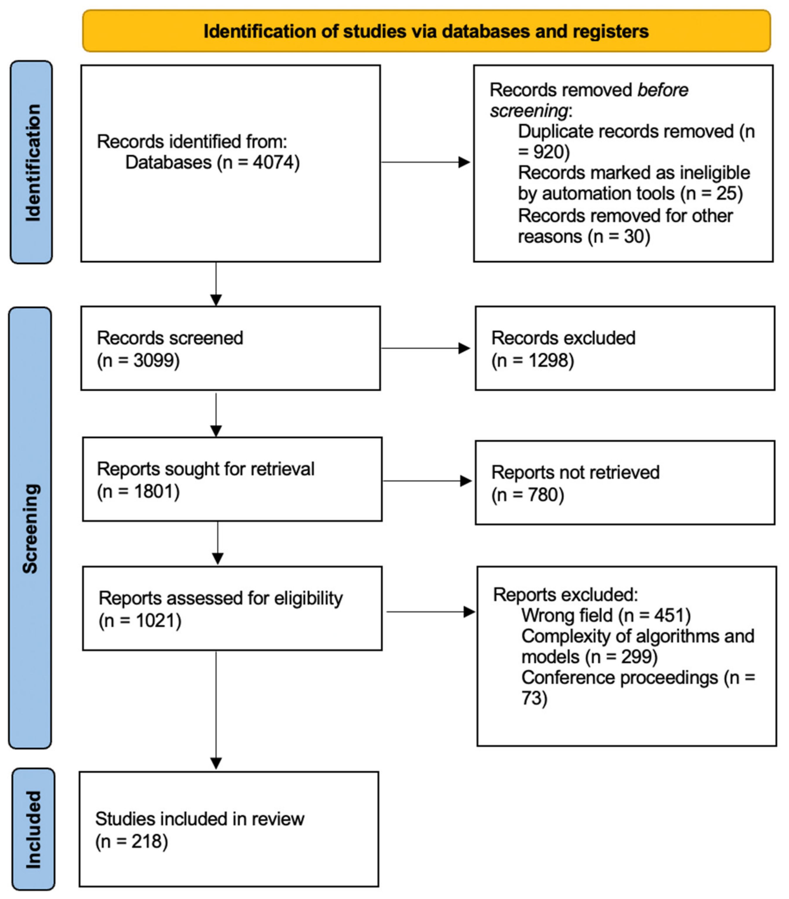
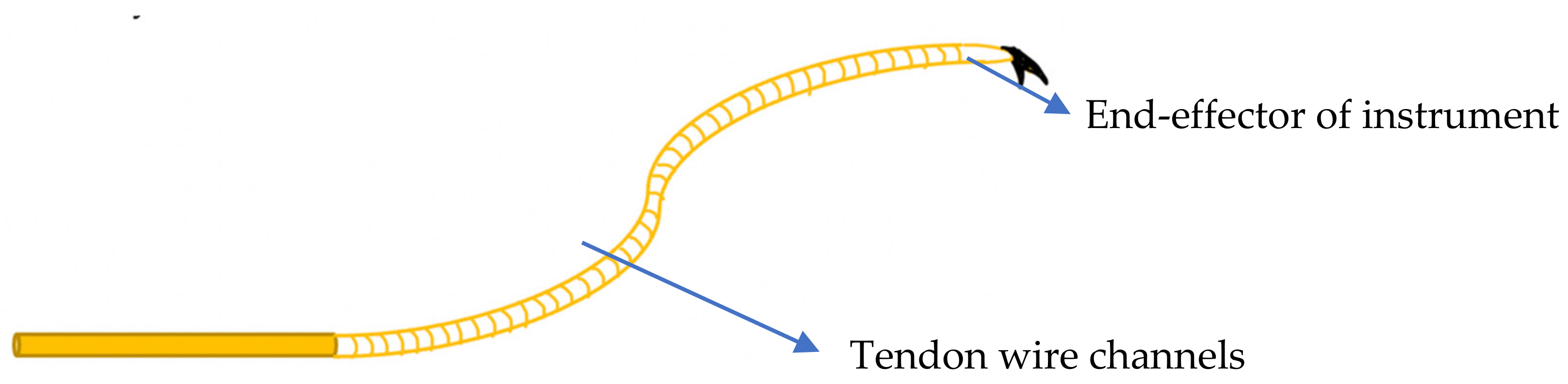
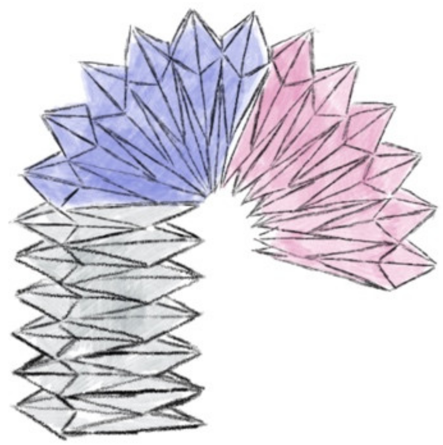
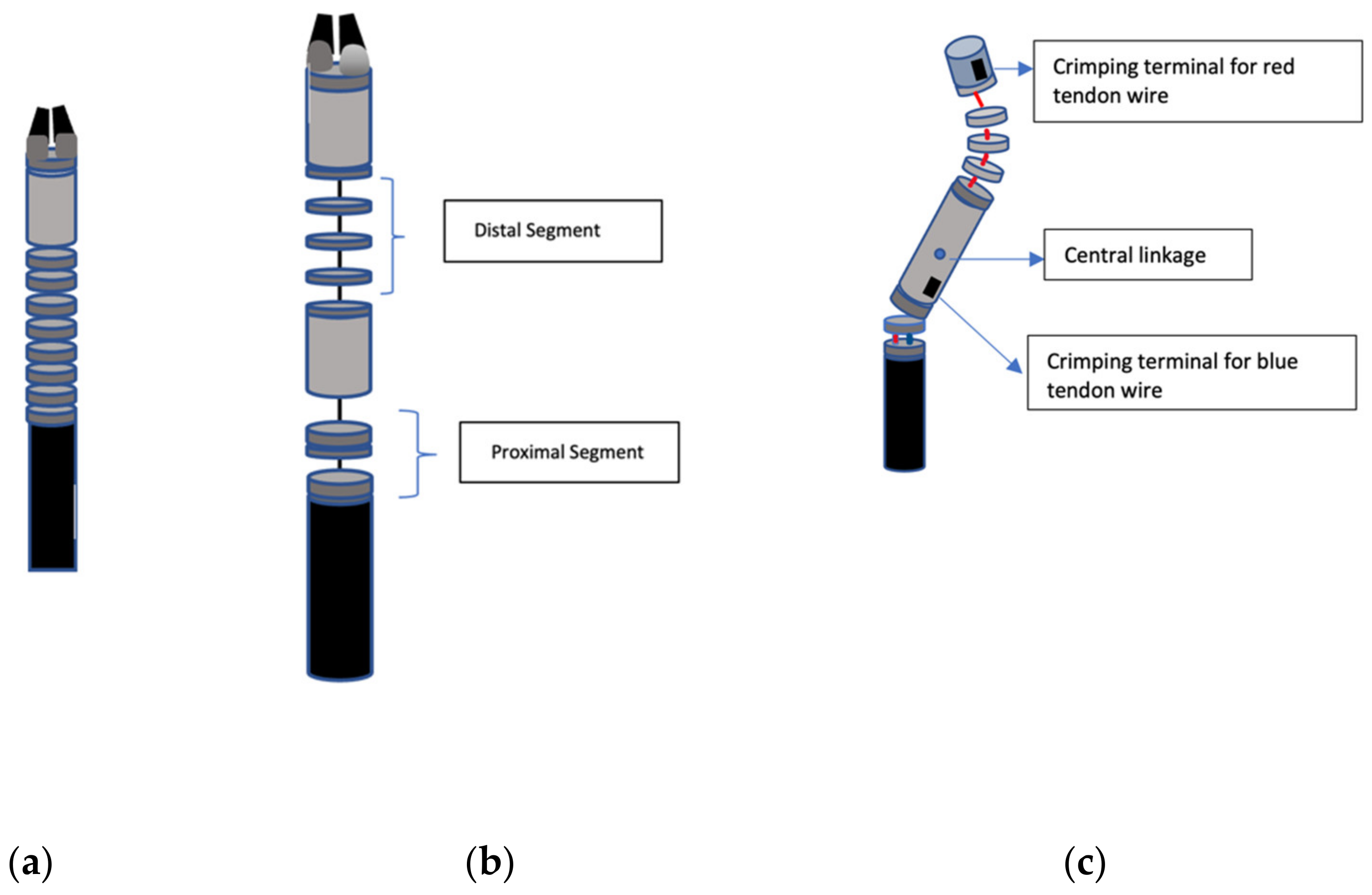
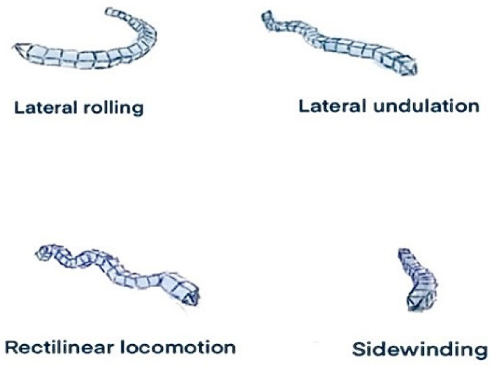
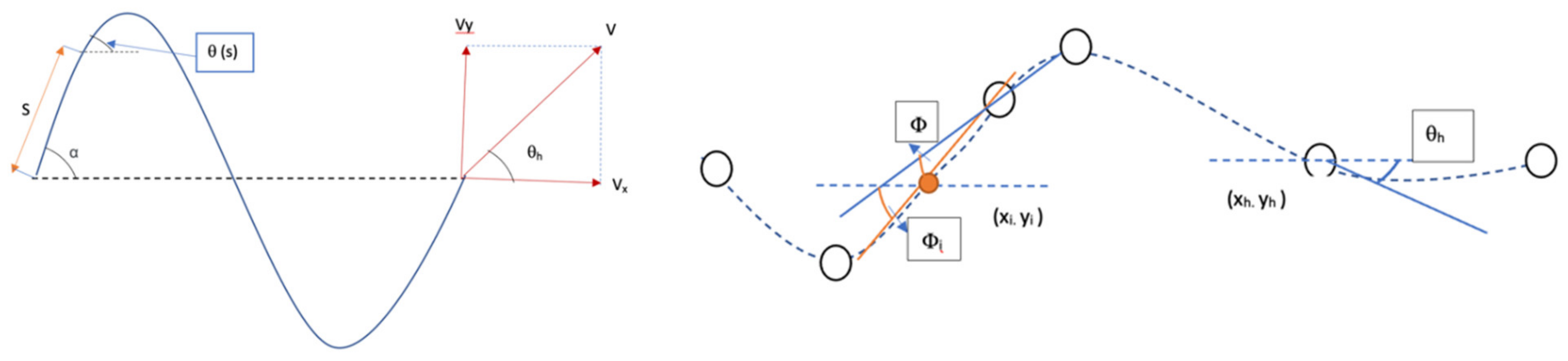
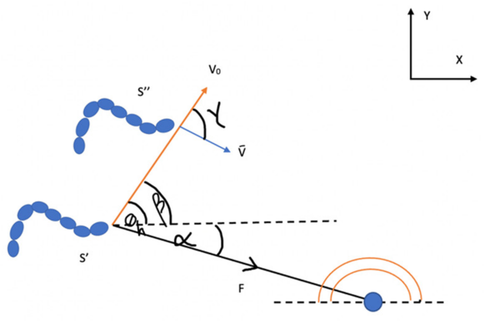
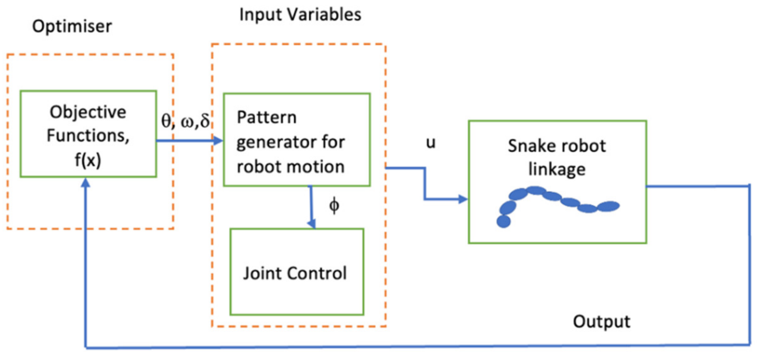
Table 1.
Existing robotic systems in the literature, classified in terms of the number of DOF and their functions.
Table 1.
Existing robotic systems in the literature, classified in terms of the number of DOF and their functions.
| Project Name | Author/Institute | Functioning Principle | Degrees of Freedom | Analysis Method |
|---|---|---|---|---|
| Telerobotic System for Minimally Invasive Surgery of the Throat | Simaan et al. [37] | Shortening and lengthening of circumferentially located NiTi backbones | 2 | Force sensing and kinematic modelling |
| I-Snake Surgical Robotic system | Shang et al. [38] | Interventions with the peritoneal cavity through a single orifice of 12.5 mm | 4 | N/A |
| CardioARM (Carnegie Mellon University) | Degani and Choset [27] | Multiple links strung together by cables actuated by conventional motors | Five for distal apparatus, 2 DOF for joystick | Variable stiffness in central cable tensioning, pose estimation and internal shape |
| Small snake-like robot for pipe inspection | Kuwada et al. [39] | Sinusoidal wave drive formed by coupling DC motors in series by rotational joints | N/R | Diameter variation analysis and its effect on movement |
| ACM-III robot | Hirose et al. [40] | Temporal and spatial motion for triggering locomotive recoil forces. Use of passive wheels along the body, with radio-servos for propulsion | 1 | Demonstrating Hirose’s serpenoid curve, use of tactile sensors for obstacle-aided locomotion |
| PIKo robot | Fjerdingen et al. [41] | Identical modules linked by two rotational joints, with wheels for forward and backward propulsion | 8 | Horizontal motion through bend, vertical climbing |
| Snake-like robot | Roh et al. [42] | Quad-tendon sheath mechanism and rolling joint control, associated with stereovision through 3D cameras | Two 7-DOF surgical tools, and a 5-DOF slave arm (14 in total) | N/A |
| Magnetic controlled snake robot | Tappe et al. [43] | Magnets were bevelled so that the joint could curve with angle commutation | N/R | N/A |
| Handheld flexible surgical robot | Ida et al. [44] | three linear motions and one rotational plane | 4 | N/A |
| Three-dimensional slithering snake-like robot | Bhatti et al. [45] | Three-dimensional autonomous locomotion—smooth slithering gait transition of speed, changing direction and body shape | N/R | CPG models based on convergence behaviour of the gradient |
| Approximate path-tracking snake robot | Tanaka M et al. [46] | Path tracking, the robot can switch the wheels that touch the ground by lifting the required parts of its body | N/R | N/A |
| CMU modular snake robot | Ponte et al. [47] | Maps remote 3D environments, pole climbing and pipe navigation with structured light sensors | N/R | Three-dimensional point clouds used to provide external data when locating obstacles in planning and operation |
| A continuum robot based on the origami structure | Santoso et al. [48] | The driving force of the motor consists of four wires passing through the origami space | N/R | Inverse kinematics of the manipulator for path following and lower vibrations with grow-to-shape equations |
| Aiko robot | Transeth et al. [49] | Portable DC motor-operated platform | N/R | Rough surface dynamics and convex analysis with stick–slip transitions |
| MOIRA | Osuka and Kitajima [50] | Actuated by pneumatic cylinders, with two longitudinal tracks for each side | 2 | N/A |
| OSMOS snake | Singh et al. [51] | Use of sphere-shaped modules to locomote the snake structure without changes in shape | N/R | N/A |
| Millibot train (Carnegie Mellon University) | Brown et al. [52] | Couplers ensure active connection and disconnection of segments, lifts three proximal segments | 1 | N/A |
| OmniTread | Armada et al. [53] | Pneumatic actuation for surface terrain compliance and shock absorption | 2 | Position and stiffness variation by bellow-shaped actuators |
Publisher’s Note: MDPI stays neutral with regard to jurisdictional claims in published maps and institutional affiliations. |
© 2022 by the authors. Licensee MDPI, Basel, Switzerland. This article is an open access article distributed under the terms and conditions of the Creative Commons Attribution (CC BY) license (https://creativecommons.org/licenses/by/4.0/).
Share and Cite
MDPI and ACS Style
Seetohul, J.; Shafiee, M. Snake Robots for Surgical Applications: A Review. Robotics 2022, 11, 57. https://doi.org/10.3390/robotics11030057
AMA Style
Seetohul J, Shafiee M. Snake Robots for Surgical Applications: A Review. Robotics. 2022; 11(3):57. https://doi.org/10.3390/robotics11030057
Chicago/Turabian StyleSeetohul, Jenna, and Mahmood Shafiee. 2022. "Snake Robots for Surgical Applications: A Review" Robotics 11, no. 3: 57. https://doi.org/10.3390/robotics11030057
Note that from the first issue of 2016, this journal uses article numbers instead of page numbers. See further details here.