
Proposal of a New Double-Nozzle Technique for In-Gas-Jet Laser Resonance Ionization Spectroscopy


Facility for Antiproton and Ion Research in Europe (FAIR), Planckstraße 1, 64291 Darmstadt, Germany
Atoms 2023, 11(6), 88; https://doi.org/10.3390/atoms11060088
Submission received: 12 April 2023
/
Revised: 23 May 2023
/
Accepted: 26 May 2023
/
Published: 28 May 2023
(This article belongs to the Section Atomic, Molecular and Nuclear Spectroscopy and Collisions)
Abstract
:This paper proposes a new double-nozzle technique for in-gas-jet laser resonance ionization spectroscopy. We explored the functionality of this new technique through detailed gas dynamic and Monte Carlo atom-trajectory simulations, in which results are presented and discussed. The results of similar computer simulations for JetRIS setup (as a typical representative of the conventional in-gas-jet technique nowadays) are also presented and discussed. The direct comparison of calculation results for the proposed new technique with the conventional one shows that the double-nozzle technique has many advantages compared with the one used in the JetRIS setup at GSI for future high-resolution laser spectroscopic study of heaviest elements. To fully implement the proposed new technique in all existing (or under construction) setups for in-gas-jet laser resonance ionization spectroscopy, it will be enough to replace the used supersonic nozzle with the miniature double-nozzle device described in the paper.
1. Introduction
For the studies of nuclear, atomic and chemical properties of radioactive elements, different techniques using gas-stopping cells are conventionally used. The primary energetic radioactive ions are injected into a gas cell filled with the high-purity buffer gas (usually helium or argon) by passing through a thin entrance window. Due to a number of their collisions with buffer gas atoms, ions decelerate down to the gas flow velocity and are thermalized. To speed up the transport of ions through big-sized gas cells, a DC gradient electric field is applied. In this case, the ion velocity is determined as a product of the applied electric field in [volt cm−1] and the ion mobility coefficient in [cm2 sec−1 volt−1].
Near the extraction nozzle with a small throat diameter, ions are extracted from the gas cell into vacuum conditions by a supersonic buffer gas jet. Description of various gas cell apparatus readers can find elsewhere, for example, in [1,2,3,4,5,6,7,8,9,10,11,12,13,14,15,16,17,18,19] and links within them.
The extraction of the ions into a high vacuum is finally performed with the use of radiofrequency quadrupoles (RFQ) [7,8,11,20,21,22,23,24,25,26] or radio-frequency sextupoles (SPIG) [9,15] installed downstream for the ion beam transportation and focusing. Instead of traditional RFQ and SPIG rod structures, simple, compact, and effective gas dynamic RF-only funnels can also be used. The review of the RF-only funnel technique can find in our recent work [27].
The other way to investigate the nuclear and atomic properties of radioactive elements extracted from the gas cell is by using laser spectroscopy techniques. One can read about, e.g., recent reviews [28,29] and presentation reviews of Piet Van Duppen [30].
The most attractive and promising method of laser spectroscopy for studying the properties of radioactive elements is the so-called method of in-gas-jet laser resonance ionization spectroscopy that was first proposed and experimentally tested in KU Leuven [31]. Briefly, it consists of the following. Under the applied DC electric field gradient, the thermalized in the high purity argon ions are transported through the gas cell and focused on the tip of the metallic hot filament. The tip of the filament has been installed on the axis of the exit flow channel in front of the nozzle. After collecting ions on the filament and their thermal evaporation as neutral atoms, they are transported by only the carrier gas flow through the converging-diverging nozzle into the vacuum gas-jet chamber. Two lasers in cross-beam geometry perform the high-resolution and efficient resonance excitation and ionization of the extracted into the gas-jet chamber neutral atomic beam. One laser beam (we will refer to as a Laser-1) directed along the axis upstream of the gas flow direction excites atoms of interest, and the second one (we will refer to as Laser-2) directed perpendicular to the gas jet ionizes these excited atoms. Then the ionized by the Laser-2 atoms are transported as the ion beam by the carrier gas jet to the bent RFQ (e.g., S-shaped [31] or bend 90 degrees [32]). This curved RFQ allows for the axial laser beam injection into the gas jet and differential vacuum pumping. One can find the schematics and descriptions of various setups for the in-gas-jet laser resonance ionization spectroscopy, e.g., in Refs. [29,30,31,32,33,34,35,36,37,38].
The article has two following goals.
The first goal—is a detailed quantitative study of the atomic beam extraction from the gas-stopping cell and then its formation and cooling in the supersonic argon gas jet under the described above traditional approach to the in-gas-jet resonance ionization laser spectroscopy. As a typical representative for this study, we have chosen the experimental gas-jet apparatus [32,33] recently created for high-resolution laser spectroscopy of the heaviest elements at the Separator for Heavy Ion Reaction Products (SHIP) at GSI, Darmstadt. This project, called JetRIS, is under development at GSI.
The second goal—is the proposal and detailed exploration of a new double-nozzle technique for its application in gas-jet resonance ionization laser spectroscopy.
We have reached both goals through computer experiments, which consisted of detailed gas dynamic and atom-trajectory Monte Carlo simulations, which results in we present and discuss below in the next sections. First, in the dynamic gas simulations of the buffer gas flow inside the gas cell and the supersonic argon carrier gas jet, we used the VARJET code. This code is based on the solution of a full system of time-dependent Navier–Stokes equations and is described in detail in [39]. The results of the gas dynamic simulations (flow fields of the buffer gas velocity, density, and temperature) we then used in atom-trajectory Monte Carlo simulations.
Similar computer simulations were also made earlier for different ion beams cooling and bunching in helium buffer gas flows, and their results are presented elsewhere (e.g., see [17,18,19,40,41,42,43,44,45,46,47,48]). Note that our calculation results (gas dynamic + Monte Carlo) for ions extracted from the gas jet into a vacuum are in good agreement with the measurements (see, e.g., [43,44]). Based on our gas dynamic calculations, setups of gas-jet internal targets [49,50] have been created. These calculations are in good agreement with the measured parameters and structure of the supersonic gas jets, as well.
For simplicity, in comparison of the two mentioned above in-gas-jet techniques, the conventional one, which is used in the project JetRIS, we will refer below to as a “GSI nozzle” and the proposed here new technique as a “double-nozzle”.
2. Results for GSI Nozzle
Three different nozzles, which cross-sectional profiles are shown in [33] (see Figure 3 there), were used at the JetRIS setup in offline test measurements of neutral 164Dy atoms fluorescence induced by one-step laser excitation. All these nozzles have the same throat diameter of 1 mm but different lengths and contours of diverging supersonic parts. The authors of [33] note that these three nozzles were designed for different stagnation pressure in the gas cell (Pcell) and background pressure (Pbg) in the vacuum chamber of the gas jet expansion, which we will refer to as a gas-jet chamber. The sophisticated contours of the left and right nozzles, shown in Figure 3 of Ref. [33], were designed (Ref. [35]) and produced in KU Leuven, but due to the lack of exact information available to us about these nozzle’s profiles, we could not use these two nozzles in our gas dynamic simulations. Contrary, the third nozzle, which shown in the middle of Figure 3 of Ref. [33], and referred to as the “mid-range nozzle”, has a simple conical diverging part with a length of 20 mm, throat diameter of 1 mm and exit diameter of 6.6 mm.
The authors of the work [33] note, “The mid-range nozzle seems to be the best overall choice since its resolution and homogeneity are both close to the optimal values found for the other two nozzles”. This is an additional reason why we chose this particular nozzle for a detailed computer study of the operation of the JetRIS setup.
The gas dynamic simulation we have performed for the argon stagnation pressure in the gas cell Pcell = 100 mbar and background pressure in the vacuum gas-jet chamber is Pbg = 6.47 × 10⁻³ mbar. The same pressure values were in the JetRIS setup during test fluorescent measurements of neutral 164Dy atoms inside the supersonic argon jet (see Table 1 and the Figure 4 caption in [33]).
2.1. The Exit Flow Channel
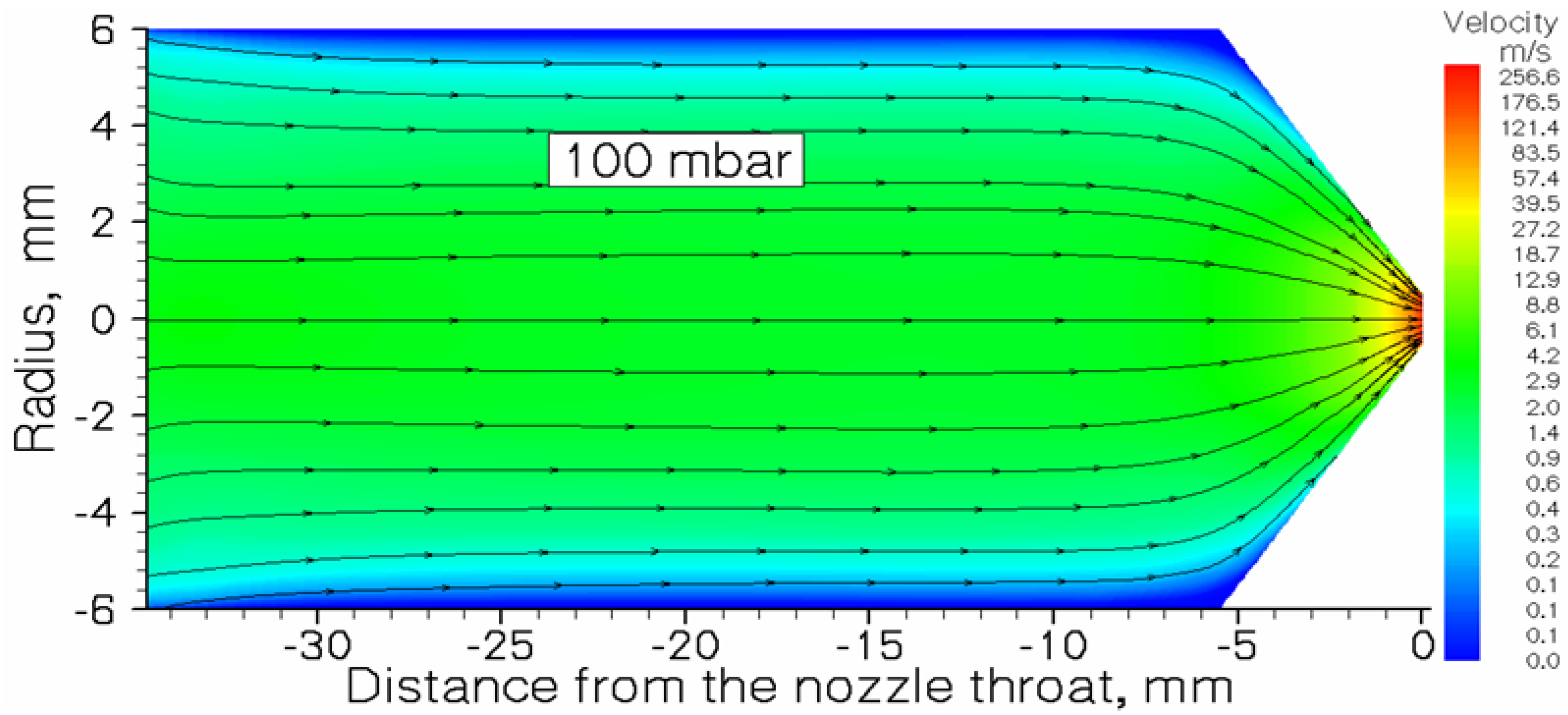
The JetRIS gas cell technical drawing is shown in the left part of Figure 5 in [32]. The inner diameter of the gas cell DC-cage is 160 mm, with a length of 164.5 mm. The total length of the DC funnel (five electrodes having gradually decreasing diameters) placed behind the DC cage is 63.5 mm. The exit flow channel between the DC funnel and the nozzle has a diameter of 12 mm and a length of 34.6 mm. Due to the large diameter of the DC-cage (160 mm) and only 1 mm of the nozzle throat diameter, the average velocity of the gas flow inside the DC-cage is only about 8 mm/s. That is why it is necessary to use the DC gradient field inside the cell to speed up the transport of the decelerated radioactive ions.
Early, we were making detailed (gas dynamic + Monte Carlo) simulations for different big-sized gas-stopping cells [6,17,18,19]. E.g., the results of our simulations for the UNICELL project [51], which is also under development at GSI, presented in [17]. But here, we should notice that simulations of the 164Dy ions transport through the main body of the JetRIS gas cell having an inner diameter of 160 mm to the hot filament installed inside the exit flow channel have been carefully done by the authors of [32]. Therefore, it does not make much sense to repeat it, and we decided to start our gas dynamic simulation from the entrance to this exit flow channel (12 mm in diameter), where the average gas velocity is a factor of 178 higher than it is inside the DC-cage region. Notice that the evaporated from the surface of hot filament neutral atoms are moving through the exit flow channel and then through the nozzle into the vacuum gas-jet chamber only under the effect of the gas flow.
Monte Carlo atom-trajectory simulations began from the filament tip, where neutral 164Dy atoms first appear in the gas flow after evaporation. From the technical drawing presented in [32] we determined that the filament in the JetRIS setup has been installed at about 22.5 mm from the nozzle.
Results of the gas dynamic simulation for the gas velocity flow field inside the exit flow channel are shown in Figure 1.
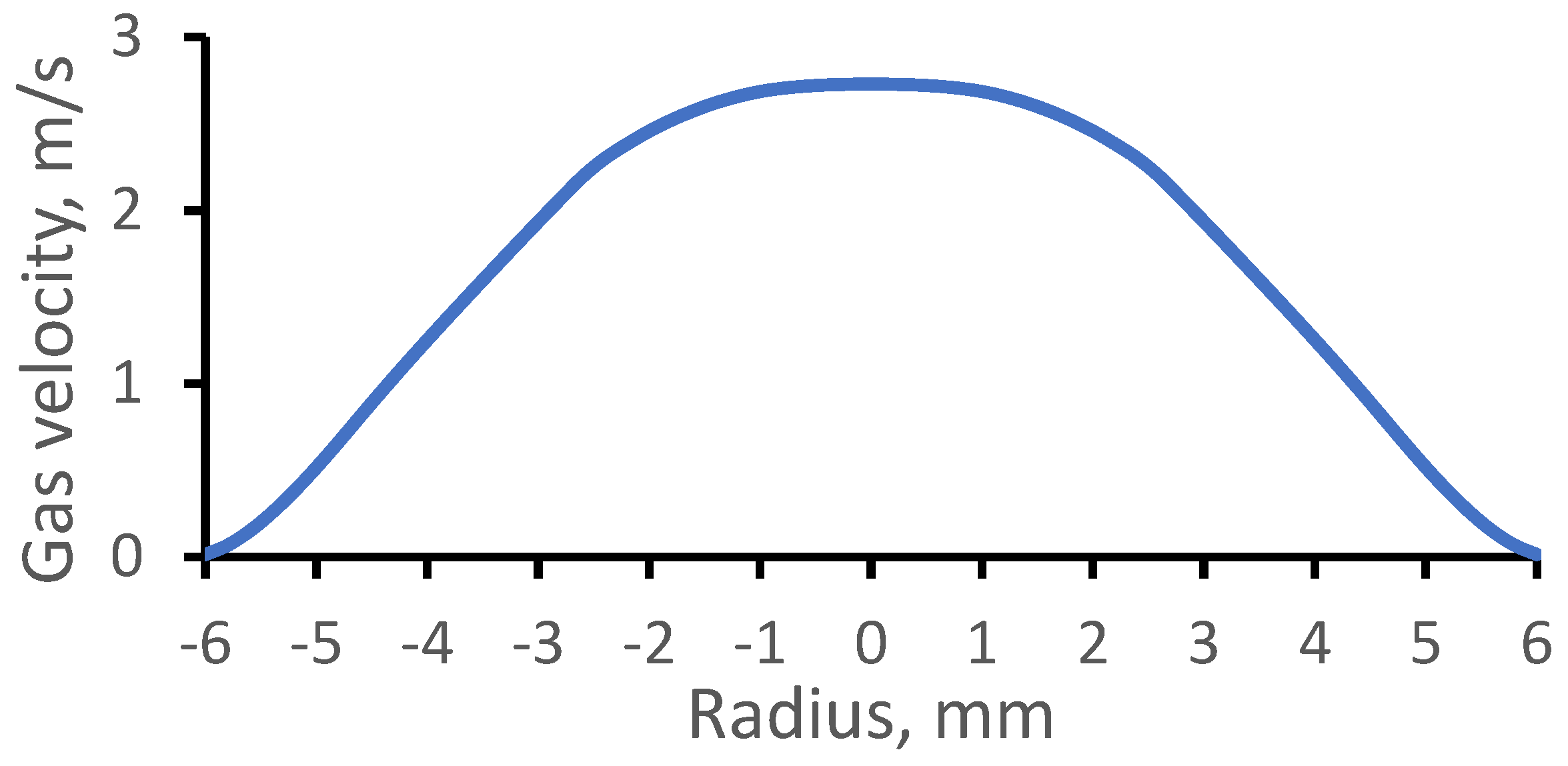
Figure 2 shows the radial gas velocity profile in the middle of this exit flow channel. The parabolic gas velocity profile, typical for the laminar viscous gas flow inside a tube, is visible. The corresponding Reynolds number is equal to 123.
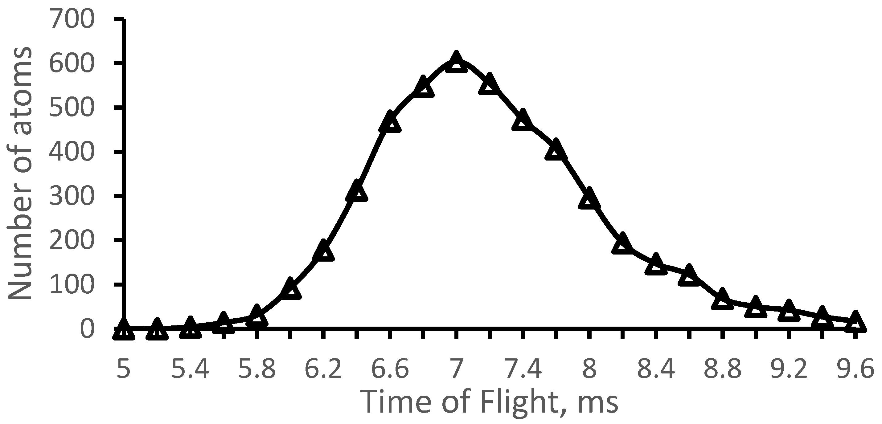
Calculation results for the time-of-flight distribution 164Dy atoms from the filament tip to the nozzle throat are shown in Figure 3. The average atoms’ extraction time is T = 7.0 ms, and the time spread determined as the full width at half maximum (FWHM) is ΔT = 1.4 ms. The corresponding extraction efficiency of 164Dy atoms from the exit flow channel is 94.5 ± 2.7%.
2.2. GSI Nozzle at Gas Cell Pressure Pcell = 100 mbar and Pbg = 6.47 × 10⁻² mbar
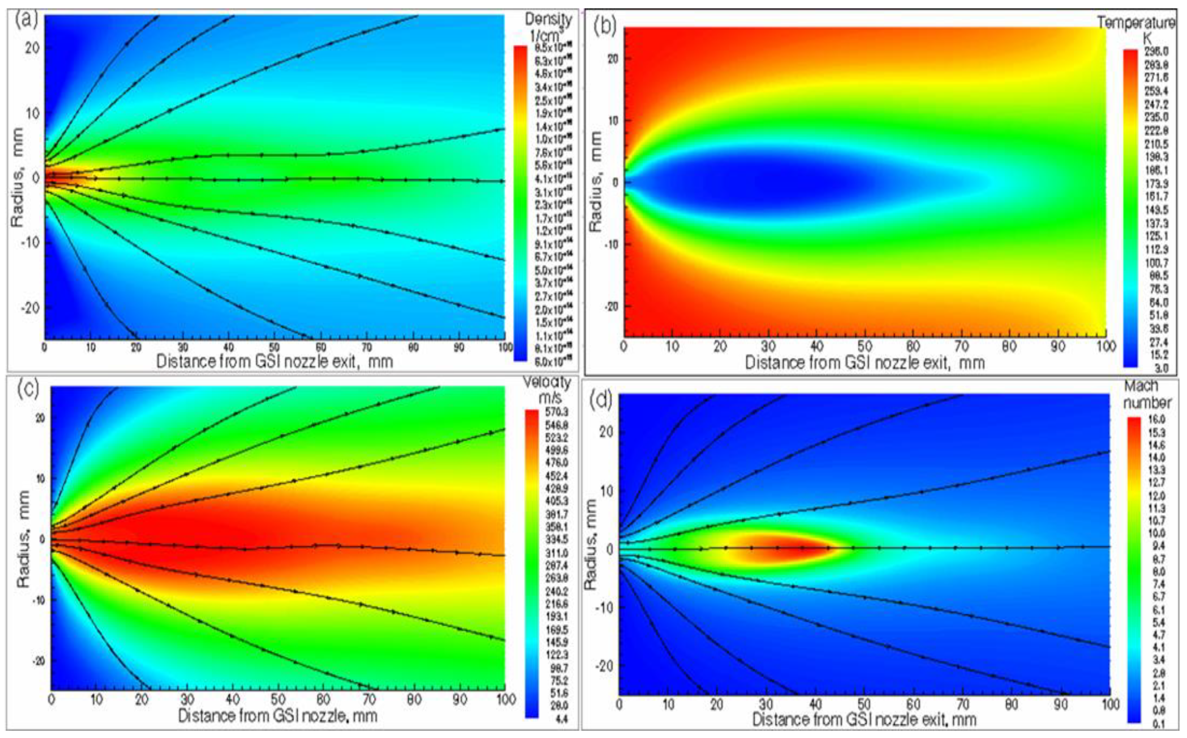
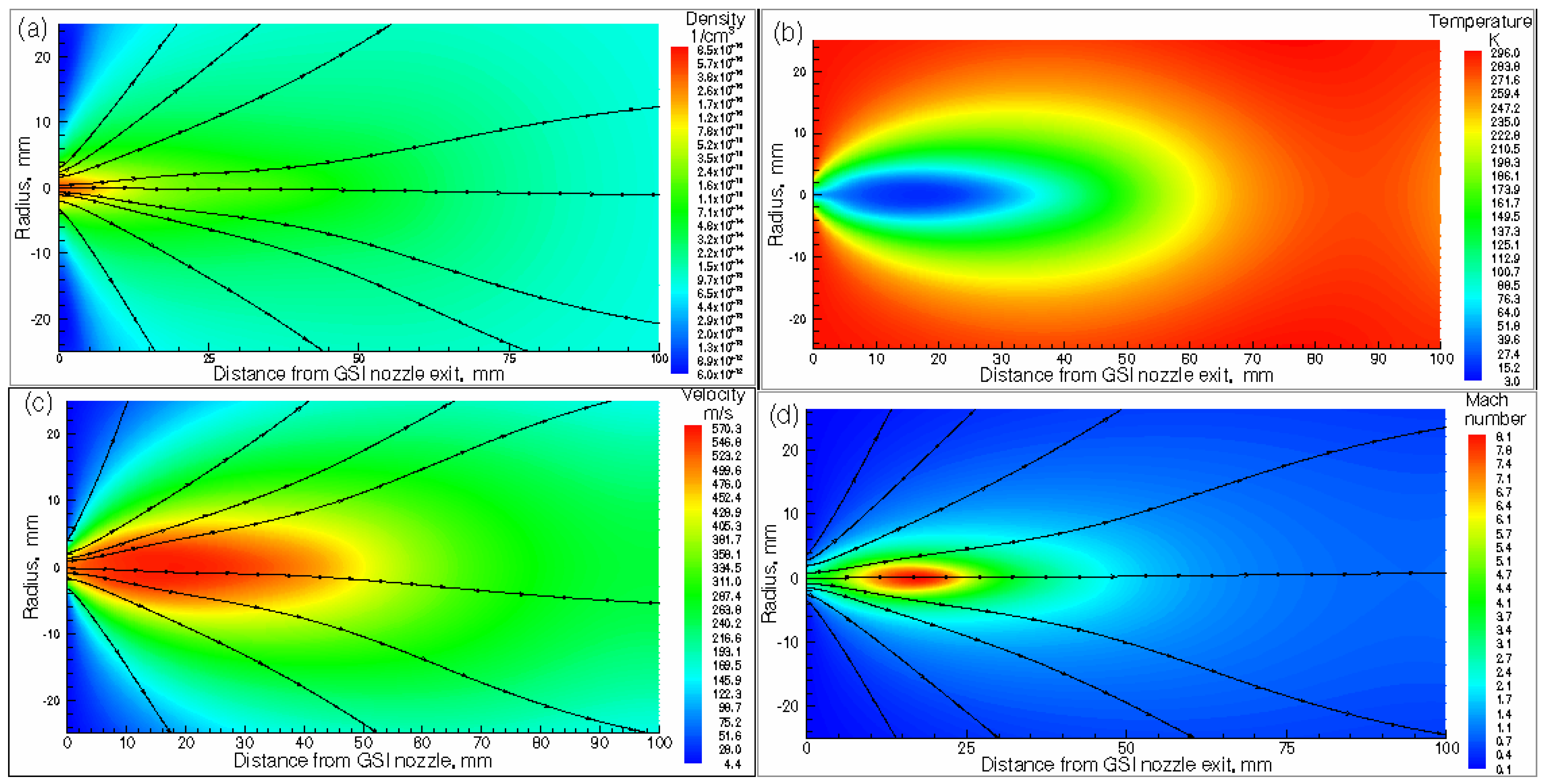
Results of the gas dynamic simulation for argon gas density, temperature, velocity, and Mach number flow fields for the GSI nozzle are shown in Figure 4.
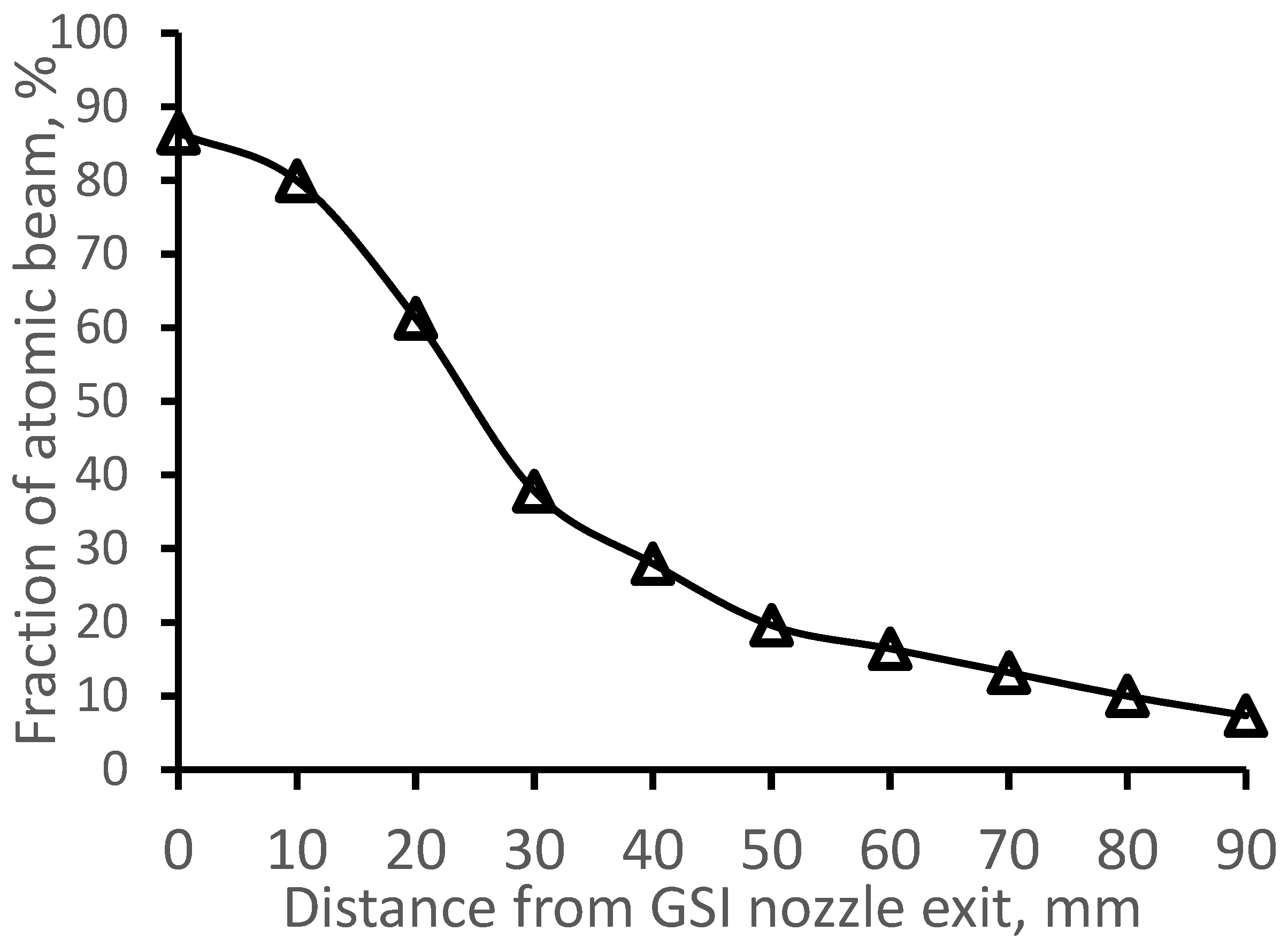
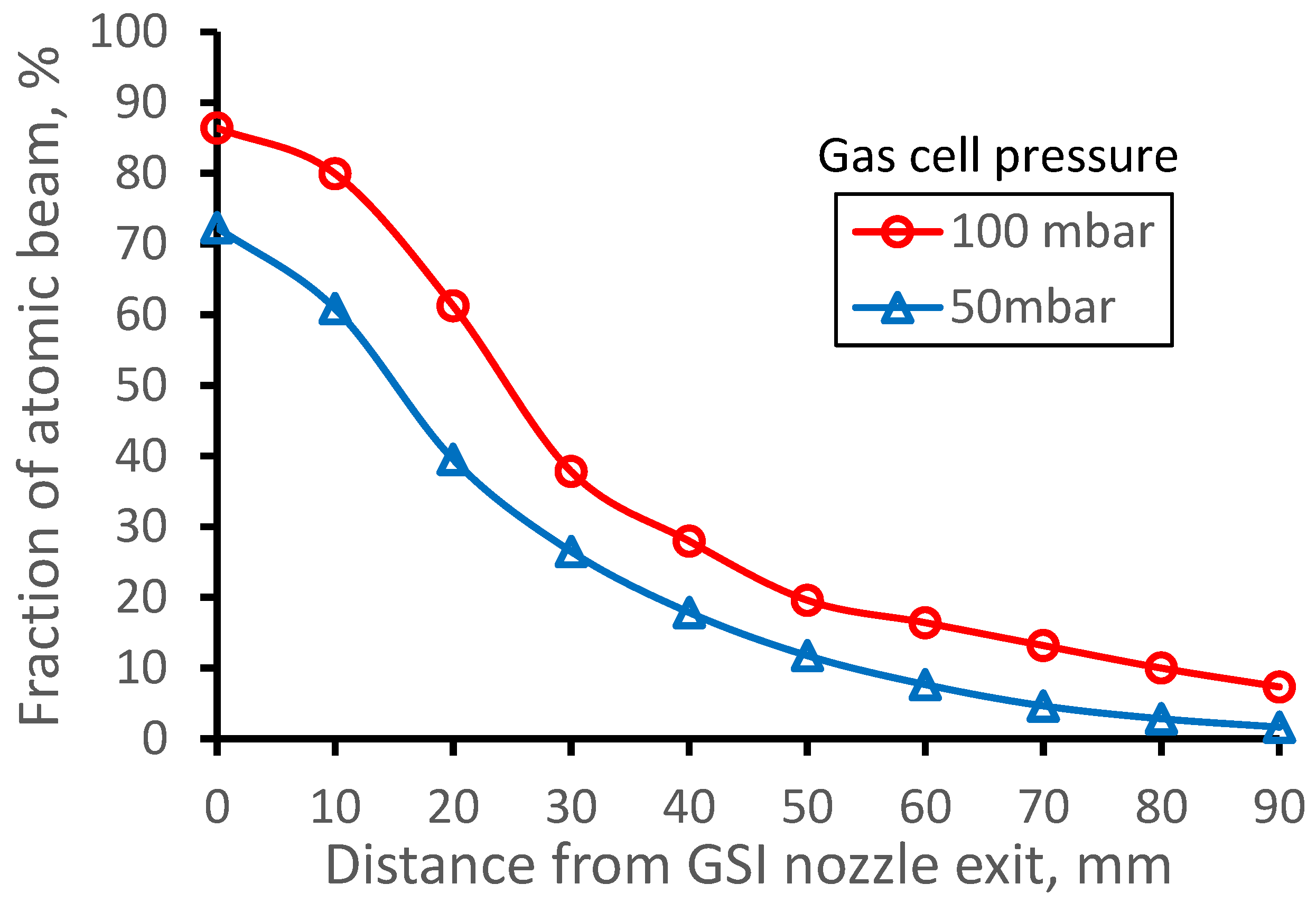
We have used the results of the gas dynamic simulation shown in Figure 4 for Monte Carlo simulations of the 164Dy atomic beam. These results are presented in the next four Figures. The calculated fraction of the extracted from the gas cell 164Dy atomic beam inside the region of 10 mm (the Laser-1 diameter in [33]) as a function of distance from the GSI nozzle exit is shown in Figure 5. The decrease of the dysprosium atomic beam fraction with the distance from the GSI nozzle is simply explained by the gas jet divergence. The atomic beam diffusion losses inside the GSI nozzle are equal to 15.6 ± 0.6% and are considered in the data presented in Figure 5.
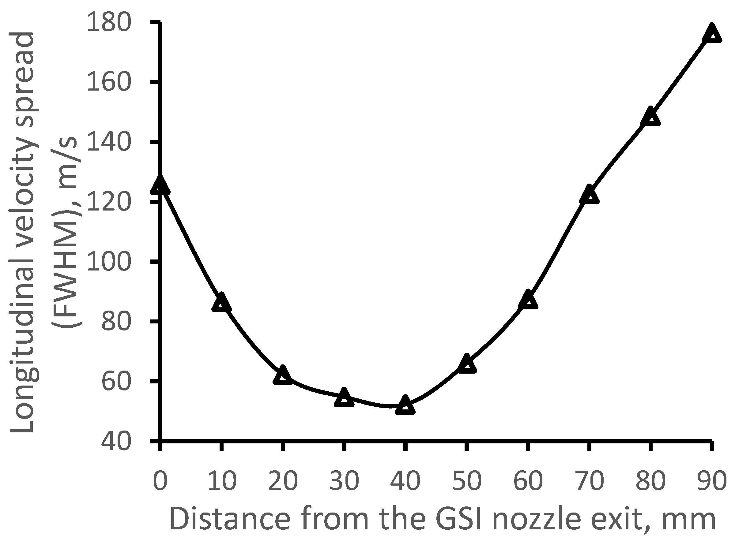
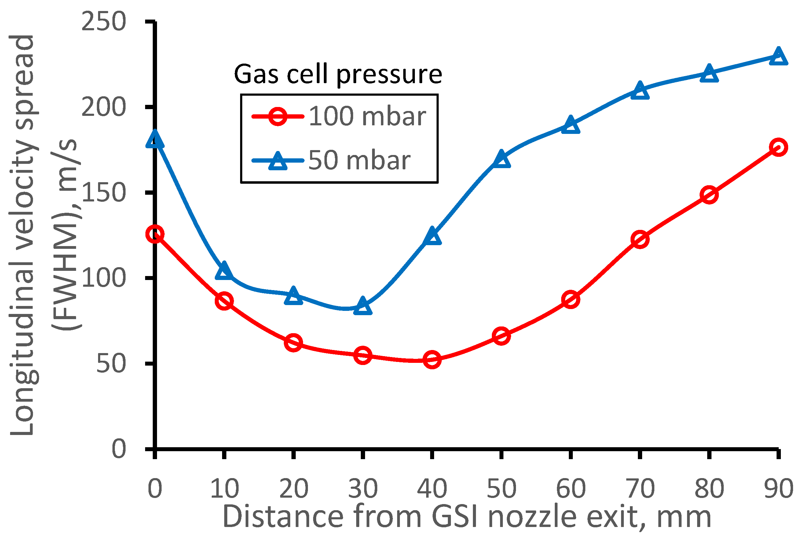
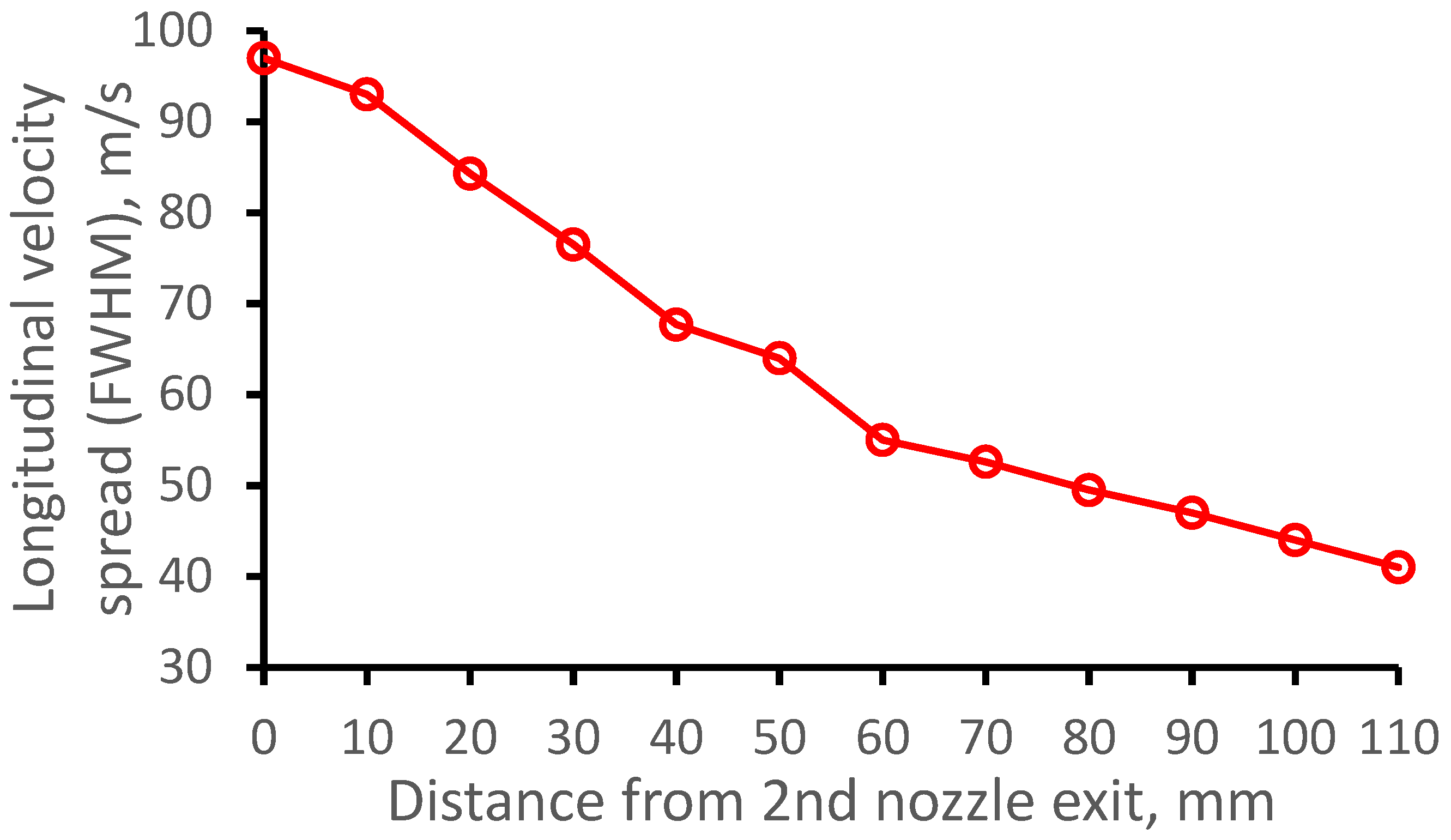
Figure 6 demonstrates how the calculated longitudinal velocity spread of the dysprosium atomic beam depends on the distance from the GSI nozzle. The data averaged in the radial plane over the Laser-1 beam diameter makes it possible to compare our calculations directly and simply with future experiments at the JetRIS setup. Moreover, such calculations allow for getting crucial quantitative information on the quality of the cooled in the supersonic gas jet atomic beams.
2.3. GSI Nozzle at Gas Cell Pressure Pcell = 50 mbar and Pbg = 3.23 × 10⁻² mbar
To check how the supersonic gas jet structure and parameters extracted into the jet 164Dy atomic beam will look at lower stagnation gas cell pressure, we performed calculations, which are similar to the calculations described above in Section 2.2 for the same pumping capacity, but for the gas cell pressure of Pcell = 50 mbar. The results of the gas dynamic simulation for argon gas density, temperature, velocity, and Mach number flow fields for the GSI nozzle at Pcell = 50 mbar are shown in Figure 9.
Results of the Monte Carlo simulations for the case of 50 mbar gas cell pressure are shown in Figure 10 and Figure 11. In addition, we have included the results of calculations presented above in Figure 5 and Figure 6 for the case of Pcell = 100 mbar for comparison. Notice that the atomic beam diffusion losses inside the GSI nozzle at Pcell = 50 mbar are equal to 27.7 ± 0.8%, about factor 2 higher than that at Pcell = 100 mbar.
3. Results for Double-Nozzle Technique
3.1. Historical Notes
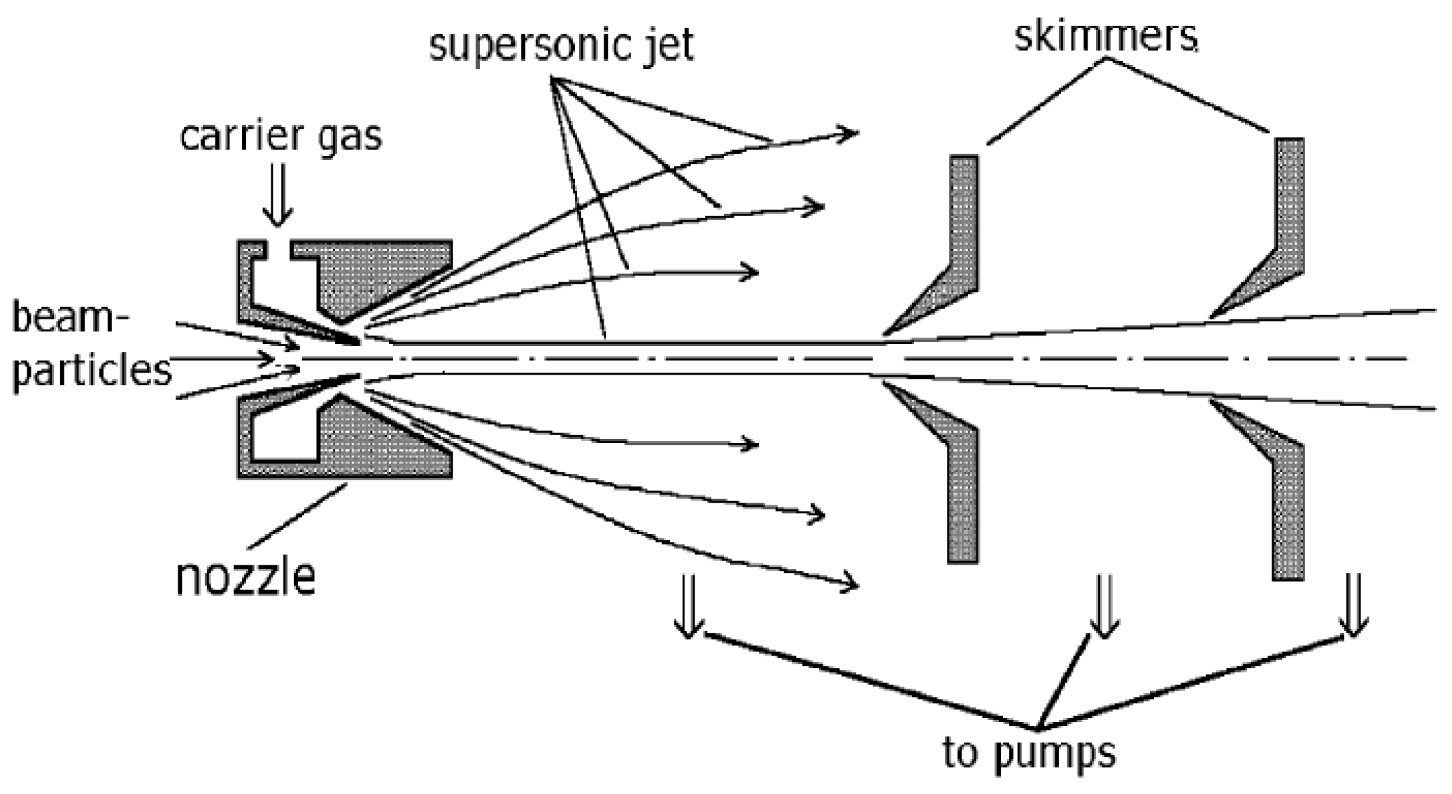
The new double-nozzle technique for in-gas-jet resonance ionization laser spectroscopy we propose here is based on gas dynamic cooling of low-energy molecular and ion beams. This idea was proposed for the first time in 1979 [52,53] and described also, e.g., in [5,39,54,55,56,57,58,59,60,61]. It consists of direct injection of primary beams into supersonic carrier gas jet using a specially designed supersonic nozzle. The converging–diverging supersonic nozzle has a narrow inner tube on its axis which passes through a gas stagnation chamber into a region of supersonic carrier gas expansion (see Figure 12). Then, this inner tube particle of interest is injected into the expanded supersonic gas jet. A low-pressure zone forms immediately after the tube, so this supersonic carrier gas jet acts as a vapor-jet pump. It provides for the possibility of effective differential pumping in the case of ion beam injection [60].
To show the feasibility and effectivity of the described gas dynamic method experimentally. A gas dynamic molecular beam source setup was constructed in the middle of the 1980s at the Leningrad Nuclear Physics Institute (LNPI) in Gatchina [56,57]. As a result of experimental investigations, it has been obtained the effective cooling of hot lead iodine (PbI) molecular beam in the supersonic nitrogen jet from 900 K down to 20 K was an essential part of our PhD work [54]. Notice that the two-atomic molecules PbI are free radicals produced via the thermal decomposition of three-atomic molecules PbI2 inside the separately heated thin quartz capillary installed into the inner tube of the supersonic nozzle shown in Figure 12.
The description and schematic layout with photos of some parts of this gas dynamic molecular beam source setup in LNPI one can find in our presentation at Institute for Medium Energy Physics (IMEP) (renamed after 2004 to “Stefan Meyer Institute” (SMI)), Vienna [61].
3.2. Double-Nozzle Design
To implement the proposed here double-nozzle technique for in-gas-jet laser resonance ionization spectroscopy, it is sufficient to connect the short conical convergent-divergent nozzle of the gas cell, which we will call the 1st nozzle, with the 2nd nozzle, which designs schematically shown in Figure 12.
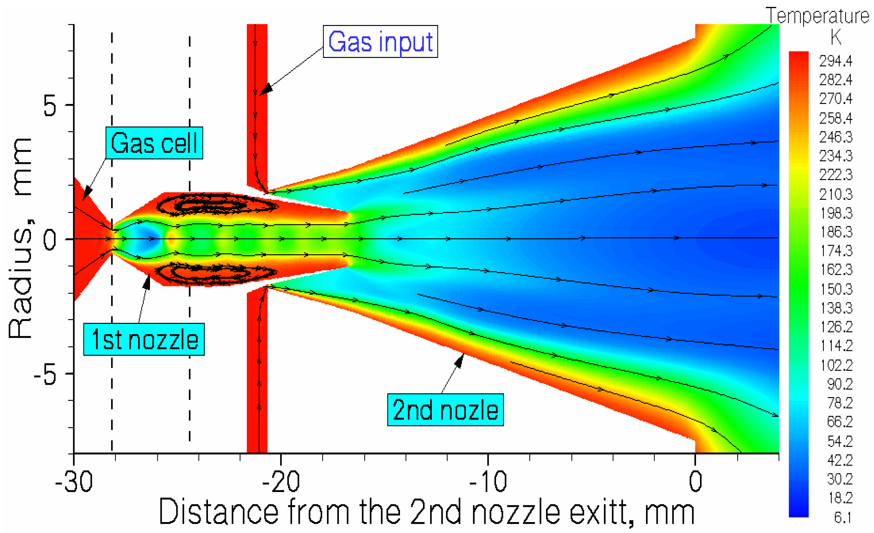
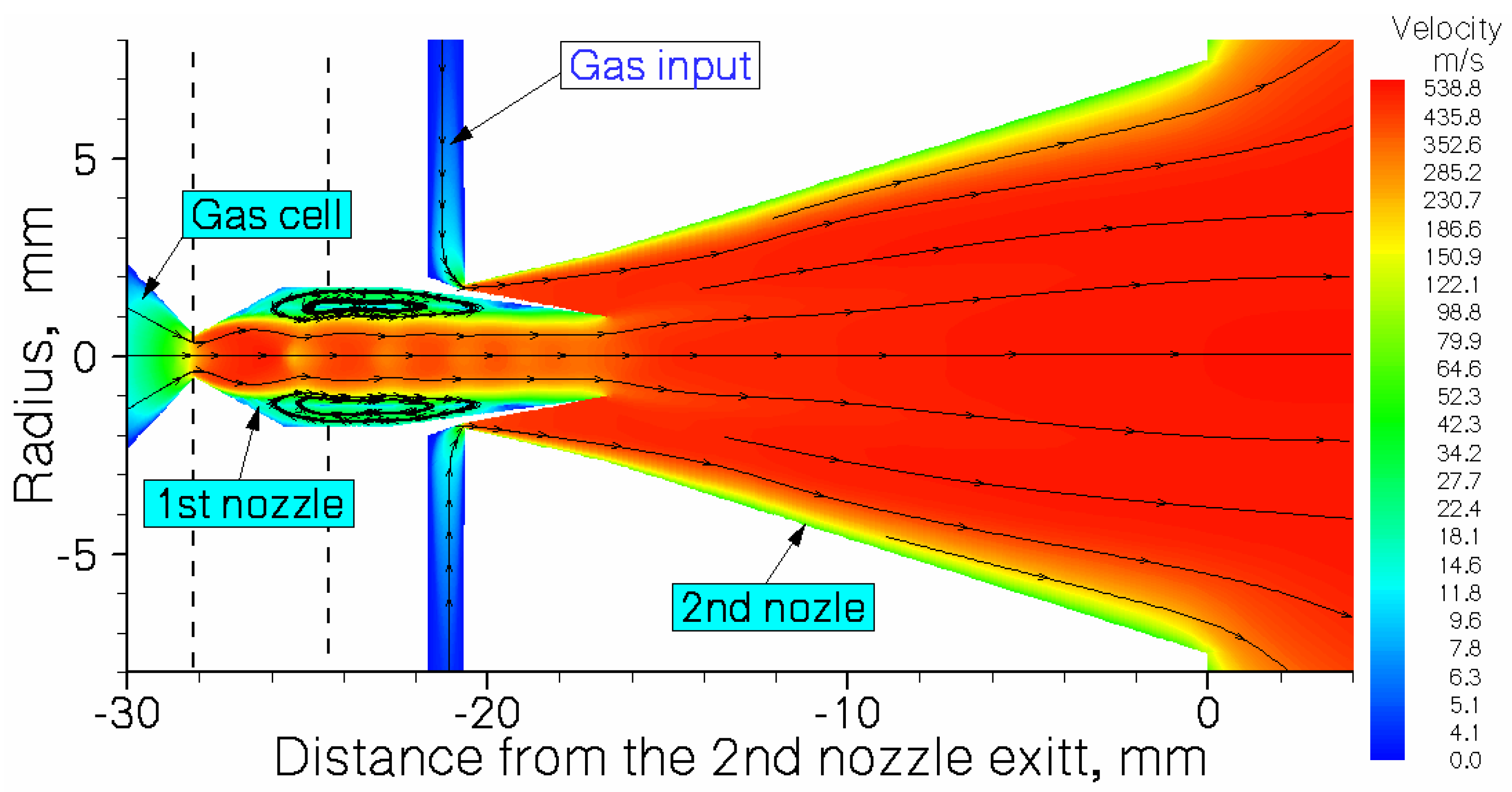
Schematic views of the double-nozzle design combined with results of the gas dynamic simulation for argon temperature and velocity flow fields are shown in Figure 13 and Figure 14, correspondingly.
A gas vortex that one can see in Figure 13 and Figure 14 appears in the region between the 1st nozzle throat and the exit of the inner tube in the 2nd nozzle due to the viscous gas jet interaction with the walls. This vortex around the supersonic jet flowing out of the gas cell protects the dysprosium atoms from hitting the walls, thus reducing the diffusion losses of the neutral atomic beam extracted from the gas cell. The result of the Monte Carlo calculation shows that only 9.5 ± 0.4% of the removed from the gas cell atomic beam is lost inside this double-nozzle device.
The main design parameters of the double-nozzle device used in simulations are listed in Table 1.
3.3. Double-Nozzle at Pcell = 100 mbar, Pnoz = 81 mbar and Pbg = 2 × 10⁻² mbar
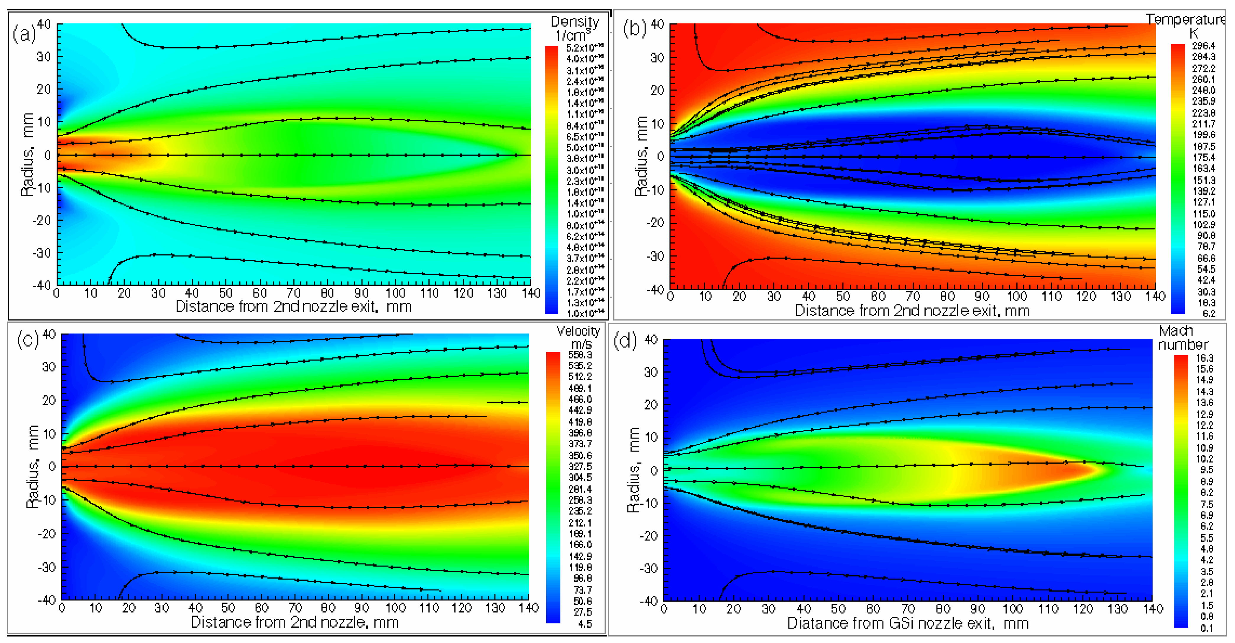
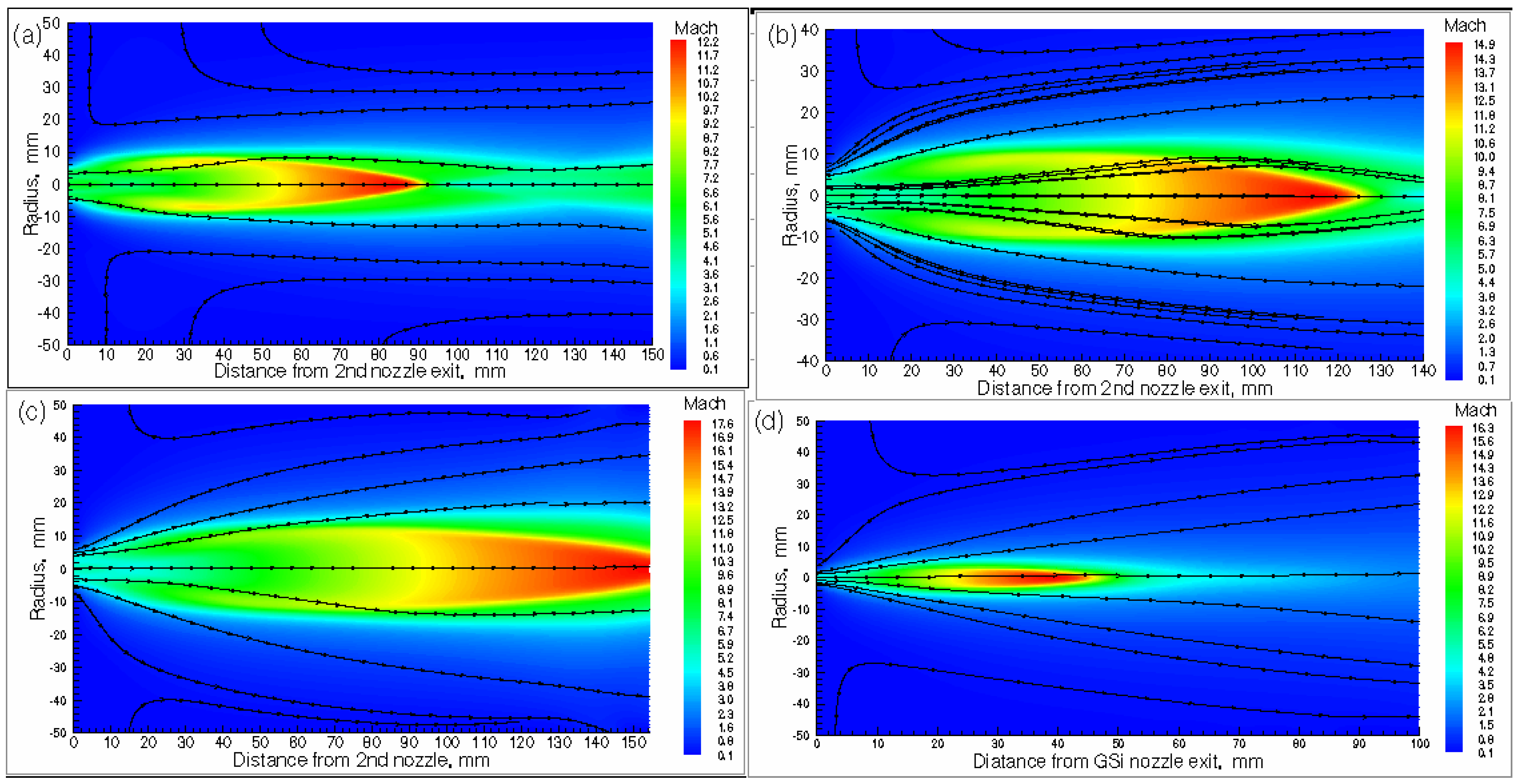
Results of the gas dynamic simulation for argon gas density, temperature, velocity, and Mach number flow fields for the double-nozzle are shown in Figure 15.
3.4. Effect of the Pumping Speed
To investigate the effect of the pumping speed on the 164Dy atomic beam parameters in the supersonic gas jet at fixed stagnation pressures Pcell = 100 mbar, Pnoz = 81 mbar, we have made corresponding gas dynamic and Monte Carlo simulations.
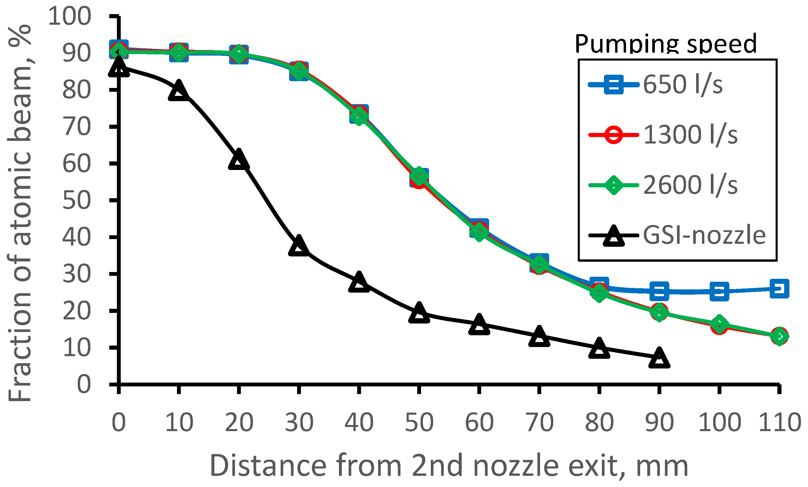
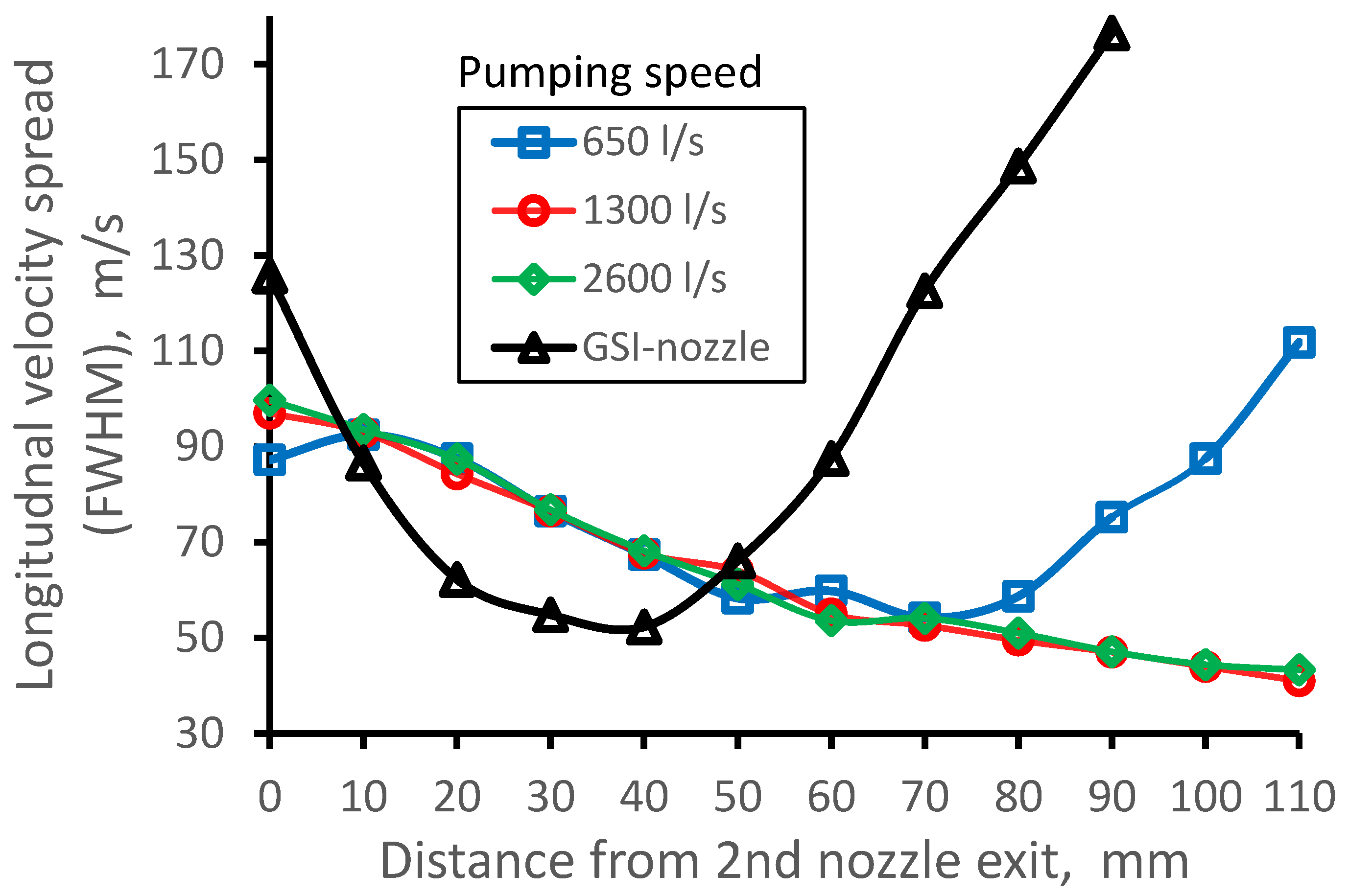
In addition to the previously considered variant of 1300 l/s pumping speed (it corresponds to Pbg = 2 × 10⁻² mbar), we have performed calculations for the pumping speed of 2600 l/s (Pbg = 1 × 10⁻² mbar) and 650 l/s (Pbg = 4 × 10⁻² mbar). The results of these calculations are presented in following Figure 20, Figure 21 and Figure 22. To provide a simple and direct comparison of the double-nozzle technique with the case of the GSI nozzle, we have included the results of calculations for the GSI setup [32,33] presented above in Section 2.
3.5. Effect of the Input (Stagnation) Pressure in the 2nd Nozzle
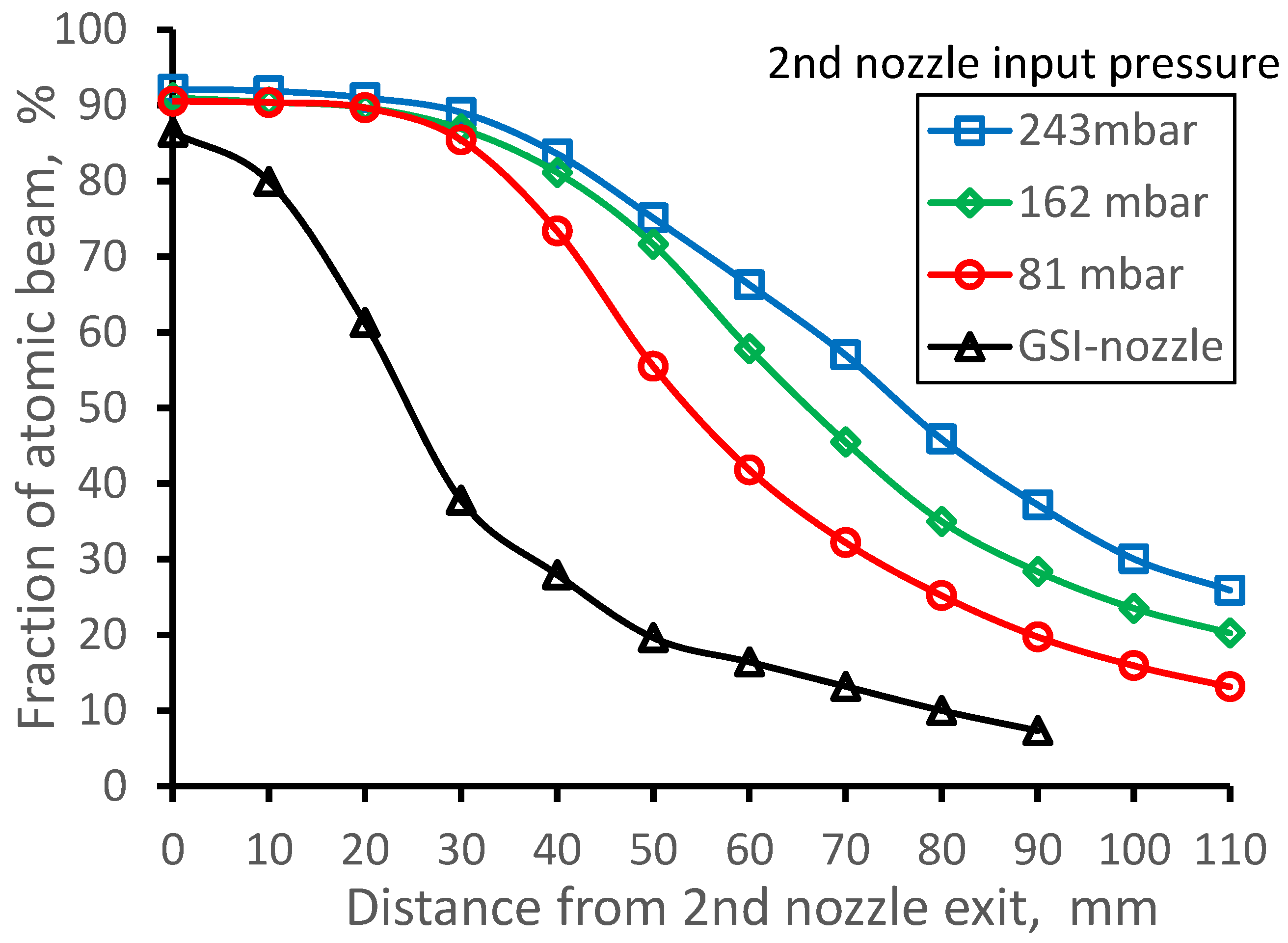
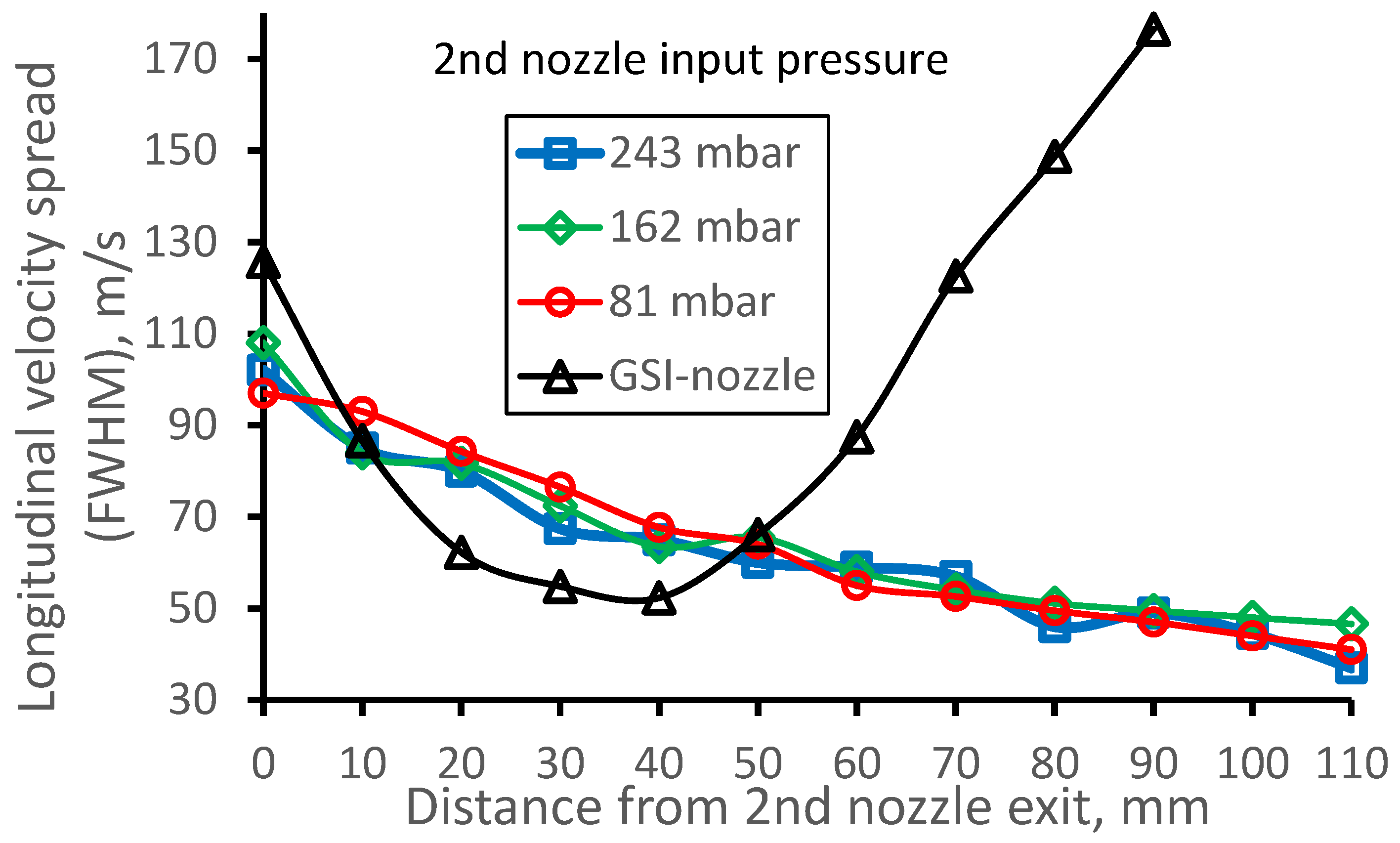
To make sure that the proposed here double-nozzle technique works effectively in a wide range of input pressures in the 2nd nozzle, we performed, in addition, gas dynamic and Monte Carlo simulations for two other pressures Pnoz and at fixed gas cell pressure Pcell = 100 mbar and pumping capacity of 1300 l/s. These variants are Pnoz = 162 mbar (the corresponding Pbg = 3 × 10⁻² mbar) and Pnoz = 263 mbar (the corresponding Pbg = 4 × 10⁻² mbar).
3.6. Effect of the Stagnation Pressure in the Gas Cell
To see how the double-nozzle technique will work at twice less stagnation pressure in the gas cell, we performed gas dynamic and Monte Carlo simulation for the case of Pcell = 50 mbar and input gas pressure Pnoz = 81 mbar. The pumping capacity of 1300 l/s corresponds to Pbg = 1.5 × 10⁻² mbar.
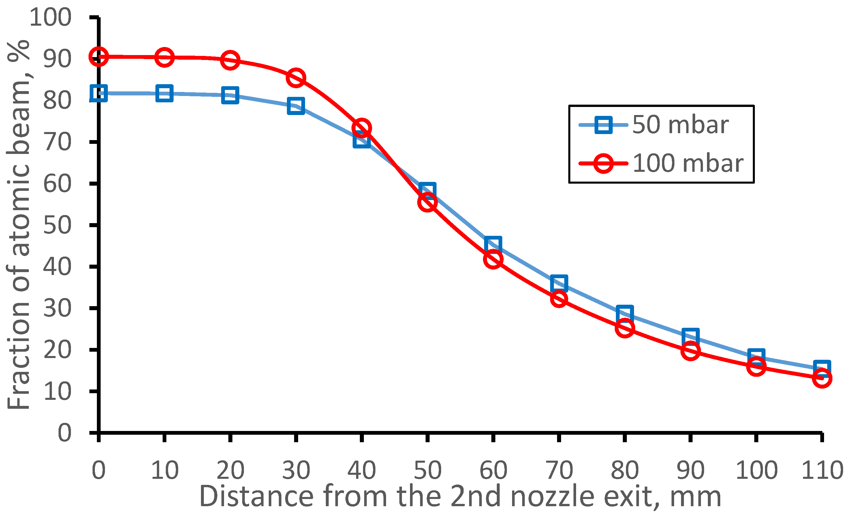
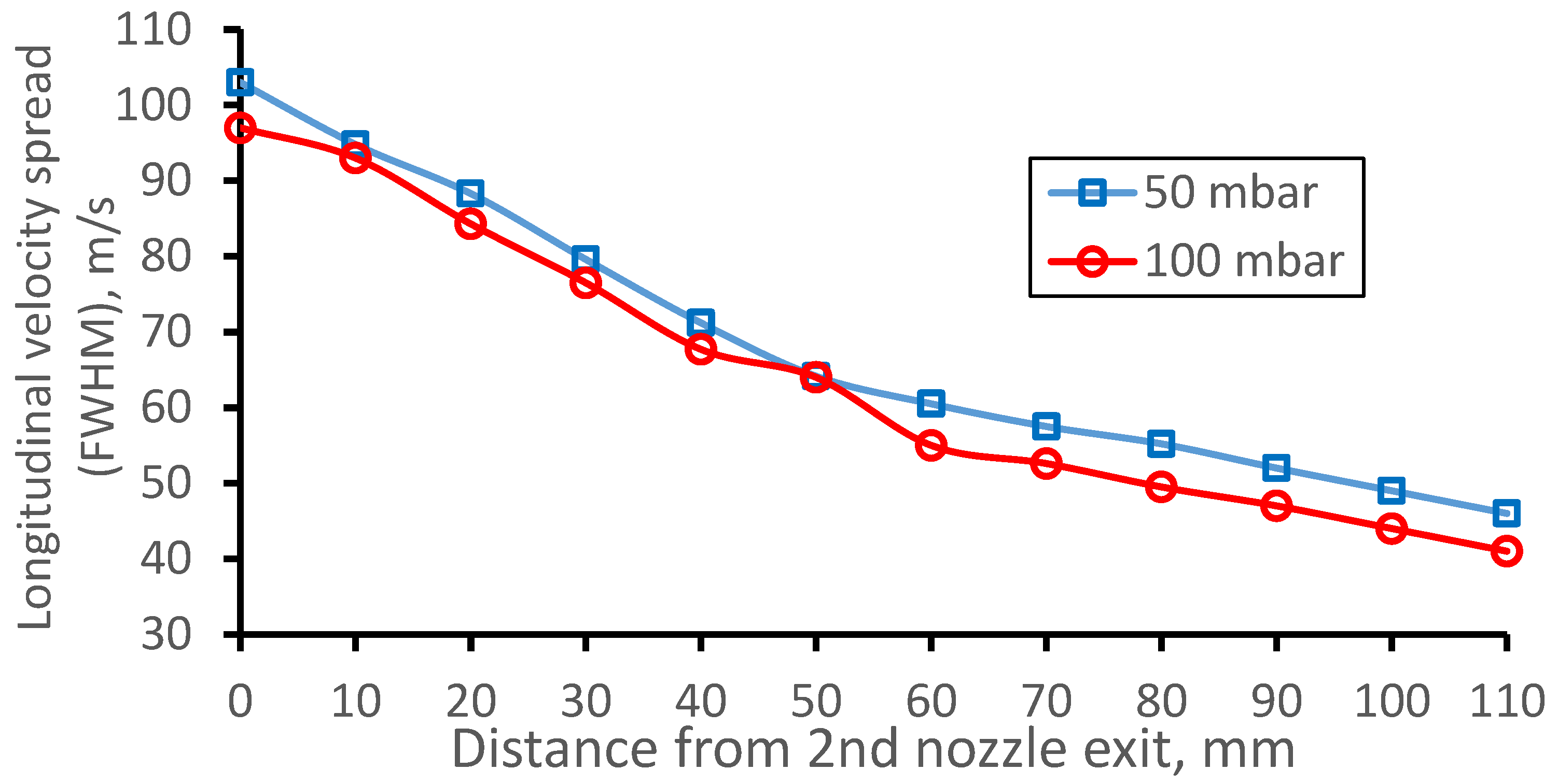
The Monte Carlo calculation results are presented in Figure 25 and Figure 26. The corresponding results for the previously considered case of stagnation Pcell = 100 mbar and Pbg = 2 × 10⁻² mbar we added for illustration and comparison.
Notice that the calculated diffusion losses of the atomic beam inside the double-nozzle device at Pcell = 50 mbar is 18.3 ± 0.6%, a factor of 2 higher than that for Pcell = 100 mbar, and it looks reasonable. Nevertheless, the data for two different Pcell values look very similar in Figure 25 and Figure 26. For comparison, it is not so for the GSI nozzle (see Figure 10 and Figure 11).
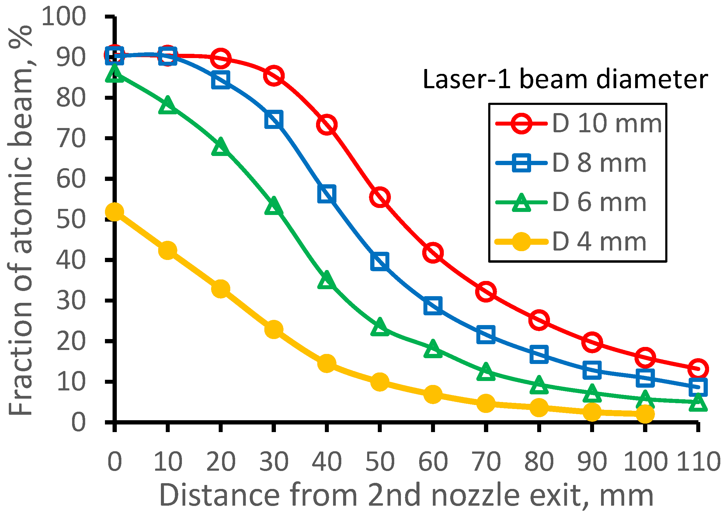
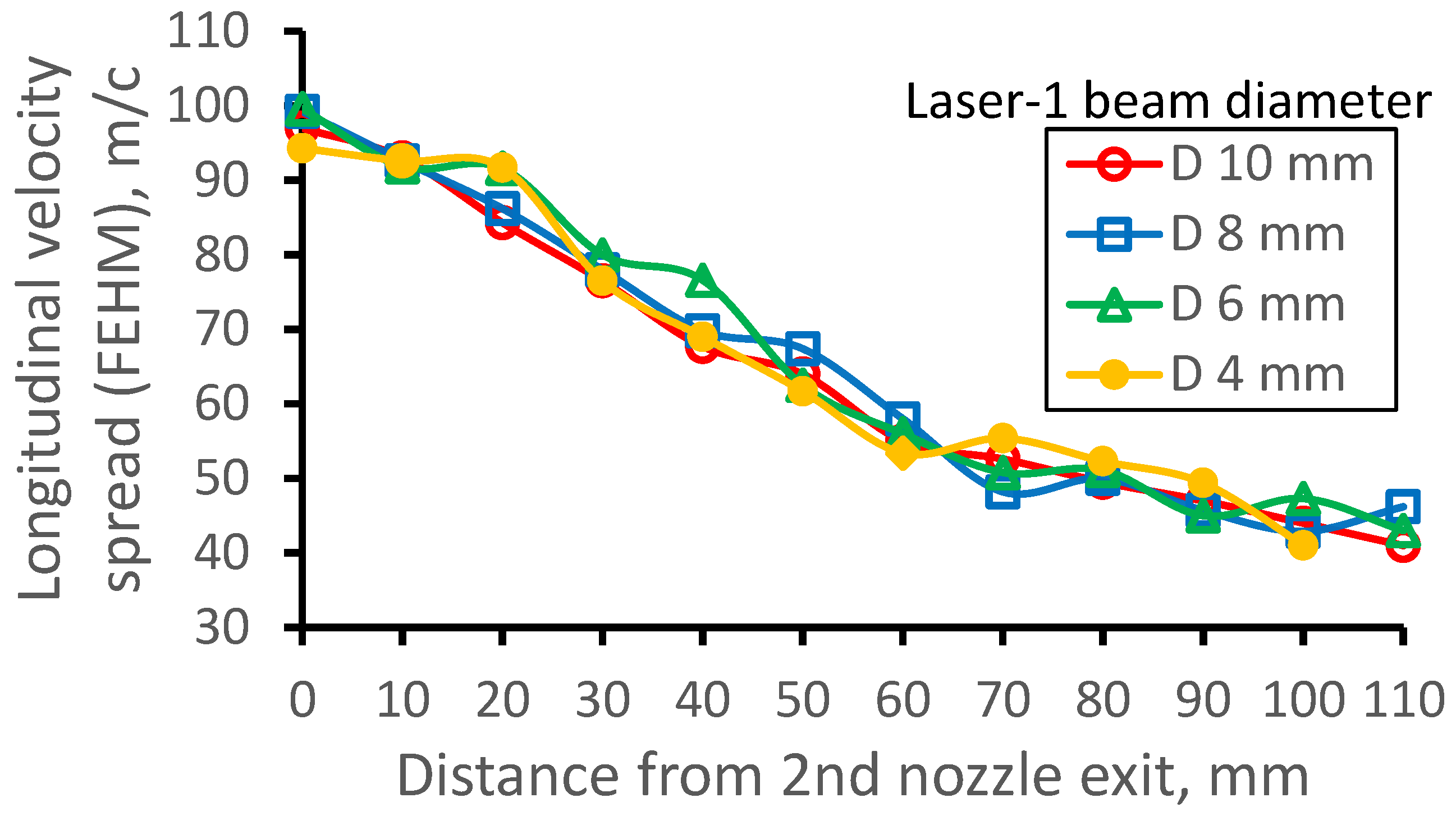
3.7. Effect of the Laser-1 Beam Diameter
When the distance between adjacent rods of the curved RFQ (the curved RFQ allows for the axial Laser-1 beam injection into the gas jet) is less than considered above the laser beam diameter of 10 mm, one should use the Laser-1 beam of a smaller diameter.
3.8. Monte Carlo Simulations for Nobelium Atoms in the Gas Jet
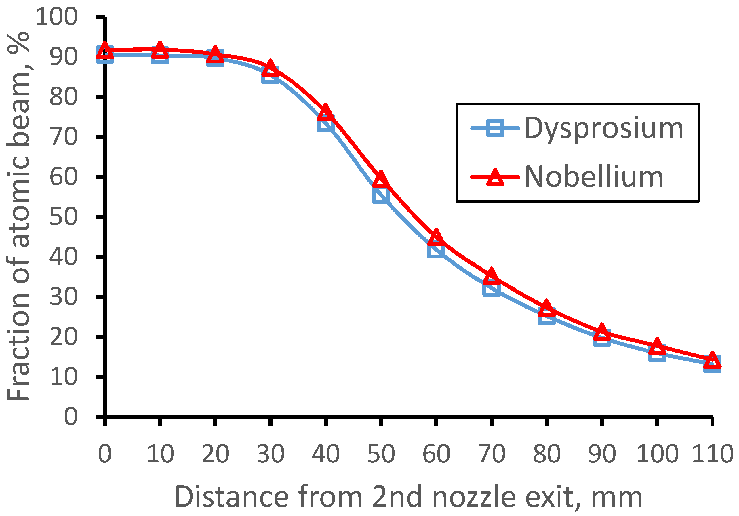
The goal of the JetRIS project [32,33] under development at GSI is the study of the nuclear properties of nobelium isotopes with high precision by laser spectroscopy in an argon supersonic gas jet. That is why we performed, in addition, a Monte Carlo simulation for 253No isotope, as well. For the Monte Carlo simulation of the nobelium atomic beam in a supersonic gas jet, we used the same results of gas dynamic simulation (see Figure 15) for the 164Dy atomic beam. These results are shown in Figure 29, Figure 30 and Figure 31. Results for the 164Dy we added for comparison.
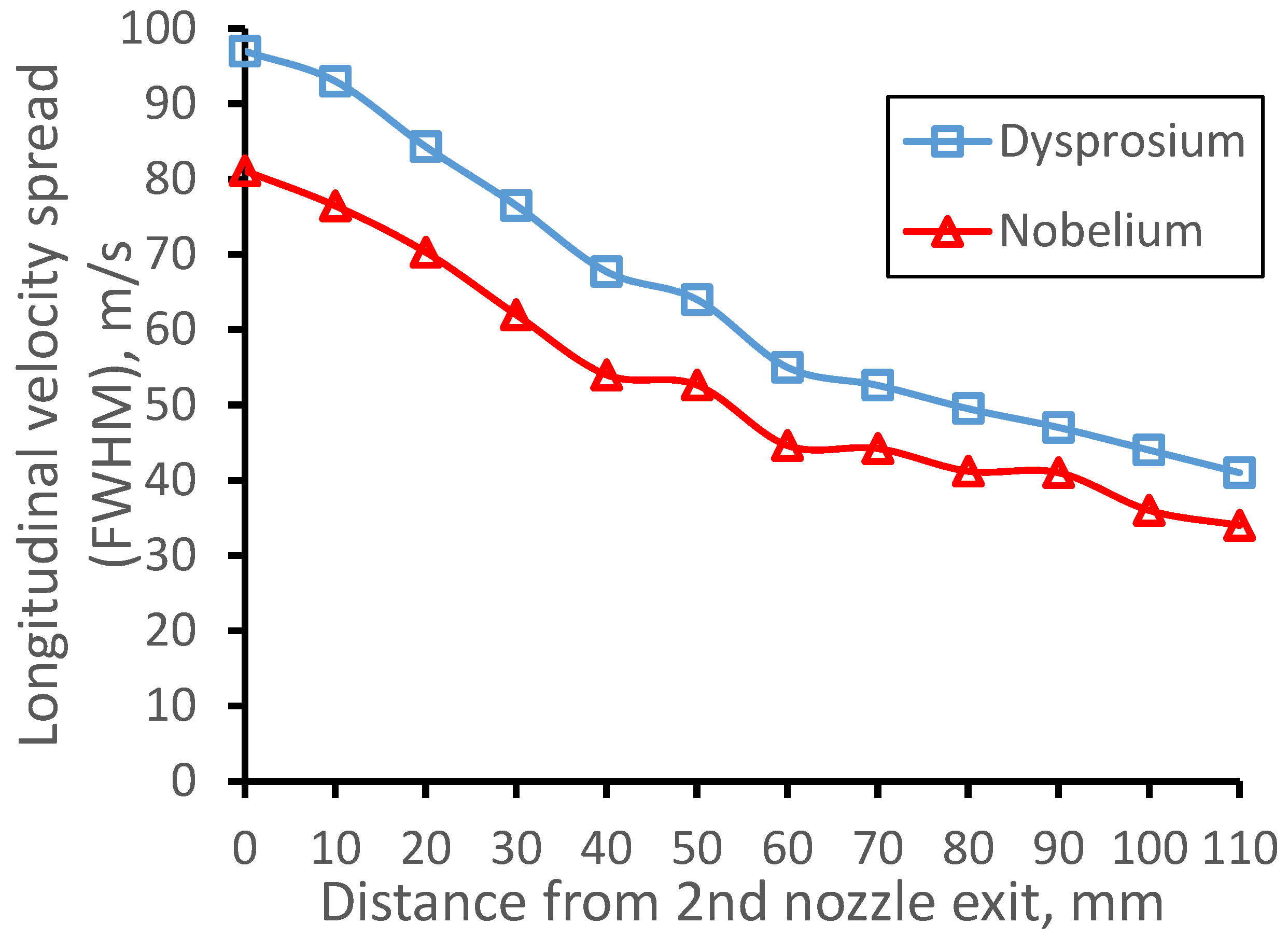
As shown in Figure 29, the decrease of the beam fractions with the distance from the 2nd nozzle exit is near the same for both dysprosium and nobelium atomic beams. It reflects that thermalized argon dysprosium and nobelium atoms equally follow the supersonic jet expansion. At the same time, the longitudinal velocity spreads shown in Figure 30 are different. It explains by the mass difference of 164Dy and 253No atoms because the velocity spread of the atomic beam thermalized in the gas should be inversely proportional to the square root of the atom mass.
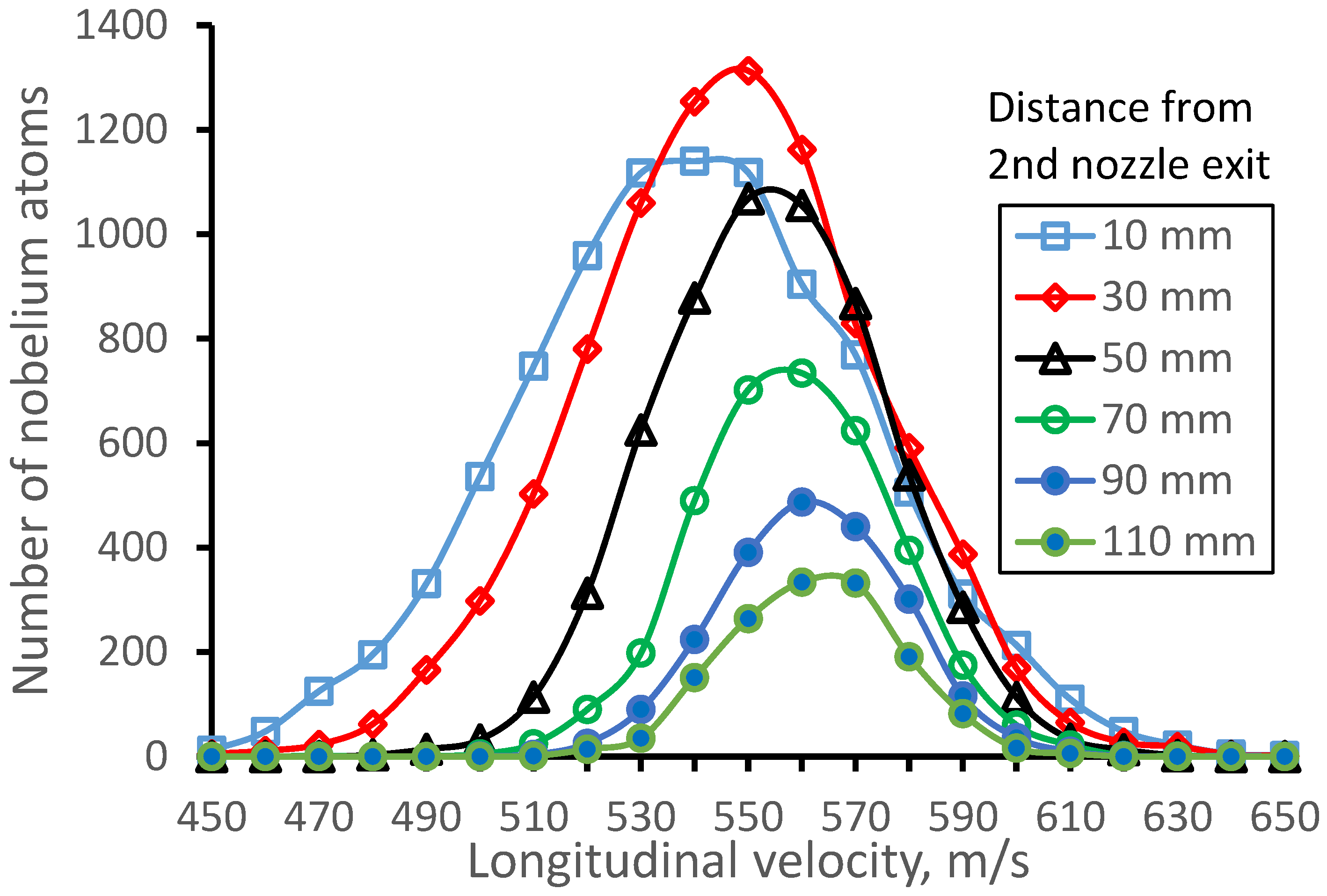
Figure 31 shows the 253No atomic beam longitudinal velocity distributions for different distances from the 2nd nozzle exit for illustration.
4. Discussion and Outlook
In Section 2 of the article, we have investigated by means of detailed computer experiments the conventional nowadays technique of the so-called in-gas-jet laser resonance ionization spectroscopy. As a typical representative of this technique, we have chosen for the numerical computer analysis the setup of the JetRIS project [32,33]. The JetRIS project is under development now at GSI, Darmstadt.
Results of the gas dynamic simulation for the exit flow channel of 12 mm in diameter are presented in Figure 1 and Figure 2. It is a laminar gas flow with a Reynolds number of 123. The calculated Monte Carlo simulation time-of-flight of evaporated 164Dy neutral atoms from the hot filament tip to the nozzle throat is 7.0 ± 1.4 ms (see Figure 3), the extraction efficiency is 94.5 ± 2.7%, or in other words, the atomic beam diffusion losses are equal to 5.5 ± 0.3%. The gas dynamic + Monte Carlo simulations show that the additional diffusion losses of the 164Dy atomic beam inside the GSI nozzle at Pcell = 100 mbar are equal to 15.6 ± 0.6%. The graphic description of the calculated argon supersonic jet (flow fields of gas density, velocity, temperature, and Mach number) flowing out of the GSI nozzle into the gas-jet chamber is shown in Figure 4 and Figure 9 for the gas cell pressure of 100 mbar and 50 mbar, correspondingly. Here the strong effect of the gas viscosity of the supersonic jet structure and parameters is visible.
Notice that the 164Dy atomic beam diffusion losses inside the GSI nozzle for Pcell = 50 mbar 27.7 ± 0.8% are considerably higher than that at Pcell = 100 mbar, which looks reasonable. Moreover, the production efficiency of excited by the Laser-1 dysprosium atoms in the gas jet is also less in the case of Pcell = 50 mbar (see Figure 10). As a result, the atomic beam quality, shown in Figure 11 as a longitudinal velocity spread, is also worse.
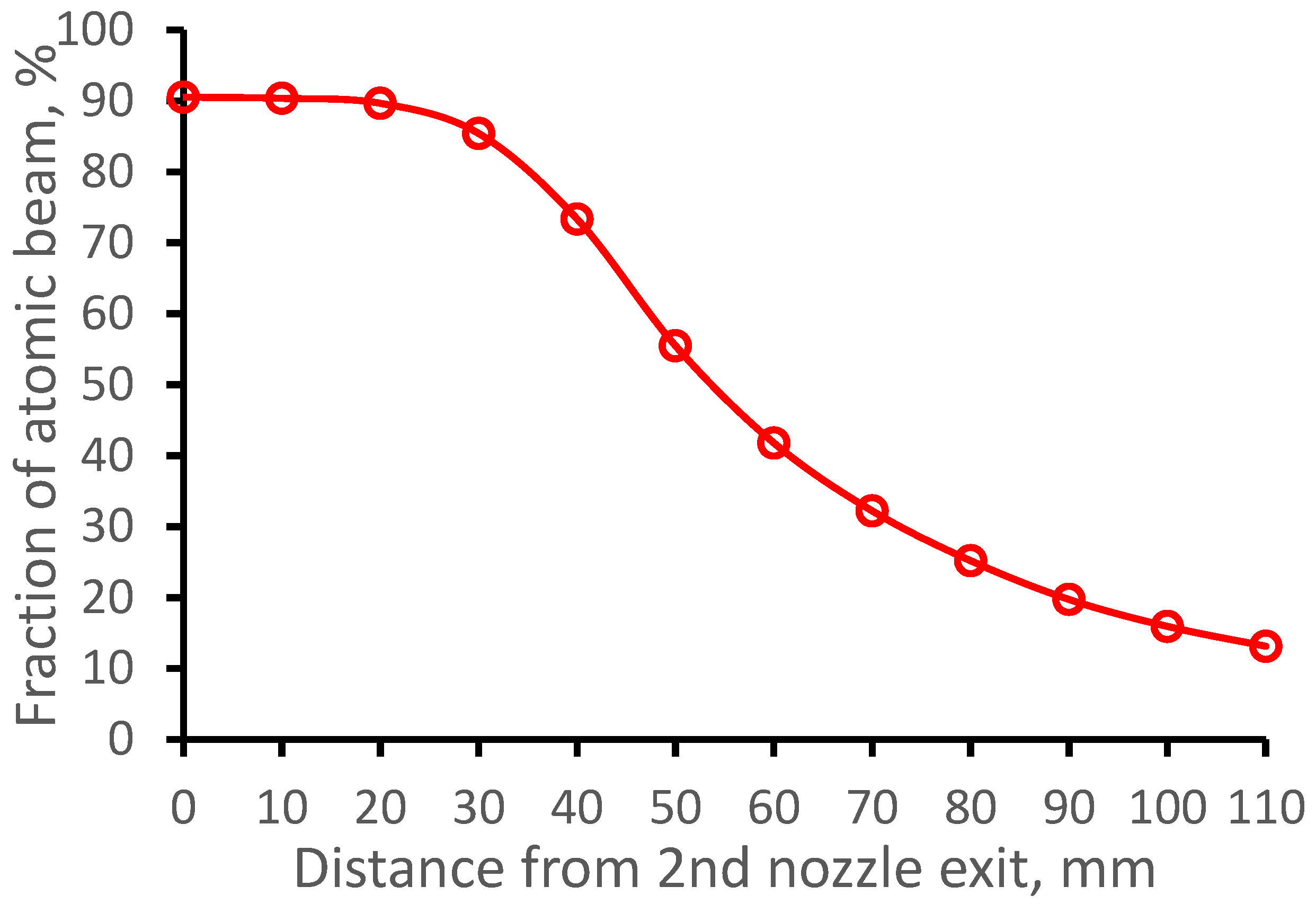
Section 3 of the article describes and explores our proposal for a new double-nozzle technique. By means of gas dynamics and Monte Carlo simulations, we have shown that this new technique has many advantages over the conventional technique described in Section 2 of the article. E.g., the atomic beam diffusion losses inside the double-nozzle system are equal only to 9.5 ± 0.4%, which is in factor 1.6 less than in the case of the use of GSI nozzle at the same gas cell pressure (Pcell = 100 mbar) and having the same nozzle throat diameter of 1.0 mm. The double nozzle method is much more efficient (see the direct comparison in Figure 16, Figure 21 and Figure 23), and it also allows obtaining better atomic beam quality (expressed in longitudinal velocity spread) for a longer downstream distance from the 2nd nozzle exit (see the direct comparison in Figure 17, Figure 22 and Figure 24).
The proposed double-nozzle technique can effectively work in various Pcell and Pnoz pressures. Therefore, there is no need here for the use of any butterfly valve placed in front of the vacuum pump, as it is in [32] to adjust the background pressure in the gas-jet chamber under changing the Pcell or using the nozzles having different throat diameters and profiles of its diverging supersonic part. The butterfly valve allows for decreasing the nominal capacity of the used vacuum pump, but it cannot increase it when required.
Moreover, the double-nozzle design we suggest in the JetRIS setup at GSI, whose main parameters are listed in Table 1, can be effectively used at different vacuum pump capacities (see Section 3.4 above).
To help the authors of works [32,33] prepare for the future online measurement of nobelium isotopes, we also performed the Monte Carlo simulations for the 253No atomic beam in the argon supersonic jet. The results of these calculations, which are presented in Section 3.7, allow us to quantitatively estimate the efficiency of the JetRIS setup operation using the proposed double-nozzle technique.
Implementing the proposed double-nozzle technique to the JetRIS setup will be enough to replace the present GSI nozzle with the double-nozzle system presented in the article.
In conclusion, we can say that the double-nozzle design, which main parameters are listed in Table 1, can also be used for other similar setups or/and projects. If, e.g., operation conditions or specific requirements to these setups/projects are very different from that in the JetRIS setup, then we can make similar computer experiments to find an optimal solution for these cases upon the corresponding request.
Funding
This research received no external funding.
Data Availability Statement
The data presented in this study are available upon request from the corresponding author.
Conflicts of Interest
The author declares no conflict of interest.
References
- Dendooven, P. The development and status of the IGISOL technique. Nucl. Instrum. Methods Phys. Res. B 1997, 126, 182–189. [Google Scholar] [CrossRef]
- Äystö, J. Development and applications of the IGISOL technique. Nucl. Instrum. Methods Phys. Res. A 2001, 693, 477–494. [Google Scholar] [CrossRef]
- Moore, I.D.; Dendooven, P.; Ärje, J. The IGISOL technique—Three decades of development. Hyperfine Interact 2014, 223, 17–62. [Google Scholar] [CrossRef]
- Schwarz, S.; Bollen, G.; Lawton, D.; Lofy, P.; Morrissey, D.J.; Ottarson, J.; Ringle, R.; Schury, P.; Sun, T.; Varentsov, V.; et al. The low-energy-beam and ion-trap facility at NSCL/MSU. Nucl. Instrum. Methods Phys. Res. B 2003, 204, 507–511. [Google Scholar] [CrossRef]
- Varentsov, V.L.; Habs, D. A cooler for intense low-energy ion beams. Nucl. Instrum. Methods Phys. Res. A 2003, 496, 286–292. [Google Scholar] [CrossRef]
- Varentsov, V.L.; Habs, D. Fair-wind gas cell—A new concept of a buffer gas cell design. Nucl. Instrum. Methods Phys. Res. A 2002, 490, 16–29. [Google Scholar] [CrossRef]
- Sonoda, T.; Fujita, M.; Yamazaki, A.; Endo, T.; Shinozuka, T.; Miyashita, Y.; Sato, N.; Goto, A.; Tanaka, E.; Suzuki; et al. Development of the RF-IGISOL at CYRIC. Nucl. Instrum. Methods Phys. Res. B 2007, 254, 295–299. [Google Scholar] [CrossRef]
- Moore, I.D. New concepts for the ion guide technique. Nucl. Instrum. Methods Phys. Res. B 2008, 266, 4434–4441. [Google Scholar] [CrossRef]
- Sonoda, T.; Wada, M.; Tomita, H.; Sakamoto, C.; Takatsuka, T.; Furukawa, T.; Iimura, H.; Ito, Y.; Kubo, T.; Matsuo, Y.; et al. Development of a resonant laser ionization gas cell for high-energy, short-lived nuclei. Nucl. Instrum. Methods Phys. Res. B 2013, 295, 1–10. [Google Scholar] [CrossRef]
- Schury, P.; Wada, M.; Ito, Y.; Arai, F.; Kaji, D.; Kimura, S.; Morimoto, K.; Haba, H.; Jeong, S.; Koura, H.; et al. Status of the low-energy super-heavy element facility at RIKEN. Nucl. Instrum. Methods Phys. Res. B 2016, 376, 425–428. [Google Scholar] [CrossRef]
- Cooper, K.; Sumithrarachchi, C.S.; Morrissey, D.J.; Levand, A.; Rodriguez, J.A.; Savard, G.; Schwarz, S.; Zabransky, B. Extraction of thermalized projectile fragments from a large volume gas cell. Nucl. Instrum. Methods Phys. Res. A 2014, 763, 543–546. [Google Scholar] [CrossRef]
- Schwarz, S.; Bollen, G.; Chouhan, S.; Das, J.J.; Green, M.; Magsig, C.; Morrissey, D.J.; Ottarson, J.; Sumithrarachchi, C.; Villari, A.C.C.; et al. The NSCL cyclotron gas stopper—Entering commissioning. Nucl. Instrum. Methods Phys. Res. B 2016, 376, 256–259. [Google Scholar] [CrossRef]
- Constantin, P.; Balabanski, D.L.; Anh, L.T.; Cuong, P.V.; May, B. Design of the gas cell for the IGISOL facility at ELI-NP. Nucl. Instrum. Methods Phys. Res. B 2017, 397, 1–10. [Google Scholar] [CrossRef]
- Savard, G.; Levand, A.F.; Zabransky, B.J. The CARIBU gas catcher. Nucl. Instrum. Methods Phys. Res. A 2012, 685, 70–77. [Google Scholar] [CrossRef]
- Saastamoinen, A.; Moore, I.D.; Ranjan, M.; Dendooven, P.; Penttilä, H.; Peräjärvi, K.; Popov, A.; Äystö, J. Characterization of a cryogenic ion guide at IGISOL. Nucl. Instrum. Methods Phys. Res. B 2016, 376, 246. [Google Scholar] [CrossRef]
- Ranjan, M.; Dendooven, P.; Purushothaman, S.; Dickel, T.; Reiter, M.P.; Ayet, S.; Haettner, E.; Moore, I.D.; Kalantar-Nayestanaki, N.; Geissel, H.; et al. Design, construction and cooling system performance of a prototype cryogenic stopping cell for the super-FRS at FAIR. Nucl. Instrum. Methods Phys. Res. A 2015, 770, 87–97. [Google Scholar] [CrossRef]
- Varentsov, V.; Yakushev, A. Concept of a new Universal High-Density Gas Stopping Cell Setup for study of gas-phase chemistry and nuclear properties of Super Heavy Elements (UniCell). Nucl. Instrum. Methods Phys. Res. A 2019, 940, 206–214. [Google Scholar] [CrossRef]
- Varentsov, V.L.; Wada, M. Computer experiments on ion beam cooling and guiding in fair-wind gas cell and extraction RF-funnel system. Nucl. Instrum. Methods Phys. Res. A 2004, 532, 210. [Google Scholar] [CrossRef]
- Varentsov, V.; Yakushev, A. Fair-wind gas cell for the UniCell setup. Nucl. Instrum. Methods Phys. Res. A 2021, 1010, 165487. [Google Scholar] [CrossRef]
- Boussaid, R.; Ban, G.; Quéméner, G.; Merrer, Y.; Lorry, J. Development of a radio-frequency quadrupole cooler for high beam currents. Phys. Rev. Accel. Beams 2017, 20, 124701. [Google Scholar] [CrossRef]
- Barquest, B.R.; Bollen, G.; Mantica, P.F.; Minamisono, K.; Ringle, R.; Schwarz, S. RFQ beam cooler and buncher for collinear laser spectroscopy of rare isotopes. Nucl. Instrum. Methods Phys. Res. A 2017, 866, 18–28. [Google Scholar] [CrossRef]
- Schwarz, S.; Bollen, G.; Ringle, R.; Savory, J.; Schury, P. The LEBIT ion cooler and buncher. Nucl. Instrum. Methods Phys. Res. A 2017, 816, 131–141. [Google Scholar] [CrossRef]
- Franberg, H.; Delahaye, P.; Billowes, J.; Blaum, K.; Catherall, R.; Duval, F.; Gianfrancesco, O.; Giles, T.; Jokinen, A.; Lindroos, M.; et al. Off-line commissioning of the ISOLDE cooler. Nucl. Instrum. Methods Phys. Res. A 2008, 266, 4502–4504. [Google Scholar] [CrossRef]
- Barquest, B.R.; Bale, J.C.; Dilling, J.; Gwinner, G.; Kanungo, R.; Krücke, R.; Pearson, M.R. Development of a new RFQ beam cooler and buncher for the CANREB project at TRIUMF. Nucl. Instrum. Methods Phys. Res. B 2016, 376, 207–210. [Google Scholar] [CrossRef]
- Brunner, T.; Smith, M.J.; Brodeur, M.; Ettenauer, S.; Gallant, A.T.; Simon, V.V.; Chaudhuri, A.; Lapierre, A.; Mane, E.; Ringle, R.; et al. TITAN’s digital RFQ ion beam cooler and buncher, operation and performance. Nucl. Instrum. Methods Phys. Res. A 2012, 676, 32–43. [Google Scholar] [CrossRef]
- Herfurth, F.; Dilling, J.; Kellerbauer, A.; Bollen, G.; Henry, S.; Kluge, H.-J.; Lamour, E.; Lunney, D.; Moore, R.B.; Scheidenberger, C.; et al. A linear radiofrequency ion trap for accumulation, bunching, and emittance improvement of radioactive ion beams. Nucl. Instrum. Methods Phys. Res. A 2001, 469, 254–275. [Google Scholar] [CrossRef]
- Varentsov, V. Review of Gas Dynamic RF-Only Funnel Technique for Ion Beams Cooling and Extraction into Vacuum; FAIR: Darmstadt, Germany, 2022. [Google Scholar] [CrossRef]
- Yanga, X.F.; Wang, S.J.; Wilkins, S.G.; Ruiz, R.F.G. Laser Spectroscopy for the Study of Exotic Nuclei. Prog. Part. Nucl. Phys. 2023, 129, 104005. [Google Scholar] [CrossRef]
- Block, M.; Giacoppo, F.; Heßberger, F.-P.; Raeder, S. Recent progress in experiments on the heaviest nuclides at SHIP. Riv. Nuovo Cim. 2022, 45, 279–323. [Google Scholar] [CrossRef]
- Van Duppen, P. In-Gas Jet Laser Ionization Spectroscopy of Heavy Elements. Available online: https://www.psi.ch/sites/default/files/import/ltp/ThursdayColloquiaEN/2018_11_Laser_spectroscopy_Heavy_Elements_Piet_Van_Duppen.pdf (accessed on 23 May 2023).
- Kudryavtsev, Y.; Ferrer, R.; Huyse, M.; Van den Bergh, P.; Van Duppen, P. The in-gas-jet laser ion source: Resonance ionization spectroscopy of radioactive atoms in supersonic gas jets. Nucl. Instrum. Methods Phys. Res. B 2013, 297, 7–22. [Google Scholar] [CrossRef]
- Raeder, S.; Block, M.; Chhetri, P.; Ferrer, R.; Kraemer, S.; Kron, T.; Laatiaoui, M.; Nothhelfer, S.; Schneider, F.; Van Duppen, P.; et al. A gas-jet apparatus for high-resolution laser spectroscopy on the heaviest elements at SHIP. Nucl. Instrum. Methods Phys. Res. B 2020, 463, 272–276. [Google Scholar] [CrossRef]
- Münzberg, D.; Block, M.; Claessens, A.; Ferrer, R.; Laatiaoui, M.; Lantis, J.; Nothhelfer, S.; Raeder, S.; Van Duppen, P. Resolution Characterizations of JetRIS in Mainz Using 164Dy. Atoms 2022, 10, 57. [Google Scholar] [CrossRef]
- Ferrer, R.; Barzakh, A.; Bastin, B.; Beerwerth, R.; Block, M.; Creemers, P.; Grawe, H.; de Groote, R.; Delahaye, P.; Fle, X.; et al. Towards high-resolution laser ionization spectroscopy of the heaviest elements in supersonic gas jet expansion. Nat. Commun. 2017, 8, 14520. [Google Scholar] [CrossRef] [PubMed]
- Ferrer, R.; Verlinde, M.; Verstraelen, E.; Claessens, A.; Huyse, M.; Kraemer, S.; Kudryavtsev, Y.; Romans, J.; Van den Bergh, P.; Van Duppen, P.; et al. Hypersonic nozzle for laser-spectroscopy studies at 17 K characterized by resonance-ionization-spectroscopy-based flow mapping. Phys. Rev. Res. 2021, 3, 043041. [Google Scholar] [CrossRef]
- Sels, S.; Ferrer, R.; Dockx, K.; Buitrago, C.G.; Huyse, M.; Kudryavtsev, Y.; Kraemer, S.; Raedera, S.; Van Den Bergh, P.; Van Duppen, P.; et al. Design and commissioning of an ion guide system for In-Gas Laser Ionization and Spectroscopy experiments. Nucl. Instrum. Methods Phys. Res. B 2020, 463, 148–153. [Google Scholar] [CrossRef]
- Romans, J.; Ajayakumar, A.; Authier, M.; Boumard, F.; Caceres, L.; Cam, J.-F.; Claessens, A.; Damoy, S.; Delahaye, P.; Desrues, P.; et al. First Offline Results from the S3 Low-Energy Branch. Atoms 2022, 10, 21. [Google Scholar] [CrossRef]
- Hirayama, Y.; Watanabe, Y.X.; Schury, P.; Mukai, M.; Choi, H.; Ahmed, M.; Kakiguchi, Y.; Oyaizu, M.; Wada, M.; Miyatake, H. In-gas-jet laser ionization spectroscopy at KISS. RIKEN Accel. Prog. Rep. 2019, 52, 1. [Google Scholar]
- Varentsov, V.L.; Ignatiev, A.A. Numerical investigations of internal supersonic jet targets formation for storage rings. Nucl. Instrum. Methods Phys. Res. A 1998, 413, 447–456. [Google Scholar] [CrossRef]
- Varentsov, V.L. Focused ion beam source of a new type for micro- and nanoelectronic technologies. In Micro- and Nanoelectronics; SPIE: Philadelphia, PA, USA, 2008; Volume 7025, pp. 702509–702521. [Google Scholar] [CrossRef]
- Varentsov, V. Proposal of an RF-Only Double-Funnel System for Ions Extraction from a Cryogenic Stopping Cell for the Super-FRS at FAIR. GSI Sci. Rep. 2015, 1, 503–504. [Google Scholar] [CrossRef]
- Varentsov, V. Proposal of a new Laser ablation ion source for LaSpec and MATS testing. In Proceedings of the NUSTAR Collaboration Meeting, Darmstadt, Germany, 29 February–4 March 2016. [Google Scholar] [CrossRef]
- Brunner, T.; Fudenberg, D.; Varentsov, V.; Sabourov, A.; Gratta, G.; Dilling, J.; nEXO Collaboration. An RF-only ion-funnel for extraction from high-pressure gases. Int. J. Mass Spectrom. 2015, 379, 110–120. [Google Scholar] [CrossRef]
- Ratajczyk, T.; Bollinger, P.; Lellinger, T.; Varentsov, V.; Nörtershäuser, W. Towards a He-buffered laser ablation ion source for collinear laser spectroscopy. Hyperfine Interact 2020, 241, 52. [Google Scholar] [CrossRef]
- Valverde, A.A.; Brodeur, M.; Burdette, D.P.; Clark, J.A.; Klimes, J.W.; Lascar, D.; O’Malley, P.D.; Ringle, R.; Savard, G.; Varentsov, V. Stopped, bunched beams for the twinsol facility. Hyperfine Interact 2019, 240, 38. [Google Scholar] [CrossRef]
- O’Malley, P.D.; Brodeur, M.; Burdette, D.P.; Klimes, J.W.; Valverde, A.; Clark, J.A.; Savard, G.; Ringle, R.; Varentsov, V. Testing the weak interaction using St. Benedict at the University of Notre Dame. Nucl. Instrum. Methods Phys. Res. B 2020, 463, 488–490. [Google Scholar] [CrossRef]
- Murray, K.; Dilling, J.; Gornea, R.; Ito, Y.; Koffas, T.; Kwiatkowski, A.A.; Lan, Y.; Reiter, M.P.; Varentsov, V.; Brunner, T. With the nEXO collaboration. Design of a Multiple-Reflection time-of-flight Mass-Spectrometer for Barium-tagging. Hyperfine Interact 2019, 240, 97. [Google Scholar] [CrossRef]
- Querci, L.; Varentsov, V.; Günther, D.; Hattendorf, B. An RF-only ion funnel interface for ion cooling in laser ablation time of flight mass spectrometry. Spectrochim. Acta B 2018, 146, 57–68. [Google Scholar] [CrossRef]
- Tiedemann, D.; Stiebing, K.E.; Winters, D.F.A.; Quint, W.; Varentsov, V.; Warczak, A.; Malarz, A.; Stöhlker, T. A pulsed supersonic gas jet target for precision spectroscopy at the HITRAP facility at GSI. Nucl. Instrum. Methods Phys. Res. A 2014, 764, 387–393. [Google Scholar] [CrossRef]
- Varentsov, V.L.; Kuroda, N.; Nagata, Y.; Torii, H.A.; Shibata, M.; Yamazaki, Y. ASACUSA Gas-Jet Target: Present Status and Future Development. AIP Conf. Proc. 2005, 793, 328–340. [Google Scholar] [CrossRef]
- Yakushev, A.; Wey, Y.; Simonovski, D.; Düllmann, C.E.; Vrentsov, V. Towards chemistry beyond moscovium (Mc, Z = 115). In Proceedings of the TASCA Collaboration Meeting, Rennes, France, 9–11 May 2022. [Google Scholar] [CrossRef]
- Varentsov, V.L.; Yaschuk, V.V. Technique of Phase Volume Decrease of an Atomic Beam. Inventor’s Certificate (USSR) Patent No. 774523, 14 May 1979. [Google Scholar]
- Varentsov, V.L.; Yashchuk, V.V. Gasdynamic method for reducing the phase volume of an atomic beam. Sov. Tech. Phys. Lett. 1983, 9, 65–66. [Google Scholar]
- Varentsov, V.L. The Method of an Atomic Beam Phase Volume Decrease and Its Possible Application for Atomic and Nuclear Physics Problems. Ph.D. Thesis, Leningrad Nuclear Physics Institute, Gatchina, Russia, 1986; pp. 1–140. (In Russian). [Google Scholar]
- Varentsov, V.L. Gas dynamic cooling of low-energy molecular and ion beams. J. Technol. Phys. 1994, 39, 358–363. [Google Scholar]
- Varentsov, V.L.; Ezhov, V.F.; Kniaz’kov, V.A.; Ryabov, V.L.; Khazov, A.Y.; Yaschuk, V.V. Time-of-flight molecular-beam spectrometer. Prib. Tekh. Eksp. 1986, 1, 152–154. [Google Scholar]
- Varentsov, V.L.; Ezhov, V.F.; Kniaz, V.A.; Muratov, V.G.; Ryabov, V.L.; Khazov, A.Y.; Yaschuk, V.V. High-intensity gas dynamic molecular beam source of a new type. J. Tech. Phys. 1987, 57, 755. [Google Scholar]
- Varentsov, V.L.; Hansevarov, D.R. A new approach to the nozzle design of gas-jet targets. Nucl. Instrum. Methods Phys. Res. A 1992, 317, 1–6. [Google Scholar] [CrossRef]
- Varentsov, V.L.; Hansevarov, D.R.; Varentsov, D.V. The generation of an internal molecular-beam target from expensive gaseous and nonvolatile substances for storage rings. Nucl. Instrum. Methods Phys. Res. A 1995, 352, 542–547. [Google Scholar] [CrossRef]
- Varentsov, V. Windowless gas dynamic ion beam cooler and buncher. Nucl. Instrum. Methods Phys. Res. A 2020, 984, 164596. [Google Scholar] [CrossRef]
- Varentsov, V. Gas Dynamic Cooling of Low Energy Molecular and Ion Beams; Stefan Meyer Institute (SMI)): Vienna, Austria, 2004. [Google Scholar] [CrossRef]
Figure 1.
Results of the gas dynamic simulation for the argon velocity flow field inside the exit flow channel. The stagnation pressure Pcell = 100 mbar, and the temperature of the channel walls Tcell = 296 K. The arrowed black lines show the gas flow direction.
Figure 1.
Results of the gas dynamic simulation for the argon velocity flow field inside the exit flow channel. The stagnation pressure Pcell = 100 mbar, and the temperature of the channel walls Tcell = 296 K. The arrowed black lines show the gas flow direction.

Figure 2.
The calculated radial gas velocity profile is in the middle of the exit flow channel.

Figure 3.
The time-of-flight of 164Dy atoms from the filament tip to the nozzle throat. Total number of calculated atoms is 5000.
Figure 3.
The time-of-flight of 164Dy atoms from the filament tip to the nozzle throat. Total number of calculated atoms is 5000.

Figure 4.
Results of the gas dynamic simulation for GSI nozzle: (a) density, (b) temperature, (c) velocity and (d) Mach number flow fields. The stagnation pressure and temperature in the gas cell are Pcell = 100 mbar and Tcell = 296 K, correspondingly. Background pressure in the vacuum gas-jet chamber is Pbg = 6.47 × 10⁻³ mbar. Black arrowed lines show the gas flow directions.

Figure 5.
Results of the Monte-Carlo trajectory simulations of the fraction extracted from the gas cell 164Dy atomic beam inside the region of 10 mm (the Laser-1 beam diameter) as a function of distance from GSI nozzle exit. The number of calculated atoms is 10,000.
Figure 5.
Results of the Monte-Carlo trajectory simulations of the fraction extracted from the gas cell 164Dy atomic beam inside the region of 10 mm (the Laser-1 beam diameter) as a function of distance from GSI nozzle exit. The number of calculated atoms is 10,000.

Figure 6.
Results of the Monte-Carlo trajectory simulations for 164Dy atomic beam longitudinal velocity spread (FWHM) as a function of the distance from GSI nozzle exit. The data averaged in the radial plane for the Laser-1 beam diameter of 10 mm. Number of calculated atoms is 10,000.
Figure 6.
Results of the Monte-Carlo trajectory simulations for 164Dy atomic beam longitudinal velocity spread (FWHM) as a function of the distance from GSI nozzle exit. The data averaged in the radial plane for the Laser-1 beam diameter of 10 mm. Number of calculated atoms is 10,000.

Figure 7.
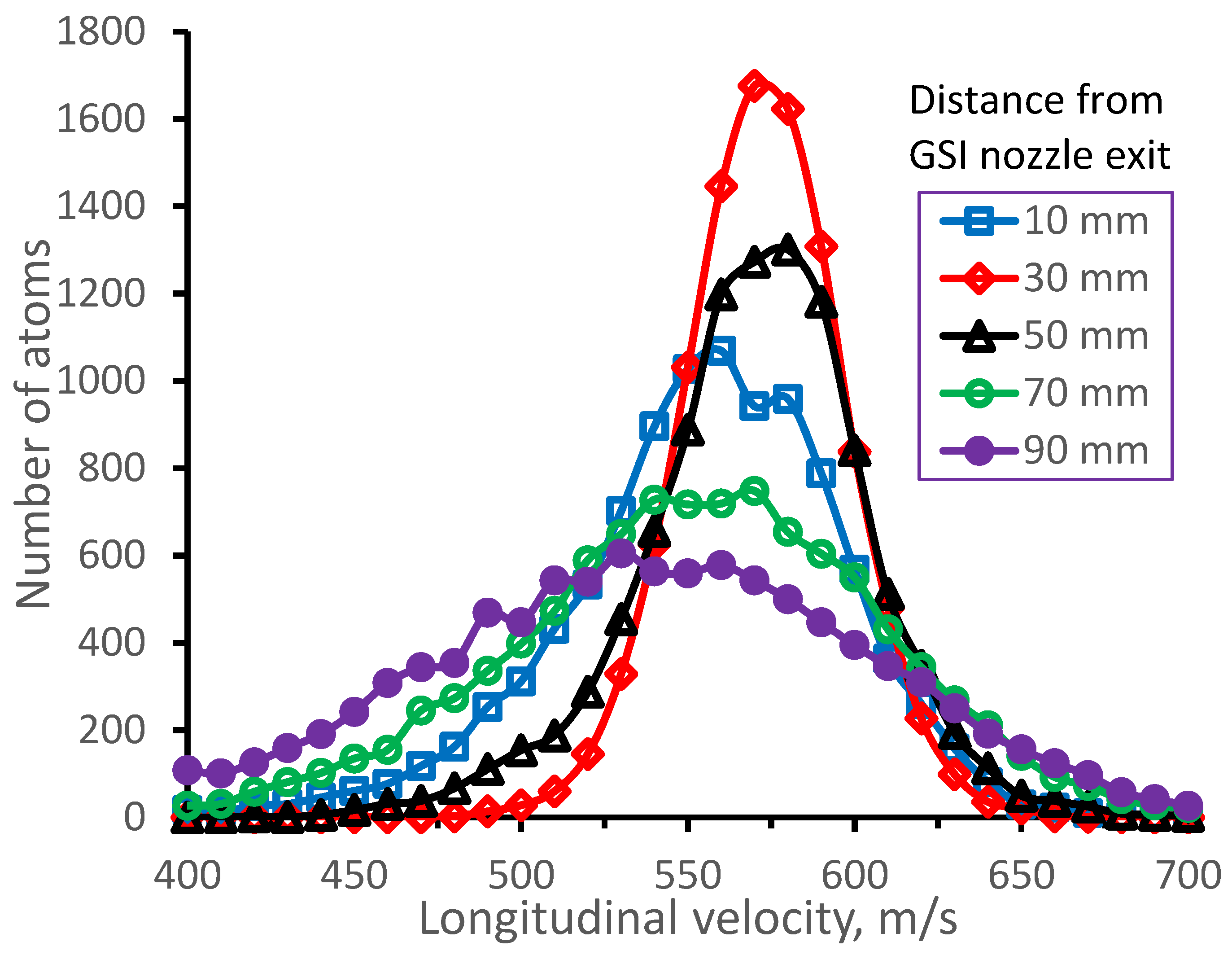
Results of the Monte-Carlo trajectory simulations for 164Dy atomic beam longitudinal velocity distributions (averaged in the radial plane for the Laser-1 beam diameter of 10 mm) for different distances from GSI nozzle exit. The number of calculated atoms for each velocity distribution is 10,000.
Figure 7.
Results of the Monte-Carlo trajectory simulations for 164Dy atomic beam longitudinal velocity distributions (averaged in the radial plane for the Laser-1 beam diameter of 10 mm) for different distances from GSI nozzle exit. The number of calculated atoms for each velocity distribution is 10,000.

Figure 8.
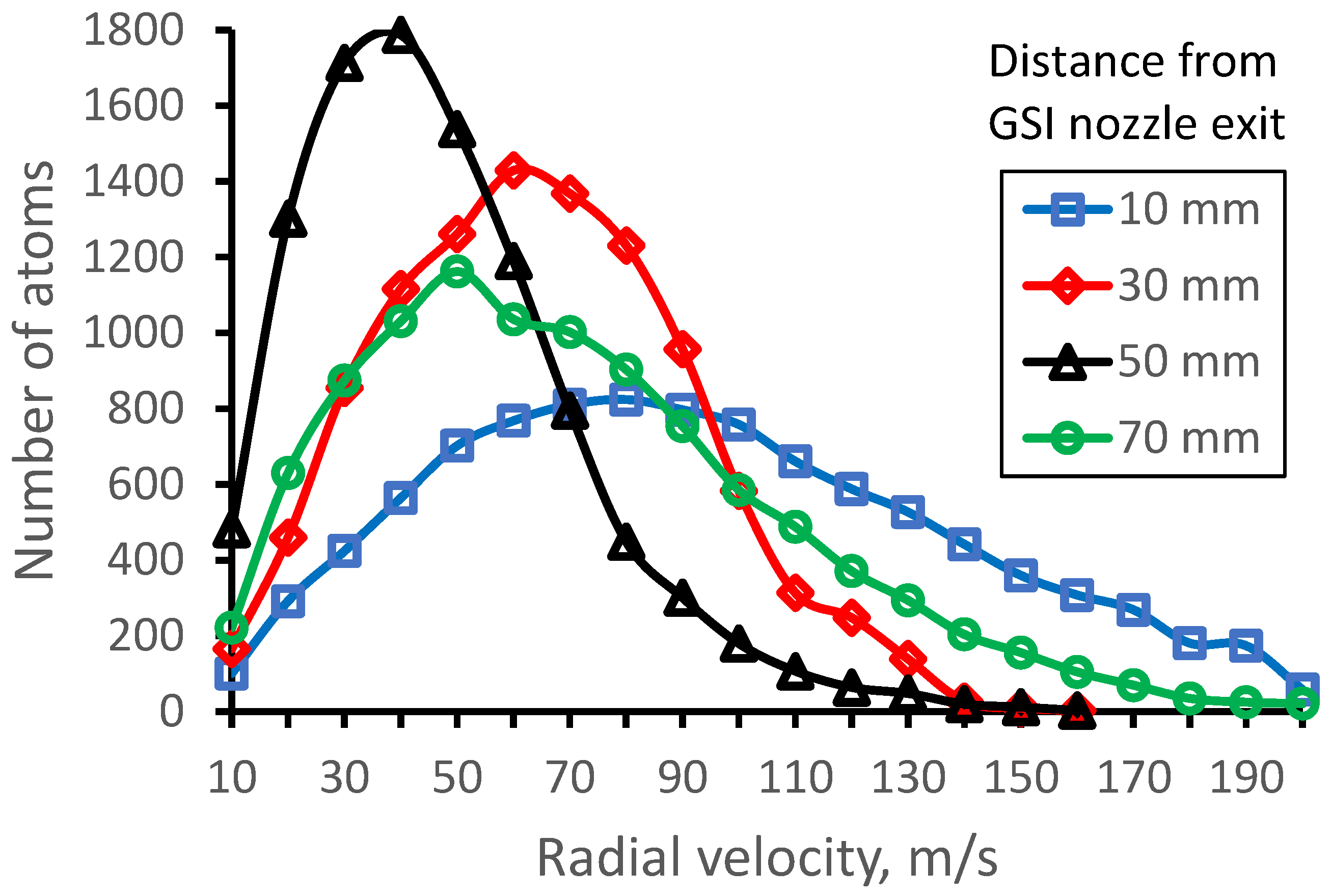
Results of the Monte-Carlo trajectory simulations for 164Dy atomic beam radial velocity distributions (averaged in the radial plane for the Laser-1 beam diameter of 10 mm) for different distances from GSI nozzle exit. The number of calculated atoms for each velocity distribution is 10,000.
Figure 8.
Results of the Monte-Carlo trajectory simulations for 164Dy atomic beam radial velocity distributions (averaged in the radial plane for the Laser-1 beam diameter of 10 mm) for different distances from GSI nozzle exit. The number of calculated atoms for each velocity distribution is 10,000.

Figure 9.
Results of the gas dynamic simulation: (a) density, (b) temperature, (c) velocity and (d) Mach number flow fields for GSI nozzle. The stagnation pressure and temperature in the gas cell are Pcell = 50 mbar and Tcell = 296 K, correspondingly. Background pressure in the gas-jet chamber is Pbg = 3.23 × 10⁻³ mbar. Black arrowed lines show the gas flow directions.

Figure 10.
Results of the Monte-Carlo trajectory simulations of the fraction extracted from the gas cell 164Dy atomic beam inside the region of 10 mm in diameter (it is the Laser-1 diameter) as a function of distance from GSI nozzle exit. Number of calculated atoms is 10,000.
Figure 10.
Results of the Monte-Carlo trajectory simulations of the fraction extracted from the gas cell 164Dy atomic beam inside the region of 10 mm in diameter (it is the Laser-1 diameter) as a function of distance from GSI nozzle exit. Number of calculated atoms is 10,000.

Figure 11.
Results of the Monte-Carlo trajectory simulations for 164Dy atomic beam longitudinal velocity spread (FWHM) as a function of distance from GSI nozzle exit. The data averaged in the radial plane for the Laser-1 beam diameter of 10 mm. Number of calculated atoms is 10,000.
Figure 11.
Results of the Monte-Carlo trajectory simulations for 164Dy atomic beam longitudinal velocity spread (FWHM) as a function of distance from GSI nozzle exit. The data averaged in the radial plane for the Laser-1 beam diameter of 10 mm. Number of calculated atoms is 10,000.

Figure 12.
Schematic of the method of gas dynamic cooling of low-energy molecular and ion beams. Picture from Refs. [39,61]. See the text for details.

Figure 13.
Schematic view of the double-nozzle design combined with the gas dynamic simulation results for argon temperature flow field. The stagnation gas cell pressure Pcell = 100 mbar, gas input (stagnation) pressure Pnoz = 81 mbar, background presses in the vacuum gas-jet chamber Pbg = 2.0 × 10⁻² mbar for the pumping capacity of 1300 l/s. The temperature of the gas cell and nozzles is 296 K. Black arrowed lines show the gas flow directions. Two black dashed vertical lines designate a possible connection of flanges for assembling this double-nozzle device.

Figure 14.
A schematic view of the double-nozzle design is shown in Figure 13 but combined with the results of the gas dynamic simulation for the argon velocity flow field.
Figure 14.
A schematic view of the double-nozzle design is shown in Figure 13 but combined with the results of the gas dynamic simulation for the argon velocity flow field.

Figure 15.
Results of the gas dynamic simulation: (a) density, (b) temperature (c) velocity and (d) Mach number flow fields for the double-nozzle. The stagnation gas cell pressure Pcell = 100 mbar, gas input (stagnation) pressure Pnoz = 81 mbar, background pressure in the vacuum gas-jet chamber Pbg = 2.0 × 10⁻² mbar for the pumping capacity of 1300 l/s. The temperature of the gas cell and both nozzles is 296 K. Black arrowed lines show the gas flow direction.

Figure 16.
Results of the Monte-Carlo trajectory simulations of the fraction extracted from the gas cell 164Dy atomic beam inside the gas jet of 10 mm diameter (Laser-1 diameter) as a function of distance from the 2nd nozzle exit. Number of calculated atoms is 10,000.
Figure 16.
Results of the Monte-Carlo trajectory simulations of the fraction extracted from the gas cell 164Dy atomic beam inside the gas jet of 10 mm diameter (Laser-1 diameter) as a function of distance from the 2nd nozzle exit. Number of calculated atoms is 10,000.

Figure 17.
Results of the Monte-Carlo trajectory simulations for 164Dy atomic beam longitudinal velocity spread (FWHM) as a function of the distance from the 2nd nozzle exit. The data averaged in the radial plane for the Laser-1 beam diameter of 10 mm. Number of calculated atoms is 10,000.
Figure 17.
Results of the Monte-Carlo trajectory simulations for 164Dy atomic beam longitudinal velocity spread (FWHM) as a function of the distance from the 2nd nozzle exit. The data averaged in the radial plane for the Laser-1 beam diameter of 10 mm. Number of calculated atoms is 10,000.

Figure 18.
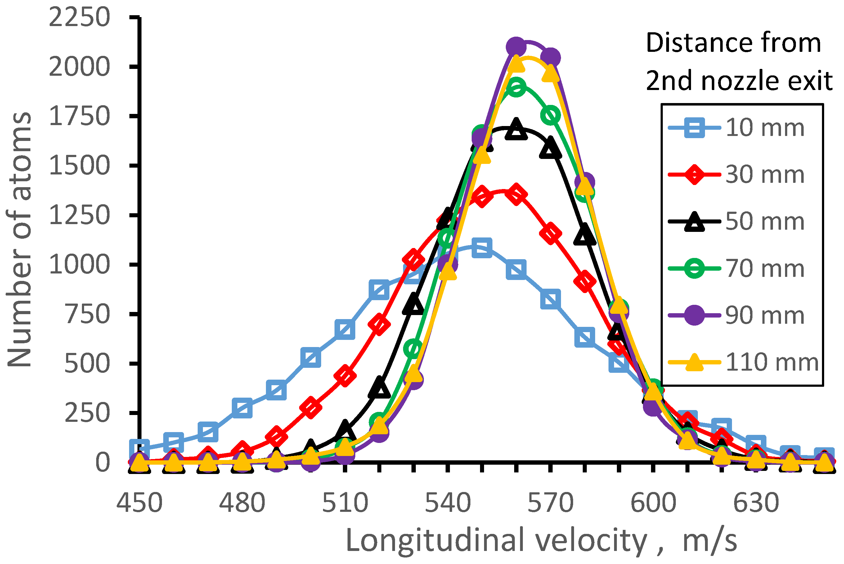
Results of the Monte-Carlo trajectory simulations for 164Dy atomic beam longitudinal velocity distributions (averaged in the radial plane for the Laser-1 beam diameter of 10 mm) for different distances from the 2nd nozzle exit. The number of calculated atoms for each velocity distribution is 10,000.
Figure 18.
Results of the Monte-Carlo trajectory simulations for 164Dy atomic beam longitudinal velocity distributions (averaged in the radial plane for the Laser-1 beam diameter of 10 mm) for different distances from the 2nd nozzle exit. The number of calculated atoms for each velocity distribution is 10,000.

Figure 19.
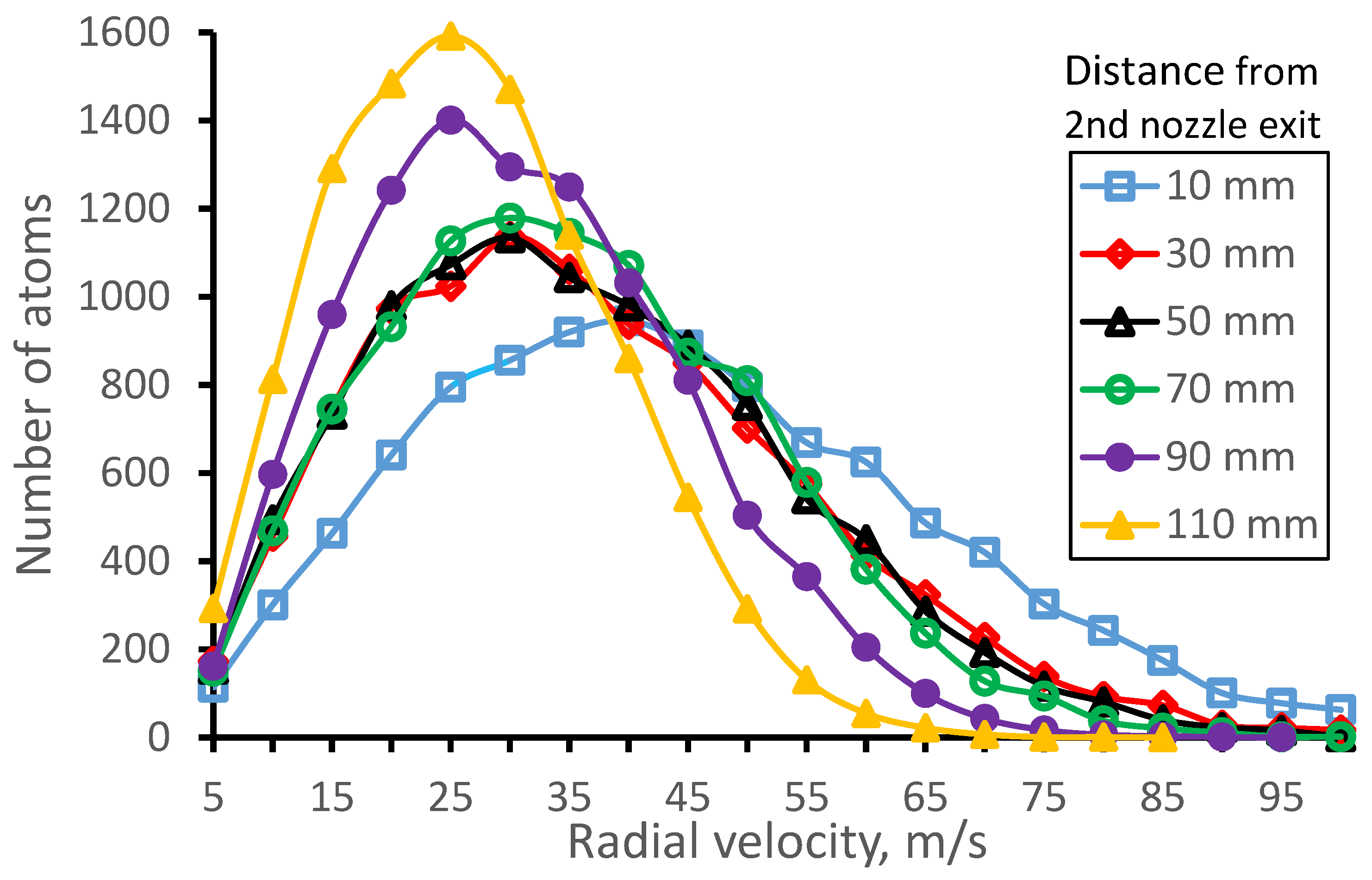
Results of the Monte-Carlo trajectory simulations for 164Dy atomic beam radial velocity distributions (averaged in the radial plane for the Laser-1 beam diameter of 10 mm) for different distances from the 2nd nozzle exit. The number of calculated atoms for each velocity distribution is 10,000.
Figure 19.
Results of the Monte-Carlo trajectory simulations for 164Dy atomic beam radial velocity distributions (averaged in the radial plane for the Laser-1 beam diameter of 10 mm) for different distances from the 2nd nozzle exit. The number of calculated atoms for each velocity distribution is 10,000.

Figure 20.
Results of the gas dynamic simulation for Mach number flow fields for double nozzle at different pumping speeds: (a) 650 l/s, (b) 1300 l/s, (c) 2600 l/s, (d) GSI nozzle. The stagnation gas cell pressure Pcell = 100 mbar, gas input (stagnation) pressure Pnoz = 81 mbar. The temperature of the gas cell and both nozzles is 296 K. Black arrowed lines show the gas flow direction.

Figure 21.
Results of the Monte-Carlo trajectory simulations of the fraction of the extracted from the gas cell 164Dy atomic beam inside the gas jet of 10 mm in diameter (it is the Laser-1 diameter) for different pumping speeds as a function of distance from the 2nd nozzle exit. Number of calculated atoms is 10,000 for each variant.

Figure 22.
Results of the Monte-Carlo trajectory simulations for 164Dy atomic beam longitudinal velocity spread (FWHM) for different pumping speeds as a function of the distance from the 2nd nozzle exit. The data averaged in the radial plane for the Laser-1 beam diameter of 10 mm. Number of calculated atoms is 10,000 for each variant.

Figure 23.
Results of the Monte-Carlo trajectory simulations of the fraction of the extracted from the gas cell 164Dy atomic beam inside the region of 10 mm in diameter (it is the Laser-1 diameter) for different input pressures Pnoz as a function of distance from the 2nd nozzle exit. Number of calculated atoms is 10,000 for each variant.

Figure 24.
Results of the Monte-Carlo trajectory simulations for 164Dy atomic beam longitudinal velocity spread (FWHM) for different input pressures Pnoz as a function of the distance from the 2nd nozzle exit. The data averaged in the radial plane for the Laser-1 beam diameter of 10 mm. Number of calculated atoms is 10,000 for each variant.

Figure 25.
Results of the Monte-Carlo trajectory simulations of the fraction of the extracted from the gas cell 164Dy atomic beam inside the region of 10 mm in diameter (it is the Laser-1 diameter) for two different gas cell pressures Pcell as a function of distance from the 2nd nozzle exit. Number of calculated atoms is 10,000 for each variant.

Figure 26.
Results of the Monte-Carlo trajectory simulations for 164Dy atomic beam longitudinal velocity spread (FWHM) for different input pressures Pnoz as a function of the distance from the 2nd nozzle exit. The data averaged in the radial plane for the Laser-1 beam diameter of 10 mm. Number of calculated atoms is 10,000 for each variant.

Figure 27.
Results of the Monte-Carlo trajectory simulations of the fraction extracted from the gas cell 164Dy atomic beam for different Laser-1 beam diameters as a function of distance from the 2nd nozzle exit. Number of calculated atoms is 10,000 for each variant.
Figure 27.
Results of the Monte-Carlo trajectory simulations of the fraction extracted from the gas cell 164Dy atomic beam for different Laser-1 beam diameters as a function of distance from the 2nd nozzle exit. Number of calculated atoms is 10,000 for each variant.

Figure 28.
Results of the Monte-Carlo trajectory simulations for 164Dy atomic beam longitudinal velocity spread (FWHM) for different Laser-1 beam diameters as a function of the distance from the 2nd nozzle exit. The data averaged in the radial plane for each Laser-1 beam diameter. Number of calculated atoms is 10,000 for each variant.

Figure 29.
Results of the Monte-Carlo trajectory simulations of the fraction of the extracted from the gas cell 253No atomic beam inside the gas jet of 10 mm in diameter (it is the Laser-1 diameter) for the gas cell pressure Pcell = 100 mbar, Pnoz = 81 mbar and Pbg = 2 × 10⁻² mbar as a function of distance from the 2nd nozzle exit. Number of calculated atoms is 10,000 for each case.

Figure 30.
Results of the Monte-Carlo trajectory simulations for 253No atomic beam longitudinal velocity spread (FWHM) for the gas cell pressure Pcell = 100 mbar, Pnoz = 81 mbar and Pbg = 2 × 10⁻² mbar as a function of the distance from the 2nd nozzle exit. The data averaged in the radial plane for the Laser-1 beam diameter of 10 mm. Number of calculated atoms is 10,000 for each case.

Figure 31.
Results of the Monte-Carlo trajectory simulations for 253No atomic beam longitudinal velocity distributions (averaged in the radial plane for the Laser-1 beam diameter of 10 mm) for different distances from the 2nd nozzle exit. The number of calculated atoms for each velocity distribution is 10,000.


Table 1.
Main design parameters of the double-nozzle device.
| 1st Nozzle | |
|---|---|
| Exit diameter | 3.5 mm |
| Throat diameter | 1.0 mm |
| Length of diverging cone | 2.5 mm |
| Connection tube between the 1st and 2nd nozzle | |
| Tube diameter | 3.5mm |
| Tube length | 3.0 mm |
| Inner tube in the 2nd nozzle | |
| Exit diameter | 2.0 mm |
| Inner entrance diameter | 3.5 mm |
| Inner total length | 6.0 mm |
| Supersonic part length | 4.0 mm |
| Out entrance diameter | 4.0 mm |
| Outer total length | 5.0 mm |
| Diverging 2nd nozzle | |
| Throat diameter | 3.6 mm |
| Diverging cone length | 20. mm |
| Exit diameter | 15.0 mm |
| Annual gap between nozzle throat and inner tube | 0.1 mm |
Disclaimer/Publisher’s Note: The statements, opinions and data contained in all publications are solely those of the individual author(s) and contributor(s) and not of MDPI and/or the editor(s). MDPI and/or the editor(s) disclaim responsibility for any injury to people or property resulting from any ideas, methods, instructions or products referred to in the content. |
© 2023 by the author. Licensee MDPI, Basel, Switzerland. This article is an open access article distributed under the terms and conditions of the Creative Commons Attribution (CC BY) license (https://creativecommons.org/licenses/by/4.0/).
Share and Cite
MDPI and ACS Style
Varentsov, V. Proposal of a New Double-Nozzle Technique for In-Gas-Jet Laser Resonance Ionization Spectroscopy. Atoms 2023, 11, 88. https://doi.org/10.3390/atoms11060088
AMA Style
Varentsov V. Proposal of a New Double-Nozzle Technique for In-Gas-Jet Laser Resonance Ionization Spectroscopy. Atoms. 2023; 11(6):88. https://doi.org/10.3390/atoms11060088
Chicago/Turabian StyleVarentsov, Victor. 2023. "Proposal of a New Double-Nozzle Technique for In-Gas-Jet Laser Resonance Ionization Spectroscopy" Atoms 11, no. 6: 88. https://doi.org/10.3390/atoms11060088
Note that from the first issue of 2016, this journal uses article numbers instead of page numbers. See further details here.