1. Introduction
Atom interferometry [
1,
2,
3] is a core technology for quantum metrology and quantum sensing [
4]. Its operating principle exploits the wave nature of matter in the same way that classical optical interferometers exploit the wave nature of light. In the type of atom interferometer considered here, an initial wavepacket is split into two pathways that are separated spatially. These pathways are then mirrored and recombined. The recombination maps an accumulated phase difference between the two pathways into population at the output ports as an interference pattern.
Since atoms have mass, this relative phase is affected by gravitational fields, acceleration, and rotation. This enables not only applications in fundamental physics [
5,
6,
7], but also direct practical implementations of gradiometers, gyroscopes, and inertial navigation sensors [
8,
9]. A second advantage, as well as a challenge of atomic matter waves, is that their wavelength is many orders of magnitude smaller than that of light, thus promising extremely high sensitivity, but making it difficult to implement “beamsplitters” and “mirrors” that can diffract at that scale. The highest precision can be reached through light–matter interaction [
10,
11]; specifically, the interaction of the atoms with counter-propagating laser fields. There are different regimes in which the atoms can absorb or emit photons, imparting momentum kicks [
12]. Most commonly, in the Raman regime, the change in momentum is associated with a change in the internal state of the atom [
13,
14,
15,
16], whereas in the Bragg regime, the atom remains in its internal ground state [
17,
18,
19,
20,
21].
Here, we consider the setup of an atomic fountain interferometer (AFI) [
21,
22,
23,
24]. We focus on the Bragg regime, which allows for higher momentum space separation and is less susceptible to ac-Stark and Zeeman shifts [
25]. A cloud of atoms with a well-defined initial momentum is launched into a 10 m tower [
26]. After the launch, counter-propagating laser beams with appropriately controlled amplitude and phase impart momentum kicks onto the atoms to implement a momentum space beamsplitter, mirror, and recombination. The scale of the atomic fountain architecture allows for time of flight on the order of seconds and, thus, achieves the largest interferometric space–time area to date.
The contrast of the interferometer, particularly in the Bragg regime, is constrained by the spread in the initial momentum of the atoms [
16,
27], as well as by deviations in the laser field intensity [
28]. Here, we quantify the expected contrast for different widths in the initial velocity distribution, and for variations in the pulse amplitude by
, for a sequence of
and
pulses. We further analyze the robustness of analytical pulse schemes using rapid adiabatic passage (RAP) [
29,
30]. These use linearly chirped laser pulses to transfer population between the momentum states. In the context of AFI, they have been demonstrated to achieve large momentum space separation [
30,
31]. RAP is inherently robust to deviations in the pulse amplitude. We show here that the combination of RAP and
and
pulses significantly enhances the robustness of the full interferometric scheme.
Going beyond standard analytic pulse shapes, such as Gaussians, more elaborate shapes have been demonstrated to improve robustness [
28,
32]. Finding appropriate pulse shapes is the focus of optimal control theory (OCT) [
33,
34,
35]. For atom interferometers in the Raman regime and two-level dynamics, the ability of optimal control to achieve robust pulses has been demonstrated [
32,
36,
37]. Optimal control has also been applied to Bose–Einstein condensates in atom interferometers [
38]. Here, we use Krotov’s method of optimal control [
39,
40,
41,
42] for an ensemble optimization [
43,
44,
45] to identify robust pulses for large momentum state separation in the Bragg regime. The ensemble optimization targets the average of a statistical ensemble of atoms with different initial velocities and experiencing different pulse amplitudes. We find that the most robust scheme overall uses optimized pulses driving transitions between the ground momentum state
and the first excited momentum state
corresponding to the momentum
. These optimized pulses are combined with analytical RAP pulses to amplify the momentum state separation, to the momentum state
corresponding to
, in our example.
This paper is organized as follows. In
Section 2, we describe the interaction of an atom with two counter-propagating laser beams inside an atomic fountain interferometer and derive its momentum space Hamiltonian in the Bragg regime.
Section 3 reviews two analytic pulse schemes: first, a train of
and
pulses, and second, a combination of
and
pulses and rapid adiabatic passage.
Section 4 analyzes the robustness of these schemes in terms of the expected contrast for varying pulse amplitudes and for initial velocities of varying uncertainties. In
Section 5, we describe the ensemble optimization approach used to improve the robustness of the analytical schemes. We analyze the resulting control fields and dynamics and compare the resulting robustness throughout the parameter landscape.
Section 6 concludes.
2. Model
In this paper, we consider an atomic fountain interferometer [
21,
24,
46] with light pulses in the Bragg regime [
17,
18,
19]. A cloud of ultracold Rubidium atoms with atomic mass
m is launched along the
z axis of a ten-meter tower [
26]. After the launch, the atoms are subjected to two counter-propagating laser fields with wave number
for a given laser wavelength
. These laser fields have tunable amplitude
,
and frequency
,
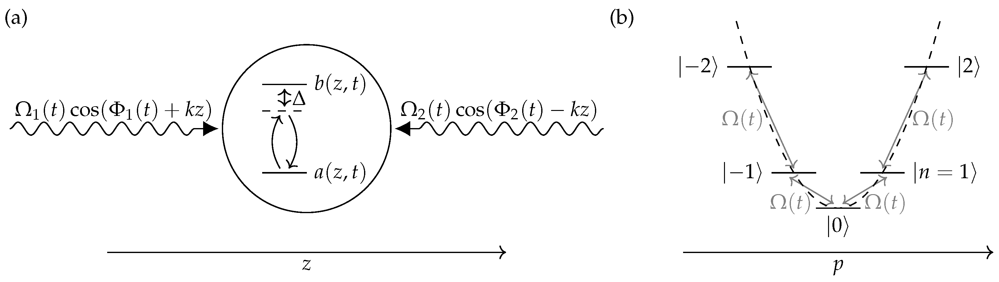
and are used to implement momentum space “beamsplitters” and “mirrors”. A schematic of the interaction for a single atom is shown in
Figure 1a.
The laser fields off-resonantly drive an internal electronic transition, e.g., the Rubidium D2 line
. The atom is described by the wave function
, where
and
are the
and
levels, respectively. For a large detuning
, the amplitude
of the excited state can be adiabatically eliminated. This results in an effective two-photon field with amplitude and phase
acting only on the ground state amplitude
[
47]. A transformation from coordinate space to momentum space shows that the effective field can change the momentum only in discrete units of
relative to the rest frame defined for the initial momentum
[
48,
49].
We thus consider the entire dynamics of the atom in momentum space, where the ground state
corresponds to the rest frame momentum
, and the Hilbert space is defined in terms of levels
corresponding to the momentum
. The Hamiltonian takes the form
The time-dependent energy levels are
with the two-photon recoil frequency
, the dimensionless initial momentum
, and the common light shift
. We consider here
and neglect the term proportional to
. Moreover, as it does not depend on
n, the common light shift
only contributes a global phase to the dynamics of the interferometer and can be dropped. Thus, we use
in the remainder of the paper.
The energy levels
form the parabolic momentum ladder shown in
Figure 1b. These levels are shifted by the angular frequency
of the driving field. An appropriate frequency can shift neighboring levels into resonance, which then allows the effective amplitude
to transfer population. A nonzero value of
, that is, a nonzero momentum of the atom relative to the rest frame, would result in an effective detuning of this momentum space transition.
The factor
in Equation (
2) accounts for deviations of the effective pulse amplitude
from the optimal value, e.g., due to misalignment of the position of the atomic cloud relative to the cross section of the laser pulse. By default, we take
. The effective amplitude
is allowed to be complex-valued only in the context of optimal control. Optimizing the real and imaginary part of a complex-valued
independently is equivalent to optimizing a real-valued field amplitude and phase. That is, the complex phase of
expresses a deviation from the phase
in Equation (
4).
For complete generality, we express the energies and in units of . Using the corresponding time unit of makes the Schrödinger equation dimensionless. For Rb-87, with a laser wavelength of nm, we have kHz, and a corresponding time unit of approximately s.
3. Analytical Pulse Schemes
A full atomic fountain interferometer ideally consists of the following steps:
- 1.
Split the initial state into a superposition of and . In the example here, we use , corresponding to a momentum state separation of . This is the analog of a beamsplitter in a classic interferometer. The splitting may further be subdivided as:
- (a)
Perform an initial splitting, from to a superposition of and .
- (b)
Amplify the momentum state separation by transferring population from to , resulting in a superposition of and .
- 2.
Let the atoms evolve freely as they travel up the tower. During this time, an external gravitational field or acceleration may introduce a differential phase between the states and .
- 3.
Swap the complex amplitudes of the and states. This is the analog of a mirror in a classic interferometer. It may be subdivided as in step 1:
- (a)
De-amplify the population from to , so that the interferometer is in a superposition of and .
- (b)
Swap the amplitude of and .
- (c)
Amplify the population from to , which again brings the interferometer into a superposition of and , with swapped amplitudes relative to the end of step 2.
- 4.
Let the atoms continue to evolve freely as they descend the tower, potentially accumulating a further differential phase.
- 5.
Recombine the state into a superposition of and . This would be subdivided as:
- (a)
De-amplify the population from to , resulting in a superposition of and .
- (b)
Coherently
recombine the amplitudes of
and
by applying the inverse process of step 1 (a). For a phase
accumulated in steps 2 and 4 that is a multiple of
, this results in the population returning to the ground state
. More generally, the final state is a superposition of
and
, depending on the accumulated phase
, with the population in
as
and the population in
as
.
There are possible variations of the above procedure. For example, the interferometer could be designed symmetrically, where, in step 1, the initial state is split into a superposition of
and
[
16,
37]. However, this generally requires additional laser fields, as a single pair of counter-propagating fields cannot address both branches of the interferometer. Furthermore, the subdivision into a splitting between levels
and
, which is then amplified to a superposition between
and
, could be generalized so that the initial splitting is between
and some higher level
with
, and where
is then still further amplified to
. Physically, this situation would occur with higher-order Bragg pulses [
46], where the final state of the interferometer would then be a superposition of
and
. Here, we consider only first-order Bragg pulses, which change the momentum in steps of
, following the setup in Reference [
26].
The interferometer signal contrast is defined as
with
and
. In a non-ideal system, with imperfect splitting and mirror operations, population may be lost from the
,
subspace at final time, and the population in the ground state may deviate from the ideal Equation (
5), resulting in a loss of contrast.
3.1. Train of and Pulses
A straightforward approach is to use a train of
- and
-pulses to manipulate the wave function of the atoms [
26,
46]. Each pulse in this train uses a fixed laser frequency
that is resonant with a specific transition from level
to
. The transition is resonant for
Plugging this into Equation (
4) produces (
)
with
. The second term contributes only a global phase and can be dropped.
Steps 1–5 of the full interferometer with a maximum separation of
are implemented by a series of
and
pulses, as shown in the top of
Figure 2b. Each pulse is a Blackman shape of duration
, which corresponds to roughly 150 µs for Rb-87 and a laser wavelength of 780 nm. Neglecting all but the two resonant levels for each pulse allows to calculate the pulse amplitude
analytically. The first pulse is a
pulse with an amplitude chosen such that
in order to produce a
superposition of
and
. The pulse amplitude is
, corresponding to
kHz.
Subsequent pulses are
-pulses at twice the amplitude of Equation (
9) that fully transfer population between neighboring levels, respectively swap the population of
and
at the center of the scheme. The final
pulse recombines the population. For simplicity, we do not show the free time evolution in the scheme. The phase that would be accumulated during the free time evolution, when the interferometer is at maximum momentum separation, can be numerically emulated by applying an instantaneous phase kick to the
-component of the wave function, as indicated in
Figure 2b. The shown dynamics are for
. A kick with a value of
only affects the population in the central swap pulse and at final time. The resulting final time population in
is shown in
Figure 2c and matches Equation (
5).
The use of
and
pulses is slightly complicated by the presence of the additional levels. According to Equation (
8), the transition to the next higher or lower levels is detuned by
, which is not completely negligible compared to the amplitude of the
pulse,
. The additional levels induce an effective shift in the two-level system that can be compensated with a modified pulse amplitude. In
Figure 2a, we numerically analyze the fidelity of the scheme depending on a scaling factor for the empirical pulse amplitude
relative to the analytical amplitude
defined in Equation (
9) for an ideal two-level system. We find that an increase in pulse amplitude by 1% results in the lowest error. Thus, we include this correction in the scheme shown in
Figure 2b, as well as in all future
and
pulse amplitudes.
3.2. Rapid Adiabatic Passage
An alternative scheme formulated in References [
30,
31] is to replace the train of pulses with a single pulse implementing rapid adiabatic passage (RAP) with a linear frequency chirp, respectively, a phase of
where
is the chirp rate and
is a time offset relative to the start of the pulse. Plugging the phase into Equation (
4) with
results in
An example for the dynamic energy levels
and the resulting population dynamics is depicted in
Figure 3a, with a chirp rate
. Neighboring levels cross at time intervals of
, see the center of panel (a), resulting in a population transfer as shown in the top of panel (a).
For the given chirp rate, the RAP pulse we employ here is as short as possible, while still transferring momentum with high fidelity. This includes a finite switch on/off from/to zero. The transfer fidelity in this case depends on the specific switch-on time and shape, and an offset
in Equation (
10) that determines the zero point of the induced energy shift. Effectively, this offset accounts for the fact that the RAP dynamics start only when the field reaches some minimum amplitude. We use a Blackman shape for the switch-on/off and numerically determined the switch-on time
, the offset
and the peak amplitude via an optimization of the transfer fidelity using the Nelder–Mead method. We found
for a switch-on/off time of
and a peak amplitude of
, corresponding to roughly
kHz for Rb-87 and a laser wavelength of 780 nm. The resulting envelope
is shown at the bottom of panel (a) with
and
indicated by the dotted green and blue lines, respectively.
A noteworthy feature of the RAP population transfer is that it is relatively insensitive to the pulse amplitude, promising some degree of robustness when used as part of an atom interferometric scheme. It also allows to transfer population to arbitrarily high momentum states, for as long as the constant chirp can be maintained. However, compared to the “Rabi” scheme consisting only of
and
pulses, it is relatively more challenging to use RAP for the initial splitting, the central swap of
and
, or the final recombination required for the full scheme. Thus, we combine it with a
pulse to achieve the initial splitting, followed by another
pulse to achieve sufficient separation for the RAP scheme to transfer population to maximum separation. In the center of the scheme, three
pulses swap the amplitude, and, finally, a
pulse and a
pulse perform the recombination. The full scheme is depicted in
Figure 3b.
Compared to the sequence of
and
pulses in
Figure 2b, the required pulse area for RAP is significantly larger; see the amplitudes shown in the top of both panels. Further compressing the RAP pulses in time would cause increasingly non-adiabatic dynamics and a breakdown of the population transfer, shown in
Figure 3a. The fast oscillations that can be seen at the top of panel (a), are already non-adiabatic effects, showing that the chosen parameters approach the time limit for RAP. Thus, the RAP scheme in
Figure 3b is slightly slower than the comparable Rabi scheme of
and
pulses in
Figure 2b, with a combined duration
versus
. In general, this should have a negligible effect on the overall interferometer, as the free time of flight, measured in seconds [
26], dominates the time
T for splitting, mirroring, and recombination, measured in milliseconds.
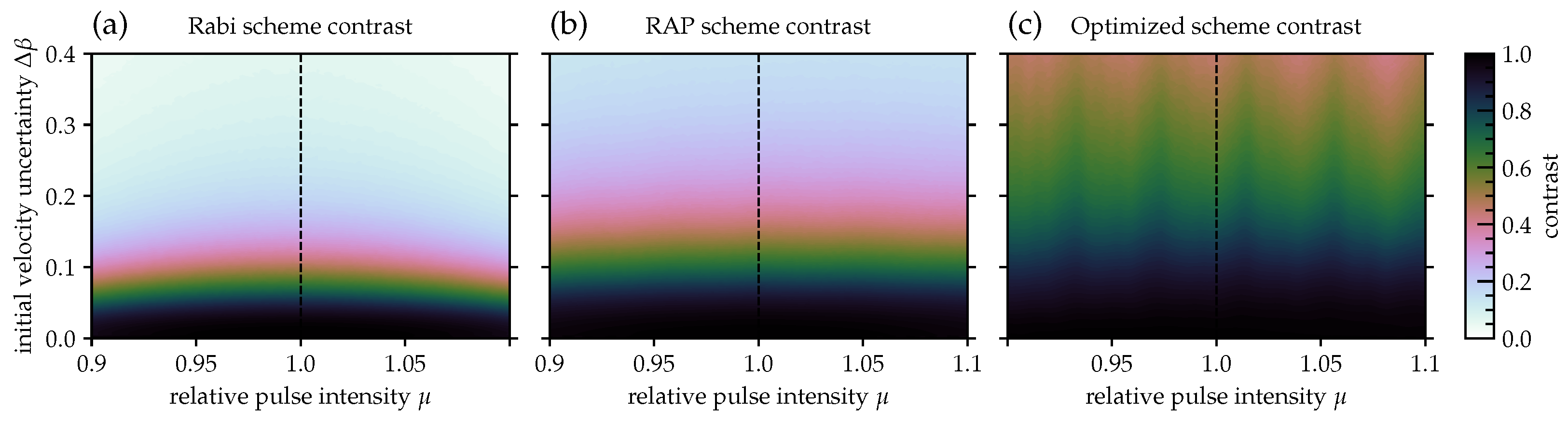
4. Robustness
The dynamics shown in
Figure 2 and
Figure 3 for the analytical Rabi and RAP scheme are for ideal parameters, i.e., zero velocity relative to the rest frame and the ideal pulse amplitude,
and
in Equations (
2) and (
4), where
now includes the correction of
, obtained from
Figure 2a. We can now analyze the robustness of the different interferometric schemes with respect to variations in atom velocity and pulse amplitude. Since the width of the atomic cloud is small relative to the cross section of the laser pulse, deviations from the ideal amplitude are most likely due to the position of the atomic cloud within the laser field, or due to variations in the overall laser amplitude itself, but are the same for all atoms in the ensemble. On the other hand, the velocity relative to the rest frame varies within the ensemble. It is normal-distributed with a variance that depends on the temperature of the atomic cloud.
In
Figure 4a,b, we show the expectation value of the contrast for static deviations from the optimal pulse amplitude by
(
) and for
(the momentum relative to the rest frame in units of
) drawn from a normal distribution with a standard deviation between 0 and
. For every point in this robustness landscape, we evaluated
N = 50,000 samples to find
where
is the population in the ground state at final time,
is the differential phase accumulated between the two branches of the interferometer, and
is a value of
drawn from the distribution of width
. The expectation value of the contrast shown in
Figure 4 is then
cf. Equation (
6).
We find that the contrast is relatively robust with respect to deviations from the optimal pulse amplitude, but decays quickly for broader distributions in the atomic velocity. Using the scheme of
and
Rabi pulses,
Figure 2b, the contrast crosses the 50% mark for a standard deviation of
and effectively approaches zero for
. Taking advantage of rapid adiabatic passage (RAP) with the scheme shown in
Figure 3b, we find a measurable improvement in robustness. The sensitivity to deviations in
nearly disappears, and the loss of contrast, due to
, is reduced by at least a factor of
. That is, a 50% loss of contrast occurs at
. Even at
, the contrast is still ≈12%.
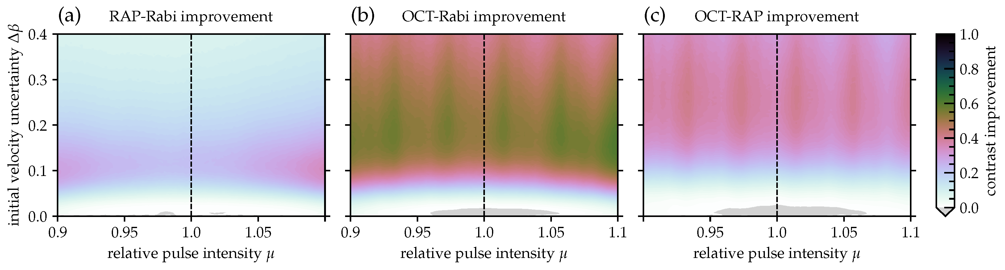
The change in contrast between the Rabi and RAP schemes is quantified in
Figure 5a. The RAP scheme improves on the Rabi scheme by an increase in contrast of up to 0.35. This maximum improvement is reached for deviations of the pulse amplitude near 10% and a standard deviation of
in the initial momentum of the atoms in the ensemble. The light gray areas in the plot mark a loss of contrast for some points near
. These losses are comparatively negligible at
.
5. Optimal Control for Robust Pulse Schemes
To further increase the robustness, we now consider the use of optimal control theory (OCT). We optimize the specific steps of the interferometric scheme in
Section 3 separately: the initial splitting into a superposition of
and
, step 1 (a), the amplification from
to
, steps 1 (b) and 3 (c), the de-amplification, steps 2 (a) and 5 (a), and the swap of amplitudes
and
, step 3 (b).
It can be shown [
47] that any relative phase introduced by the amplification and de-amplification cancels out. Thus, these steps can be implemented with an optimization functional that only considers populations, e.g., for the amplification step,
where the components of the vectors
and
are the populations in the different momentum levels for the propagated state and the target state, respectively. A relative phase introduced by the initial splitting has to be compensated for in the recombination step. This is automatic if we perform the initial splitting between levels
and
by optimizing for an effective
pulse,
up to a global phase, i.e., using a square-modulus overlap functional [
50]. This ensures that the same optimized pulse targeting step 1 (a) in
Section 3 can also be used for the final recombination, step 5 (b).
For the amplification and de-amplification, we optimized starting from a RAP pulse that transfers
, respectively
, cf.
Figure 3a. The optimization modifies the envelope
in order to minimize the population functional in Equation (
14). In principle, the chirp rate
in Equation (
10) could also be made time-dependent. Instead, we left the chirp rate constant and allowed
to be complex-valued.
To make the optimized pulses robust with respect to deviations in the pulse amplitude and variations in the initial velocity, we employed an ensemble optimization [
43,
44,
45]. That is, we considered multiple copies of the Hamiltonian, Equation (
2), each with different parameters
and
. We then optimized over the average of the ensemble. In order to cover a large area of the parameter landscape, we considered an ensemble of 1024 points, split into 64 batches of 16 points each. Individual points were drawn randomly from a normal distribution around
and
with
. For each batch of points, we performed an ensemble optimization with Krotov’s method [
39,
40,
41,
42,
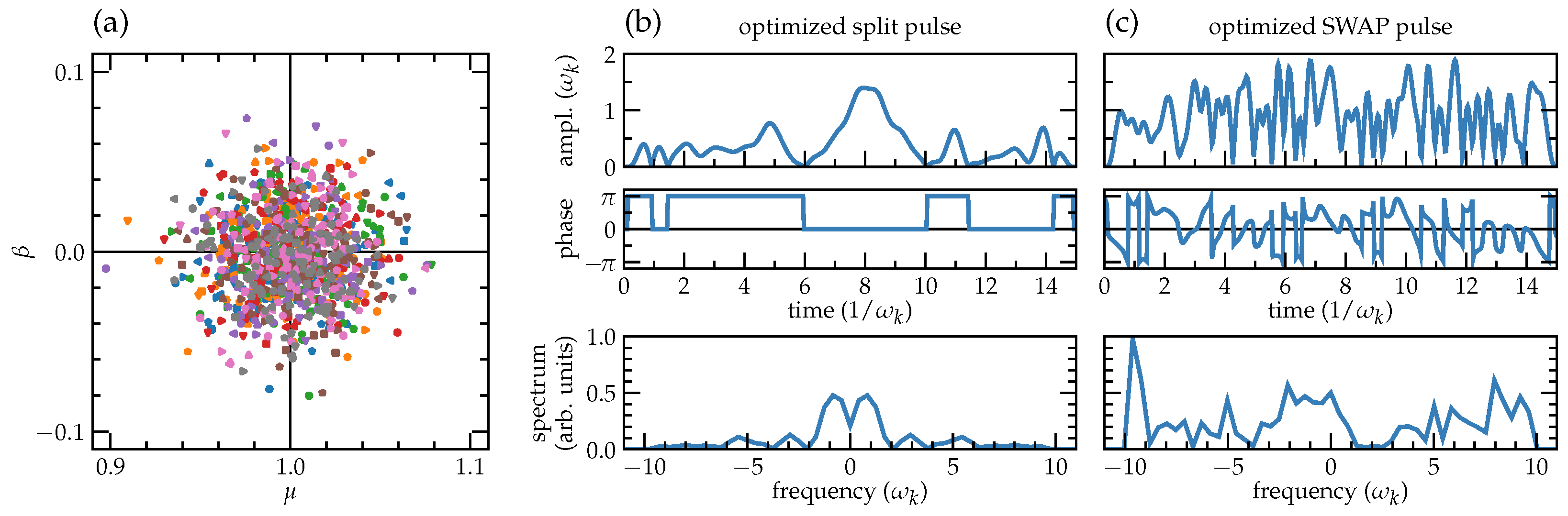
47] for 1000 iterations before moving to the next batch. The procedure continued to loop around the batches until convergence was reached, that is, there was no significant improvement in the fidelity reachable within 1000 iterations, compared to the previous batch.
The sampling points
and
for the different batches are shown in
Figure 6a. We found the chosen width of the sampling point distribution
to be the maximum width for which an average fidelity on the order of
is achievable for the individual components of the interferometer.
As we wanted to explore the limits of robustness achievable via optimal control, we did not restrict the optimized control fields to amplitudes or spectral widths that are easily obtained with current experimental setups. At the same time, we wanted to avoid entirely unrealistic parameter regimes. Thus, we placed a bound on the pulse amplitude at , roughly a factor of six higher than the typical amplitude required for a Rabi pulse, and roughly twice the amplitude of the RAP pulses used for the momentum transfer. Similarly, the spectral width was limited to . Both the amplitude and the spectral width are well within an order of magnitude of the current capabilities of the atomic fountain experimental setup.
The resulting pulses for the initial splitting (an effective
pulse), and for the swap are shown in
Figure 6b,c. The effective
pulse is a relatively simple pulse shape. In particular, it does not require a time-dependent phase, i.e., the imaginary part of the control field
. The swap is more difficult to realize, and saturates the amplitude and spectral limits placed on the control that allow to reach the almost perfect gate fidelity.
For the optimization of the RAP pulse that amplifies and de-amplifies the momentum state separation, we found that the optimization only added negligible corrections to the pulse shape. This is a testament to the inherent robustness of rapid adiabatic passage. In fact, when combining the optimized components of the interferometer into a full scheme, and analyzing the resulting robustness, we observed no clear advantage in using the RAP pulses with an optimized amplitude. Thus, the full “optimized” pulse scheme uses the pulse shown in
Figure 6b as the initial and final component, and the pulse in
Figure 6c as the center swap, but analytical RAP pulses otherwise.
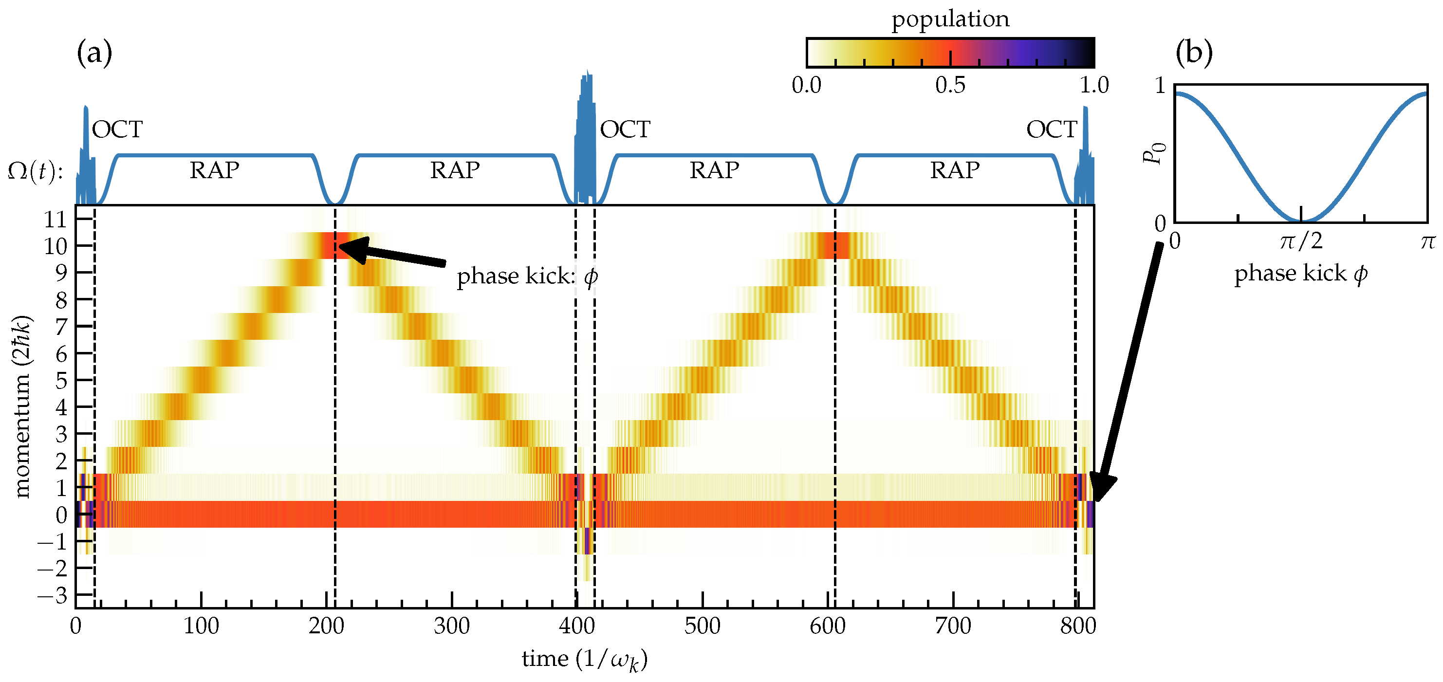
The full optimized scheme and the resulting dynamics in the ideal case (
,
) are shown in
Figure 7. We can see that there are visible deviations from the simple analytic schemes in
Figure 2 and
Figure 3. In particular, the optimized splitting and swap pulses populate outside the two-level subspace
,
, at intermediary times. The final time population in
differs measurably from the analytical schemes, reaching 0.93 in
Figure 7c. However, since the population for a differential phase of
is still 0.001, this does not affect
contrast, which is still ≈1, according to Equation (
6).
The contrast of the full scheme for values of
, and for an initial momentum drawn from a normal distribution with
, is shown in
Figure 4c. We observe a considerable improvement. The limit for 50% contrast is pushed well beyond
. Even for
, the minimum contrast is still 41% or higher. Remarkably, the enhancement in robustness extends far beyond the value of
that was used in the ensemble optimization. The improvement relative to the fully analytical Rabi and RAP schemes is shown in
Figure 5b,c. Within the explored parameter regime, the maximum absolute improvements in contrast are 0.61 and 0.41, respectively. The losses marked in light gray are
in both cases.
6. Conclusions and Outlook
We have numerically analyzed the expected robustness of several complete schemes for an atomic fountain interferometer reaching a momentum state separation of . For purely analytic schemes, we found that robustness can be increased considerably by using rapid adiabatic passage to transfer population after the initial separation. This comes at the cost of an increase in pulse area, reaching about the limit of current experimental capabilities. However, the use of rapid adiabatic passage fundamentally enables the achievement of arbitrarily high momentum state separation and preserves very high robustness, as long as the linear chirp of the laser frequency can be maintained. In fact, we did not find that the robustness of the RAP pulses can be substantially improved by optimal control. In contrast, optimal control theory can significantly improve the initial splitting and swapping of amplitudes in the middle of the interferometric scheme. Again, this comes at the cost of an increase in pulse area. The optimized pulses presented here are on the border of current experimental capabilities in terms of pulse amplitude and spectral width, but well within an order of magnitude. Thus, we expect these pulses to be realizable in the future.
Combining optimized pulses with rapid adiabatic passage into a full scheme results in a very robust scheme, if the uncertainty of the initial momentum of the atoms in the interferometer is . Even for relatively large uncertainties of or higher, a contrast of 40% is maintained. Due to the combination with analytic RAP pulses, we expect this contrast to be maintained even for much higher momentum state separation.
The optimized scheme identified here opens several avenues for future exploration. For implementation in the laboratory, the pulse area and spectral width of the optimized pulses would have to be reduced by at least a factor of three. As the goal here was to identify maximally robust pulses without stringent constraints, the limits of robustness within currently achievable constraints of a specific experimental setup have not been fully probed. As RAP was identified here as a core component of a robust scheme with large momentum state separation, it would be worthwhile to consider the combination of RAP with other two-level control schemes, such as those derived from nuclear magnetic resonance [
51].
We have assumed here that the deviations in the pulse amplitude are homogeneous, i.e., the atomic cloud is small relative to the cross section of the laser. Further, we have assumed that there are no time-dependent fluctuations in the laser for the duration of the pulse scheme, on the order of milliseconds. Strategies for mitigating time-dependent noise will be considered in future work. Spatial distortions in the laser profile could be taken into account by extending the model beyond plane waves [
52].
More generally, the sensitivity of the interferometer could be enhanced by exploiting correlation between the atoms, e.g., spin squeezing [
53,
54,
55,
56]. We have applied optimal control to the creation of such squeezed states [
57]. Going forward, we would like to explore the use of optimal control to further enhance the robustness of correlated atoms in atom interferometric schemes, including alternative realizations, such as lattice guided [
49] and tractor atom interferometers [
58].


