
A Radio-Frequency Ion Trap System for the Multi-Reflection Time-of-Flight Mass Spectrometer at SHANS and Its Offline Commissioning

 , , and
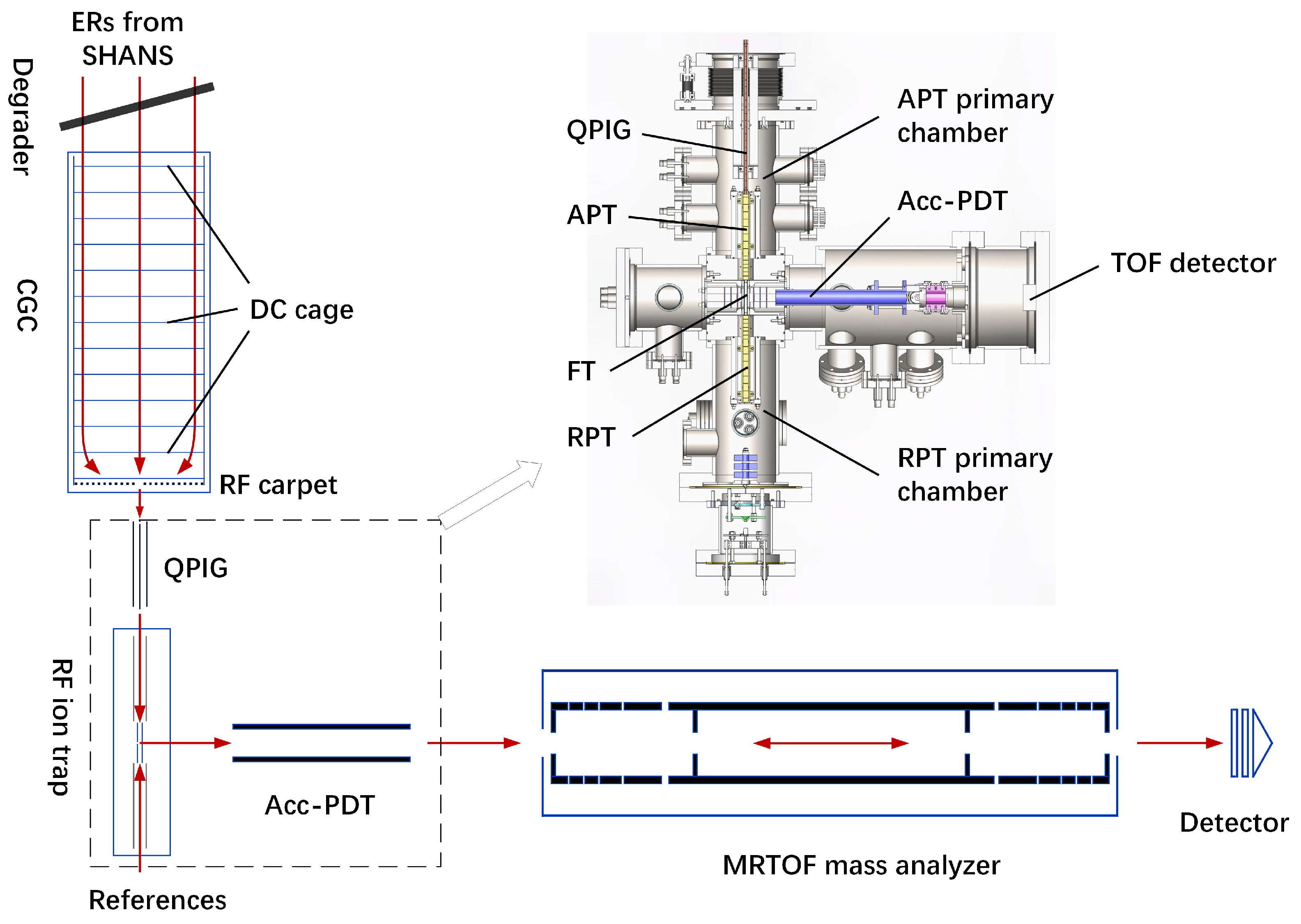
Abstract
:1. Introduction
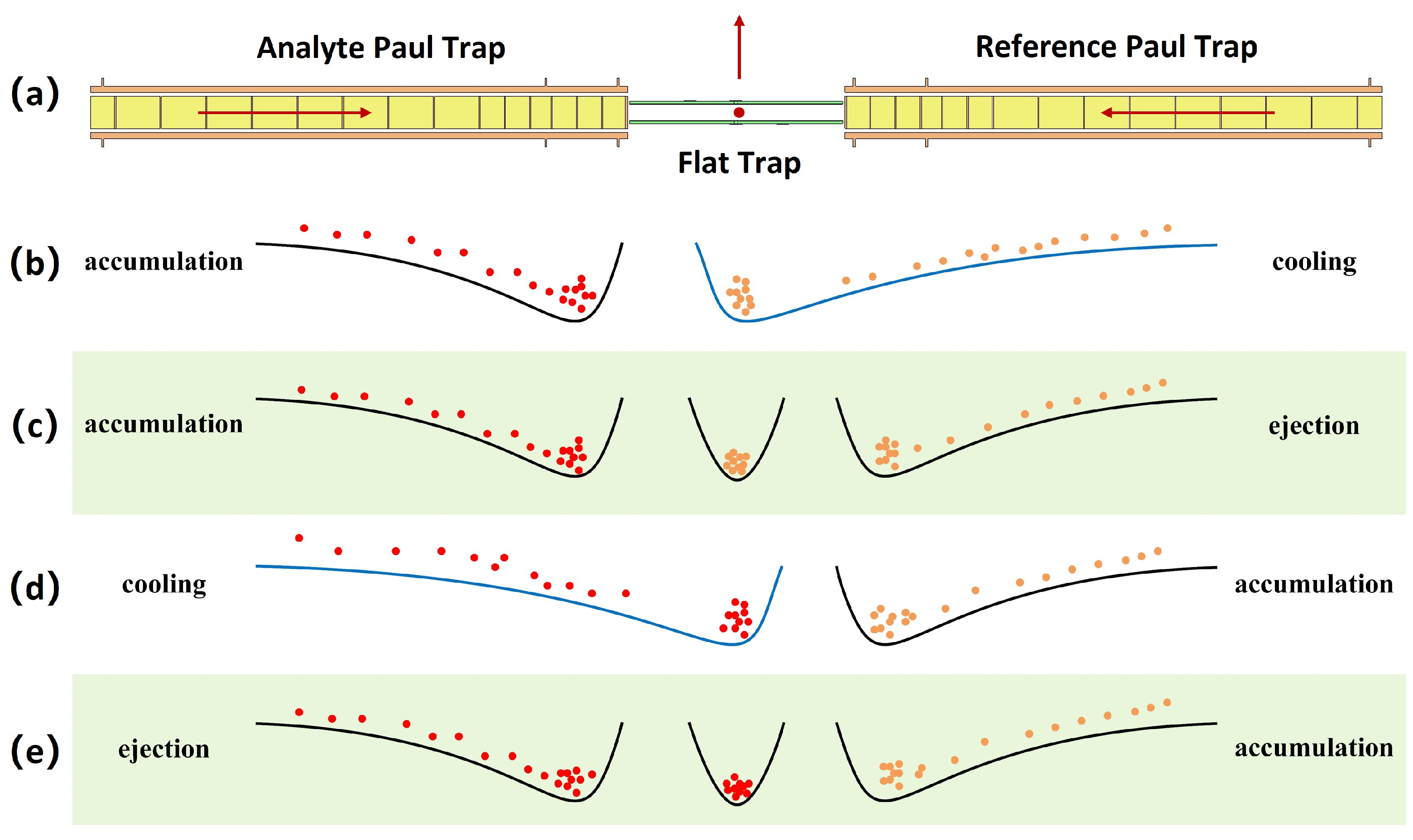
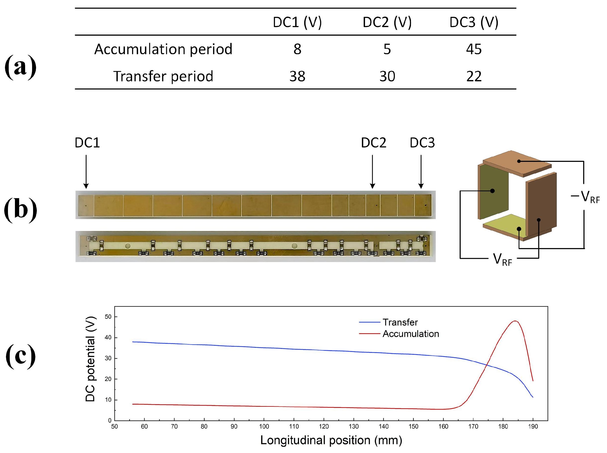
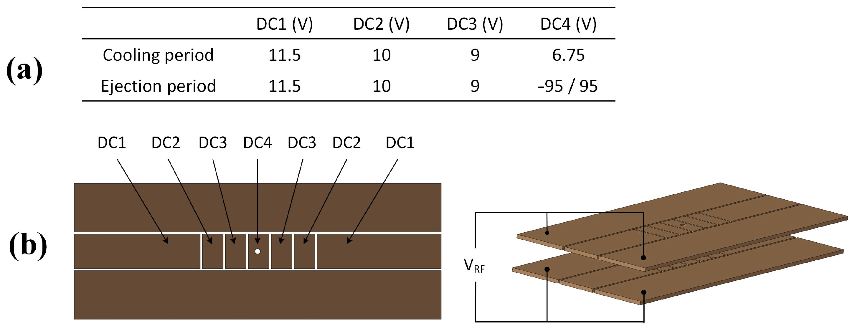
2. Experimental Setup
3. Offline Commissioning
4. Summary
Author Contributions
Funding
Data Availability Statement
Acknowledgments
Conflicts of Interest
References
- Wolf, R.N.; Beck, D.; Blaum, K.; Bohm, C.; Borgmann, C.; Breitenfeldt, M.; Herfurth, F.; Herlert, A.; Kowalska, M.; Kreim, S.; et al. On-line separation of short-lived nuclei by a multi-reflection time-of-flight device. Nucl. Instrum. Methods A 2012, 686, 82–90. [Google Scholar] [CrossRef]
- Dickel, T.; Plaß, W.R.; Becker, A.; Czok, U.; Geissel, H.; Haettner, E.; Jesch, C.; Kinsel, W.; Petrick, M.; Scheidenberger, C.; et al. A high-performance multiple-reflection time-of-flight mass spectrometer and isobar separator for the research with exotic nuclei. Nucl. Instrum. Methods A 2015, 777, 172–188. [Google Scholar] [CrossRef]
- Schury, P.; Wada, M.; Ito, Y.; Arai, F.; Naimi, S.; Sonoda, T.; Wollnik, H.; Shchepunov, V.A.; Smorra, C.; Yuan, C. A high-resolution multi-reflection time-of-flight mass spectrograph for precision mass measurements at RIKEN/SLOWRI. Nucl. Instrum. Methods B 2014, 335, 39–53. [Google Scholar] [CrossRef]
- Schury, P.; Wada, M.; Ito, Y.; Kaji, D.; Arai, F.; MacCormick, M.; Murray, I.; Haba, H.; Jeong, S.; Kimura, S.; et al. First online multireflection time-of-flight mass measurements of isobar chains produced by fusion-evaporation reactions: Toward identification of superheavy elements via mass spectroscopy. Phys. Rev. C 2017, 95, 011305. [Google Scholar] [CrossRef]
- Hirsh, T.Y.; Paul, N.; Burkey, M.; Aprahamian, A.; Buchinger, F.; Caldwell, S.; Clark, J.A.; Levand, A.F.; Ying, L.L.; Marley, S.T.; et al. First operation and mass separation with the CARIBU MR-TOF. Nucl. Instrum. Methods B 2016, 376, 229–232. [Google Scholar] [CrossRef]
- Kolhinen, V.S.; Eronen, T.; Gorelov, D.; Hakala, J.; Jokinen, A.; Jokiranta, K.; Kankainen, A.; Koikkalainen, M.; Koponen, J.; Kulmala, H.; et al. Recommissioning of JYFLTRAP at the new IGISOL-4 facility. Nucl. Instrum. Methods B 2013, 317, 506–509. [Google Scholar] [CrossRef]
- Chauveau, P.; Delahaye, P.; De France, G.; El Abir, S.; Lory, J.; Merrer, Y.; Rosenbusch, M.; Schweikhard, L.; Wolf, R.N. PILGRIM, a Multi-Reflection Time-of-Flight Mass Spectrometer for SPIRAL2-S3 at GANIL. Nucl. Instrum. Methods B 2016, 376, 211–215. [Google Scholar] [CrossRef]
- Tian, Y.L.; Wang, Y.S.; Wang, J.Y.; Zhou, X.H.; Huang, W.X. Designing a multi-reflection time-of-flight mass analyzer for LPT. Int. J. Mass Spectrom. 2016, 408, 28–32. [Google Scholar] [CrossRef]
- Huang, W.X.; Tian, Y.L.; Wang, Y.S.; Wang, J.Y.; Zhou, X.H. Optimization of multi-reflection time-of-flight mass analyzer operating in in-trap-lift mode. Radiat. Detect. Technol. Methods 2018, 2, 1. [Google Scholar] [CrossRef]
- Yoon, J.W.; Park, Y.H.; Im, K.B.; Kim, G.D.; Kim, Y.K. Design study for a multi-reflection time-of-flight mass spectrograph for very short lived nuclei. In Proceedings of the Conference on Advances in Radioactive Isotope Science (ARIS2014), Tokyo, Japan, 1–6 June 2014. [Google Scholar] [CrossRef]
- Liu, B.; Brodeur, M.; Burdette, D.P.; Kelly, J.M.; Kim, T.; Long, J.; O’Malley, P.D. The performance of the commissioned Notre Dame multi-reflection time-of-flight mass spectrometer. Nucl. Instrum. Methods A 2021, 985, 164679. [Google Scholar] [CrossRef]
- Reiter, M.; Andrés, S.A.S.; Bergmann, J.; Dickel, T.; Dilling, J.; Jacobs, A.; Kwiatkowski, A.; Plaß, W.; Scheidenberger, C.; Short, D.; et al. Commissioning and performance of TITAN’s Multiple-Reflection Time-of-Flight Mass-Spectrometer and isobar separator. Nucl. Instrum. Methods A 2021, 1018, 165823. [Google Scholar] [CrossRef]
- Yavor, M.I.; Gall, N.R.; Muradymov, M.Z.; Pomozov, T.V.; Kurnin, I.V.; Monakov, A.G.; Arsenev, A.N.; Oganessian, Y.T.; Karpov, A.V.; Rodin, A.M.; et al. Development of a mass spectrometer for high-precision mass measurements of superheavy elements at JINR. J. Instrum. 2022, 17, P11033. [Google Scholar] [CrossRef]
- Huang, W.X.; Wang, Y.S.; Tian, Y.L.; Wang, J.Y.; Wang, Y.; Gan, Z.G.; Xu, H.S. Offline commissioning and performance of a multi-reflection time-of-flight mass analyzer with a new configuration. Nucl. Instr. Methods A 2023, 1047, 167825. [Google Scholar] [CrossRef]
- Wienholtz, F.; Beck, D.; Blaum, K.; Borgmann, C.; Breitenfeldt, M.; Cakirli, R.B.; George, S.; Herfurth, F.; Holt, J.D.; Kowalska, M.; et al. Masses of exotic calcium isotopes pin down nuclear forces. Nature 2013, 498, 346–349. [Google Scholar] [CrossRef] [PubMed]
- Atanasov, D.; Ascher, P.; Blaum, K.; Cakirli, R.B.; Cocolios, T.E.; George, S.; Goriely, S.; Herfurth, F.; Janka, H.T.; Just, O.; et al. Precision Mass Measurements of 129–131Cd and Their Impact on Stellar Nucleosynthesis via the Rapid Neutron Capture Process. Phys. Rev. Lett. 2015, 115, 232501. [Google Scholar] [CrossRef]
- Rosenbusch, M.; Ascher, P.; Atanasov, D.; Barbieri, C.; Beck, D.; Blaum, K.; Borgmann, C.; Breitenfeldt, M.; Cakirli, R.B.; Cipollone, A.; et al. Probing the N = 32 Shell Closure below the Magic Proton Number Z = 20: Mass Measurements of the Exotic Isotopes 52,53K. Phys. Rev. Lett. 2015, 114, 202501. [Google Scholar] [CrossRef]
- Leistenschneider, E.; Reiter, M.P.; Ayet San Andrés, S.; Kootte, B.; Holt, J.D.; Navrátil, P.; Babcock, C.; Barbieri, C.; Barquest, B.R.; Bergmann, J.; et al. Dawning of the N = 32 Shell Closure Seen through Precision Mass Measurements of Neutron-Rich Titanium Isotopes. Phys. Rev. Lett. 2018, 120, 062503. [Google Scholar] [CrossRef]
- Ito, Y.; Schury, P.; Wada, M.; Arai, F.; Haba, H.; Hirayama, Y.; Ishizawa, S.; Kaji, D.; Kimura, S.; Koura, H.; et al. First Direct Mass Measurements of Nuclides around Z = 100 with a Multireflection Time-of-Flight Mass Spectrograph. Phys. Rev. Lett. 2018, 120, 152501. [Google Scholar] [CrossRef] [PubMed]
- Schury, P.; Niwase, T.; Wada, M.; Brionnet, P.; Chen, S.; Hashimoto, T.; Haba, H.; Hirayama, Y.; Hou, D.S.; Iimura, S.; et al. First high-precision direct determination of the atomic mass of a superheavy nuclide. Phys. Rev. C 2021, 104, L021304. [Google Scholar] [CrossRef]
- Wolf, R.N.; Beck, D.; Blaum, K.; Bohm, C.; Borgmann, C.; Breitenfeldt, M.; Chamel, N.; Goriely, S.; Herfurth, F.; Kowalska, M.; et al. Plumbing Neutron Stars to New Depths with the Binding Energy of the Exotic Nuclide 82Zn. Phys. Rev. Lett. 2013, 110, 041101. [Google Scholar] [CrossRef]
- Welker, A.; Althubiti, N.A.S.; Atanasov, D.; Blaum, K.; Cocolios, T.E.; Herfurth, F.; Kreim, S.; Lunney, D.; Manea, V.; Mougeot, M.; et al. Binding Energy of 79Cu: Probing the Structure of the Doubly Magic 78Ni from Only One Proton Away. Phys. Rev. Lett. 2017, 119, 192502. [Google Scholar] [CrossRef] [PubMed]
- Niwase, T.; Watanabe, Y.X.; Hirayama, Y.; Mukai, M.; Schury, P.; Andreyev, A.N.; Hashimoto, T.; Iimura, S.; Ishiyama, H.; Ito, Y.; et al. Discovery of New Isotope 241U and Systematic High-Precision Atomic Mass Measurements of Neutron-Rich Pa-Pu Nuclei Produced via Multinucleon Transfer Reactions. Phys. Rev. Lett. 2023, 130, 132502. [Google Scholar] [CrossRef]
- Zhang, Z.Y.; Ma, L.; Gan, Z.G.; Huang, M.H.; Huang, T.H.; Li, G.S.; Wu, X.L.; Jia, G.B.; Yu, L.; Yang, H.B.; et al. A gas-filled recoil separator, SHANS. Nucl. Instrum. Methods B 2013, 317, 315–318. [Google Scholar] [CrossRef]
- Gan, Z.G.; Huang, W.X.; Zhang, Z.Y.; Zhou, X.H.; Xu, H.S. Results and perspectives for study of heavy and super-heavy nuclei and elements at IMP/CAS. Eur. Phys. J. A 2022, 58, 158. [Google Scholar] [CrossRef]
- Schury, P.; Ito, Y.; Rosenbusch, M.; Miyatake, H.; Wada, M.; Wollnik, H. Improving wide-band mass measurements in a multi-reflection time-of-flight mass spectrograph by usage of a concomitant measurement scheme. Int. J. Mass Spectrom. 2018, 433, 40–46. [Google Scholar] [CrossRef]
- Wang, J.Y.; Tian, Y.L.; Wang, Y.S.; Gan, Z.G.; Zhou, X.H.; Xu, H.S.; Huang, W.X. A multi-reflection time-of-flight mass analyzer at IMP/CAS. Nucl. Instr. Methods B 2020, 463, 179–183. [Google Scholar] [CrossRef]
- Wada, M.; Ishida, Y.; Nakamura, T.; Yamazaki, Y.; Kambara, T.; Ohyama, H.; Kanai, Y.; Kojima, T.M.; Nakai, Y.; Ohshima, N.; et al. Slow RI-beams from projectile fragment separators. Nucl. Instr. Methods B 2003, 204, 570–581. [Google Scholar] [CrossRef]
- Bollen, G. “Ion surfing” with radiofrequency carpets. Int. J. Mass Spectrom. 2011, 299, 131–138. [Google Scholar] [CrossRef]
- Schwarz, S. RF ion carpets: The electric field, the effective potential, operational parameters and an analysis of stability. Int. J. Mass Spectrom. 2011, 299, 71–77. [Google Scholar] [CrossRef]
- Hamaker, A.; Brodeur, M.; Kelly, J.M.; Long, J.; Nicoloff, C.; Ryan, S.; Schultz, B.E.; Schury, P.; Wada, M. Experimental investigation of the repelling force from RF carpets. Int. J. Mass Spectrom. 2016, 404, 14–19. [Google Scholar] [CrossRef]
- Jones, B.J.P.; Raymond, A.; Woodruff, K.; Byrnes, N.; Denisenko, A.A.; Foss, F.W.; Navarro, K.; Nygren, D.R.; Vuong, T.T.; Adams, C.; et al. The dynamics of ions on phased radio-frequency carpets in high pressure gases and application for barium tagging in xenon gas time projection chambers. Nucl. Instrum. Methods A 2022, 1039, 167000. [Google Scholar] [CrossRef]
- Bradbury, N.; Nielsen, R. Absolute Values of the Electron Mobility in Hydrogen. Phys. Rev. 1936, 49, 388–393. [Google Scholar] [CrossRef]
- Herfurth, F.; Dilling, J.; Kellerbauer, A.; Bollen, G.; Henry, S.; Kluge, H.J.; Lamour, E.; Lunney, D.; Moore, R.B.; Scheidenberger, C.; et al. A linear radiofrequency ion trap for accumulation, bunching, and emittance improvement of radioactive ion beams. Nucl. Instr. Methods A 2001, 469, 254–275. [Google Scholar] [CrossRef]
- Manura, D.J.; Dahl, D.A. SIMION 8.0/8.1 User Manual; Scientific Instrument Services, Inc., Idaho National Laboratory: Idaho Falls, ID, USA, 2011. [Google Scholar]
- Available online: https://molflow.web.cern.ch (accessed on 20 August 2023).
- Available online: http://www.pfeiffer-vacuum.com (accessed on 20 August 2023).
- Available online: https://www.leybold.com (accessed on 20 August 2023).
- Available online: https://www.cathode.com/i_alkali.htm (accessed on 20 August 2023).
- Available online: https://www.etp-ms.com (accessed on 20 August 2023).
- Available online: http://www.cgc-instruments.com (accessed on 20 August 2023).
- Available online: https://www.behlke.com (accessed on 20 August 2023).
- Available online: https://www.fastcomtec.com (accessed on 20 August 2023).
- Available online: https://epics.anl.gov (accessed on 20 August 2023).


Disclaimer/Publisher’s Note: The statements, opinions and data contained in all publications are solely those of the individual author(s) and contributor(s) and not of MDPI and/or the editor(s). MDPI and/or the editor(s) disclaim responsibility for any injury to people or property resulting from any ideas, methods, instructions or products referred to in the content. |
© 2023 by the authors. Licensee MDPI, Basel, Switzerland. This article is an open access article distributed under the terms and conditions of the Creative Commons Attribution (CC BY) license (https://creativecommons.org/licenses/by/4.0/).
Share and Cite
Wang, J.-Y.; Huang, W.-X.; Tian, Y.-L.; Wang, Y.-S.; Wang, Y.; Zhang, W.-L.; Huang, Y.-J.; Gan, Z.-G.; Xu, H.-S. A Radio-Frequency Ion Trap System for the Multi-Reflection Time-of-Flight Mass Spectrometer at SHANS and Its Offline Commissioning. Atoms 2023, 11, 139. https://doi.org/10.3390/atoms11110139
Wang J-Y, Huang W-X, Tian Y-L, Wang Y-S, Wang Y, Zhang W-L, Huang Y-J, Gan Z-G, Xu H-S. A Radio-Frequency Ion Trap System for the Multi-Reflection Time-of-Flight Mass Spectrometer at SHANS and Its Offline Commissioning. Atoms. 2023; 11(11):139. https://doi.org/10.3390/atoms11110139
Chicago/Turabian StyleWang, Jun-Ying, Wen-Xue Huang, Yu-Lin Tian, Yong-Sheng Wang, Yue Wang, Wan-Li Zhang, Yuan-Jun Huang, Zai-Guo Gan, and Hu-Shan Xu. 2023. "A Radio-Frequency Ion Trap System for the Multi-Reflection Time-of-Flight Mass Spectrometer at SHANS and Its Offline Commissioning" Atoms 11, no. 11: 139. https://doi.org/10.3390/atoms11110139