Article

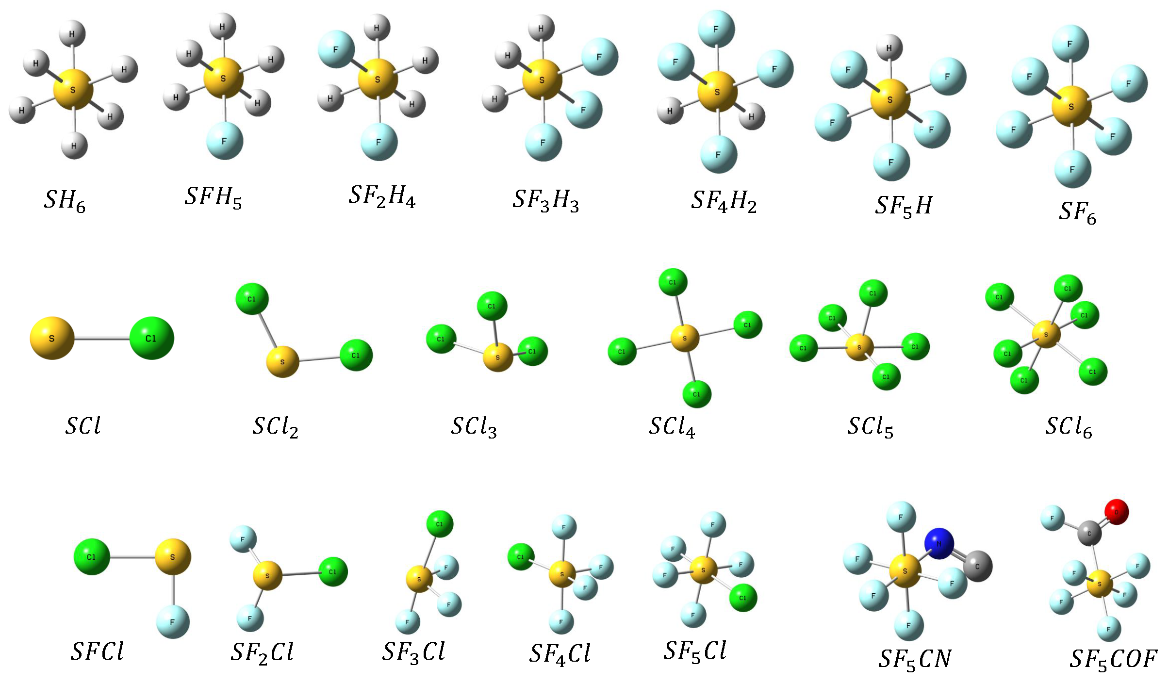
Electron and Positron Impact Ionization of SF6−nHn(n = 0 − 6); {SCln, SFn−1Cl(n = 1 − 6)} and SF5X(X = CN, CFO)

1
Department of Physics, School of Advanced Sciences, Vellore Institute of Technology University, Vellore 632014, Tamil Nadu, India
2
Institute of Plasma Technology, Korea Institute of Fusion Energy, 37 Dongjangsan-ro, Gunsan 54004, Jeollabuk-do, Republic of Korea
*
Author to whom correspondence should be addressed.
Atoms 2023, 11(10), 137; https://doi.org/10.3390/atoms11100137
Submission received: 13 September 2023 / Revised: 13 October 2023 / Accepted: 19 October 2023 / Published: 21 October 2023
(This article belongs to the Section Atomic, Molecular and Nuclear Spectroscopy and Collisions)

Abstract

:
We have calculated the electron and positron impact ionization of a set of molecules, S F 6 n H n ( n = 0 6 ) , S C l n ( n = 1 6 ) , S F n 1 C l ( n = 1 6 ) and S F 5 X ( X = C N , C F O ) , for which there are much fewer data in the literature. We have optimized the targets, and their electric polarizability is calculated along with their orbital binding and kinetic energies within the Hartree–Fock approximation that serve as input to the Binary Encounter Bethe (BEB) model for both electron and positron ionization. Most of the targets are investigated for the first time, apart from S F 6 , for which we compared our data with various experimental and theoretical data, giving us a good comparison.

1. Introduction

The collisions of electrons with atoms, molecules, ions, and surfaces are of fundamental importance in low-temperature plasmas (LTPs), with numerous applications in plasma science and technologies. SF 6 gas has many uses in industry, especially as an electrically insulating gas in high-voltage environments, and it is also used in gas-insulated voltage switchgears and gas-insulated lines [1,2]. SF 6 serves as a good dielectric in high-voltage industrial applications like power transmission and is used as a feedstock gas in the semiconductor industry for etching purposes. A mixture of SF 6 with tetrafluoroethane ( C 2 H 2 F 4 ) and other gaseous refrigerants such as R134a are being used in resistive plate chambers in neutrino and dark matter detectors and also in photosensitive gaseous detectors [3]. Despite having many applications in the plasma industry, one major drawback of SF 6 is its higher global warming potential (GWP), which is 22,800 times larger than that of C O 2 , and it is tough to decompose in the atmosphere [4]. It is found that for every gram of SF 6 gas released into the atmosphere, the hazard it causes is equivalent to every 22.5 kg of C O 2 gas [5]. Moreover, owing to the Kyoto protocol’s [6] requirement for the reduced emission of perfluorocarbons and SF 6 , research is being conducted on new gases with a lower GWP that can be suitable substitutes for existing plasma gases. Numerous scattering studies have been conducted on several perfluorocarbons (PFCs), perfluoroketons (PFKs), and perfluoronitriles (PFNs) that could be potential alternatives to or replacements for SF 6 [7,8,9]. A recent review article also highlighted the possible replacement gases for SF 6 [10]. Any substitute for the SF 6 must posses a low GWP, high dielectric strength, good thermal stability, and lower ozone-depleting potential (ODP) [11,12], and should also have a lower electron attachment cross-sections [13]. It should be noted here that most of the targets investigated contain fluorine as one of the constituent atoms, which could indirectly damage the ozone layer. As there are no studies of GWP and ODP for the targets investigated here, one can also look into these properties in future studies. Rejoub et al. [14] experimentally investigated the electron impact dissociative ionization of S F x + ( x = 1 6 ) and F + using a time-of-flight (TOF) mass spectrometer with a position-sensitive detector (PSD) from first ionization energy until 1000 eV, in which the partial ionization cross-sections (PICS) were summed up to give total ionization cross-sections (TICS). Bull et al. [15,16] also experimentally provided the PICS of the fragment cations of SF 6 , and the sum of the PICS gives the TICS of the parent molecule, SF 6 . Antony and coworkers employed the spherical complex optical potential (SCOP) and complex scattering potential-ionization contribution (CSP-ic) [17] methods to calculate electron impact TICS for SF 6 [18] and several other similar molecules, including S F n ( n = 1 5 ) [19,20]. They also presented a review article on positron scattering on atoms and molecules [21]. The National Institute of Standards and Technology (NIST) web book contains electron impact BEB TICS for molecules such as S F n ( n = 1 6 ) and many more atoms and molecules [22]. The Deutsch-Märk (DM) model [23,24] is another method that is used to calculate the electron impact TICS for atomic and molecular targets. Jain and Khare [25,26] also provided a model to study electron scattering on atoms, molecules, and clusters. Zhang et al. proposed a new method of combining the BEB model and the DM model to predict the TICS that give close agreement with the experimental results [8]. Also, Bartschat et al. showed [27] a way to calculate electron impact ionization cross-sections using the R-matrix method for atoms, which is computationally expensive. In this work, we have used the BEB model, where no fitting parameters are used to calculate electron impact TICS, which was originally formulated by Kim et al. [28]; for positron impact TICS, we used the various modified BEB models formulated by Fedus et al. [29] and Franz et al. [30]. In recent years, the BEB method has been very successful in calculating TICS for various molecules ranging from diatomic [31] to organic molecules [32], with applications in plasma and biological sciences.
Here, we present the total electron/positron impact TICS for the following set of molecular targets: S F 6 n H n ( n = 0 6 ) , ( S C l n , S F n 1 C l ) : ( n = 1 6 ) , and S F 5 C N , S F 5 C F O . There are no studies available for ionization for these molecular targets, and they could be viable replacements for SF 6 in plasma application. Yu et al. [33] studied the dielectric strength and boiling point of S F 6 n H n ( n = 0 6 ) , S F 5 C N , S F 5 C F O . Leiding et al. performed quantum chemical studies on bonding and isomerism on S C l n , S F n 1 C l ( n = 1 6 ) [34,35]. The literature survey indicates a lack of TICS for these targets, which has motivated us to take up this study to provide the TICS for both electron and positron impacts. The optimized structures of the molecular targets studied are presented in Figure 1. In the sections to follow, we describe the methodology in Section 2, present the results and discussion in Section 3, and conclude our findings in Section 4.

2. Binary Encounter Bethe (BEB) Model

The BEB model [28] is one of the standard approaches for determining the TICS for atoms, molecules, and ions. The BEB method calculates the electron impact TICS for each orbital, and the sum of the cross-sections for each orbital in index ( i ) gives the TICS for a target under consideration.
σ ( E ) = i N σ i ( E ) ,
The BEB method can also be used to model the direct positron impact ionization of atoms and molecules with the Binary Encounter Dipole (BED) model combined with the Wannier-type threshold law [36] to give a simple analytical formula for ionization [29,30]. The BEB model is the simplified version of the BED [28] model. The difference between the two models is the exclusion of the differential dipole oscillator strengths (DOS), which is required for each molecular orbital of the target atom or molecule in the BED model. There are also several other versions of the BEB model to calculate the single differential cross-section [37,38,39] and a modified version of the BEB model which also accounts for the relativistic effects [40,41]. But, here, we have employed the simplified BEB model, which does not require values of continuum DOS, d f d W . The BEB formula for the determination of the TICS is as follows:
σ i B E B ( E ) = S ( t i + u i + 1 ) / n Q i ln t i 2 1 1 t i 2 + ( 2 Q i ) 1 1 t i ln t i t i + 1
The reduced variables t i , u i , Q i and S are as follows:
S = 4 π a 0 2 N ( R / B ) 2 , u i = U / B , t i = E / B
Q i = 2 N B B + W d f d W d W
Here, n is the principal quantum number, W is the ejected electron’s kinetic energy, and Q i is the dipole constant defined in terms of DOS. When we lack the information on d f d W , then we can assume Q i = 1 for the simplified BEB model. The incident kinetic energy is ( E ) , the Bohr radius is ( a 0 = 0.52918 A ˚ ) , and the Rydberg constant is ( R = 13.6057 eV ) . The orbital binding energy is ( B ) , the orbital kinetic energies are ( U ) , and the orbital occupation number is ( N ) . To calculate the orbital parameters required as input to the BEB method, we first optimized the target molecules using the density functional theory (DFT) with the functional ω B 97 X D with the aug-cc-PVTZ basis set, which calculates the energy minima at which the molecule is more stable. After optimization, the orbital binding and kinetic energies are calculated using the Hartree–Fock (HF)-type approximation. The magnitudes of BEB TICS calculated using the parameters obtained by means of DFT functionals tend to be higher than the experimental TICS [7]; hence, they are not utilized in our present study. The BEB TICS calculated using the orbital parameters obtained from the HF approximation seem reasonable and are found to give cross-section values within the uncertainty of 10–15% of the experimental values of TICS [42]. All the quantum chemistry calculations are performed using the Gaussian-16 [43] quantum chemistry package.
The BEB model for direct positron impact ionization is given by Fedus et al. [29], who modified the analytical BEB model for electrons of Kim et al. [28]. The BEB model introduced by Fedus et al. [29] for positron impact are called B E B 0 and B E B W models. The equation where there is no effect of the scaling term, i.e., C = 0 , from which it got the name B E B 0 , is given in Equation (3):
σ i B E B 0 ( E ) = S i t i + u i + 1 ln t i 2 1 1 t i 2 + 1 1 t i ,
In the B E B W model, a scaling factor ( f i W ) is incorporated that controls how the cross-section behaves at energies that are just above the ionization threshold and guarantees that the cross-section obeys the Wannier law σ ( E ) ( E B ) 1.127 . Hence, this model is called the B E B W model, and is given below:
σ i B E B W ( E ) = S i t i + u i + 1 + f i W ln t i 2 1 1 t i 2 + 1 1 t i ,
the scaling factor is defined as
f i W = C ν k ,
where ν = ( t i 1 ) and the power term k is 1.65, which obeys the Wannier exponent law proposed by Klar [36]. As the value of C is an unknown parameter, for simplicity, the constant C is fixed to be equal to unity, which also aligns well with the experimental data.
The BEB model for positron impact was further extended by Franz et al. [30] with the implementation of two new variants of the BEB model. The two new models introduced by Franz et al. [30] are called the B E B A and B E B B models, which implement the Jansen’s threshold law [44] and are modified versions of the B E B 0 model as given below:
σ i B E B A ( E ) = S i t i + u i + 1 + f i A ln t i 2 1 1 t i 2 + 1 1 t i ,
where the scaling factor is defined as
f i A = C ν α 1 η ,
Here,
η = e β i ν ,
the value of α and β are fixed by Franz et al. [30],
α = 2.640 ,
β i = 0.489 B i 2 R ,
and the value of C is fixed to be equal to unity. The factor β i depends on the orbital binding energy. This is due to the use of the reduced kinetic energy ( t i ) in the BEB model rather than the excess kinetic energy ( Δ E = E B i ) as in the threshold law formulation.
The B E B B model of Franz et al. [30] is given below:
σ i B E B B ( E ) = S i t i + u i + 1 ln t i 2 1 1 t i 2 + h i ( t i ) 1 1 t i + g i ( t i ) 1 1 t i α ,
where the terms g i ( t i ) and h i ( t i ) are defined as
g i ( t i ) = C i η ,
h i ( t i ) = 1 g i ( t i ) ,
It has been verified that the product of g i ( t i ) and h i ( t i ) gives Jansen’s threshold law [44]. At high incident energies, a more dominant behavior of the second term is seen, which brings the cross-section to the maximum. Franz et al. [30] have found that for polar molecules, the B E B ( 0 / W ) model is reliable, and for non-polar molecules, both B E B ( A / B ) are in good agreement with the experimental data. Hence, the scope for the development of a more generalized model for positron impact ionization, which can predict the cross-section for any molecule irrespective of their polar or non-polar nature, could be looked at in the near future.

3. Results

In this section, we present the numerical values of the maximum TICS for electron and positron impact in the tabular form along with the calculated polarizability and highest occupied molecular orbital (HOMO) energy for all the targets. Our calculated values are compared with the literature data and are shown in Table 1. The present HOMO energy computed in the HF approximation is compared with the ionization potential (IP) of the target available in the literature. Our values are generally higher than those of the literature data, as the HF calculations are found to predict energies that are generally higher compared to the actual IP because the effect of electron correlations are not taken into account. The polarizability calculated in the HF approximation with the aug-cc-PVTZ basis set is also provided in Table 1. Our polarizability for S F 6 n H n ( n = 0 6 ) compares fairly well with the data of Yu et al. [33]. For other sets S C l n , S F n 1 C l ( n = 1 6 ) and S F 5 C N , S F 5 C F O , we could not find any comparison of the polarizability in the literature. Here, we also present the graphical representation of the TICS for the various sets of molecules investigated in this study for both electron and positron ionization. In Figure 2, we have shown the comparison of our electron impact TICS data of SF 6 with those of Bull et al. [16] and Rejoub et al. [14]; reference BEB data from the NIST Web book [22], Joshipura et al. [18], and Zhong et al. [8]; and the recommended data of Christophorou et al. [45]. Our results for electron impact ionization show good comparison with the NIST data [22] and Rejoub et al. [14] and Christophorou et al. [45] and lie close to the experimental values with 5% and 8% uncertainty in the TICS data of Bull et al. [16] and Rejoub et al. [14]. We have also shown the positron TICS computed using various models in the same plot, as we were not able to find any comparison for the same. Since SF 6 has a zero dipole moment, it is a non-polar molecule, and we recommend using the BEB-B model to predict the TICS, as it is found to match very well with the experimental results [29,30]. The good comparison of our electron impact ionization of SF 6 has inspired us to study the set of targets S F 6 n H n ( n = 0 6 ) , S C l n , S F n 1 C l ( n = 1 6 ) and S F 5 C N , S F 5 C F O , for which we could not find a complete set of data in the literature for both electron and positron impacts.
In Figure 3, we compare the TICS of all the molecules in the set of S F 6 n H n ( n = 0 6 ) for electron and positron ionization. As we can see from the plots, with the increase in the number of electrons in the target, the TICS are also increasing. However, for S H 6 , we can see that its cross-section is larger than S H 5 F and S H 4 F 2 , owing to its lower HOMO energy, as can be seen in Table 1. Since the BEB method is very sensitive to the binding energies of the valence shell orbitals, its effect is quite prominent, where the lower binding energies lead to a higher magnitude of TICS. In Figure 3b, we have shown the positron TICS for all the targets. For S X 6 ( X = H , F ) molecules with zero dipole moment, the cross-section is calculated using the BEB-B model, and for the other molecular targets which had a nonzero dipole moment, we used the BEB-W model to calculate their positron impact TICS. There are no previous studies for these targets, and hence all the results are plotted together to obtain an idea about the shape and magnitude of the cross sections.
We have calculated the electron and positron TICS for S C l n ( n = 1 6 ) , and they are shown in Figure 4. For both electron and positron impacts, as the size of the target increases, the cross-section also increases. In this case also for non-polar molecules, such as S C l n ( n = 4 , 6 ) , the cross-sections calculated using the BEB-B model are shown, and for polar molecules such as S C l n ( n = 1 , 2 , 3 , 5 ) , the cross-sections calculated using BEB-W are plotted. Further investigation is required, as there are no data available in the literature for these targets.
Similarly, we have calculated the TICS for another set of molecules S F n 1 C l ( n = 1 6 ) that shows a similar behavior to previous cases, where the cross-section increases with the size of the target (number of electrons present in the target), as shown in Figure 5. For positron impact, the BEB-W model is used, as all the targets in this set are polar, and the results are shown in Figure 5b.
Two more targets, S F 5 C N and S F 5 C F O , that are important for plasma applications are investigated for ionization, and the results are shown in Figure 6 for electron and positron impacts. The BEB-W model is used for the calculation of positron impact TICS for these targets, as they are polar in nature.
In Figure 7, we show the comparison of the TICS for S C l 6 , S F 6 , and S H 6 in one plot for both electron and positron impacts. As the size of the S C l 6 is quite big, its cross-section is higher than the other two targets. However, the HOMO energy of S H 6 is lower than SF 6 by 7 to 8 eV; hence, the cross-sections for S H 6 and SF 6 are comparable even though the size of S H 6 is much smaller than SF 6 . Overall, the positron impact cross-sections for all the targets are larger than the electron impact due to the negation of exchange and interference effects [47] with the target, along with the inclusion of scaling factor in the Jansen’s threshold law and Wannier exponent that is used in the positron ionization.
In Figure 8, the maximum TICS for electrons and positrons are plotted with the number of electrons present for all the targets studied. For both cases, as the number of electrons increases, the maximum TICS also increase, indicated by a linear fit for all the targets.

4. Conclusions

We have calculated the electron and positron TICS for a set of molecules for which there are no or very few data available, and these molecules could be a viable alternative gas for S F 6 for plasma applications. The structures of the targets were optimized, and their electric dipole polarizability was calculated using HF approximations and compared with the available data, showing reasonable agreement. Our calculated electron TICS for S F 6 showed good comparison with various experimental and theoretical data, motivating us to perform calculations for targets for which there are no studies available for either electron or positron impacts. The electron impact ionization was calculated using the BEB model for electrons. For the positron TICS, we chose to use the BEB-W model for molecules with a zero dipole moment and the BEB-B model to calculate the cross-sections of molecules with a non-zero dipole moment. With respect to the theoretical predictions using the BEB method and in the absence of any experimental data for most of the targets, it is quite challenging to make an estimate of the uncertainty in the theoretical data. But our data could be trusted within 15% uncertainty, as the BEB TICS computed using the HF method are found to give good agreement with experimental results within an uncertainty of 15% [7,29,30,48,49,50]. We hope this study will motivate others to explore these plasma-relevant species for other collision processes along with ionization to validate our data.

Author Contributions

All the authors equally contributed in this manuscript. All authors have read and agreed to the published version of the manuscript.

Funding

This research received no external funding.

Institutional Review Board Statement

Not applicable.

Informed Consent Statement

Not applicable.

Data Availability Statement

Data will be shared upon request to the corresponding author.

Acknowledgments

S.S. acknowledges the Vellore Institute of Technology for providing a research fellowship; D.G. acknowledges the Science and Engineering Research Board (SERB), Department of Science and Technology (DST), Government of India (Grant No. SRG/2022/000394) for providing financial support and computational facilities; H.C. acknowledges support from the R&D Program of “Plasma Big Data ICT Convergence Technology Research Project (EN2342-9)” through the Republic of Korea Institute of Fusion Energy (KFE), funded by Government funds, Republic of Korea.

Conflicts of Interest

The authors declare no conflict of interest.

References

  1. Nguyen, T.T.N.; Sasaki, M.; Odaka, H.; Tsutsumi, T.; Ishikawa, K.; Hori, M. Remotely floating wire-assisted generation of high-density atmospheric pressure plasma and SF6-added plasma etching of quartz glass. J. Appl. Phys. 2019, 125, 063304. [Google Scholar] [CrossRef]
  2. Li, X.; Zhao, H.; Murphy, A.B. SF6-alternative gases for application in gas-insulated switchgear. J. Phys. D Appl. Phys. 2018, 51, 153001. [Google Scholar] [CrossRef]
  3. Matsuoka, K.; Okubo, R.; Adachi, Y. Demonstration of a 25-picosecond single-photon time resolution with gaseous photomultiplication. Nucl. Instrum. Methods Phys. Res. Sect. A Accel. Spectrometers Detect. Assoc. Equip. 2023, 1053, 168378. [Google Scholar] [CrossRef]
  4. Wang, F.; Dun, Q.; Chen, S.; Zhong, L.; Fan, X.; Li, L. Calculations of total electron impact ionization cross sections for fluoroketone and fluoronitrile. IEEE Trans. Dielectr. Electr. Insul. 2019, 26, 1693–1700. [Google Scholar] [CrossRef]
  5. Tianpeng, Y.; Dong, X.; Zhou, W.; Zheng, Y.; Ren, S.; Lei, H. Study on gas molecular structure parameters based on maximum information coefficient. IEEE Trans. Dielectr. Electr. Insul. 2022, 29, 1633–1639. [Google Scholar] [CrossRef]
  6. Oberthür, S.; Ott, H.E. The Kyoto Protocol: International Climate Policy for the 21st Century; Springer Science & Business Media: Berlin/Heidelberg, Germany, 1999. [Google Scholar]
  7. Gupta, D.; Choi, H.; Song, M.Y.; Karwasz, G.P.; Yoon, J.S. Electron impact ionization cross section studies of C2Fx (x = 1 − 6) and C3Fx (x = 1 − 8) fluorocarbon species. Eur. Phys. J. D 2017, 71, 1–10. [Google Scholar] [CrossRef]
  8. Zhong, L.; Xu, J.; Wang, X.; Rong, M. Electron-impact ionization cross sections of new SF6 replacements: A method of combining Binary-Encounter-Bethe (BEB) and Deutsch-Märk (DM) formalism. J. Appl. Phys. 2019, 126, 193302. [Google Scholar] [CrossRef]
  9. Chang, H.; Sinha, N.; Choi, H.; Song, M.Y.; Jang, H.J.; Oh, Y.H.; Song, K.D. Theoretical process for the investigation of dielectric characteristics of F3NO as an alternative gas for SF6. AIP Adv. 2023, 13, 065215. [Google Scholar] [CrossRef]
  10. Gupta, D. Brief review of electron collision studies of molecules relevant to plasma. Appl. Sci. Converg. Technol. 2020, 29, 125–132. [Google Scholar] [CrossRef]
  11. Zhong, L.; Wang, J.; Wang, X.; Rong, M. Comparison of dielectric breakdown properties for different carbon-fluoride insulating gases as SF6 alternatives. AIP Adv. 2018, 8, 085122. [Google Scholar] [CrossRef]
  12. Wang, Y.; Huang, D.; Liu, J.; Zhang, Y.; Zeng, L. Alternative environmentally friendly insulating gases for SF6. Processes 2019, 7, 216. [Google Scholar] [CrossRef]
  13. Fenzlaff, M.; Gerhard, R.; Illenberger, E. Associative and dissociative electron attachment by SF6 and SF5Cl. J. Chem. Phys. 1988, 88, 149–155. [Google Scholar] [CrossRef]
  14. Rejoub, R.; Sieglaff, D.; Lindsay, B.; Stebbings, R. Absolute partial cross sections for electron-impact ionization of SF6 from threshold to 1000 eV. J. Phys. B At. Mol. Opt. Phys. 2001, 34, 1289. [Google Scholar] [CrossRef]
  15. Bull, J.N.; Lee, J.W.; Vallance, C. Absolute electron total ionization cross-sections: Molecular analogues of DNA and RNA nucleobase and sugar constituents. Phys. Chem. Chem. Phys. 2014, 16, 10743–10752. [Google Scholar] [CrossRef]
  16. Bull, J.N.; Lee, J.W.; Vallance, C. Electron-impact-ionization dynamics of SF6. Phys. Rev. A 2017, 96, 042704. [Google Scholar] [CrossRef]
  17. Gupta, D.; Antony, B. Electron impact ionization of cycloalkanes, aldehydes, and ketones. J. Chem. Phys. 2014, 141, 054303. [Google Scholar] [CrossRef] [PubMed]
  18. Joshipura, K.; Vinodkumar, M.; Limbachiya, C.; Antony, B. Calculated total cross sections of electron-impact ionization and excitations in tetrahedral (X Y 4) and SF 6 molecules. Phys. Rev. A 2004, 69, 022705. [Google Scholar] [CrossRef]
  19. Goswami, B.; Antony, B.; Fritzsche, S. Electron impact scattering and calculated ionization cross sections for SFx (x = 1–5) radicals. Int. J. Mass Spectrom. 2017, 417, 8–15. [Google Scholar] [CrossRef]
  20. Singh, S.; Gupta, D.; Antony, B. Electron and positron scattering cross sections for propene. J. Appl. Phys. 2018, 124, 034901. [Google Scholar] [CrossRef]
  21. Nahar, S.N.; Antony, B. Positron scattering from atoms and molecules. Atoms 2020, 8, 29. [Google Scholar] [CrossRef]
  22. Linstrom, P.J.; Mallard, W.G. The NIST Chemistry WebBook: A chemical data resource on the internet. J. Chem. Eng. Data 2001, 46, 1059–1063. [Google Scholar] [CrossRef]
  23. Deutsch, H.; Märk, T.; Tarnovsky, V.; Becker, K.; Cornelissen, C.; Cespiva, L.; Bonacic-Koutecky, V. Measured and calculated absolute total cross-sections for the single ionization of CFx and NFx by electron impact. Int. J. Mass Spectrom. Ion Process. 1994, 137, 77–91. [Google Scholar] [CrossRef]
  24. Deutsch, H.; Becker, K.; Matt, S.; Märk, T. Theoretical determination of absolute electron-impact ionization cross sections of molecules. Int. J. Mass Spectrom. 2000, 197, 37–69. [Google Scholar] [CrossRef]
  25. Jain, D.; Khare, S. Ionizing collisions of electrons with CO2, CO, H2O, CH4 and NH3. J. Phys. B At. Mol. Phys. 1976, 9, 1429. [Google Scholar] [CrossRef]
  26. Khare, S.P. Introduction to the Theory of Collisions of Electrons with Atoms and Molecules; Springer Science & Business Media: New York, NY, USA, 2002. [Google Scholar]
  27. Bartschat, K.; Burke, P. The R-matrix method for electron impact ionisation. J. Phys. B At. Mol. Phys. 1987, 20, 3191. [Google Scholar] [CrossRef]
  28. Kim, Y.K.; Rudd, M.E. Binary-encounter-dipole model for electron-impact ionization. Phys. Rev. A 1994, 50, 3954. [Google Scholar] [CrossRef]
  29. Fedus, K.; Karwasz, G.P. Binary-encounter dipole model for positron-impact direct ionization. Phys. Rev. A 2019, 100, 062702. [Google Scholar] [CrossRef]
  30. Franz, M.; Wiciak-Pawłowska, K.; Franz, J. Binary-Encounter Model for Direct Ionization of Molecules by Positron-Impact. Atoms 2021, 9, 99. [Google Scholar] [CrossRef]
  31. Huber, S.E.; Mauracher, A.; Süß, D.; Sukuba, I.; Urban, J.; Borodin, D.; Probst, M. Total and partial electron impact ionization cross sections of fusion-relevant diatomic molecules. J. Chem. Phys. 2019, 150, 024306. [Google Scholar] [CrossRef]
  32. Gupta, D.; Choi, H.; Singh, S.; Modak, P.; Antony, B.; Kwon, D.C.; Song, M.Y.; Yoon, J.S. Total ionization cross section of cyclic organic molecules. J. Chem. Phys. 2019, 150, 064313. [Google Scholar] [CrossRef]
  33. Yu, X.; Hou, H.; Wang, B. Prediction on dielectric strength and boiling point of gaseous molecules for replacement of SF6. J. Comput. Chem. 2017, 38, 721–729. [Google Scholar] [CrossRef] [PubMed]
  34. Leiding, J.; Woon, D.E.; Dunning, T.H., Jr. Bonding in SCln (n = 1–6): A Quantum Chemical Study. J. Phys. Chem. A 2011, 115, 4757–4764. [Google Scholar] [CrossRef] [PubMed]
  35. Leiding, J.; Woon, D.E.; Dunning, T.H., Jr. Bonding and Isomerism in SFn−1Cl (n = 1–6): A Quantum Chemical Study. J. Phys. Chem. A 2011, 115, 329–341. [Google Scholar] [CrossRef] [PubMed]
  36. Klar, H. Threshold ionisation of atoms by positrons. J. Phys. B At. Mol. Phys. 1981, 14, 4165. [Google Scholar] [CrossRef]
  37. Kim, Y.K.; Johnson, W.R.; Rudd, M.E. Cross sections for singly differential and total ionization of helium by electron impact. Phys. Rev. A 2000, 61, 034702. [Google Scholar] [CrossRef]
  38. Guerra, M.; Amaro, P.; Machado, J.; Santos, J. Single differential electron impact ionization cross sections in the binary-encounter-Bethe approximation for the low binding energy regime. J. Phys. B At. Mol. Opt. Phys. 2015, 48, 185202. [Google Scholar] [CrossRef]
  39. Garkoti, P.; Luthra, M.; Goswami, K.; Bharadvaja, A.; Baluja, K.L. The binary-encounter-Bethe model for computation of singly differential cross sections due to electron-impact ionization. Atoms 2022, 10, 60. [Google Scholar] [CrossRef]
  40. Kim, Y.K.; Santos, J.P.; Parente, F. Extension of the binary-encounter-dipole model to relativistic incident electrons. Phys. Rev. A 2000, 62, 052710. [Google Scholar] [CrossRef]
  41. Guerra, M.; Parente, F.; Indelicato, P.; Santos, J. Modified binary encounter Bethe model for electron-impact ionization. Int. J. Mass Spectrom. 2012, 313, 1–7. [Google Scholar] [CrossRef]
  42. Karwasz, G.P.; Możejko, P.; Song, M.Y. Electron-impact ionization of fluoromethanes–Review of experiments and binary-encounter models. Int. J. Mass Spectrom. 2014, 365, 232–237. [Google Scholar] [CrossRef]
  43. Frisch, M.; Trucks, G.; Schlegel, H.B.; Scuseria, G.; Robb, M.; Cheeseman, J.; Scalmani, G.; Barone, V.; Petersson, G.; Nakatsuji, H.; et al. Gaussian 16. 2016. Available online: https://gaussian.com/gaussian16/ (accessed on 12 September 2023).
  44. Jansen, K.; Ward, S.; Shertzer, J.; Macek, J. Absolute cross section for positron-impact ionization of hydrogen near threshold. Phys. Rev. A 2009, 79, 022704. [Google Scholar] [CrossRef]
  45. Christophorou, L.G.; Olthoff, J.K. Electron interactions with SF 6. J. Phys. Chem. Ref. Data 2000, 29, 267–330. [Google Scholar] [CrossRef]
  46. Johnson, R.D., III. Computational Chemistry Comparison and Benchmark DataBase. 2022. Available online: https://cccbdb.nist.gov/ (accessed on 12 September 2023).
  47. Blanco, F.; García, G. Interference effects in the electron and positron scattering from molecules at intermediate and high energies. Chem. Phys. Lett. 2015, 635, 321–327. [Google Scholar] [CrossRef]
  48. Hwang, W.; Kim, Y.K.; Rudd, M.E. New model for electron-impact ionization cross sections of molecules. J. Chem. Phys. 1996, 104, 2956–2966. [Google Scholar] [CrossRef]
  49. Ghosh, S.; Nixon, K.; Pires, W.; Amorim, R.; Neves, R.; Duque, H.V.; da Silva, D.; Jones, D.; Blanco, F.; Garcia, G.; et al. Electron impact ionization of 1-butanol: II. Total ionization cross sections and appearance energies. Int. J. Mass Spectrom. 2018, 430, 44–51. [Google Scholar] [CrossRef]
  50. Graves, V.; Cooper, B.; Tennyson, J. Calculated electron impact ionisation fragmentation patterns. J. Phys. B At. Mol. Opt. Phys. 2022, 54, 235203. [Google Scholar] [CrossRef]
Figure 1. Structure of the molecular targets where the different colors represent different atoms: chlorine (green), sulfur (yellow), fluorine (cyan), oxygen (red), nitrogen (navy), hydrogen (light gray), and carbon (gray).
Atoms 11 00137 g001
Figure 2. Electron and positron TICS of S F 6 , B E B 0 ( blue line for positron ) , B E B W ( orange line for positron ) , B E B A ( green line for positron ) , B E B B ( red line for positron ) , B E B ( purple line for electron ) , Christophorou et al. (dashed brown line for electron) [45], Rejoub et al. (staZr for electron) [14], Bull et al. (upright triangle forelectron) [16], NIST BEB data (dashed pink line forelectron) [22], Joshipura et al. (dashed gray line for electron) [18], Zhong et al. (dashed green line for electron) [8].
Atoms 11 00137 g002
Figure 3. Total electron/positron impact ionization cross-sections of S F 6 x H x ( x = 0 6 ) : S F 6 ( b l u e ) , S H F 5 ( o r a n g e ) , S H 2 F 4 ( g r e e n ) , S H 3 F 3 ( r e d ) , S H 4 F 2 ( p u r p l e ) , S H 5 F ( b r o w n ) , S H 6 ( p i n k ) : (a) the cross-section for electron impact ionization; (b) the cross-section for positron impact ionization.
Atoms 11 00137 g003
Figure 4. Total electron/positron impact ionization cross-sections of S C l n ( n = 1 6 ) : S C l ( b l u e ) , S C l 2 ( o r a n g e ) , S C l 3 ( g r e e n ) , S C l 4 ( r e d ) , S C l 5 ( p u r p l e ) , S C l 6 ( b r o w n ) : (a) the cross-section for electron impact ionization; (b) the cross-section for positron impact ionization.
Atoms 11 00137 g004
Figure 5. Total electron/positron impact ionization cross-sections of S F 6 n H n ( n = 1 6 ) : S C l ( b r o w n ) , S F C l ( p u r p l e ) , S F 2 C l ( r e d ) , S F 3 C l ( g r e e n ) , S F 4 C l ( o r a n g e ) , S F 5 C l ( b l u e ) : (a) the cross-section for electron impact ionization; (b) the cross-section for positron impact ionization.
Atoms 11 00137 g005
Figure 6. Total electron/positron impact ionization cross-sections of S F 5 C F O ( o r a n g e ) and S F 5 C N ( b l u e ) : (a) the cross-section for electron impact ionization; (b) the cross-section for positron impact ionization.
Atoms 11 00137 g006
Figure 7. Comparison of the total electron and positron impact ionization cross-sections of S X 6 X = H , C l , F . The solid lines represents the cross-sections calculated using the BEB model for electrons, and the dashed lines represent the cross-sections calculated using the BEB-B model for positrons.
Atoms 11 00137 g007
Figure 8. The figure contains the correlation plots for the size of the molecule in terms of electron number and maximum TICS. Subfigure (a) shows the number of electrons present vs. the maximum TICS for electron impact, and subfigure (b) shows the number of electrons present vs. the maximum TICS for positron impact.
Atoms 11 00137 g008
Table 1. The table contains the absolute values of electric dipole polarizability, ionization energy, and the maximum cross-section; we have compared the values calculated by us with the values in the literature.
MoleculePolarzability ( A ˚ ) HOMO (eV)IP (eV)TICS max ( 10 16 cm 2 )
PresentLiteraturePresentLiteratureElectronPositron
SF 6 4.0334.490 a, 4.04 b18.45015.33 c, 15.320 a, 16.5 d, 15.6 e7.4158.304
S F 5 H 4.0484.03 b16.4057.0218.264
S F 4 H 2 4.1074.07 b15.6196.6297.787
S F 3 H 3 4.2324.11 b13.4746.3107.417
S F 2 H 4 4.4464.28 b12.7046.0377.102
S F H 5 4.9024.61 b10.1986.0147.103
S H 6 5.5765.11 b9.5776.6427.078
S C l 4.96710.5079.57 a4.5225.309
S C l 2 7.32610.2529.47 a6.9128.103
S C l 3 11.39610.0898.76210.275
S C l 4 15.6929.82211.55312.777
S C l 5 16.62210.94912.98915.230
S C l 6 17.36312.21715.47517.143
S F C l 5.23513.9005.58336.534
S F 2 C l 7.27210.5216.3097.380
S F 3 C l 6.35510.6227.2168.444
S F 4 C l 6.57612.0627.7469.081
S F 5 C l 6.00412.66412.335 a8.61910.110
S F 5 C N 5.98514.2569.03710.638
S F 5 C F O 6.02614.7109.72611.433
Reference a [46] Reference b [33] Reference c [22] Reference d [45] Reference e [18].
Disclaimer/Publisher’s Note: The statements, opinions and data contained in all publications are solely those of the individual author(s) and contributor(s) and not of MDPI and/or the editor(s). MDPI and/or the editor(s) disclaim responsibility for any injury to people or property resulting from any ideas, methods, instructions or products referred to in the content.

