1. Introduction
This paper is dedicated to the memory of our colleague Professor Evgeny Denisovich Donets (1935–2021). More than 50 years ago, E.D. Donets suggested a novel design for the production of highly charged ions [
1], which later became widespread. In the device, called the electron-beam ion source (EBIS), a smooth electron beam is used for the successive ionization of atomic targets (neutral elements and low-charged ions) [
2]. An additional axial magnetic field enhances the compression of the electron beam. The highest electron current density, a prerequisite for the production of ions in high charge states, can only be achieved in the case of Brillouin focusing [
3]. The extraction of ions from the ionization region is carried out by varying the electric potentials applied to different sections of the drift tube.
In the Main Magnetic Focus Ion Source (MaMFIS), highly charged ions are produced and confined in a sequence of local ion traps, which form in crossovers (focuses of a thick magnetic lens) of the rippled electron beam [
4]. The radial confinement is due to the space charge of the electron beam and magnetic field. The axial confinement is provided by the potential well of the electron beam. Its depth
is determined by the ratio
of beam radius in its maximum and minimum cross-sections [
5]:
Here, is the accelerating voltage, is the beam perveance, I is the electron current, is the permittivity of free space, and is the absolute value of the electron charge-to-mass ratio. In a ripple-free beam (), local ion traps are not formed. In a crossover, the Brillouin limit does not apply, and the electron current density j can exceed it by orders of magnitude.
In the original MaMFIS approach, highly charged ions are extracted from local ion traps by transforming the rippled electron beam into a beam with a constant radius. The shape of the electron beam is controlled by the bias voltage on the focusing (Wehnelt) electrode, so that the local ion traps can be shifted to the electron collector region. The second way is to extract highly charged ions in the radial direction perpendicular to the electron beam by varying the potential applied to the extractor electrode [
4].
In experiments with a pilot sample of the MaMFIS, a single drift tube was integrated with the anode of the electron gun [
5]. In such a design, stationary local ion traps with a high electron current density
kA/cm
were observed. Obviously, with a certain geometry of the drift tube structure and extraction voltage, it is possible to extract highly charged ions from local ion traps using EBIS technology, i.e., by changing the electric potentials on the drift tube sections. The extraction potential should penetrate deep enough into the drift tube to open the local ion traps so that the accumulated ions could leave the electron beam along the source axis. Here, we investigate this approach in more detail.
2. Device and Electron-Optical System
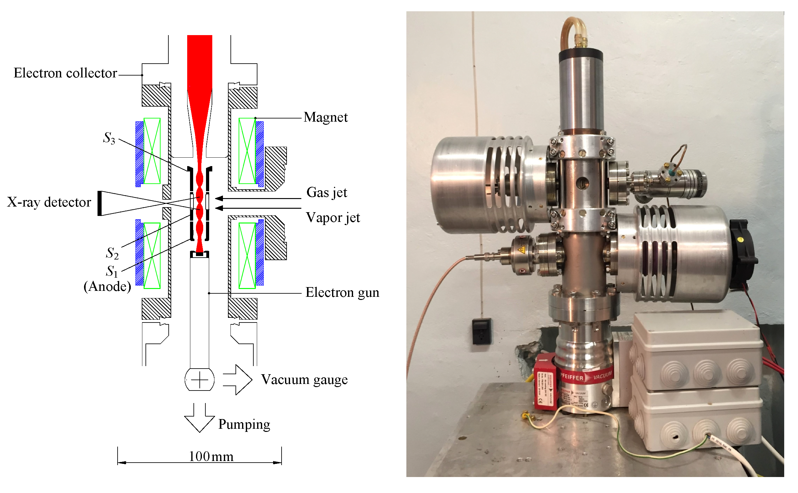
The experimental studies with MaMFIS were performed using X-ray spectroscopy in the Veksler and Baldin Laboratory of High Energy Physics at the Joint Institute for Nuclear Research in Dubna. A schematic view of the device is shown in
Figure 1. The electron beam generated by a Pierce-type gun is formed into a sequence of focuses by a thick magnetic lens. The axial magnetic field with a maximum strength of
T is created by a permanent magnet focusing system. The electron-beam current
I varied from 20 mA to 50 mA (direct current mode) at an accelerating voltage
in the range of 8–30 kV. The drift structure of the ionizer consists of three sections isolated from each other (electrodes
,
, and
in
Figure 1). The first section is integrated with the anode of the electron gun. The second section has four slots for radiation output from the source and the injection of working substances into the region of local ion traps. In the median plane of the second section, the vacuum chamber has a beryllium window of 50
m thickness and 3 mm diameter. A standard detector (Si) XR-100CR AMPTEK with a resolution of approximately 150 eV (full width at half maximum) was used in the measurements. The detector was installed opposite the Be window at a distance of 40 mm from the electron-beam axis. This configuration allows one to observe approximately 10 mm of the beam length with a sufficiently high detection efficiency. Statistics were collected during 24 h runs.
Standard vacuum technology and equipment were used to generate a high vacuum. A typical basic vacuum of approximately mbar can be achieved in one day. The quality of the vacuum is measured by a vacuum gauge mounted above the pump in the region of the electron gun. Since the vacuum gauge is located at a sufficiently large distance from the area of the ion traps, the measurements of residual gas pressure in the ionization region are not very accurate.
3. Formation of Electron Beam and Local Ion Traps
According to MaMFIS technology [
4,
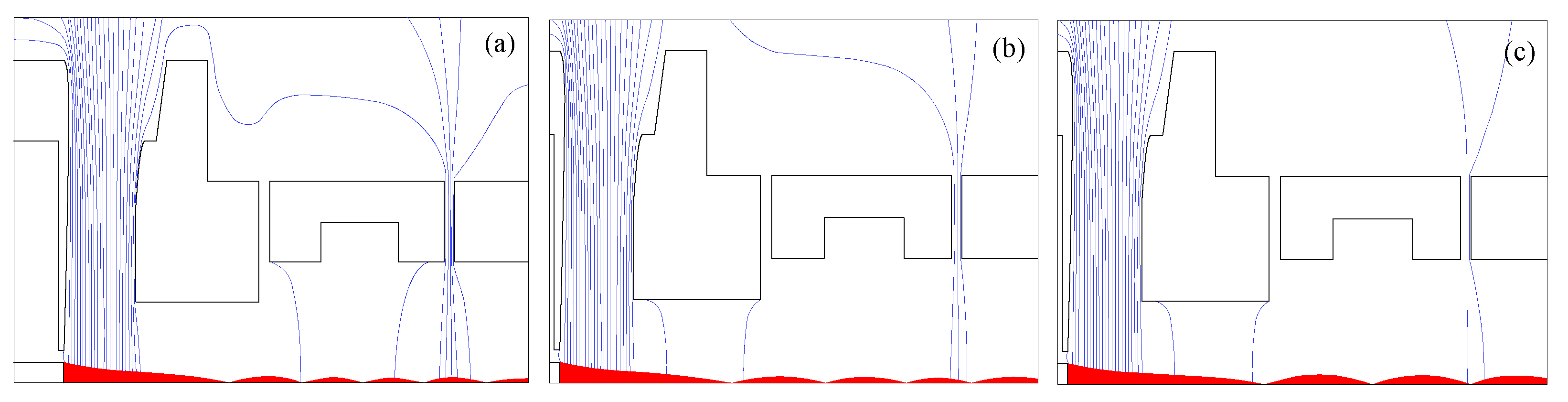
5], a rippled electron beam must be formed in the device. The focusing procedure aims to shape a crossover (or crossovers) of the electron beam with a high current density in the region of the second drift tube section. This goal can be achieved for a certain geometry of the electron gun and the corresponding distribution and magnitude of the magnetic focusing field. The magnetic lens is a thick one. In the Dubna MaMFIS, it is possible to form the third sharp focus of the electron beam in the center of the second section of the drift tube at an electron energy
E of approximately
keV and a current
I of 20 mA (
Figure 2a). In the installation, the Brillouin focusing system is applied for the electron beam in a near-zero magnetic field at the cathode without matching the electron trajectories and the magnetic focusing field (
mismatched Brillouin flow). In this case, the electron beam forms a sequence of crossovers and cathode images [
6].
The wavelength
of a ripple can be roughly estimated for a uniform magnetic field of induction
B. It reads [
3]:
where
K is the coefficient of cathode shielding. For a completely shielded cathode,
(Brillouin flow). If the cathode is unshielded from the magnetic field (
), Equation (
2) coincides with the cyclotron wavelength (pitch of the Larmor spiral). Since
is proportional to the square root of the accelerating voltage, the dependence of the crossover location (local ion trap) in the center of the middle drift tube section
on the electron-beam energy
has a discrete character for a given magnetic field. There is a set of energy values (the so-called
operating points) at which the maximum current density (crossover) of the electron beam is realized in the required location (center of the second section) (see
Figure 2). However, more precisely, the operating energy is not strictly fixed because the drift tube is of finite size: a minor deviation of
E from the operating point results in a slight shift of the focus location within the drift tube section. Under such conditions, it is still possible to detect characteristic radiation and extract highly charged ions produced at the optimal magnitude of
j in the local ion trap.
In
Figure 2a,
of the ripple wavelength
(third focus) is achieved at an electron energy
keV. The next operating point (second focus) corresponds to
of the new ripple wavelength
at another energy
. Due to Equation (
2), one can estimate the wavelength ratio as follows:
Accordingly,
should be approximately 30 keV. Numerical simulation predicts
keV (see
Figure 2c), which was confirmed in previous experiments [
7]. The next operating point (first focus) lies in the range of ~90 keV, which is impossible to implement in the present design. At an electron energy of approximately 15 keV, in the area of radiation detection, the electron beam has the maximum rippling radius and, respectively, the minimum current density (
Figure 2b). All subsequent experiments were performed at an electron-beam energy of
keV and 15 keV and a current of 20 mA.
4. Ion Extraction from the Local Trap by EBIS Technology
As we discussed in [
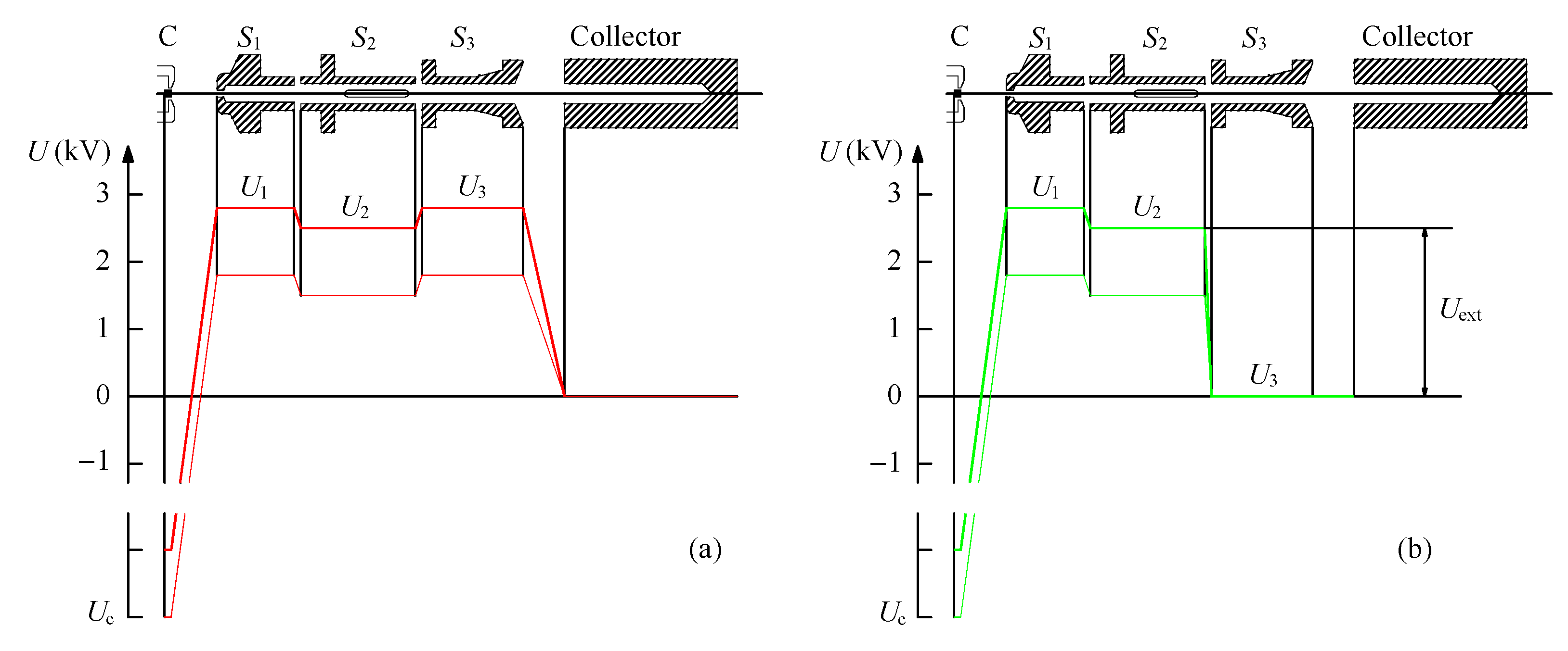
7], the extraction of highly charged ions produced and confined in local ion traps can be performed in the direction of the electron collector using EBIS technology under certain conditions, such as the diameter-to-length ratio of the drift tube, the electron trajectories and the extraction voltage (see
Figure 3).
The voltage source provides three channels for the drift tube potentials. Two channels ( and ) create constant potentials adjustable from 0 to 3 kV. In the third channel, the electric potential pulsates from a set value (3 kV at maximum) to zero. Thus, a potential difference is created between the potential applied to the second drift tube section and the zero potential; it extracts ions from the ion trap: . The duration of electric pulses and their repetition period determine the confinement (ionization) time and the duration of the ion pulse, respectively. In the experiments, the former ranged from 5 ms to 5 s.
Neglecting the minor effect of the space-charge potential of the electron beam, the accelerating voltage and thereby the incident electron energy in the ion trap region are given by the difference of potentials applied to the middle drift tube section and the cathode: . The experiments were carried out at electron energies E of keV and 15 keV. The energy of keV was achieved in two combinations; the first variant: kV and kV, while the second one: kV and kV. The extraction voltage is kV and kV, respectively.
5. Experimental Results
The characteristic radiation from the Dubna MaMFIS was detected in dependence on the confinement time for various parameters of the electron beam and the residual gas composition. The charge-state distributions of trapped ions were determined from the high-energy part of X-ray spectra corresponding to the radiative recombination of highly charged ions with beam electrons. The ionization energy is given by the difference between the energy
of emitted photons and the electron-beam energy
E, so that it can be compared to the binding energy of ionized ions. The consistency of the temporal evolutions of the experimental spectra with the theoretical simulations makes it possible to estimate the maximum electron current density achieved in the experiment [
7].
5.1. Basic Spectrum of Cathode Materials
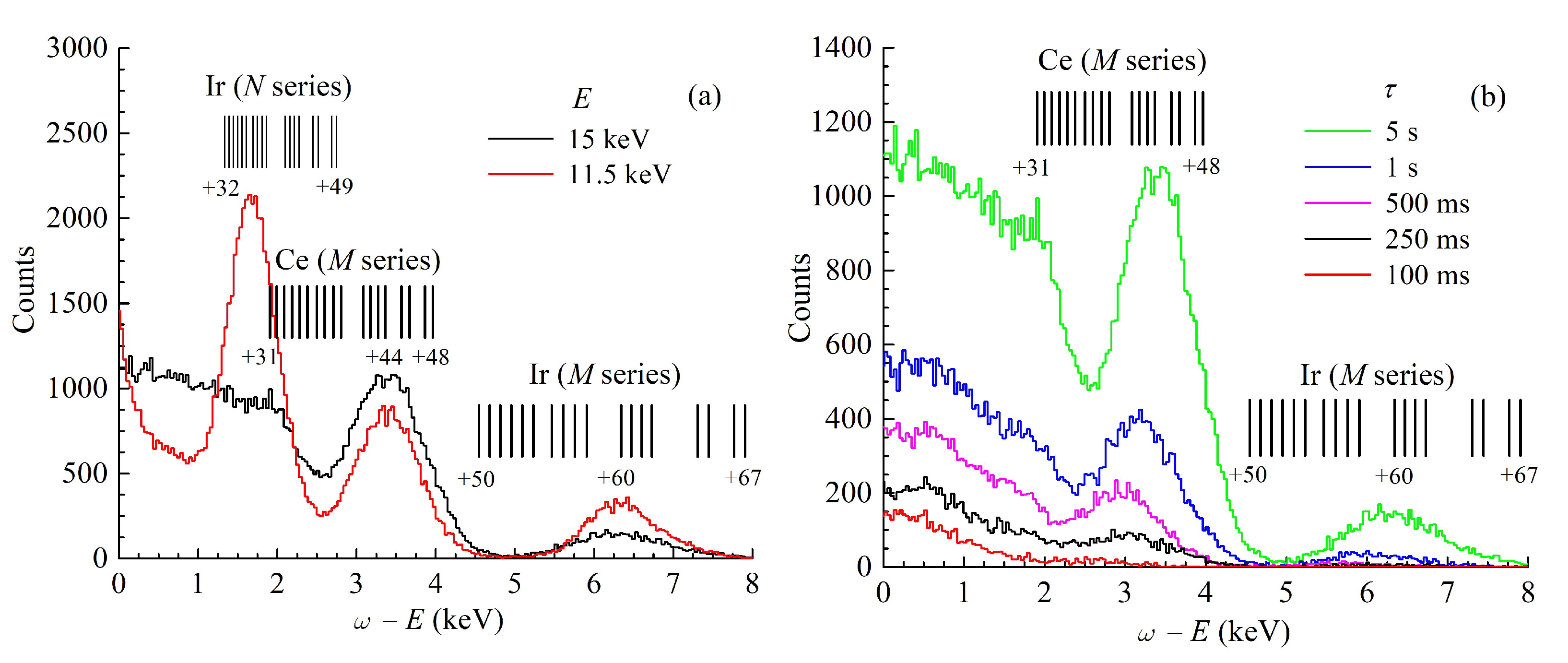
In
Figure 4a, the X-ray spectra due to the radiative recombination of highly charged ions of the cathode materials (iridium and cerium) are presented for two values of electron energy
E:
keV and 15 keV. The basic spectrum results from the radiation of a steady-state plasma that is in thermodynamic and charge equilibrium. The potential distribution along the drift tube corresponds to the ion trapping mode (see
Figure 3a). Control in time by potential
is absent. The equilibrium radiation spectrum exhibits the presence of all atomic species up to
M-shells of Ce and Ir. The resonance peak measured around the photon energy
keV for
keV corresponds to the decay of the doubly excited states of highly charged Ir ions arising from dielectronic recombination [
8].
5.2. Control over Ion Trapping
Several experiments were conducted to investigate the possibility of controlling the charge-state distributions of ions in local traps by manipulating the electric potentials applied to different drift tube sections. It corresponds to the leaky mode, in which the lower the potential barrier goes down, the larger the fraction of ions in higher charge states can be drawn from the trap.
In
Figure 4b, the temporal evolution of the radiation spectra is obtained for the following parameters:
kV,
kV, and
kV. The potential
pulsed from
kV to zero with pulse duration from
s to 5 s. The extraction voltage is
kV. The degree of ionization and the number of photon counts grow with increasing confinement time. The measurements were used together with the theoretical predictions of the two-component model described in detail in [
9] to estimate the effective electron current density
j. Computer simulations of physical processes in the ion trap under conditions close to those of the real experiment are consistent with the radiative recombination spectra shown in
Figure 4b, assuming that
j does not exceed 1 kA/cm
. The beam trajectories corresponding to this running mode are presented in
Figure 2b. The electron beam has a maximum radius profile in the transverse midplane. In the area accessible for the registration of characteristic radiation, the local ion trap is absent. The device operates according to EBIS technology.
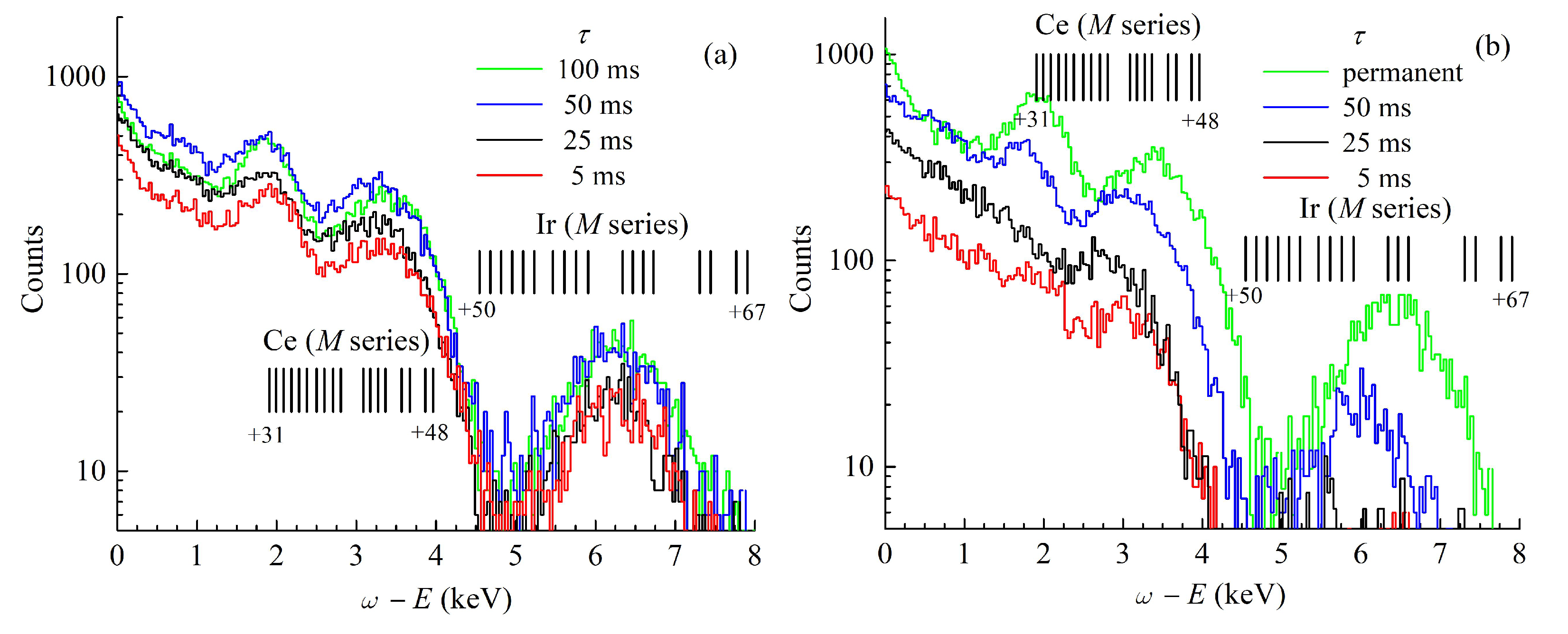
The local ion trap appears in the crossover of the electron beam at an energy
E of
keV (see
Figure 2a). In the setup, the electron energy is formed as
kV and
kV. The X-ray radiation emitted from the local trap is presented in
Figure 5. In the case of the extraction voltage
kV, the characteristic structure of the time-resolved spectra does not change (see
Figure 5a). The yield of ions in the highest charge states from the local trap is absent because the extraction voltage is not high enough. The extraction potential does not penetrate deep enough into the middle drift tube section and does not completely open the local ion trap. As can be seen from
Figure 5b, if the extraction voltage
increases to
kV, and the local ion trap is completely opened. Accordingly, it is possible to extract highly charged ions from the MaMFIS using EBIS technology.
The confinement time
of approximately 5 ms is sufficient for the ionization of the
M-shell of iridium. The radiation spectra presented in
Figure 5 are consistent with the electron current density
kA/cm
. This value should be compared to the current density
kA/cm
obtained in the electron-beam ion trap at Lawrence Livermore National Laboratory [
10]. In this case, a magnetic field of ~3 T strength was produced using the superconducting Helmholtz coils. In the EBIS, a characteristic value of the electron current density does not exceed 1 kA/cm
[
11].
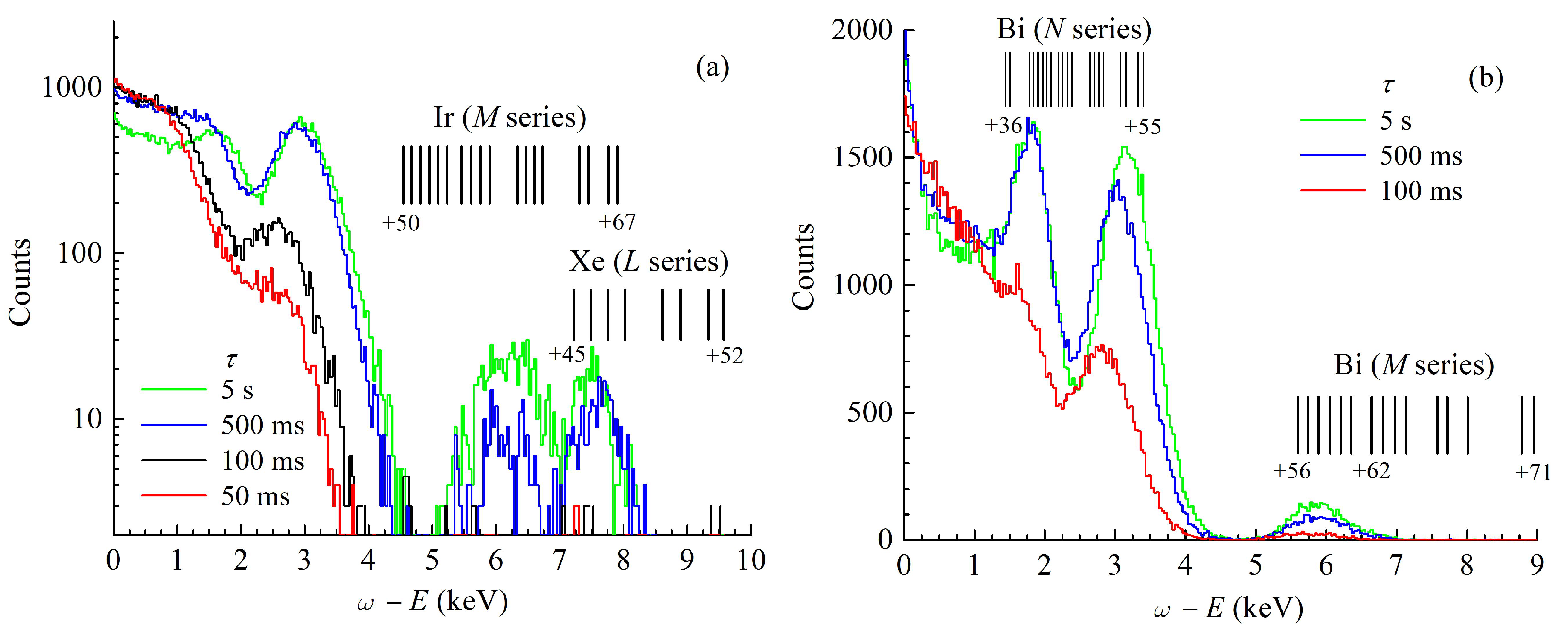
5.3. Ionization of Working Substances in the Local Ion Trap
The emission spectra were detected for injected xenon and bismuth for different durations of ion trapping (see
Figure 6). The constant pressure of the xenon in the device is (1–2)
mbar. Xenon is a cooling gas for iridium, so if the pressure of xenon is high enough, it strengthens charge-exchange processes and decreases the ionization efficiency. With the increasing confinement time, the accumulation of highly charged ions of iridium prevails in the local trap because lighter xenon is more likely to escape. Bismuth atoms were introduced into the electron beam from a small effusion cell. The highest degrees of ionization achieved in the present experiments for Xe and Bi ions are
and
, respectively.
6. Conclusions
In summary, we investigated the temporal evolution of X-ray spectra of highly charged ions produced in local ion traps following the MaMFIS technology. The highest charge states, such as Ir, Ce, Xe, and Bi, are obtained. The experimental results are consistent with the electron current density kA/cm. The time scale required for an efficient ionization of inner-shell electrons can be at the millisecond level. We also showed that, for a certain length-to-diameter drift tube ratio and particular electric potential distribution, highly charged ions can be extracted from local traps using EBIS technology. These results are of particular importance for the charge breeding of short-lived radionuclides, which can deliver low-intensity bunches of highly charged ions at a high repetition rate. Another application is the production of highly charged ions of heavy elements (e.g., for the investigation of solid surfaces).
Author Contributions
Conceptualization, V.P.O., A.V.N., A.Y.R. and A.A.L.; research, V.P.O., A.V.N., A.Y.R. and A.A.L.; writing, V.P.O. and A.V.N. All authors have read and agreed to the published version of the manuscript.
Funding
This research received no external funding.
Data Availability Statement
Not applicable.
Acknowledgments
The authors are grateful to E.E. Donets, D.E. Donets, A.Yu. Boytsov, V.V. Karpukhin, A.N. Nukin, D.O. Ponkin, D.N. Rassadov, V.V. Salnikov, A.A. Smirnov, V.I. Stegailov and S.I. Tyutyunnikov for their support of the experimental studies.
Conflicts of Interest
The authors declare no conflict of interest.
Abbreviations
The following abbreviations are used in this manuscript:
| EBIS | Electron-Beam Ion Source |
| MaMFIS | Main Magnetic Focus Ion Source |
References
- Donets, E.D. USSR Inventor’s Certificate No. 248860, 16 March (1967). Bull. OIPOTZ 1969, 24, 65. Available online: https://cir.nii.ac.jp/crid/1572261549375944704 (accessed on 30 August 2022).
- Donets, E.D. Historical review of electron beam ion sources (invited). Rev. Sci. Instrum. 1998, 69, 614–619. [Google Scholar] [CrossRef]
- Molokovsky, S.I.; Sushkov, A.D. Intense Electron and Ion Beams, 1st ed.; Springer: Berlin/Heidelberg, Germany, 2005; p. 281. [Google Scholar] [CrossRef] [Green Version]
- Ovsyannikov, V.P.; Nefiodov, A.V. Main magnetic focus ion source with the radial extraction of ions. Nucl. Instrum. Method B 2016, 367, 1–7. [Google Scholar] [CrossRef] [Green Version]
- Ovsyannikov, V.P.; Nefiodov, A.V. Main magnetic focus ion source: Basic principles, theoretical predictions and experimental confirmations. Nucl. Instrum. Method B 2016, 370, 32–41. [Google Scholar] [CrossRef]
- Amboss, K. Studies of a magnetically compressed electron beam. IEEE Trans. Electr. Dev. 1969, 16, 897–904. [Google Scholar] [CrossRef]
- Ovsyannikov, V.P.; Nefiodov, A.V.; Boytsov, A.Y.; Ramzdorf, A.Y.; Stegailov, V.I.; Tyutyunnikov, S.I.; Levin, A.A. Main magnetic focus ion source: Device with high electron current density. Nucl. Instrum. Method B 2021, 502, 23–28. [Google Scholar] [CrossRef]
- Borovik, A.; Dreiling, J.M.; Silwal, R.; Dipti; Takács, E.; Gillaspy, J.; Lomsadze, R.; Ovsyannikov, V.; Huber, K.; Schippers, S.; et al. Dielectronic resonances in highly-charged heavy ions observed in ion traps. J. Phys. Conf. Ser. 2017, 875, 052026. [Google Scholar] [CrossRef] [Green Version]
- Kalagin, I.V.; Küchler, D.; Ovsyannikov, V.P.; Zschornack, G. Modelling of ion accumulation processes in EBIS and EBIT. Plasma Sour. Sci. Technol. 1998, 7, 441–457. [Google Scholar] [CrossRef]
- Marrs, R.E. Milestones in EBIT spectroscopy and why it almost did not work. Can. J. Phys. 2008, 86, 11–18. [Google Scholar] [CrossRef]
- Zschornack, G.; Grossmann, F.; Kentsch, U.; Ovsyannikov, V.P.; Ritter, E.; Schmidt, M.; Thorn, A.; Ullmann, F. Status report of the Dresden EBIS/EBIT developments. Rev. Sci. Inst. 2010, 81, 02A512. [Google Scholar] [CrossRef] [PubMed]
| Publisher’s Note: MDPI stays neutral with regard to jurisdictional claims in published maps and institutional affiliations. |
© 2022 by the authors. Licensee MDPI, Basel, Switzerland. This article is an open access article distributed under the terms and conditions of the Creative Commons Attribution (CC BY) license (https://creativecommons.org/licenses/by/4.0/).

 ,
, 


