
Demonstration of a Compact Magneto-Optical Trap on an Unstaffed Aerial Vehicle

 , , , , , , , , and
Abstract
:
1. Introduction
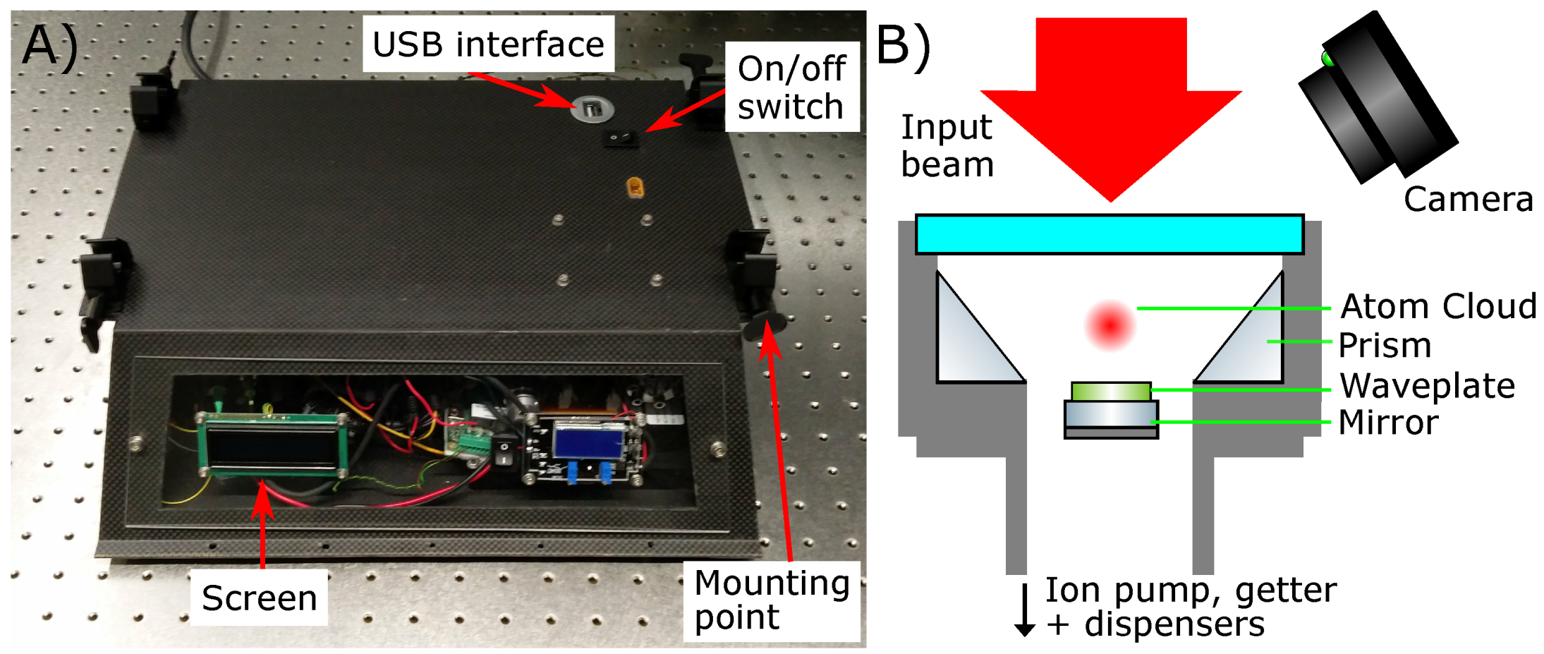
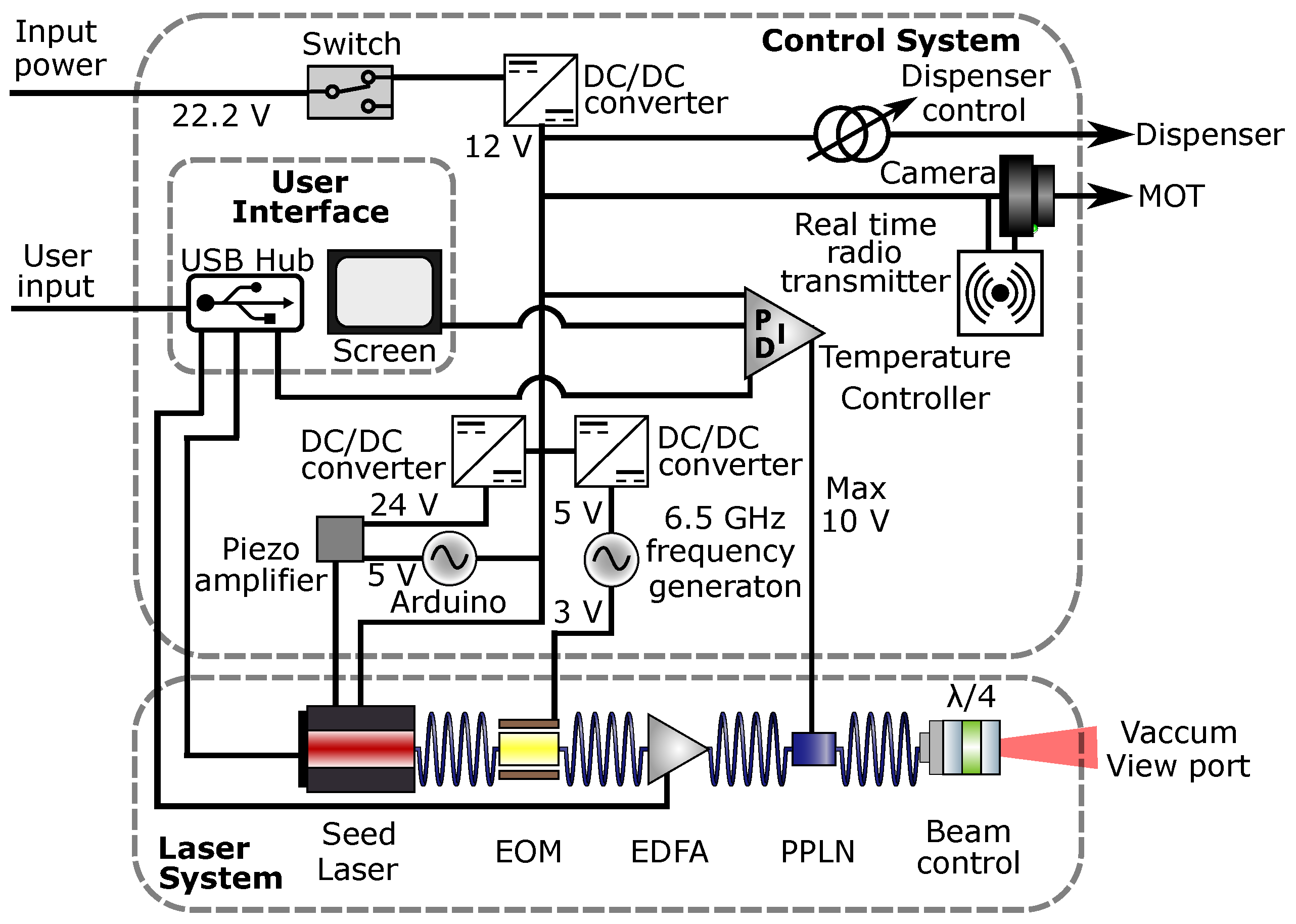
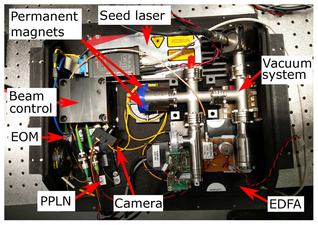
2. System Overview
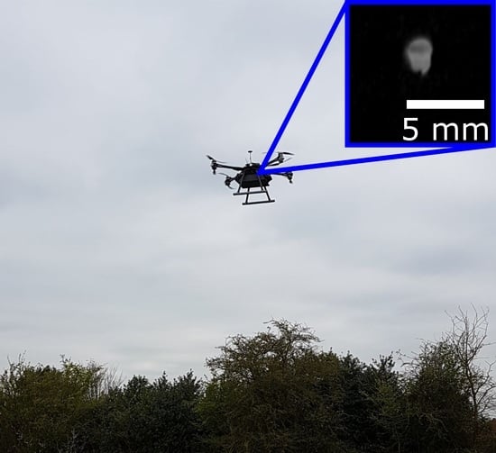
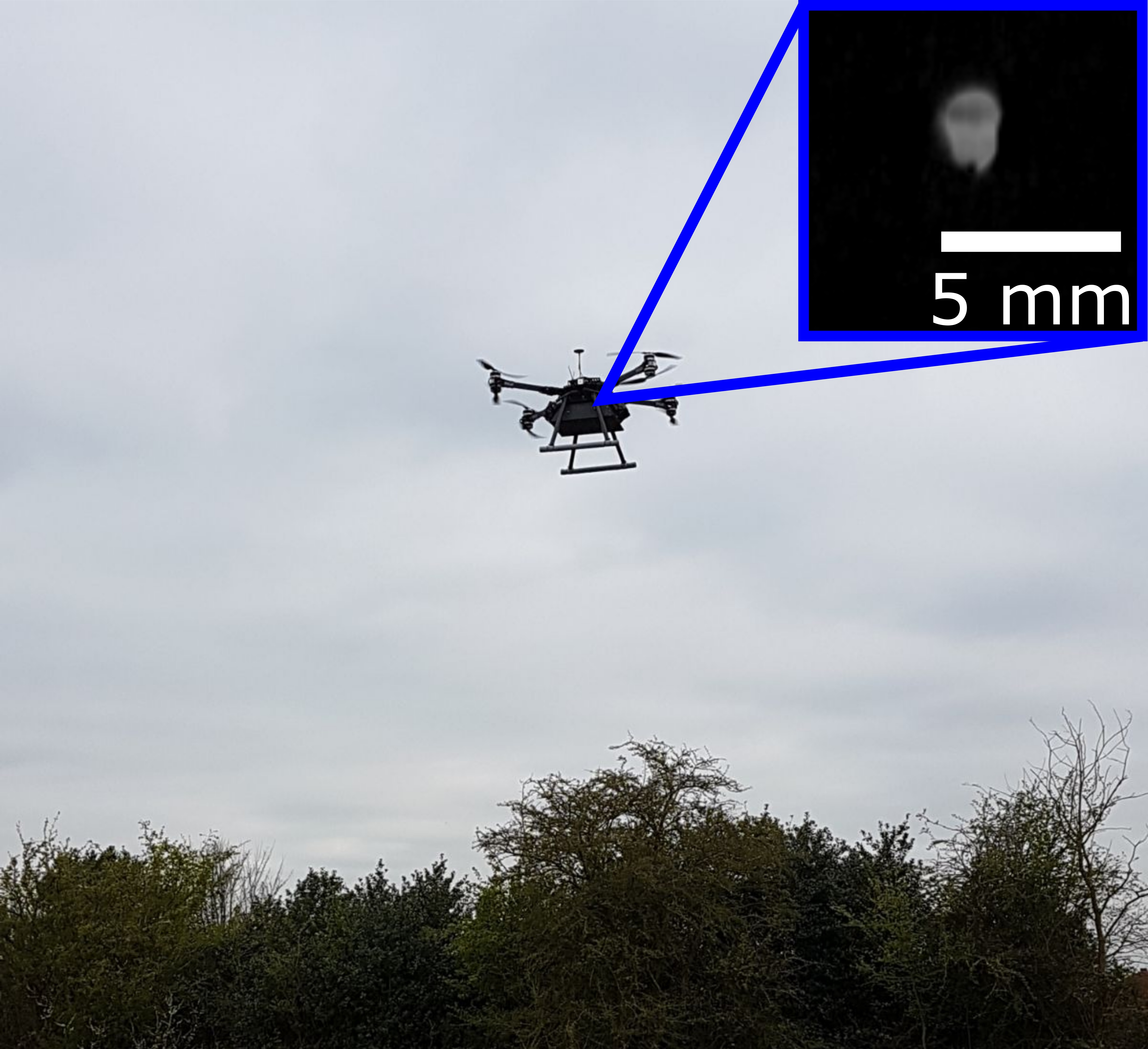
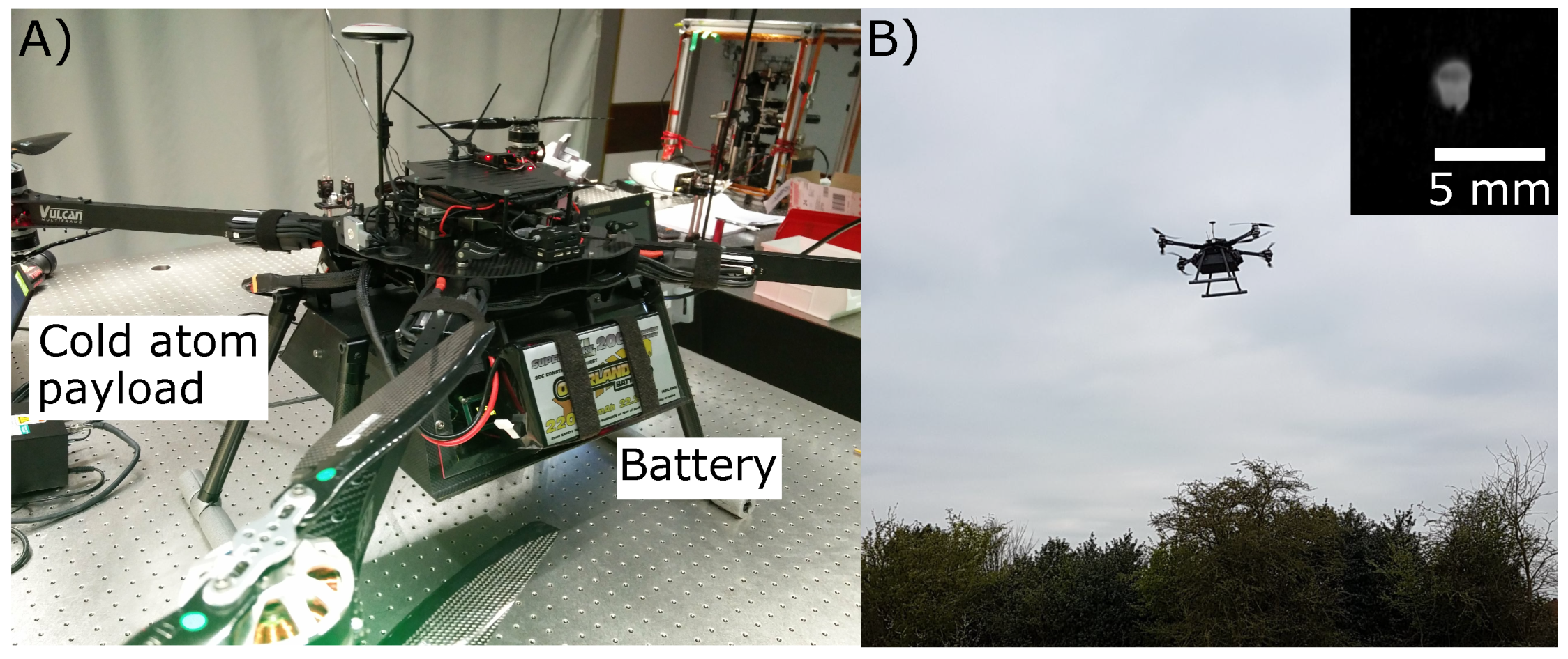
3. Test Flight
4. Discussion
Author Contributions
Funding
Institutional Review Board Statement
Informed Consent Statement
Data Availability Statement
Conflicts of Interest
Abbreviations
| EDFA | Erbium-Doped Fiber Amplifier |
| EOM | Electro-Optical Modulator |
| LiPo | Lithium Polymer |
| MOT | Magneto Optical Trap |
| PPLN | Periodically Poled Lithium Niobate |
| SWaP | Size Weight and Power |
| UAV | Unstaffed Aerial Vehicle |
References
- Kasevich, M.; Chu, S. Atomic interferometry using stimulated Raman transitions. Phys. Rev. Lett. 1991, 67, 181–184. [Google Scholar] [CrossRef] [PubMed]
- Bongs, K.; Holynski, M.; Vovrosh, J.; Bouyer, P.; Condon, G.; Rasel, E.; Schubert, C.; Schleich, W.P.; Roura, A. Taking atom interferometric quantum sensors from the laboratory to real-world applications. Nat. Rev. Phys. 2019, 1, 731–739. [Google Scholar] [CrossRef] [Green Version]
- Behbood, N.; Martin Ciurana, F.; Colangelo, G.; Napolitano, M.; Mitchell, M.W.; Sewell, R.J. Real-time vector field tracking with a cold-atom magnetometer. Appl. Phys. Lett. 2013, 102, 173504. [Google Scholar] [CrossRef] [Green Version]
- Wolf, P.; Chapelet, F.; Bize, S.; Clairon, A. Cold Atom Clock Test of Lorentz Invariance in the Matter Sector. Phys. Rev. Lett. 2006, 96, 060801. [Google Scholar] [CrossRef] [PubMed] [Green Version]
- Dickerson, S.M.; Hogan, J.M.; Sugarbaker, A.; Johnson, D.M.S.; Kasevich, M.A. Multiaxis Inertial Sensing with Long-Time Point Source Atom Interferometry. Phys. Rev. Lett. 2013, 111, 083001. [Google Scholar] [CrossRef] [PubMed] [Green Version]
- Asenbaum, P.; Overstreet, C.; Kim, M.; Curti, J.; Kasevich, M.A. Atom-Interferometric Test of the Equivalence Principle at the 10−12 Level. Phys. Rev. Lett. 2020, 125, 191101. [Google Scholar] [CrossRef]
- Fray, S.; Weitz, M. Atom-Based Test of the Equivalence Principle. Space Sci. Rev. 2009, 148, 225–232. [Google Scholar] [CrossRef] [Green Version]
- Fixler, J.B.; Foster, G.T.; McGuirk, J.M.; Kasevich, M.A. Atom Interferometer Measurement of the Newtonian Constant of Gravity. Science 2007, 315, 74–77. [Google Scholar] [CrossRef]
- Stray, B.; Lamb, A.; Kaushik, A.; Vovrosh, J.; Rodgers, A.; Winch, J.; Hayati, F.; Boddice, D.; Stabrawa, A.; Niggebaum, A.; et al. Quantum sensing for gravity cartography. Nature 2022, 602, 590–594. [Google Scholar] [CrossRef]
- Wu, X.; Pagel, Z.; Malek, B.S.; Nguyen, T.H.; Zi, F.; Scheirer, D.S.; Müller, H. Gravity surveys using a mobile atom interferometer. Sci. Adv. 2019, 5, eaax0800. [Google Scholar] [CrossRef] [Green Version]
- Carbone, D.; Antoni-Micollier, L.; Hammond, G.; de Zeeuw van Dalfsen, E.; Rivalta, E.; Bonadonna, C.; Messina, A.; Lautier-Gaud, J.; Toland, K.; Koymans, M.; et al. The NEWTON-g Gravity Imager: Toward New Paradigms for Terrain Gravimetry. Front. Earth Sci. 2020, 8, 452. [Google Scholar] [CrossRef]
- Guo, J.; Ma, S.; Zhou, C.; Liu, J.; Wang, B.; Pan, D.; Mao, A. Vibration Compensation for a Vehicle-mounted Atom Gravimeter. Preprints 2021, 2021, 110255. [Google Scholar] [CrossRef]
- Bidel, Y.; Zahzam, N.; Bresson, A.; Blanchard, C.; Cadoret, M.; Olesen, A.V.; Forsberg, R. Absolute airborne gravimetry with a cold atom sensor. J. Geod. 2020, 94, 20. [Google Scholar] [CrossRef] [Green Version]
- Geiger, R.; Ménoret, V.; Stern, G.; Zahzam, N.; Cheinet, P.; Battelier, B.; Villing, A.; Moron, F.; Lours, M.; Bidel, Y.; et al. Detecting inertial effects with airborne matter-wave interferometry. Nat. Commun. 2011, 2, 474. [Google Scholar] [CrossRef] [Green Version]
- Bidel, Y.; Zahzam, N.; Blanchard, C.; Bonnin, A.; Cadoret, M.; Bresson, A.; Rouxel, D.; Lequentrec-Lalancette, M.F. Absolute marine gravimetry with matter-wave interferometry. Nat. Commun. 2018, 9, 627. [Google Scholar] [CrossRef]
- Frye, K.; Abend, S.; Bartosch, W.; Bawamia, A.; Becker, D.; Blume, H.; Braxmaier, C.; Chiow, S.; Efremov, M.A.; Ertmer, W.; et al. The Bose-Einstein Condensate and Cold Atom Laboratory. EPJ Quantum. Technol. 2021, 8, 1. [Google Scholar] [CrossRef]
- Becker, D.; Lachmann, M.D.; Seidel, S.T.; Ahlers, H.; Dinkelaker, A.N.; Grosse, J.; Hellmig, O.; Müntinga, H.; Schkolnik, V.; Wendrich, T.; et al. Space-borne Bose–Einstein condensation for precision interferometry. Nature 2018, 562, 391–395. [Google Scholar] [CrossRef]
- Campana, S. Drones in Archaeology. State-of-the-art and Future Perspectives. Archaeol. Prospect 2017, 24, 275–296. [Google Scholar] [CrossRef]
- Rejeb, A.; Rejeb, K.; Simske, S.; Treiblmaier, H. Humanitarian Drones: A Review and Research Agenda. Internet Things 2021, 16, 100434. [Google Scholar] [CrossRef]
- Tang, L.; Shao, G. Drone remote sensing for forestry research and practices. J. For. Res. 2015, 26, 791–797. [Google Scholar] [CrossRef]
- Murrieta-Rico, F.N.; Hernandez-Balbuena, D.; Rodriguez-Quiñonez, J.C.; Petranovskii, V.; Raymond-Herrera, O.; Gurko, A.G.; Mercorelli, P.; Sergiyenko, O.; Lindner, L.; Valdez-Salas, B.; et al. Resolution improvement of accelerometers measurement for drones in agricultural applications. In Proceedings of the IECON 2016—42nd Annual Conference of the IEEE Industrial Electronics Society, Florence, Italy, 23–26 October 2016; pp. 1037–1042. [Google Scholar] [CrossRef]
- Jones, P.C.; Johnson, A.C.; von Frese, R.R.; Corr, H. Detecting rift basins in the Evans Ice Stream region of West Antarctica using airborne gravity data. Tectonophysics 2002, 347, 25–41. [Google Scholar] [CrossRef]
- Krelina, M. Quantum technology for military applications. EPJ Quantum. Technol. 2021, 8, 24. [Google Scholar] [CrossRef]
- Hinton, A.; Perea-Ortiz, M.; Winch, J.; Briggs, J.; Freer, S.; Moustoukas, D.; Powell-Gill, S.; Squire, C.; Lamb, A.; Rammeloo, C.; et al. A portable magneto-optical trap with prospects for atom interferometry in civil engineering. Philos. Trans. R. Soc. Lond. Math. Phys. Eng. Sci. 2017, 375, 20160238. [Google Scholar] [CrossRef] [Green Version]
- Lee, K.I.; Kim, J.A.; Noh, H.R.; Jhe, W. Single-beam atom trap in a pyramidal and conical hollow mirror. Opt. Lett. 1996, 21, 1177–1179. [Google Scholar] [CrossRef]
- Vovrosh, J.; Earl, L.; Thomas, H.; Winch, J.; Stray, B.; Ridley, K.; Langlois, M.; Bongs, K.; Holynski, M. Reduction of background scattered light in vacuum systems for cold atoms experiments. AIP Adv. 2020, 10, 105125. [Google Scholar] [CrossRef]
- Carraz, O.; Lienhart, F.; Charrière, R.; Cadoret, M.; Zahzam, N.; Bidel, Y.; Bresson, A. Compact and robust laser system for onboard atom interferometry. Appl. Phys. B 2009, 97, 405. [Google Scholar] [CrossRef]
- Moore, R.W.G.; Lee, L.A.; Findlay, E.A.; Torralbo-Campo, L.; Bruce, G.D.; Cassettari, D. Measurement of vacuum pressure with a magneto-optical trap: A pressure-rise method. Rev. Sci. Instrum. 2015, 86, 093108. [Google Scholar] [CrossRef] [Green Version]
- Menoret, V.; Vermeulen, P.; Moigne, N.L.; Bonvalot, S.; Bouyer, P.; Landragin, A.; Desruelle, B. Gravity measurements below 10−9 g with a transportable absolute quantum gravimeter. Sci. Rep. 2018, 8, 12300. [Google Scholar] [CrossRef]
- Theron, F.; Bidel, Y.; Dieu, E.; Zahzam, N.; Cadoret, M.; Bresson, A. Frequency-doubled telecom fiber laser for a cold atom interferometer using optical lattices. Opt. Commun. 2017, 393, 152–155. [Google Scholar] [CrossRef] [Green Version]
- Luo, Q.; Zhang, H.; Zhang, K.; Duan, X.C.; Hu, Z.K.; Chen, L.L.; Zhou, M.K. A compact laser system for a portable atom interferometry gravimeter. Rev. Sci. Instrum. 2019, 90, 043104. [Google Scholar] [CrossRef]
- Wu, X.; Zi, F.; Dudley, J.; Bilotta, R.J.; Canoza, P.; Müller, H. Multiaxis atom interferometry with a single-diode laser and a pyramidal magneto-optical trap. Optica 2017, 4, 1545–1551. [Google Scholar] [CrossRef]
- Vovrosh, J.; Voulazeris, G.; Petrov, P.G.; Zou, J.; Gaber, Y.; Benn, L.; Woolger, D.; Attallah, M.M.; Boyer, V.; Bongs, K.; et al. Additive manufacturing of magnetic shielding and ultra-high vacuum flange for cold atom sensors. Sci. Rep. 2018, 8, 2023. [Google Scholar] [CrossRef]
- Cooper, N.; Coles, L.; Everton, S.; Maskery, I.; Campion, R.; Madkhaly, S.; Morley, C.; O’Shea, J.; Evans, W.; Saint, R.; et al. Additively manufactured ultra-high vacuum chamber for portable quantum technologies. Addit. Manuf. 2021, 40, 101898. [Google Scholar] [CrossRef]
- Mohamed, A.E.M.A.; Sheridan, R.; Bongs, K.; Attallah, M.M. Microstructure-magnetic shielding development in additively manufactured Ni-Fe-Mo soft magnet alloy in the as fabricated and post-processed conditions. J. Alloys Compd. 2021, 884, 161112. [Google Scholar] [CrossRef]
- Madkhaly, S.; Coles, L.; Morley, C.; Colquhoun, C.; Fromhold, T.; Cooper, N.; Hackermüller, L. Performance-Optimized Components for Quantum Technologies via Additive Manufacturing. PRX Quantum 2021, 2, 030326. [Google Scholar] [CrossRef]
- Ravenhall, S.; Yuen, B.; Foot, C. High-flux, adjustable, compact cold-atom source. Opt. Express 2021, 29, 21143–21159. [Google Scholar] [CrossRef]
- Rushton, J.A.; Aldous, M.; Himsworth, M.D. Contributed Review: The feasibility of a fully miniaturized magneto-optical trap for portable ultracold quantum technology. Rev. Sci. Instrum. 2014, 85, 121501. [Google Scholar] [CrossRef] [Green Version]
- Burrow, O.S.; Osborn, P.F.; Boughton, E.; Mirando, F.; Burt, D.P.; Griffin, P.F.; Arnold, A.S.; Riis, E. Stand-alone vacuum cell for compact ultracold quantum technologies. Appl. Phys. Lett. 2021, 119, 124002. [Google Scholar] [CrossRef]
- Little, B.J.; Hoth, G.W.; Christensen, J.; Walker, C.; De Smet, D.J.; Biedermann, G.W.; Lee, J.; Schwindt, P.D.D. A passively pumped vacuum package sustaining cold atoms for more than 200 days. AVS Quantum Sci. 2021, 3, 035001. [Google Scholar] [CrossRef]
- Cherubini, A.; Papini, A.; Vertechy, R.; Fontana, M. Airborne Wind Energy Systems: A review of the technologies. Renew. Sust. Energ. Rev. 2015, 51, 1461–1476. [Google Scholar] [CrossRef] [Green Version]
- Feng, Y.; Zhang, C.; Baek, S.; Rawashdeh, S.; Mohammadi, A. Autonomous Landing of a UAV on a Moving Platform Using Model Predictive Control. Drones 2018, 2, 34. [Google Scholar] [CrossRef] [Green Version]
- Boaz, B. Power Line Charging Mechanism for Drones. Drones 2021, 5, 108. [Google Scholar] [CrossRef]
- Sri, K.R.B.; Aneesh, P.; Bhanu, K.; Natarajan, M. Design Analysis of Solar-Powered Unmanned Aerial Vehicle. J. Aerosp. Technol. Manag. 2016, 8, 397–407. [Google Scholar] [CrossRef]
- Grepow.com. Available online: https://www.grepow.com/page/high-voltage-battery.html (accessed on 6 December 2021).


| Subsystem | Weight (kg) | Power/Energy |
|---|---|---|
| Vacuum Chamber | 1.58 | 15.00 W |
| Magnetic field generation | 0.02 | — (6.4 W) |
| Laser and control system | 4.46 | 65.00 W |
| Housing and mounting | 0.50 | — |
| UAV | 7.40 | 3.00–15.55 kW |
| Batteries | 5.40 | 977.00 Wh |
| Total | 19.36 | 3.08–15.63 kW (3.09–15.64 kW) |
Publisher’s Note: MDPI stays neutral with regard to jurisdictional claims in published maps and institutional affiliations. |
© 2022 by the authors. Licensee MDPI, Basel, Switzerland. This article is an open access article distributed under the terms and conditions of the Creative Commons Attribution (CC BY) license (https://creativecommons.org/licenses/by/4.0/).
Share and Cite
Earl, L.; Vovrosh, J.; Wright, M.; Roberts, D.; Winch, J.; Perea-Ortiz, M.; Lamb, A.; Hayati, F.; Griffin, P.; Metje, N.; et al. Demonstration of a Compact Magneto-Optical Trap on an Unstaffed Aerial Vehicle. Atoms 2022, 10, 32. https://doi.org/10.3390/atoms10010032
Earl L, Vovrosh J, Wright M, Roberts D, Winch J, Perea-Ortiz M, Lamb A, Hayati F, Griffin P, Metje N, et al. Demonstration of a Compact Magneto-Optical Trap on an Unstaffed Aerial Vehicle. Atoms. 2022; 10(1):32. https://doi.org/10.3390/atoms10010032
Chicago/Turabian StyleEarl, Luuk, Jamie Vovrosh, Michael Wright, Daniel Roberts, Jonathan Winch, Marisa Perea-Ortiz, Andrew Lamb, Farzad Hayati, Paul Griffin, Nicole Metje, and et al. 2022. "Demonstration of a Compact Magneto-Optical Trap on an Unstaffed Aerial Vehicle" Atoms 10, no. 1: 32. https://doi.org/10.3390/atoms10010032