Article

The Casimir Effect between Parallel Plates Separated by Uniaxial Media: The Effects Due to the Orientation of the Optical Axis

School of Science, Hubei University of Technology, Wuhan 430068, China
*
Author to whom correspondence should be addressed.
Universe 2023, 9(5), 216; https://doi.org/10.3390/universe9050216
Submission received: 7 April 2023 / Revised: 22 April 2023 / Accepted: 26 April 2023 / Published: 1 May 2023
(This article belongs to the Section Field Theory)

Abstract

:
The Casimir force is calculated in the configuration of two parallel plates separated by an anisotropic media. The result exhibits a dependence on the orientation of the optical axis of the intervening media. It is possible that the Casimir force switches its direction as the optical axis orientation varies. The greatest magnitude of the force could be achieved at any optical axis orientation, depending on the dielectric properties of the plates and the intervening media. A comparison between the relativistic and nonrelativistic result revealed that the nonrelativistic approximation could significantly underestimate the attraction or overestimate the repulsion. This error was even greater when the optical axis of the intervening media was perpendicular to the surface of the plates. The nonrelativistic approximation might even fail to predict the trends of the Casimir force at small distances.

1. Introduction

The Casimir effect is one of the most significant findings of quantum filed theory. It has long been playing a vital role in various fields of science and technology [1,2,3,4,5,6].
The early research works on the Casimir effect were only focused on isotropic materials. Although the works of Parsegian [7] and Barash [8] in 1970s have already considered the anisotropy of various materials, the effects due to anisotropy did not draw much attention. It was not until the work of Munday and his colleagues [9], which calculated the Casimir torque between parallel anisotropic plates immersed in liquid, that the study of the impact of the anisotropy of materials on the Casimir effect has gained momentum. A lot of new discoveries on the Casimir force and the torque between anisotropic plates have been made in recent decades [10,11,12,13,14,15,16,17].
However, most previous studies only focused on the anisotropy of the plates and assumed the gap between the plates was a vacuum or was filled with isotropic materials, even though the media between the plates can be anisotropic as well. Liquid crystals, like 4-cyano-4-n-pentylbiphenyl (5CB), can be anisotropic [18]. Some liquid can also be anisotropic under a controlled electric field or magnetic field. In colloidal interactions, it could be completely different when using an isotropic or anisotropic host liquid [19]. In biology, the liquid between biomembranes and in vessels can be anisotropic [20,21]. Therefore, taking the anisotropy of the intervening media into account should be significant for both theoretical and applied fields. That is why, in recent years, there has been increasing interest in this field [18,22,23,24,25]. In our previous works, the exact impact of the anisotropy of the intervening media on the Casimir effect was calculated when the optical axis is perpendicular to the plates (out-of-plane case) [22,23] and when the optical axis is parallel to the plates (in-plane case) [24]. The results showed that a repulsive –attractive transition of the Casimir force could be possible in these cases, and that both the magnitude and the direction of the Casimir force could be affected by the anisotropy of the intervening media. Mostepanenko investigated the thermal Casimir force between two parallel isotropic plates separated by an anisotropic film [25]. This work and our previous works have not yet covered the effects due to the orientation of the optical axis of the intervening media. Kornilovitch calculated the van der Waals force between two parallel, identical, semi-infinite slabs separated by anisotropic 5CB liquid crystal [18]. The result showed that the van der Waals attraction is a function of the tilt angle between the optical axis and the surface normal, and it was found that the force is strongest when the optical axis is parallel to the surface normal [18]. However, this work did not completely resolve the mystery associated with the orientation of the optical axis of the intervening media. Due to the lack of reliable parameterization of the dielectric function of liquid crystals over the entire imaginary frequency, the calculation in [18] was performed in a nonrelativistic limit. Mostepanenko compared the relativistic and nonrelativistic results (out-of-plane case) and claimed that the nonrelativistic approximation could cause considerable error, even at small distances [25]. This might weaken the reliability of part of the conclusions in [18]. However, in [25], only the case when the optical axis is perpendicular to the plates was considered. Whether the nonrelativistic approximation will cause greater or smaller errors with other optical axis orientations remains unclear. Furthermore, in [18], the two parallel plates were considered to be identical, which could only result in attractive forces. The effect of the orientation of the optical axis of the intervening media associated with repulsive Casimir forces also remains unknown.
Our current study seeks to uncover more features about the effects due to the orientation of the optical axis of the intervening media on the Casimir effect. In the following sections, we are going to calculate the retarded Casimir effect between two thick isotropic plates separated by a uniaxial media. Then, we will examine the dependence of the Casimir force and energy on the orientation of the optical axis of the intervening media. More attention will be paid to cases when a repulsive force or attractive–repulsive transition is possible. We will also compare the retarded and nonretarded results with different optical axis orientations.

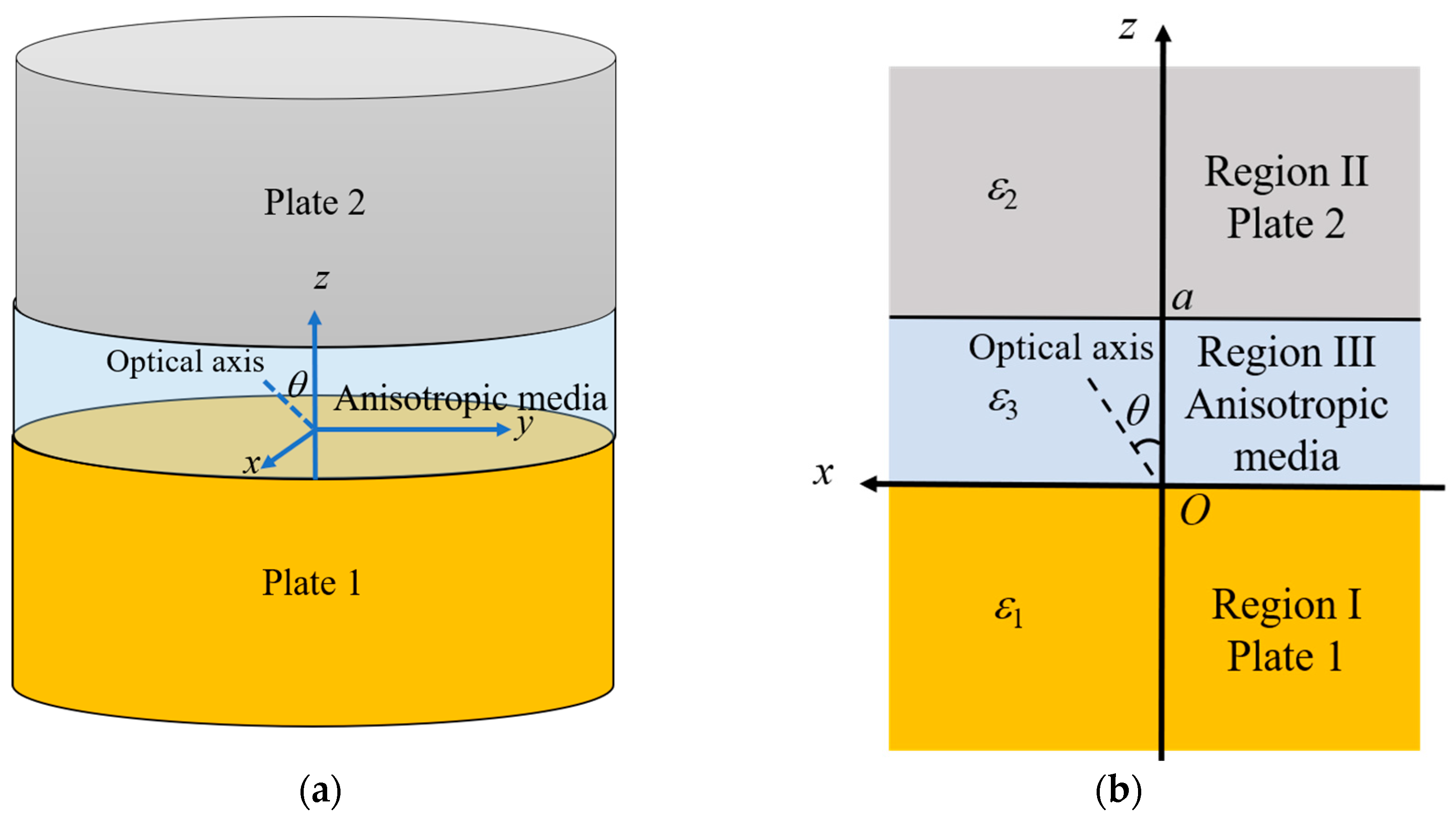
2. Casimir Energy and the Force between Parallel Slabs Separated by Uniaxial Media

In this section, we will calculate the relativistic Casimir force between two thick isotropic plates separated by a uniaxial media.
The system applied in this paper is shown in Figure 1a. It comprises two thick parallel plates separated by a third uniaxial media with a distance a. The interfaces are parallel to the x–y plane, and the z-axis is perpendicular to the interfaces. Plates 1 and 2 are assumed to be made of isotropic materials. The intervening media is uniaxial anisotropic, whose optical axis is parallel to the x–z plane with an angle θ relative to the z-axis. θ = 0 corresponds to the case when the optical axis is perpendicular to the surface of the plates (out-of-plane), while θ = π/2 corresponds to the case when the optical axis is parallel to the surface of the plates (in-plane). If we assume that the plates have infinite diameter and infinite thickness, the system could be approximately considered to be two semi-infinite plates (labeled Region I and Region II) interacting across an anisotropic media (labeled Region III) with thickness a, as shown in Figure 1b.
As we will not include magnetic material in this study, the materials in each region can be characterized by the corresponding relative dielectric permittivities. Plates 1 and 2 are made of isotropic materials, and the dielectric permittivities can be expressed in the matrix form as follows:
ε 1 = ε 1 0 0 0 ε 1 0 0 0 ε 1 ,
ε 2 = ε 2 0 0 0 ε 2 0 0 0 ε 2 ,
The intervening media is uniaxial anisotropic. Its optical axis is parallel to the x–z plane, and the angle between the optical axis and the z-axis is θ. The relative permittivity can be expressed in the matrix form as follows [9,10,11,12,18]:
ε 3 = ε 3 x x 0 ε 3 x z 0 ε 3 y y 0 ε 3 z x 0 ε 3 z z ,
with
ε 3 x x = ε 3 cos 2 θ + ε 3 sin 2 θ ε 3 z z = ε 3 cos 2 θ + ε 3 sin 2 θ ε 3 y y = ε 3 ε 3 z x = ε 3 x z = ε 3 ε 3 sin θ cos θ ,
where subscripts || and ⊥ indicate the values of permittivities in the direction parallel and perpendicular to the optical axis, respectively.
The method we used here to evaluate the Casimir energy is the surface mode method, which has been used many times in our previous work [11,12,15,16,22,23,24].
Assuming that the three regions in Figure 1b are homogenous, the electric and magnetic field with surface mode q can be expressed as
E q = i N a q e q k + a q + e q * k H q = N a q h q k + a q + h q * k ,
where N is the normalization factor, and aq and a*q are the usual creation and annihilation operators, respectively. k = (kx, ky, kz) is the wave vector.
According to the method in [11,12,15,16,22,23,24], the Casimir energy per unit area at zero temperature could be expressed as
E a , θ = 2 π c 2 1 p d p 0 ε 3 ξ 2 d ξ ln Q T E + ln Q T M ,
with
Q T E = 1 s 1 p s 2 p s 1 + p s 2 + p e x p 2 p a ξ c ε 3 ,
and
Q T M = 1 s 1 ε 1 ε 3 P s 2 ε 2 ε 3 P s 1 + ε 1 ε 3 P s 2 + ε 2 ε 3 P e x p 2 P a ξ ε 3 c ε 3 ε 3 cos 2 θ + ε 3 sin 2 θ ,
where ξ = i ω , p 2 1 = k x 2 ε 3 c 2 ξ 2 , s 1 2 = p 2 1 + ε 1 ε 3 , s 2 2 = p 2 1 + ε 2 ε 3 , and P = ε 3 cos 2 θ + ε 3 sin 2 θ ε 3 + ε 3 ε 3 p 2 1 have been introduced.
The function QTE is only associated with ε 3 and has nothing to do with ε 3 or θ, which indicates that TE modes will not be affected by the orientation of the optical axis of the intervening media. This also indicates that the orientation of the optical axis of the intervening media affects the Casimir effect by affecting only the contribution of TM modes.
The Casimir force per unit area at zero temperature will be
F a , θ = E a , θ a = 2 π 2 c 3 1 p d p 0 ε 3 3 / 2 ξ 3 d ξ p 1 Q T E Q T E + ε 3 ε 3 z z P 1 Q T M Q T M ,
If ε 3 = ε 3 = ε 3 , which means the intervening media is isotropic, Equation (9) becomes
F i s o t r o p i c a = 2 π 2 c 3 1 p 2 d p 0 ε 3 3 / 2 ξ 3 d ξ s 1 + p s 2 + p s 1 p s 2 p e x p 2 p a ξ c ε 3 1 1 + s 1 + ε 1 ε 3 p s 2 + ε 2 ε 3 p s 1 ε 1 ε 3 p s 2 ε 2 ε 3 p e x p 2 p a ξ c ε 3 1 1 ,
which is equivalent to Lifshitz’s result.

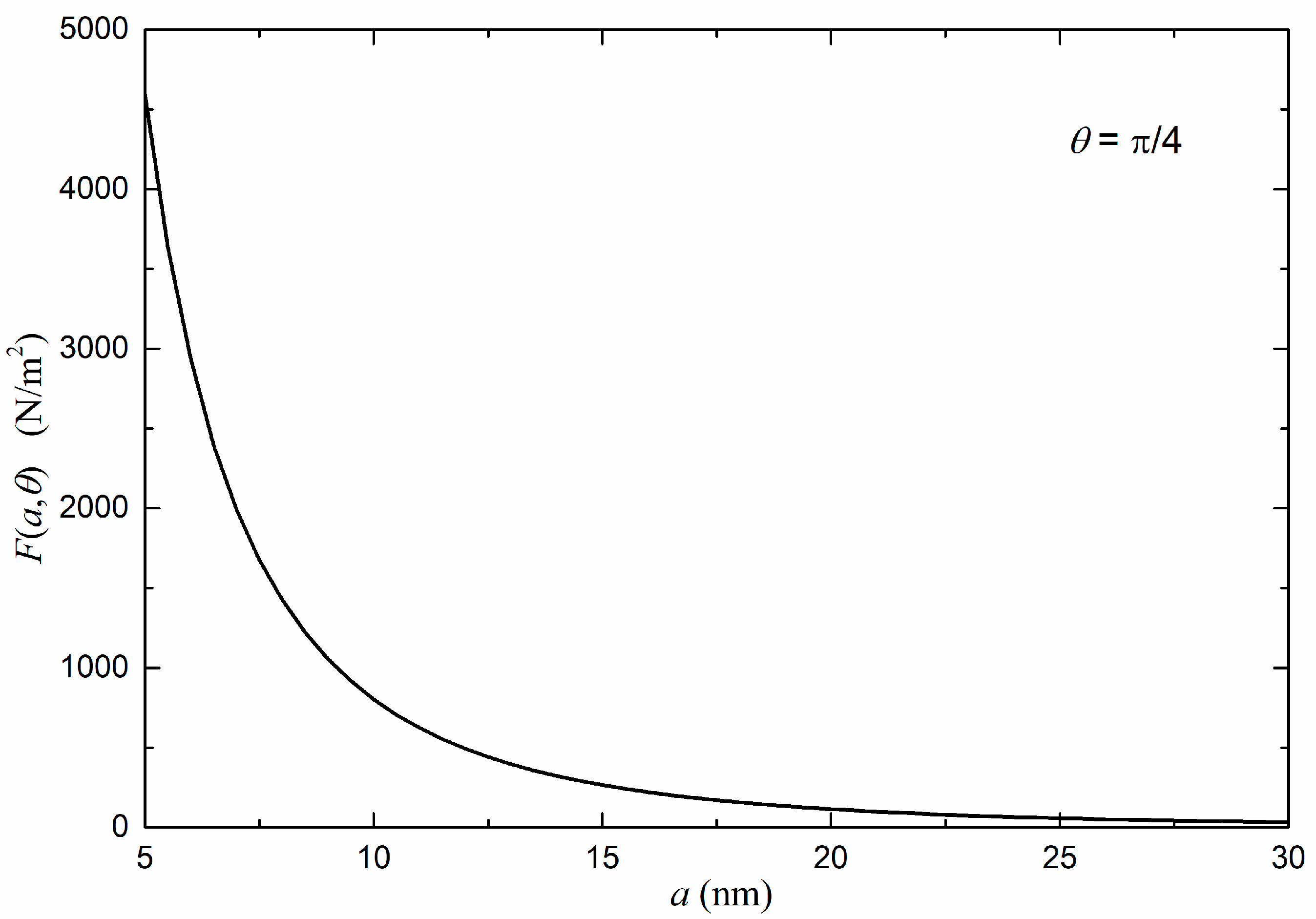
3. The Impact of the Orientation of the Optical Axis of the Intervening Media on the Casimir Force

According to Lifshitz’s theorem, the Casimir force can be repulsive when the permittivities satisfy the inequality ε1 > ε3 > ε2 (or ε1 < ε3 < ε2) [4]. If the intervening media is anisotropic, to make the repulsion possible, both ε3⊥ and ε3|| should be between ε1 and ε2, according to our previous studies [22,23,24].
In this section, we will numerically calculate the Casimir force and study the features due to different orientations of the optical axis of the intervening media. In our numerical results, a negative force corresponds to an attraction, while a positive force corresponds to a repulsion. We will discuss two cases: case 1: the intervening media is positive (ε3|| > ε3⊥); case 2: the intervening media is negative (ε3|| < ε3⊥).

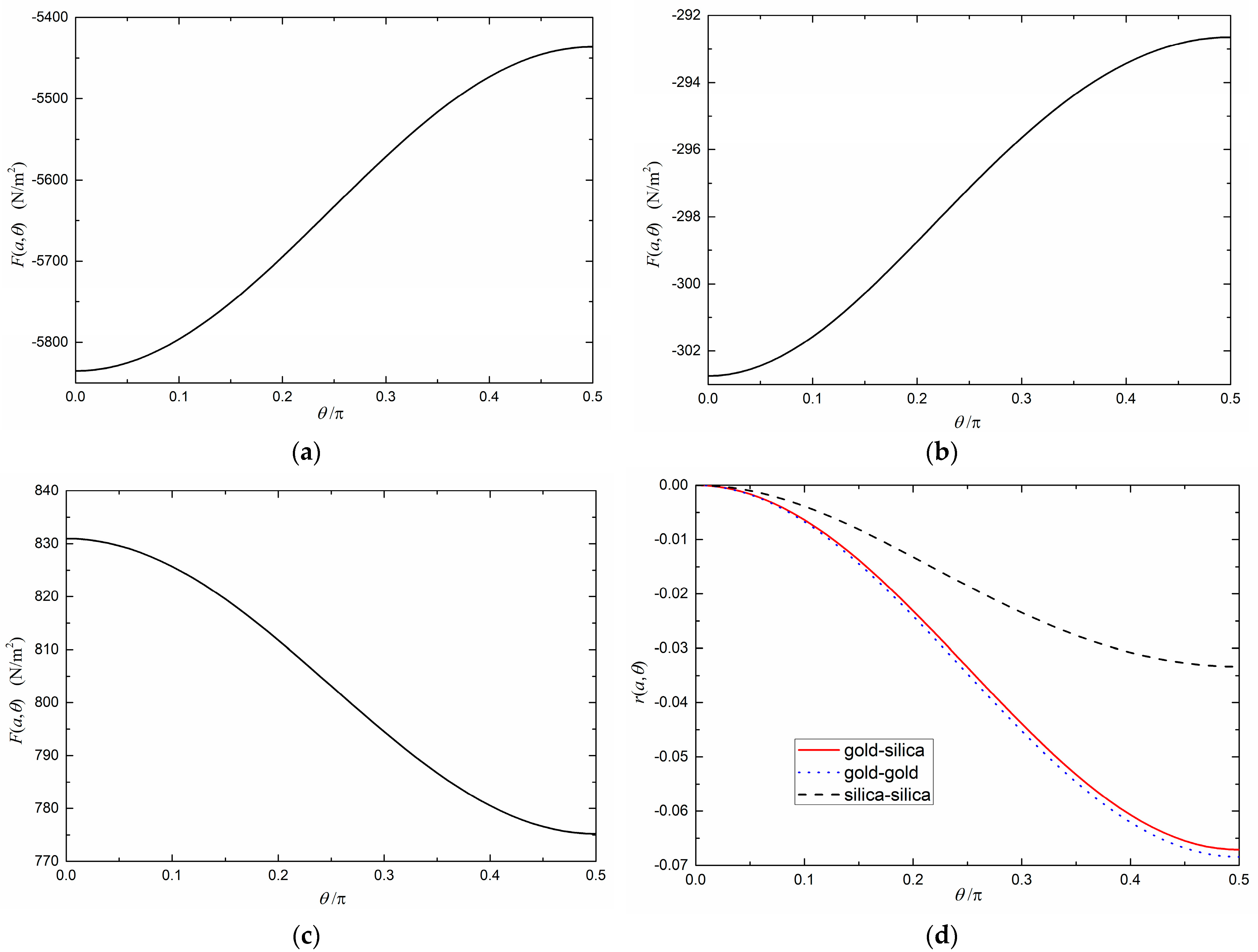
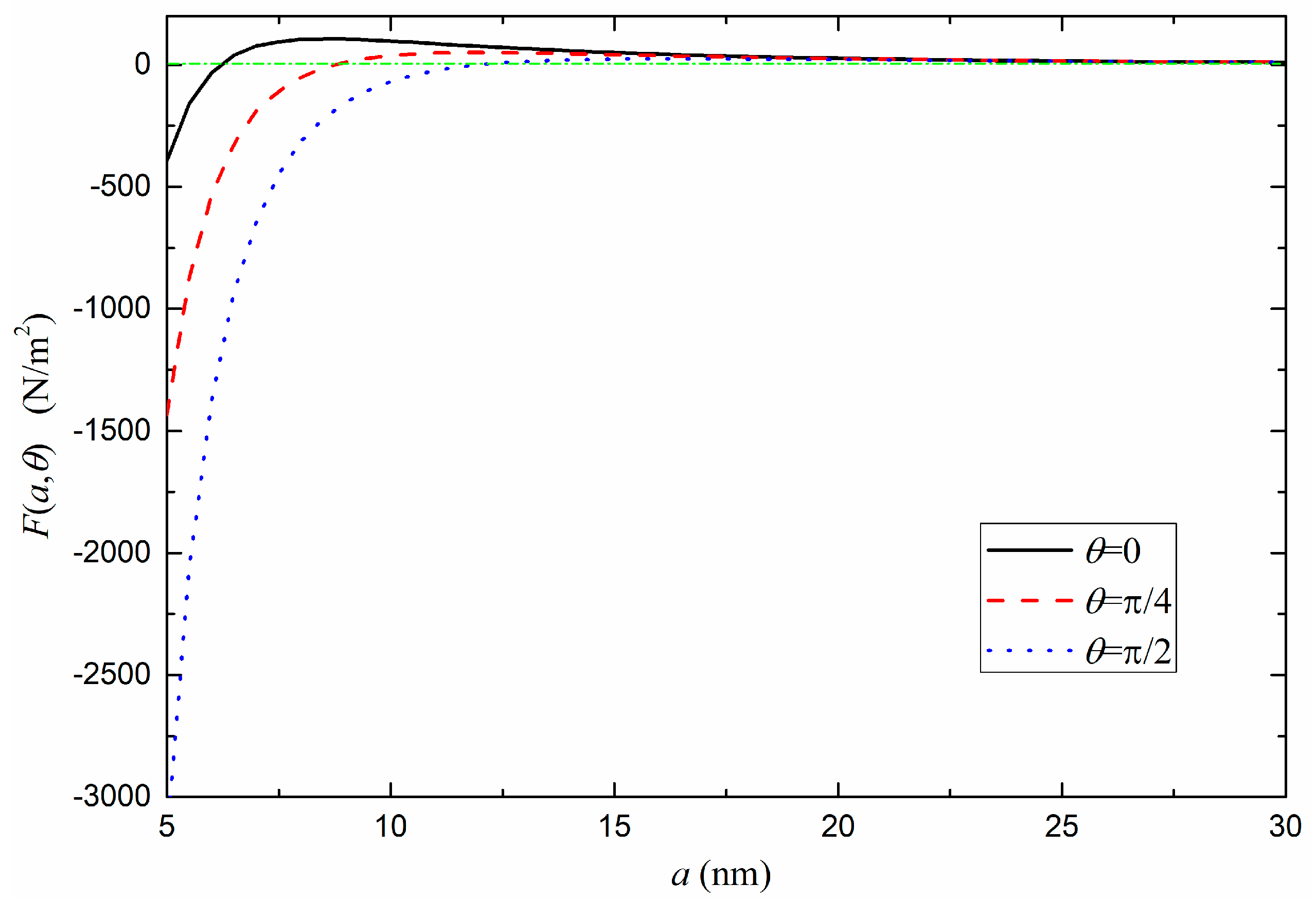
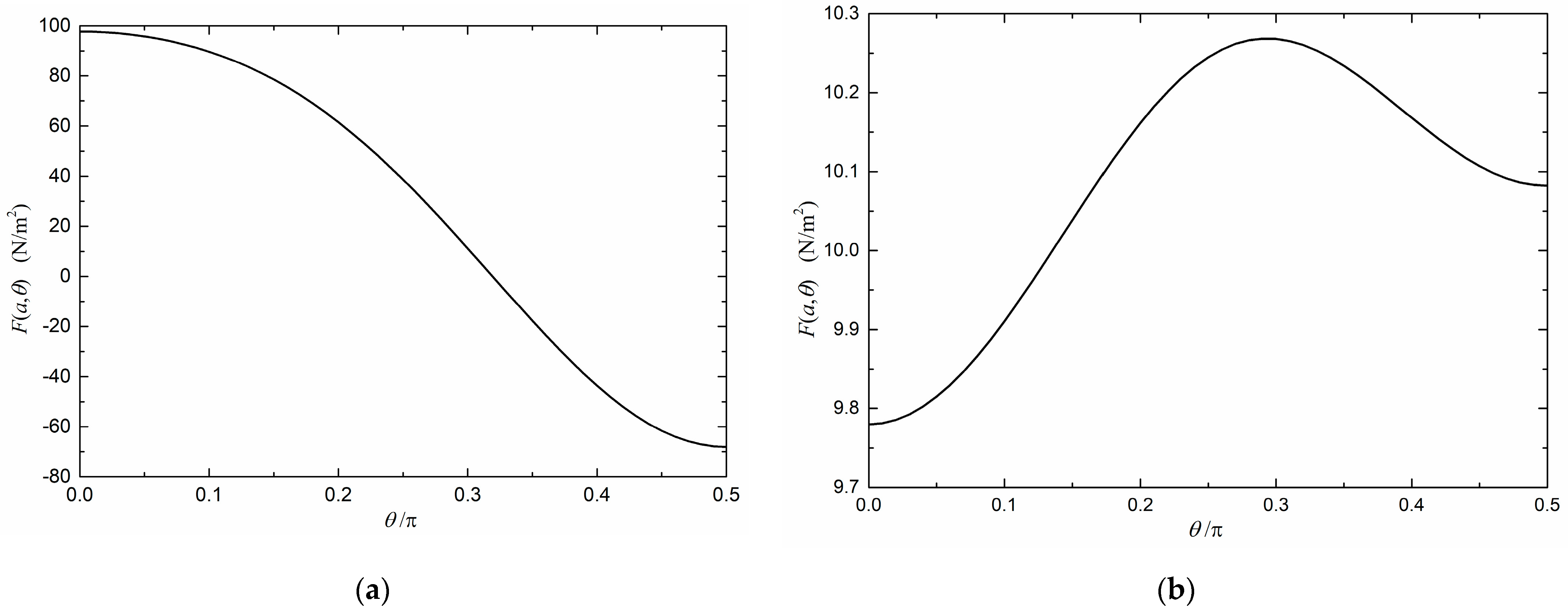
3.1. Positive Uniaxial Intervening Media (ε3|| > ε3⊥)

To perform the numerical calculation, the frequency dependent permittivities of the plates and the intervening media are needed.
We consider plate 1 to be made of gold. The dielectric function can be described by the Drude model [4]
ε 1 ( ξ ) = 1 + ω p 2 ξ ( ξ + γ ) ,
The parameters used for gold: ωp = 1.37 × 10¹⁶ rad/s and γ = 5.32 × 10¹³ rad/s [4].
Plate 2 is considered to be made of silica. We neglect the dc conductivity and use the model that have been used in [24,25],
ε 2 ( ξ ) = 1 + j = 1 3 C I R , j ξ / ω I R , j 2 + 1 + C U V ξ / ω U V 2 + 1 ,
with the values of the parameters: CIR,1 = 0.829, CIR,2 = 0.095, CIR,3 = 0.798, ωIR,1 = 0.867 × 10¹⁴ rad/s, ωIR,2 = 1.508 × 10¹⁴ rad/s, ωIR,3 = 2.026 × 10¹⁴ rad/s, CUV = 1.098, and ωUV = 2.034 × 10¹⁶ rad/s.
The uniaxial intervening media is chosen to be BeO, which was used in a similar calculation in [25]. The dielectric function can be described by the following model [25,26]
ε 3 ( ξ ) = 1 + C I R ξ / ω I R 2 + 1 + C U V ξ / ω U V 2 + 1 ,
and
ε 3 ( ξ ) = 1 + C I R ξ / ω I R 2 + 1 + C U V ξ / ω U V 2 + 1 ,
with the values of the parameters: CIR,⊥ = 4.04, CUV,⊥ = 1.90, ωIR, ⊥ = 1.3 × 10¹⁴ rad/s, ωUV, ⊥ = 1.98 × 10¹⁶ rad/s, CIR,|| = 4.70, CUV, || = 1.951, ωIR, || = 1.4 × 10¹⁴ rad/s, and ωUV, || = 2.37 × 10¹⁶ rad/s.
Figure 2 provides the Casimir force F(a, θ) between plate 1 (gold) and plate 2 (silica), separated by a uniaxial media (BeO). The angle between the optical axis of the intervening media and the surface normal is θ = π/4. A positive value of F(a, θ) indicates that the force is repulsive. One can find in Figure 2 that the Casimir force F(a, θ) is repulsive at all distances.
Figure 3 illustrates the dependence of the Casimir force on the tilt angel θ between the optical axis of the intervening media and the surface normal (at a = 10 nm). Figure 3a,b show the cases of two identical plates. In these cases, the force must be attractive. It can be found in Figure 3a,b that the attraction is strongest at θ = 0 or when the optical axis of the intervening media is perpendicular to the plates. The attraction decreases when θ increases, which means the force is more attractive when the tilt angle of the optical axis of the intervening media is small. It can also be understood as indicating that the nonzero θ produces a “repulsive” contribution and reduces the attraction. Similar trends could also be found in [18], which studied only the case of two identical plates when the force was always attractive. However, the case when the force is repulsive might be more interesting. Figure 3c shows us that the repulsive force also has its greatest magnitude at θ = 0, and it decreases when θ increases, which is similar to the case of the attractive force. In this case, the contribution of the nonzero θ seems to be “attractive”, which is different from the previous case when the force is always attractive.
Therefore, no matter whether the force is repulsive or attractive, the magnitude of the force has its maximum at θ = 0, and it decreases as θ increases. The force is more attractive when the tilt angle is small if the force is attractive, while it is more repulsive when the tilt angle is small if the force is repulsive.
We introduce
r a , θ = F a , θ F a , 0 F a , 0
to describe the relative angle variation of the force. Figure 3d compares the relative angle variation of the force when the plates are made of different materials, which confirms that the magnitude of the force decreases as θ increases, no matter whether the force is attractive or repulsive. It also can be found that the relative angle variation of the force could be greater when the metallic plate is involved.
The calculations above are based on the use of BeO as the intervening media. However, these features may be common to most positive uniaxial intervening media (ε3|| > ε3⊥).

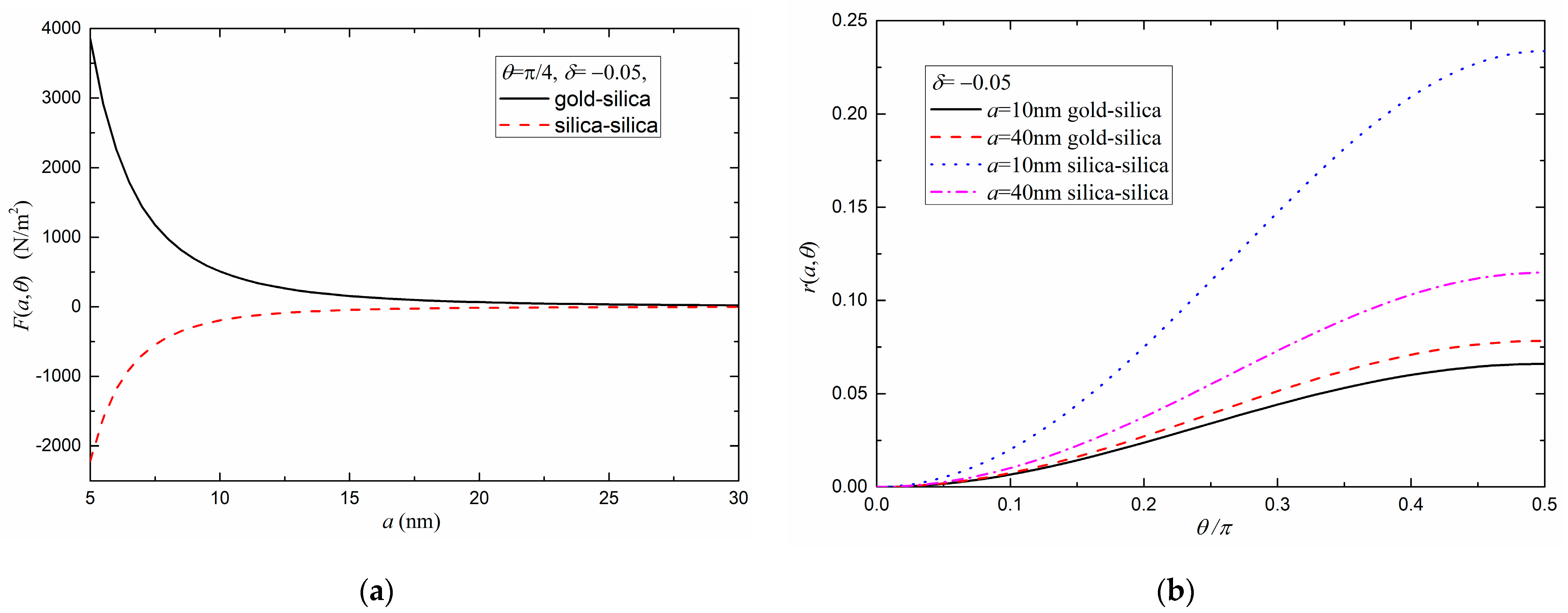
3.2. Negative Uniaxial Intervening Media (ε3|| < ε3⊥)

Let us turn to the case of negative uniaxial intervening media (ε3|| < ε3⊥). Due to the lack of the information about the dielectric functions of real negative uniaxial intervening media, we cannot directly use (13) and (14) to describe the dielectric functions of the negative uniaxial intervening media. Instead, we can use the method that was used in our previous study [22,23,24]. We introduce the degree of anisotropy as
δ = ε 3 ε 3 1
If ε3⊥ is still described by
ε 3 ( ξ ) = 1 + C I R ξ / ω I R 2 + 1 + C U V ξ / ω U V 2 + 1 ,
ε3|| can be determined by (16). δ = 0 means the intervening media is isotropic. When δ > 0, ε3|| > ε3⊥, which indicates that the intervening media is a positive uniaxial material. When δ < 0, ε3|| < ε3⊥, which indicates that the intervening media is a negative uniaxial material. The following discussion in this section will be mainly focused on δ < 0. Equations (16) and (17) will be used only in this subsection.
The numerical simulation of the Casimir force between parallel isotropic plates separated by uniaxial intervening media (δ = −0.05) is shown in Figure 4a. The parameters used for ε3⊥ in (17) are the same as those used in our previous works [23,24], i.e., the parameters for bromobenzene: CIR = 2.967, CUV = 1.335, ωIR = 5.47 × 10¹⁴ rad/s and ωUV = 1.28 × 10¹⁶ rad/s. ε3|| is determined by (16). The plates are made of gold or silica. In Figure 4a, negative values correspond to an attraction, while positive values correspond to a repulsion.
It can be found in Figure 4a that the forces do not switch their directions as the distance changes. For the case of two silica plates (the dashed line in Figure 4a), the force is always attractive. Let us turn to the case when one plate is made of gold and the other is made of silica (the solid line in In Figure 4a). As |δ| used in Figure 4 is small, the inequality ε1 > ε3⊥ > ε3|| > ε2 is satisfied, which makes the force always repulsive.
Figure 4b provides the relative angle variation of the force when the plates are made of different materials. r(a, θ) is also defined in (15). Figure 4b shows a “reversed” trend when compared with Figure 3d. It can be found that no matter whether the force is attractive or repulsive, it has its smallest magnitude at θ = 0, and it increases as θ increases. The greatest magnitude is achieved at θ = π/2, or when the optical axis of the intervening media is parallel to the surface of the plates. This difference is reasonable, as we used a negative δ (ε3⊥ > ε3||) in Figure 4b, while BeO used in Figure 3d is a positive uniaxial media (ε3⊥ < ε3||).
As we have already mentioned that the force does not switch its direction in Figure 4b, the question arises of whether there will be something different if the attractive–repulsive transition occurs. In our previous works [22,23,24], we have shown that the Casimir force can switch its direction as the separation changes when the optical axis of the intervening media is perpendicular or parallel to the plates. Our current study shows that a similar attractive–repulsive transition also can happen with other optical axis orientations. As can be seen in the Figure 5, when θ = π/4, the Casimir force is attractive at small distances and switches to repulsive when the distance is larger. In Figure 5, one plate is made of gold and the other one is made of silica. The parameters used for ε3⊥ are the same as those used in Figure 4. According to our previous works [23,24], to make the attractive–repulsive transition appear, we need the inequality ε1 > ε3⊥ > ε3|| > ε2 only to be satisfied at a relatively small frequency range while being broken at other frequency ranges. As |δ| used in Figure 4 (the solid line) is small, the inequality ε1 > ε3⊥ > ε3|| > ε2 is satisfied in a relatively large frequency range, which makes the force always repulsive. However, δ = −0.19 was used in Figure 5. This means that the inequality ε1 > ε3⊥ > ε3|| > ε2 is only satisfied at a low frequency range (<1015 rad/s). This indicates that the low frequency modes may contribute to the repulsive force, while high frequency modes may contribute to the attractive force. With a smaller separation, where the high frequency modes are dominant, the force is attractive. However, at greater separation, the low frequency modes become dominant. That is why the force switches to repulsive as the separation increases. This is similar to the case in [23].
Interestingly, we also find that it is possible for the Casimir force to switch its direction as the orientation of the optical axis varies. It is apparent from Figure 6a that both the magnitude and the direction of the force are affected by the orientation of the optical axis of the intervening media. The force is repulsive when the optical axis is perpendicular to the plates (θ = 0), and the repulsive force becomes weaker as tilt angle θ increases. As θ becomes greater, the force switches its direction and becomes stronger. When the optical axis is parallel to the plates (θ = π/2), the force is already attractive. Although the calculation was not performed with the data of real material, it indicates that it is theoretically possible that the Casimir force can switch its direction when the orientation of the optical axis varies.
In Figure 3 and Figure 4, the magnitude of the force increases or decreases with θ monotonically. However, Figure 6b shows us that, at a = 30 nm, the relation between the magnitude of the force and θ could be nonmonotonic. This indicates that it is theoretically possible that the force is strongest at an angle between 0 and π/2, depending on the dielectric properties of the material.

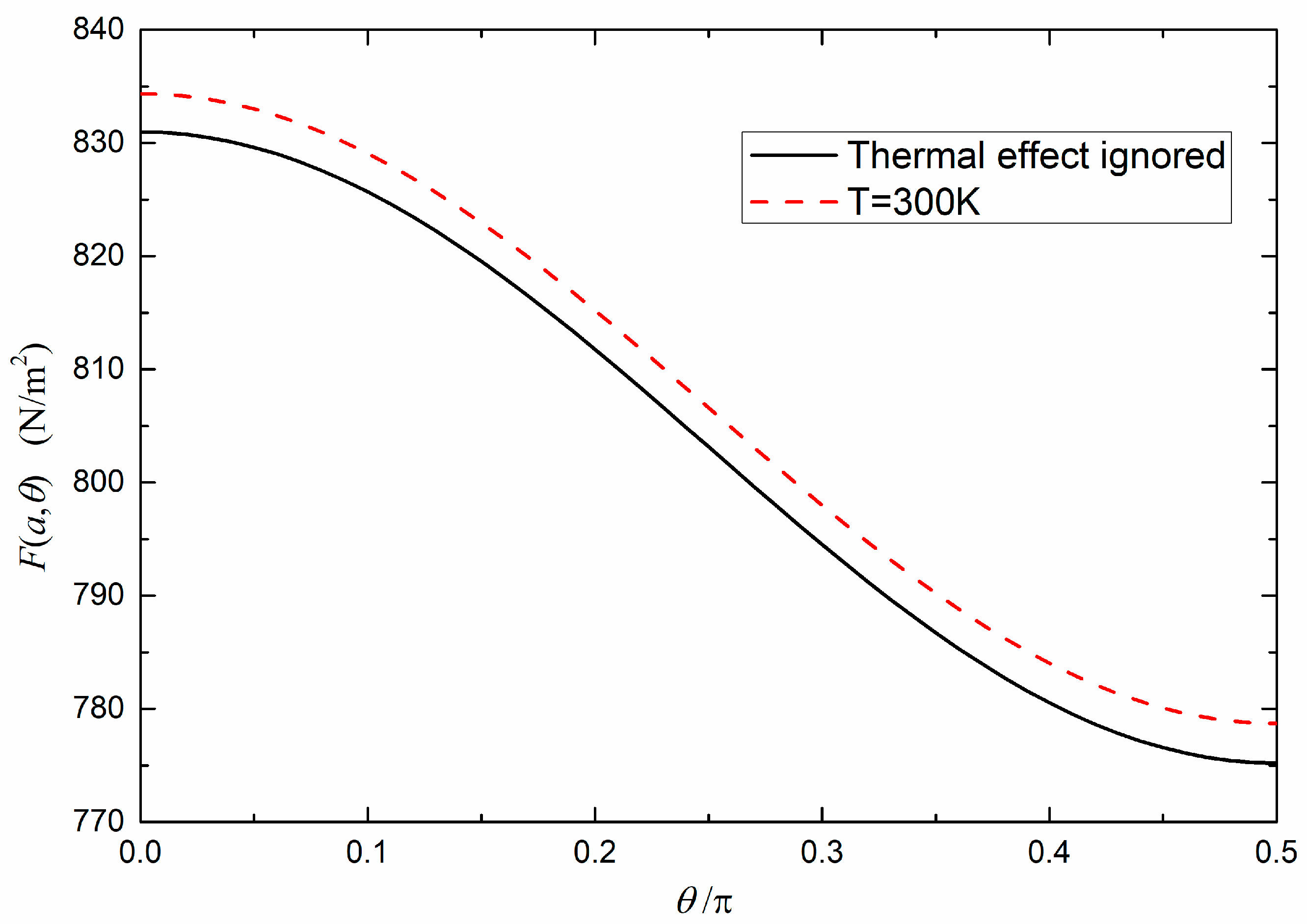
3.3. The Infulunce of Non-Zero Temperature

To calculate the Casimir force at non-zero temperature, one could just replace the integral over ξ by a summation by means of d ξ 2 π K b T m with ξ ξ m in Equation (9) [12,16,24].
F T a , θ = K b T π c 3 1 p d p m = 0 ε 3 3 / 2 ξ m 3 p 1 Q T E Q T E + ε 3 ε 3 z z P 1 Q T M Q T M
where the prime indicates that the m = 0 term is counted half with weight.
If we consider the configuration of the system to be gold-BeO-silica and use Equations (11)–(14) to describe the dielectric functions, Equation (18) can be transformed into
F T a , θ = F m = 0 T + K b T π c 3 1 p d p m = 1 ε 3 3 / 2 ξ m 3 p 1 Q T E Q T E + ε 3 ε 3 z z P 1 Q T M Q T M
with
F m = 0 T = K b T 8 π a 3 ε 3 z z 0 2 ε 3 0 ε 3 0 L i 3 X
where L i 3 X is the polylogarithm function and
X = 1 ε 2 0 ε 3 0 ε 3 0 1 + ε 2 0 ε 3 0 ε 3 0
The numerical result of the thermal Casimir force is shown in Figure 7. All the parameters used here are the same as those used in Figure 3c. As can be seen from Figure 7, the thermal effect does not have a significant effect on the force. This result is reasonable, as the separations considered in current study are small [24]. For the case of larger separations, the role of thermal effects in the Casimir force through an anisotropic material is examined in [25].

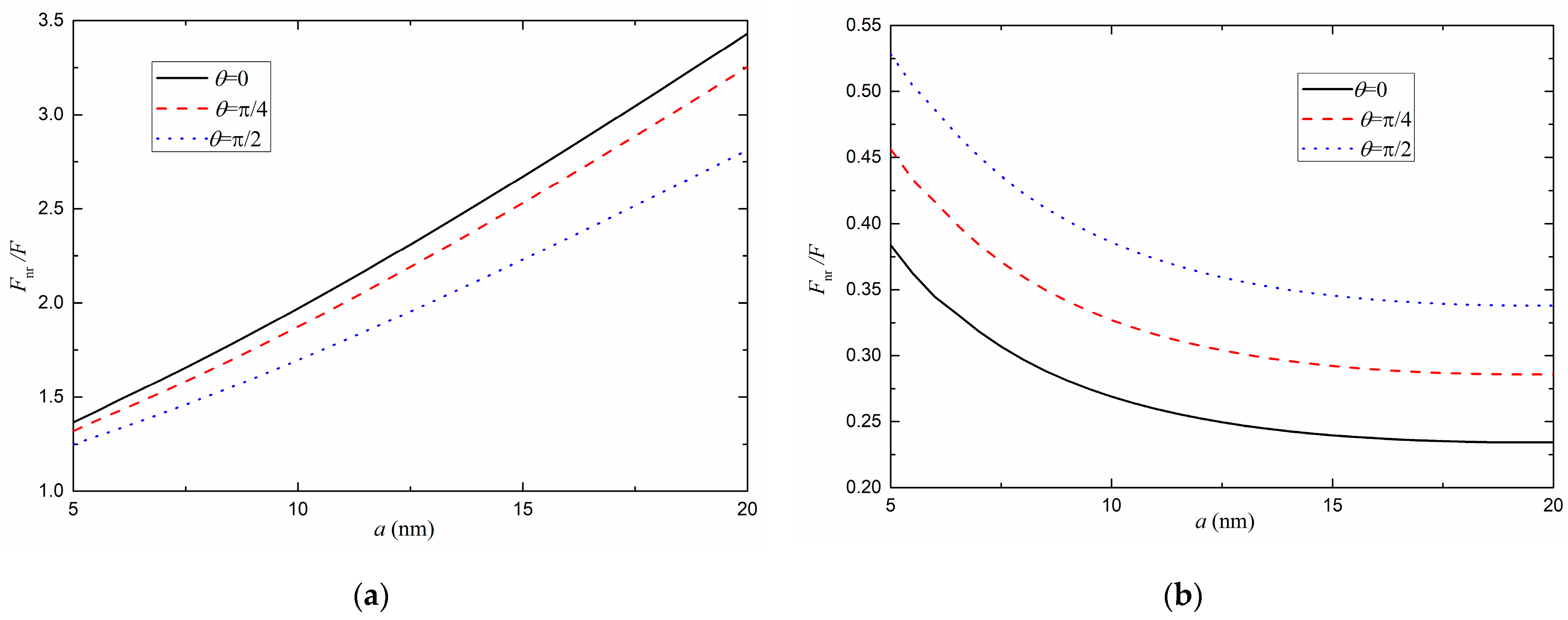
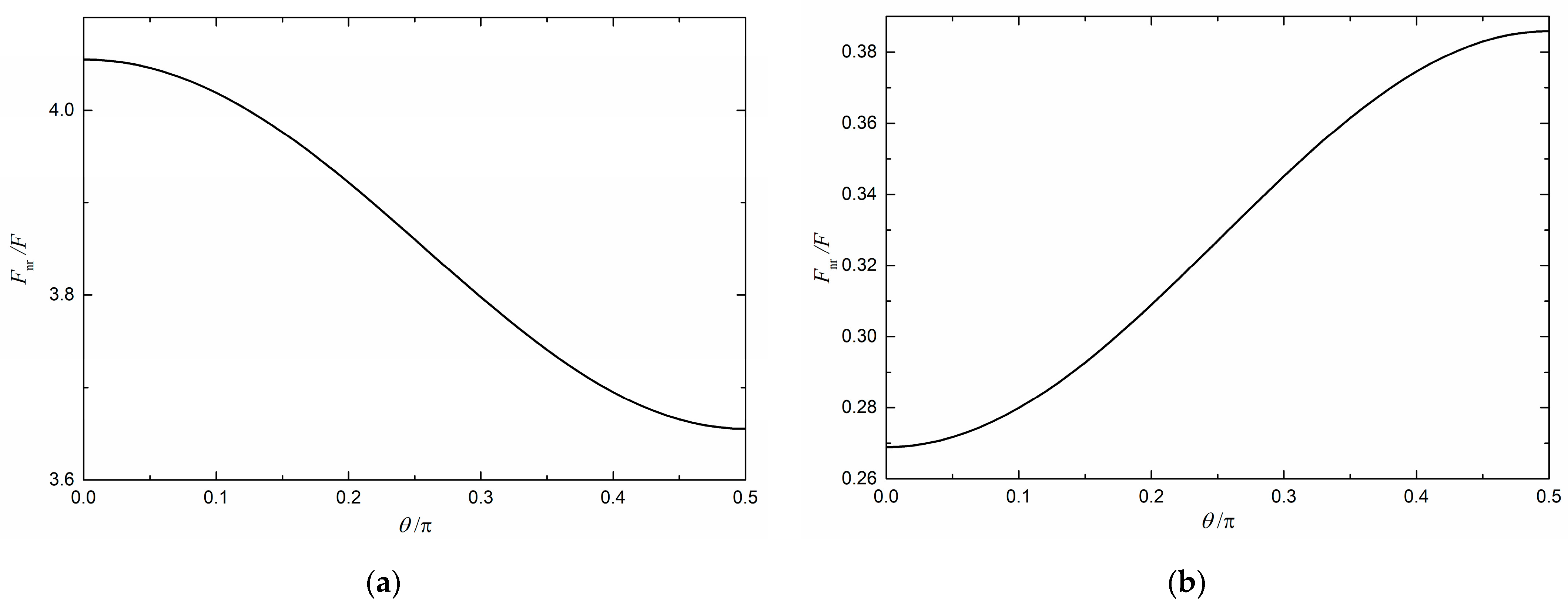
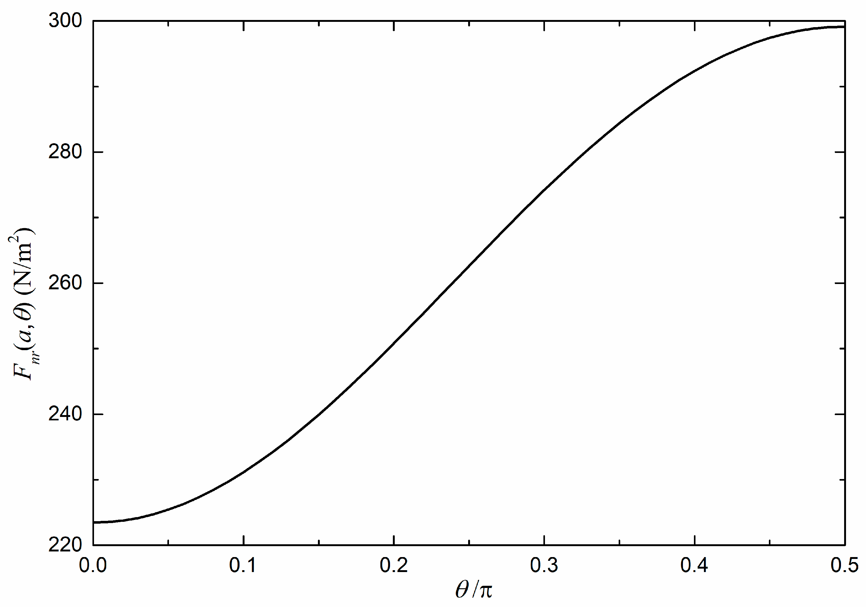
4. A Comparison between Retarded and Nonretarded Results

As motioned by Mostepanenko [25], a nonrelativistic approximation may result in considerable errors when the optical axis is perpendicular to the surface of the plates. In this section, a more detailed calculation will be performed to compare the relativistic and nonrelativistic results at different optical axis orientations.
In the nonrelativistic limit, only the TM contribution survives, and Equation (9) becomes
F n r a , θ = 2 π 2 0 k d k 0 ε 3 ε 3 ε 3 z z d ξ 1 Q T M , n r Q T M , n r ,
with
Q T M , n r = 1 ε 1 ε 3 ε 3 ε 1 + ε 3 ε 3 ε 2 ε 3 ε 3 ε 2 + ε 3 ε 3 e x p 2 a ε 3 ε 3 ε 3 z z k ,
where the subscript “nr” indicates a result in the nonrelativistic limit.
We use the value of F n r / F to compare the relativistic and nonrelativistic results of the magnitude of the force. Fnr is calculated with Equation (22), while F is calculated with Equation (9). The intervening media is chosen to be BeO. The parameters of the materials are the same as those used in Figure 2 and Figure 3. In Figure 8a, both plates are made of silica, and the Casimir force is attractive. It is apparent form Figure 8a that F n r / F is greater than 1, which indicates that the nonrelativistic approximation could significantly overestimate the attraction, even at small distances. Let us turn to the case of a repulsive Casimir force. In Figure 8b, one plate is made of gold and the other one is made of silica, and the Casimir force is repulsive. It is apparent from Figure 8b that F n r / F is much smaller than 1, which indicates that the nonrelativistic approximation could significantly underestimate the repulsion, even at small distances.
Figure 9a,b present the values of F n r / F with different optical axis orientations when the distance between the plates is 10 nm. It can be found that, no matter whether the force is attractive or repulsive, F n r / F is closer to 1 when θ = π/2, and further from 1 when θ = 0. This indicates that the nonrelativistic approximation induces the least error when the optical axis of the intervening media is parallel to the plates and induces the greatest error when the optical axis of the intervening media is perpendicular to the plates.
Interestingly, the nonrelativistic approximation not only induces error to the magnitude of the force; it could even fail to predict the trends of the Casimir force. Figure 10 shows the nonrelativistic Casimir force with different optical axis orientations at a = 10 nm. All the parameters are the same as those used in Figure 3c. According to Figure 3c, the magnitude should decrease as θ increases. However, Figure 10 depicts a “reversed” trend, which means that even the trends predicted by the nonrelativistic approximation at 10 nm might be doubtable.

5. The Dependence of the Casimir Energy on the Orientation of the Optical Axis of the Intervening Media

Equations (6)–(8) provide a relationship between the Casimir energy and the orientation of the optical axis of the intervening media, which may be associated with the question of which orientation is the more stable.
Figure 11 compares the angle variation of the Casimir energy at a = 10 nm in different cases. The Casimir energy in Figure 11 is calculated relative to the value at θ = 0. The parameters of the materials are the same as those used in Figure 2 and Figure 3. When the two plates are identical (the solid line and the dash line in Figure 10), the Casimir energy has its smallest value at θ = 0, which indicates that the most stable orientation is achieved when the optical axis of the intervening media is perpendicular to the surface of the plates. We noted that the Casimir force in this case is attractive. When one plate is made of gold and the other is made of silica (the dotted line in Figure 11), the force is repulsive according to our calculation in Section 3. In this case, the Casimir energy has its smallest value at θ = π/2, which indicates that the most stable orientation is achieved when the optical axis of the intervening media is parallel to the surface of the plates.

6. Conclusions

We have studied the effects due to the orientation of the optical axis of the intervening media on the Casimir effect in the configuration of two parallel isotropic plates separated by an anisotropic media.
The Casimir force has been calculated. The results exhibited a dependence on the orientation of the optical axis of the intervening media. It is possible for the Casimir force to switch its direction when the orientation of the optical axis of the intervening media varies.
For positive uniaxial intervening media (ε3|| > ε3⊥), the numerical calculations revealed that, no matter whether the force is repulsive or attractive, the force is strongest when the optical axis of the intervening media is perpendicular to the surface of the plates, and it decreases monotonically as the tilt angle increases. This feature is may apply to most positive uniaxial intervening media (ε3|| > ε3⊥). For negative uniaxial intervening media (ε3|| < ε3⊥), if the force is always in the same direction at all distances, the force is weakest when the optical axis is perpendicular to the surface of the plates and it increases as the tilt angle increases. If the force can switch its direction as the distance changes, the relation between the magnitude of the force and the tilt angle might even be nonmonotonic. This indicates that the strongest force can be achieved at any optical axis orientation, depending on the dielectric properties of the plates and the intervening media.
We have compared the relativistic and nonrelativistic results with different optical axis orientations. A nonrelativistic approximation could induce considerable errors to the estimation of the magnitude of the force, even at small distances. It could significantly underestimate the attraction or overestimate the repulsion. This error is even greater when the optical axis of the intervening media is perpendicular to the surface of the plate. Strikingly, a nonrelativistic approximation might even fail to predict the trends of the Casimir force at small distances.
The Casimir energy has also been calculated. If the force is always attractive, the Casimir energy has its smallest value when the optical axis of the intervening media is perpendicular to the surface of the plates. If the force is always repulsive, the Casimir energy has its smallest value when the optical axis of the intervening media is parallel to the surface of the plates. This feature may apply to most positive uniaxial intervening media (ε3|| > ε3⊥).
Although, theoretically speaking, the effect due to the optical orientation can be detected by technology based on AFM, it is still very difficult to confirm experimentally with high accuracy, as the relative change of the force is very weak. Another challenge comes from the technique to bring the plates close to each other with a parallel alignment. Therefore, we believe that the precise observation of these effects remains challenging.
Due to the lack of the information about the dielectric functions of different uniaxial intervening media, especially negative uniaxial materials (ε3|| < ε3⊥), it was difficult to include many real materials in the present numerical calculations, which might be one of the limitations of the current study. Further research covering more real uniaxial materials is still needed.

Author Contributions

All the authors have participated in the research for this paper. All authors have read and agreed to the published version of the manuscript.

Funding

This work was partially supported by the National Natural Science Foundation of China (Grant No. 11605050, and Grant No. 91636221).

Data Availability Statement

The data presented in this study are available on request from the corresponding author. The data are not publicly available due to privacy.

Acknowledgments

The authors owe all the former works on the Casimir effect for the inspiration for this article.

Conflicts of Interest

The authors declare no conflict of interest.

References

  1. Casimir, H.B.G. On the Attraction Between Two Perfectly Conducting Plates. Proc. Kon. Ned. Akad. Wet. 1948, 51, 793. [Google Scholar]
  2. Lifshitz, E.M. The Theory of Molecular Attractive Forces Between Solids. Sov. Phys. JETP 1956, 2, 73. [Google Scholar]
  3. Dzyaloshinskii, I.E.; Lifshitz, E.M.; Pitaevskii, L.P. The General Theory of van der Waals Forces. Adv. Phys. 1961, 10, 165–209. [Google Scholar] [CrossRef]
  4. Bordag, A.; Mohideen, U.; Mostepanenko, V.M. New developments in the Casimir effect. Phys. Rep. 2001, 353, 1–205. [Google Scholar] [CrossRef]
  5. Milton, K.A. The Casimir Effect: Physical Manifestations of Zero-Point Energy; World Scientific: Singapore, 2001; ISBN 978-981-02-4397-5. [Google Scholar]
  6. Klimchitskaya, G.L.; Mohideen, U.; Mostepanenko, V.M. The Casimir force between real materials: Experiment and theory. Rev. Mod. Phys. 2009, 81, 1827. [Google Scholar] [CrossRef]
  7. Parsegian, V.A.; Weiss, G.H. Dielectric Anisotropy and the van der Waals Interaction between Bulk Media. J. Adhes. 1972, 3, 259. [Google Scholar] [CrossRef]
  8. Barash, Y.S. Moment of van der Waals forces between anisotropic bodies. Radiophys. Quantum Elec. 1978, 21, 1138. [Google Scholar] [CrossRef]
  9. Munday, J.N.; Iannuzzi, D.; Barash, Y. Torque on birefringent plates induced by quantum fluctuations. Phys. Rev. A 2005, 71, 042102. [Google Scholar] [CrossRef]
  10. Somers, D.A.T.; Munday, J.N. Casimir-Lifshitz Torque Enhancement by Retardation and Intervening Dielectrics. Phys. Rev. Lett. 2017, 119, 183001. [Google Scholar] [CrossRef]
  11. Shao, C.G.; Tong, A.H.; Luo, J. Casimir torque between two birefringent plates. Phys. Rev. A 2005, 72, 022102. [Google Scholar] [CrossRef]
  12. Deng, G.; Liu, Z.Z.; Luo, J. Impact of magnetic properties on the Casimir torque between anisotropic metamaterial plates. Phys. Rev. A 2009, 80, 062104. [Google Scholar] [CrossRef]
  13. Romanowsky, M.B.; Capasso, F. Orientation-dependent Casimir force arising from highly anisotropic crystals Application to Bi2Sr2CaCu2O8+δ. Phys. Rev. A 2008, 78, 042110. [Google Scholar] [CrossRef]
  14. Parashar, P.; Milton, K.; Shajeshand, K.V.A.; Schaden, M. Electromagnetic semitransparent δ-function plate: Casimir interaction energy between parallel infinitesimally thin plates. Phys. Rev. D 2012, 86, 085201. [Google Scholar] [CrossRef]
  15. Shao, C.G.; Zheng, D.L.; Luo, J. Repulsive Casimir effect between anisotropic dielectric and permeable plates. Phys. Rev. A 2006, 74, 012103. [Google Scholar] [CrossRef]
  16. Deng, G.; Liu, Z.Z.; Luo, J. Attractive-repulsive transition of the Casimir force between anisotropic plates. Phys. Rev. A 2008, 78, 062111. [Google Scholar] [CrossRef]
  17. Somers, D.A.T.; Munday, J.N. Conditions for repulsive Casimir forces between identical birefringent materials. Phys. Rev. A 2017, 95, 022509. [Google Scholar] [CrossRef]
  18. Kornilovitch, P.E. Van der Waals interaction in uniaxial anisotropic media. J. Phys. Condens. Matter 2013, 25, 035102. [Google Scholar] [CrossRef]
  19. Poulin, P.; Stark, H.; Lubensky, T.C.; Weitz, D.A. Novel Colloidal Interactions in Anisotropic Fluids. Science 1997, 275, 1770. [Google Scholar] [CrossRef]
  20. Akhmetov, A.T.; Valiev, A.A.; Rakhimov, A.A.; Sametov, S.P. Anisotropic Properties of Blood in a Vessel with Stenosis. Dokl. Phys. 2018, 63, 476. [Google Scholar] [CrossRef]
  21. Nahmad-Rohen, A.; Contreras-Tello, H.; Morales-Luna, G.; García-Valenzuela, A. On the effective refractive index of blood. Phys. Scr. 2016, 91, 015503. [Google Scholar] [CrossRef]
  22. Gang, D.; Hua, T.B.; Ling, P.; Ni, H.; Rong, Z.J. Casimir force between parallel plates separated by anisotropic media. Phys. Rev. A 2015, 91, 062126. [Google Scholar]
  23. Deng, G.; Pei, L.; Hu, N.; Liu, Y.; Zhu, J.R. The impact of the anisotropy of the media between parallel plates on Casimir force. Symmetry 2018, 10, 61. [Google Scholar] [CrossRef]
  24. Deng, G.; Lv, C.Y.; Su, Q.; Pei, L.; Hu, N.; Liu, Y. The Casimir force between parallel plates separated by anisotropic media with in-plane optical axis. Europhys. Lett. 2019, 126, 40002. [Google Scholar] [CrossRef]
  25. Mostepanenko, V.M. Special features of the thermal Casimir effect across a uniaxial anisotropic film. Phys. Rev. A 2015, 92, 012911. [Google Scholar] [CrossRef]
  26. Bergstrom, L. Hamaker constants of inorganic materials. Adv. Colloid Interface Sci. 1997, 70, 125. [Google Scholar] [CrossRef]
Figure 1. Schematic of the system under investigation. The dashed line indicates the direction of the optical axis of the intervening media: (a) The overall geometry: two parallel isotropic plates separated by a third uniaxial media; (b) Approximate schematic of the system: two isotropic semi-infinite plates separated by a third uniaxial media.
Universe 09 00216 g001
Figure 2. The Casimir force between a gold plate and a silica plate separated by BeO. The angle between the optical axis of the intervening media (BeO) and surface normal is π/4.
Universe 09 00216 g002
Figure 3. (Colored line) The dependence of the Casimir force on the orientation of the optical axis of the intervening material (BeO). a = 10 nm is used: (a) F(a, θ) vs. θ. Both plates are made of gold; (b) F(a, θ) vs. θ. Both plates are made of silica; (c) F(a, θ) vs. θ. Plate 1: gold, Plate 2: silica; (d) The relative variation of the force r(a, θ) vs. θ.
Universe 09 00216 g003
Figure 4. (Colored line) The Casimir force and its angle variation (δ = −0.05).: (a) F(a, θ) vs. θ; (b) r(a, θ) vs. θ.
Universe 09 00216 g004
Figure 5. (Colored line) The Casimir force between parallel isotropic plates separated by uniaxial intervening media (δ = −0.19).
Universe 09 00216 g005
Figure 6. The dependence of Casimir force on the tilt angle of the optical axis of the intervening material (δ = −0.19). (a) a = 10 nm; (b) a = 30 nm.
Universe 09 00216 g006
Figure 7. The dependence of thermal Casimir force on the orientation of the optical axis of the intervening material (BeO). Plate 1: gold. Plate 2: silica. a = 10 nm is used.
Universe 09 00216 g007
Figure 8. A comparation between relativistic and nonrelativistic results. The intervening media is BeO. F n r / F vs. a: (a) Both plates are made of silica.; (b) Plate 1: gold. Plate 2: silica.
Universe 09 00216 g008
Figure 9. A comparison between relativistic and nonrelativistic results. The intervening media is BeO. F n r / F vs. θ: (a) Both plates are made of silica.; (b) Plate 1: gold. Plate 2: silica.
Universe 09 00216 g009
Figure 10. The nonretarded Casimir force between a gold plate and a silica plate parallelly interacts across a third isotropic media (BeO) at different optical axis orientations. a = 10 nm.
Universe 09 00216 g010
Figure 11. (Colored line) The angle variation of the Casimir energy. The intervening media is BeO. a = 10 nm.
Universe 09 00216 g011
Disclaimer/Publisher’s Note: The statements, opinions and data contained in all publications are solely those of the individual author(s) and contributor(s) and not of MDPI and/or the editor(s). MDPI and/or the editor(s) disclaim responsibility for any injury to people or property resulting from any ideas, methods, instructions or products referred to in the content.

