Article

Overview of Architectural Alternatives for the Integration of ETSI MEC Environments from Different Administrative Domains

by
Luis M. Contreras
1,2,* and
Carlos J. Bernardos
2
1
Telefónica I+D, Telefonica GCTIO, 28050 Madrid, Spain
2
Department of Telematics, Universidad Carlos III de Madrid, 28911 Leganés, Spain
*
Author to whom correspondence should be addressed.
Electronics 2020, 9(9), 1392; https://doi.org/10.3390/electronics9091392
Submission received: 29 July 2020 / Revised: 20 August 2020 / Accepted: 25 August 2020 / Published: 28 August 2020
(This article belongs to the Special Issue Cloud Computing and Applications)

Abstract

:
Multi-access Edge Computing (MEC) is proposed as a standard framework for the provision and consumption of applications and services in proximity to the end-users of network operators. Proximity has been identified as one of the enablers of the forthcoming 5G, where extreme low latency and large bandwidth will be necessary for some services. However, the need of proximity imposes to network operators the necessity of huge investments in order to distribute computing capabilities towards the access. A less investment intensive approach would consist on sharing infrastructures by integrating MEC environments from different operators or providers. This could open the door to new business models on the one hand, as well as to avoid restrictions in terms of space, energy of regulation, on the other. This paper overviews different integration options by analyzing the MEC framework defined by the European Telecommunications Standards Institute (ETSI) and identifying different architectural alternatives as well as the business and technical aspects that need to be taken into consideration for realizing such integration.

1. Introduction

The deployment of future 5G networks will represent an important and challenging source of investment for network operators. Some studies [1,2] reveal the magnitude of the investments necessary for providing the features expected from future 5G services at a coverage similar to the one offered by previous mobile generations. A way of reducing such investments is the approach of sharing infrastructures among competing operators [3], as commonly happening nowadays, and/or the option of hosting mobile virtual network operators (MVNOs) [4] leveraging on the infrastructure already deployed by some mobile network operators (MNOs) in the field. In fact, it is expected that 5G could foster the appearance of local 5G micro operators [5] that can operate a closed network for its own customers, act as neutral host for mobile network operators’ customers, or serve both, offering local context related services and content to complement existing services.
Forthcoming 5G advanced services, demanding low latency and/or high bandwidth, will benefit from location proximity to the end user. The more straightforward manner of providing such proximity is by means of the deployment of computing capabilities towards the access, where content, applications and services can be deployed for facilitating the delivery of such innovative services.
A number of technological options for distributing computing capabilities at the network edge are emerging, such as Multi-access Edge Computing, Fog Computing or Cloudlet paradigms [6,7], each showing different degrees of capillarity and functionality. From all of them, Multi-access Edge Computing (MEC), whose technical specifications are being standardized by the European Telecommunications Standards Institute (ETSI) [8], has emerged as the industrial, standard-based reference platform enabling such delivery in proximity, with an important role expected for 5G [9]. MEC describes an edge system that enables edge applications from the provider or a third party to be executed in a network. These applications, for instance, are related to radio network information, location, etc. Some other advanced services could be enabled like streaming, augmented reality, gaming, etc., as described in [10,11]. Interestingly, the ETSI MEC architectural framework presents the advantage with respect other edge alternatives of an industrial effort on making it coexist with other widely deployed frameworks such as the ETSI Network Function Virtualization [12] and the 3GPP architecture [13], then presenting a roadmap of joint interworking, resulting on an industry backed-up choice for addressing the edge computing solution space. Thus, this paper concentrates on ETSI MEC as subject of analysis.
In this new ecosystem demanding large investments and involving multiple actors, the integration of MEC environments from different stakeholders (in scenarios enabled by MVNOs, local 5G micro operators or infrastructure sharing) can largely benefit and assist on the generalization of the availability of such new 5G services. The integration of those environments requires the interaction of different administrative domains, imposing some challenges like security, discovery of resources and services, etc. Such a multi-domain scenario, however, has not been yet specified. Thus, the motivation of this paper is to analyze the different alternatives of multi-domain interworking feasible in MEC from an architectural point of view, in order to determine initial implications of such multi-provider scenarios. The contribution is threefold: (i) to describe distinct integration models as enabled by the ETSI MEC architecture definition; (ii) to elicit business and technical implications for each of that models; and (iii) to summarize the interactions among administrative domains in the deployment of MEC applications in a multi-domain scenario.
The structure of the paper is as follows. Section 2 briefly discuss different technological approaches for edge computing. Section 3 introduces the ETSI MEC architecture and defines the concept of multi-domain MEC. A number of implications for both business and technical aspects have to be taken into account when defining such integration. The paper overviews them in Section 4. Section 5 proposes different alternatives of integration at different levels, nominally at infrastructure, platform and service levels. Section 6 describes the interactions among MEC domains for the deployment of an MEC application. Finally, Section 7 summarizes the main findings of the paper with some concluding remarks.

2. Technological Alternatives for Computing at the Network Edge

Different technological alternatives have emerged in recent years promoting the deployment of distributed computing environments towards the edge of the network, looking to enable new advanced services. Industry and academia have been actively researching on this area where several architectures and approaches have been proposed, existing several works surveying their different aspects and characteristics (e.g., [14,15,16,17,18,19]). Despite the purpose is common to all of them, which is essentially the extension centralized cloud capillarity, the approach taken is slightly different.
Multi-access Edge Computing specifies a complete orchestration architectural framework, initially conceived for smooth integration with carrier′s mobile networks and extended later in scope to fixed services. MEC defines a number of well-defined open and standard APIs for consuming information generated by distinct services and applications, which can be dynamically deployed on top of a virtualized infrastructure.
Fog computing concept has been extensively proposed in the context of Internet of Things (IoT) and sensor networks, assuming the deployment of some computing and storage capabilities, even minimal, in IoT and sensor devices at the far edge (that is, on end-user or near-user edge devices). All those devices together can constitute a large base of compute substrate when considering the aggregation of their capabilities.
Finally, the Cloudlet approach advocates for the deployment of localized micro data centers very close to mobile devices in support of the execution of certain applications, mainly assisting on computation offloading tasks.
A wider discussion of the three approaches can be found in [6,7,20]. Table 1 summarizes some relevant aspects for each of these technological alternatives, as well as referring to specific surveys for each of them. From all of the alternatives, MEC emerges as the one more consolidated as solution for carrier networks, including an integration path with NFV and 3GPP architectures as primary evolution paradigms for telecom operator networks. As consequence, this paper focus on the formal specification of ETSI MEC architecture as baseline for the analysis of multi-domain scenarios.

3. Integration of Multi-Domain MEC Environments

The MEC framework is originally defined as an environment managed and administered by a single network operator, which controls a number of edge computing sites defining an area of coverage. From this perspective, Current MEC architecture frameworks do not yet consider a scheme of integration from multiple administrative domains, where different providers offering (totally or partially) MEC capabilities conform an overarching, wider MEC system.
This section briefly describes the MEC architecture as originally proposed by ETSI.

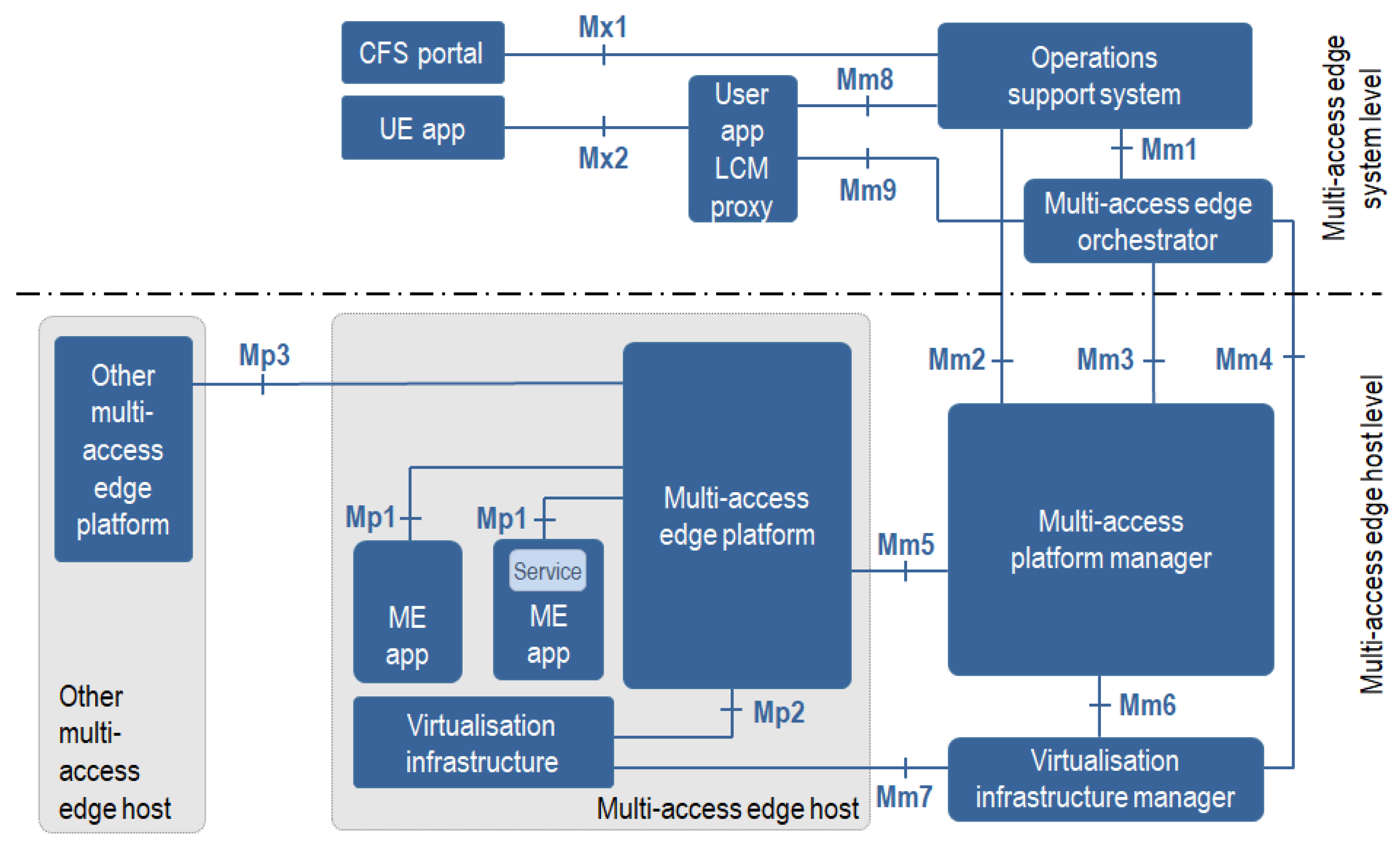
3.1. MEC Architecture

The MEC reference architecture is described in [27], and graphically represented in Figure 1. It is composed on functional components and the reference points between them. It also includes a number of mobile edge services that complement the overall solution.
As seen in Figure 1, the MEC framework differentiates among mobile edge system and mobile edge hosts levels. The Multi-access Edge System (MES) consists of a number of multi-access edge hosts and the multi-access edge management entities necessary to execute multi-access edge applications within an operator network.
The Multi-access Edge Host (MEH) is an entity that contains a Multi-access Edge Platform (MEP) and a virtualization infrastructure.
The MEP provides a functional environment where applications can discover, advertise, consume and offer multi-access edge services. The MEP controls the data-plane in the virtualization infrastructure following a Software Defined Networking (SDN) approach, configures the DNS proxy/server in the MEH based on DNS records obtained from the multi-access edge platform manager, and provides access to persistent storage and time of day information.
The virtualization infrastructure is, generally speaking, a Network Function Virtualization Infrastructure (NFVI) as the one described in [28], which provides compute, storage, and network resources, for running multi-access edge applications on top of it. The virtualization infrastructure includes a data plane that executes the traffic rules received by the MEP, routing the traffic among applications, services, DNS server/proxy, and both local networks and external networks.
Then, the multi-access edge applications, running as virtual machines, are instantiated on the virtualization infrastructure of the mobile edge host (forming an NFVI point of presence, or NFVI-PoP) based on configuration or requests validated by the mobile edge management. They can either consume or provide multi-access edge services present in the MEH. These applications could be even relocated to another multi-access edge host, if supported by the system and the application. Typically, they will have associated rules and requirements (e.g., traffic redirection, DNS re-configuration, maximum latency, etc.), that will be enforced by the multi-access edge system level management.
The Multi-access Edge Platform Manager (MEPM) will act as the element management of the MEP, performing the management of the application rules, including service authorization, traffic rules, DNS configuration, conflict resolution, etc., and also performing the lifecycle management of the multi-access edge applications, including the notifications towards the orchestrator of any application related lifecycle event. Finally, through the interaction with the VIM, it will receive virtual resource fault reports and performance measurements coming from events in the virtualization infrastructure.
Already at system level, the MEO maintains an overall view of the system and multi-access edge hosts, including available resources, available services and topology. It selects the appropriate host for each application, satisfying its rules and requirements, then triggering the application instantiation, relocation and termination. The MEO is also in charge of on-boarding the application packages.
Finally, the MEC architecture is completed by operation support systems (OSS). These OSSs can receive requests from external entities, either from the user application lifecycle manager proxy (UA-LCM proxy), or the customer facing service (CFS) portal, for multi-access edge application instantiation, termination or relocation, determining if such requests can be granted, and in that case, forwarding granted requests to the orchestrator. These OSSs will also allow the network operator to trigger management and control actions, including the configuration of policies for the execution of the applications.
Apart from these functional blocks and components, the MEC architecture defined a number of reference points among them. These have been summarized in Table 2, presenting the components involved as well as the main scope of each reference point. In this paper we will analyze the impact of the multi-domain approach on those reference points for the different scenarios evaluated.
From all these reference points, ETSI MEC does not intend at this stage to further specify a number of them, such as Mm5, Mm7, Mm8, Mm9, Mx1 and Mp2.

3.2. Host Interconnection in MEC

MEC natively considers the possibility of integration with other multi-access edge hosts through the Mp3 reference point. This reference point between multi-access edge platforms is intended to be used for control interconnection between Multi-access Edge Platforms (MEPs) of both a local and a remote Multi-access Edge Hosts. Such remote MEH could pertain, in principle, to a different administrative domains, even though this is not detailed in MEC specifications.
Mp3 allows for supporting mobility in an MEC system, in order to enable continuity of the service and facilitating relocation or mobility of an application (including application–specific user-related information). Functional details with respect to gaps to be supported in this reference point have been described in [29]. The implication of this interconnection is further elaborated in Section 5.
However, there could be additional multi-domain dimensions, not addressed by the ETSI MEC specifications. For instance, there could be third party infrastructure owners that could interconnect their assets with MEC operators in order to increase the coverage footprint. Similarly, there could be also the case that application owners would require to make use of the capabilities from different (and complementary) MEC operators to increase their coverage. It seems clear that a single operator will not be able to cope with all the necessary infrastructure for providing continuous stratum of edge computing even in a single country. It can be expected that a variety of providers start to emerge offering some of that capabilities because of different reasons (e.g., municipalities covering monumental areas, tower companies leveraging on their assets at the very edge, private networks monetizing excess capacity, hyperscalers entering the MEC business, local micro operators deployed in specific geographical areas, big operators pursuing global coverage, etc.). All of these situations present commercial options that could enable new business models. For instance, very recently the GSMA has recognize the relevance of this kind of scenarios by triggering a new initiative, named Operator Platform [30], which intends to promote the availability and accessibility of integrated edge computing from distinct operators under a single unified API.

4. Business and Technical Implications of the Integration of MEC Environments from Multiple Administrative Domains

The integration of assets from different administrative domains drive both business and technical implications. These aspects have to be taken into account when designing a full operational solution. In some cases, these aspects could be already part of the technical specifications, while in other cases, they motivate gaps necessary to be addressed, for which distinct approaches could be considered in the future.

4.1. Business Implications

The provision of services making use of assets across multiple administrative network domains implies significant impacts at business level for the several providers that may be involved as part of the same value chain. A number of them are covered in this section.
Different kinds of multi-domain integration can be foreseen for MEC, as described in this Section 5. The different actors involved in these alternatives will be referred to as MEC providers in general along the paper, even though the provider could offer partial MEC capabilities to other domains. This is done for simplicity.

4.1.1. Coordination Models

The relationship among different administrative domains affect the business coordination, i.e., the way in which multiple stakeholders interact to enable an operational MEC infrastructure. Such business coordination will allow the trading of elementary resources and capabilities combined and orchestrated for realizing MEC services end-to-end.
Possible alternatives of coordination among stakeholders can be found. Some possible situations are:
  • Push vs. Pull, where resources or capabilities may be requested on-demand by the requesting domain, or advertised by the different providers, and purchased or traded off-the-shelf; and,
  • Distributed vs. Centralized, where the exchange and trading of resources or capabilities may either be performed in a fully distributed fashion through bilateral (and possibly cascading) communication among stakeholders, or by means of a centralized entity that serves as the focal point for the aggregation/dissemination of information and orchestration.
Centralized models may be further classified as Fully Centralized, if there is a single facilitator used by all the MEC providers, or Per-MEC-Cluster (PMC) Centralized, in case that multiple of such facilitators co-exist, each serving a cluster of multiple MEC providers. For instance, the GSMA [30] introduces two interesting roles. On one hand, the role of Aggregator which aggregates different edge computing environments from different operators to be offered as a single platform to the application providers. On the other hand, the role of Hub serves to abstract the complexity of interacting simultaneously with multiple aggregators and operators. Clearly, the definition of robust and trusted coordination models is essential for the interplay of services and infrastructures.

4.1.2. Service Level Agreements (SLAs)

A third party requiring the deployment of an MEC Application may require an MEC system service with a main provider negotiating a specific SLA. For implementing such an MEC system service, the MEC provider facing the third party could require leverage on some other MEC providers according to the any of the coordination models explained above. This first provider, then, may manage to seek the collaboration of other providers in order to meet the expected end-to-end QoS agreed in the SLA with the third party for its application. The relation among the rest of actors in this business chain should be transparent to the third party (i.e., it is not aware of the federation of multi-domain edge environments) and must meet the overall QoS objectives that guarantee parameters such as capacity and performance of the resources, but also some other constraints and restrictions like geographical location. Then, automatic aggregation of SLAs is required.
Each provider in each administrative domain should have its own internal SLA evaluation capabilities, including interfaces with SLA aggregation components that automatize the multi-domain aggregation process. These SLA management components will be in charge of providing mechanisms to get an agreement, to store all the gathered SLA, and to inform both the components handling the multi-domain federation about the SLA fulfilment and the billing system for possible penalties in case the SLAs are not met.

4.1.3. Pricing Schemes

Pricing MEC services is an open topic even for single domain deployments. A multi-domain approach increases the complexity of pricing, due to the diversity of scenarios that can emerge in the integration of MEC providers for delivering a single MEC service spanning more than one administrative domain.
The pricing schemes must be designed to work both in a single- and multi-domain fashion, involving either independent or combined MEC providers, for third party demands. Moreover, even for simple pricing formulas, the values of the parameters will be also dynamically adapted, e.g., according to situational demand or resource/capability availability, or defined by market mechanisms such as spot markets (such as those of Amazon Web Services for EC2 service), or negotiated bilaterally.
For dynamic service offerings, it can be envisioned pay-as-you-go models as applied for cloud services, where the price for each resource or service is proportional to the time for which is utilized. When more complex capabilities are involved, it can be considered an additional service set up price, reflecting coordination costs, while the contained resources and services are priced as defined above. Finally, some connectivity service (i.e., bandwidth capacity among providers or towards Internet) with assured quality (in line with the third party application needs) could be charged proportional to either the nominal capacity or the 95th percentile, similar to today’s Internet eXchange Points (IXPs) and bilateral peering and transit pricing agreements.

4.1.4. Service Specification and Customer Facing Advertisement

In relation on how to advertise MEC service offerings towards potential MEC customers, each provider may consider not only its own capabilities in its domain but also service offerings and service capabilities on the neighbor domains. Therefore, service catalogue synchronization is required to be performed across domains, where one domain can advertise its offered resources and capabilities to other domains. The service elements of external catalogues can be added (linked) to the local domain after a process of negotiation (including pricing and SLA), adaptation and validation.
When importing catalogues from other domains, the following steps should be done:
  • Choose the service elements (resources and/or capabilities) from the other MEC providers that are to be included in the local catalogue;
  • Adapt these elements to the new domain, including the reference to the other domain for such elements and adjusting the SLA and the price, by considering the fact of multi-domain (this does not mean that the MEC customer should be aware of multi-domain, it could be yet transparent for the customer);
  • Validate the format of the new offering, in order to provide a consistent offering to the MEC customer;
  • Test the functioning of the resources and capabilities offered, periodically or occasionally, to assure the service offered by the other domains;
  • Establish pre-contracts between the providers (both local and neighbor domain) for each new addition or modification in the catalogue; and finally,
  • Configure the sharing preferences for avoiding loops.

4.1.5. OSS/BSS Integration

Current OSS/BSS systems are required to evolve in order to consider new features compatible with the new service scenarios enabled by MEC and other new paradigms fostering the evolution of existing networks such as 5G, Network Function Virtualization (NFV) or Software Defined Networking (SDN). Some of those features are: centralized catalogue management, policy-based service fulfilment, close loop assurance, specific SLAs for virtual resources, extended accounting systems for the use of both physical and virtual resources, and support of complex pricing and revenue sharing models for multi-provider scenarios.

4.2. Technical Implications

The provision of MEC services across distinct administrative domains implies the definition of technical artifacts for realizing and operating such multi-provider wholesale relationships. A deep integration of networking, computing and storage resources, as well as interoperability across MEC platforms and components emerges as systemic requirement for this ecosystem. Harmonic interworking, integration and orchestration among different domains is required. However, there are no standardized mechanisms to accomplish those goals. The ETSI MEC architecture framework was not conceived considering multi-domain aspects. The following subsections identify some of the aspects relevant for facilitating the mentioned integration from a technical perspective.

4.2.1. Components with Multi-Domain Scope

From the provider-to-provider viewpoint, only certain entities within each domain should interact with each other for handling the inter-domain activities in order to keep consistency in the service provision of each separated organization. Those components should be in charge of abstracting and summarizing the resources and capabilities in its domain before they are announced to neighboring providers. These abstractions could be manifested as virtual elements to the other providers for not disclosing internal information to those other providers.
As it will be seen in Section 5, the administrative domain boundary can be placed in principle in different components, depending on the mode of integration foreseen. This means that different components could require such multi-domain scope.
An initial idea could be to consider a kind of multi-domain adaptor to be present in each of the affected components dealing with the multi-domain aspects (e.g., security, etc.) necessary for the integration of the MEC providers.

4.2.2. Service Decomposition

The MEC customer, e.g., a third party willing to deploy applications on an MEC system, will specify a service to an MEC provider, becoming the entry MEC provider for that customer. In order to do deliver the service, the entry provider may be able to fulfil all the requirements and needs by itself. However, for fully cross-domain service deployments, probably, it will need to engage with other providers to procure MEC capabilities or resources to fulfil the full customer request.
The multi-domain components should then incorporate sufficient logic for decomposing the service across the different domains. For doing that, the orchestration framework of the entry MEC provider will base the decision on the abstract view of all the multi-domain MEC system, including capabilities and resources of the other MEC providers. The original service request of the MEC customer could result split in a number of partial services to be implemented by each domain. The functions and the associated links declared for the complete service are split between domains, and each sub-service requested by the multi-domain component to their counterparts.

4.2.3. Discovery of Domains

Despite the fact that manual configuration can be used for establishing peer sessions between MEC providers—as is typically done, e.g., by ISPs for establishing BGP peering sessions—automatic procedures are desirable for speeding up service provision in the network softwarized era.
An autonomic coordination between administrative domains requires mechanisms such as discovery and bootstrapping. Descriptors have to be defined for populating available multi-domain components, together with criteria for allowing the association among them. Specific identifiers can be expected for those components and the administrative domains in general. Forwarding to and reachability of remote components and domains can be also foreseen, in a similar way as IP prefixes are advertised nowadays for Internet peering and transit.

4.2.4. Common Abstraction Models

A common understanding of the resources (i.e., network, compute and storage) and the capabilities per domain is needed. Since the information will be necessarily abstracted, the same abstractions have to be handled by the different administrative domains in order to ensure consistency. Such abstractions at technical level imply the utilization of common information and data models for the resources to be configured and used. It can be foreseen the interchange of information by means, e.g., YANG models for what is supported per each domain. This is also applicable to the capabilities of monitoring and telemetry for the population of performance information across domains.

4.2.5. Interfaces, Protocols and APIs for Remote Control and Management of Functions and Slices in Other Domains

The possibility of deploying applications and services across administrative domains requires the design and specification of protocols or APIs which can allow the multi-domain components to not only exchange information for the provision of the service, but also expose interfaces for the application and service lifecycle management, as if they were implemented on a single domain. SLA enforcement mechanisms, as well, have to be integrated into the MEC orchestration framework. Relevant monitoring and maintenance information needs to be interchanged for managing any committed SLAs.

4.2.6. Security

All the referred issues require a secure execution environment. The inter-working between domains have to be based on a trusted relationship where capabilities or resources from one domain are controlled and managed to some extent by another domain, or by the customer of another domain. This ecosystem requires the specification of a multi-domain management solution with mutually trusted autonomic management functions (for aspects such as monitoring, configuration, performance, optimization, and security) of the multi-provider environment, where components in each domain interact as directed by the agreements between operators. Finally, isolation for each service has to be guaranteed to avoid interferences from problematic events in services for other customers (own ones or customers from another provider).

5. Integration Options

The following sections consider distinct alternatives for multi-domain integration by identifying options for establishing possible administrative domain boundaries with respect to the MEC reference framework in Figure 1.
The motivations for going multi-domain can be diverse: savings at the time of deploying full MEC solution; limitations in the access to certain geographical locations; tailored services for specific customer that could require an ad-hoc deployment of MEC capabilities; etc. The following subsections present different alternatives followed by a business rationale for them.
In the accompanying figures, the primary domain will be labeled as Domain A, while the secondary domain will be labeled as Domain B. The different administrative domains are highlighted in different colors in order to easily distinguish the components from each domain in the constitution of the resulting MEC system. Additionally, the reference points requiring multi-domain support are labeled with the prefix “MD-” for clarity.
In all of the alternatives presented, it is assumed that the primary domain always retains all the commercial interaction with the MEC customer. This is applicable to the case where the MEC customer wants to deploy an application in the multi-domain MEC systems, but also in the case that the MEC customer wants to make use of an application provided by the secondary domain. In the latter, the primary domain will act as a mediator for such interactions.

5.1. Integration at Infrastructure Level

A first integration approach would be to consider the usage of infrastructure from a different provider, nominally an infrastructure provider. This situation can be assimilated to an Infrastructure-as-a-Service (IaaS) offering in the cloud computing business. The business motivation for this kind of integration could be that of an MEC provider requiring increasing its footprint in a given geographical area with restrictions for deploying new infrastructure, then leveraging on some available infrastructure, for instance provided by a municipality. Alternatively, it could be the case of an initial and fast deployment of MEC services in a certain location while the own infrastructure is being built for that same area. Since MEC makes use of NFVI environments for hosting the applications and other virtualized functions, this scenario leads as well to an integration of NFVI environments, probably requiring the interconnection of the overall NFVI substrates used by the MEC provider. Figure 2 represents the administrative boundary among providers in this model.
In this alternative, the MEP from Domain A will control and program the virtualization infrastructure through the MD-Mp2 reference point following SDN principles, then it is important that the resources allocated from Domain B to Domain A remain isolated from some other resources in Domain B in order to avoid any kind of conflicting configuration action. This could be performed, e.g., by providing a specific resource slice to Domain A.
The MD-Mm4 and MD-Mm6 interfaces will depend on the VIM used by the infrastructure provider. It can be assumed the usage of some open solution for the VIM, e.g., OpenStack.
One component that could be considered apart is the VIM itself. The VIM could be provided or not by the infrastructure provider, that is, Domain B. Alternatively, the MEC provider in Domain A could leverage on the concept of VIM-on-demand [31] for instantiating a VIM on top of the virtualization infrastructure fully under control of the MEC provider. This could facilitate the integration, since the VIM-on-demand could be prepared in advance with the necessary capabilities for making the integration smooth. This would simplify (or even remove) the requirements to be supported by the MD-Mm4 and MD-Mm6 interfaces, since they could appear as being part of the same domain of the MEC provider.

5.2. Integration at Platform Level

A different approach could be the integration with a domain that implements the MEP and possibly some specific applications. This approach can be perceived as a Platform-as-a-Service (PaaS) offering, also in analogy with cloud computing world.
The business rationale for this integration model could be the one of a primary provider, Domain A, willing to leverage on the applications of a secondary provider, Domain B, which could retain the rights for the integral exploitation of such applications, including the value added of the functionalities provided by the MEP itself, thus leading to the PaaS concept.
The integration at PaaS level could present two different sub-scenarios: (i) integration with the platform provider with infrastructure owned by the primary MEC provider, Domain A; and, (ii) integration with the platform provider, Domain B, including its infrastructure. Both scenarios are shown in Figure 3 and Figure 4, respectively.
The first situation, when the primary MEC provider also provides the infrastructure, implies that the platform provider instantiates the MEP function in advance on top of the primary MEC provider infrastructure. This could be performed in the form of a Virtual Network Function (VNF), e.g., by leveraging on the integration model of MEC and NFV as defined in [12].
In this case, it can be assumed that the virtualization infrastructure of Domain A will be fully controlled by the MEP of Domain B through the MD-Mp2 interface, as result of the indications from the MEPM of Domain A via the MD-Mm5 interface. The MEP from Domain B could interact with other MEHs from either Domain A or Domain B by means of the MD-Mp3 interface.
In the second situation, when the platform provider includes the supporting infrastructure, the platform provider could be a remote provider. In these circumstances, the MD-Mm5 interface will behave as before, however an integration with the VIM is required, which, as mentioned before, could be achieved through open interfaces in case the VIM is an open source solution such as OpenStack. Additionally, as in the IaaS case, the main MEC provider, Domain A, could leverage on the concept of VIM-on-demand for facilitating the integration and control of the resources granted by the platform provider to it.

5.3. Integration at MEC Service Level

In this case, the primary domain, Domain A, implements only the MEO function, interconnecting to the MEPM and the VIM of the secondary domain for the orchestration of the applications as provided or enabled by Domain B. Figure 5 graphically depicts this case. Since the secondary domain provides all the capabilities for management of the lifecycle of the applications, this approach can be seen as an outsourcing of all of that functionality from the provider in Domain A to provider in Domain B. Then, the provider in Domain A basically focuses on the commercial relation with the MEC customer (and the end users) and in the decisions about instantiating and running applications in the system.
The business motivation for this integration model could be that of a main provider acting as the aggregator of MEC systems either to increase coverage or to complement its own offer with additional capabilities or applications. The secondary provider will retain all the logic for handling the lifecycle of the applications, with the main provider triggering instructing what to do in each moment.
The interaction among providers is done through the management interfaces MD-Mm2, MD-Mm3 and MD-Mm4, then having management interaction from Domain A with the platform and the infrastructure of Domain B.

5.4. Interconnection of MEC Systems

The last scenario of integration is the pure interconnection of MEC systems. Here it is considered that such interconnection is achieved at the MEO level, as presented in Figure 6, by the definition of a new external interface, named MD-Mx3, in consistency with the Mx1 and Mx2 interfaces as already defined in the MEC reference architecture.
The business rationale for this option is the alliance of full MEC providers, which federate to offer a more complete commercial offer to their respective MEC customers. Each of the providers in the federation has its own portfolio and customer base, but they can leverage in the federation in order to constitute a more compelling commercial offer in terms of coverage, services, etc. In the more extreme case of interconnection, it could be even possible for an MEC provider to implement only the MEO—that is, without their own resources nor platform. In this situation, such a provider would play a role of broker of MEC systems from some other MEC providers that could participate in a kind of exchange or federation of MEC systems.

5.5. Summary of Alternatives

A number of alternatives have been analyzed depending on where the administrative domain boundary is located in a multi-provider MEC scenario. This will influence the reference points and the MEC components that have to be scoped for multi-domain, potentially by the inclusion of some multi-domain adaptor able to handle the extra functionality needed for multi-domain integration.
Table 3 summarizes the findings for each scenario, including the interfaces impacted in each case.
As can be seen, each of the scenarios has different implications on where the awareness of the multi-domain interaction should reside, at both MEC component and reference points. Different strategies can be considered and their impacts should be evaluated. A primary indication of the implications at both business and technical levels is also included in Table 3. Only in the last case of MEC systems interconnection is there naturally an impact on the external interfaces declared in the MEC architecture, since the other domain is connected at management system level.
From all the integration options considered, currently, the integration at service level seems to be the more straightforward method to follow since the interfaces involved are subject of current specification in ETSI MEC. In this sense, Mm2 and Mm3 relate to platform management as defined in [27], while Mm4 can be assumed to be an interface from some of the well-known available VIM implementations in the industry (e.g., OpenStack). This greatly facilitates the scoping on the interaction among domains, basically requiring from extensions to manage the multi-domain aspects, such as discovery, monitoring, etc., growing on top of existing specifications.
All the other options for integration at infrastructure or platform levels show some dependency on not-specified interfaces, e.g., Mp2 in the case of integration at infrastructure level, or Mm5 (and also Mp2 in one case) if the integration is performed at platform level. This lack of definition complicates the integration of different administrative domains, especially if those domains rely on solution implementations from distinct vendors. An extra effort on integration would be required for defining workflows and data models, non-incentivizing to follow these directions unless such interfaces are functionally specified at some point.
A final case is that of interconnection at the MEC system level. In this case, the situation has not even originally been conceived by ETSI MEC, and in consequence, no current reference point focuses on that. This scenario, however, presents interesting aspects because of being performed at orchestration level. This can abstract the complexity and diversity of the MEC platforms and infrastructures, including their management, and concentrate on the orchestration workflows in an implementation agnostic way. However, this scenario requires standardization of such new reference point to avoid integration of proprietary solutions in a multi-domain environment.

6. Interactions among MEC Domains

This section describes at high level the interactions between domains of each of the foreseen architectural options when deploying an application in a multi-domain MEC system. For that, the following four phases described in [32] are assumed.
  • Phase 1, for the packaging and on-boarding of the MEC application. MEC applications will be packaged as a virtual machine or container for onboarding. Different MEC entities are involved in such process. Once the OSS grants a request (e.g., for onboarding, instantiating or terminating the application), it is sent to the MEO, which provides the MEPM with the location of the application image in case has not been yet on-boarded, and selects the VIMs for the instantiation of the application. The MEPM provides the configuration of the infrastructure to those VIMs, including the application images.
  • Phase 2, for its instantiation. Application initialization can be triggered either from a device or from the OSS. This implies that the external interfaces Mx1 and Mx2 are the participants of this instantiation triggering, being this transparent to any federation case. After that, the initialization is progressed to the MEC platform. It includes information needed to run the application (e.g., application rules). The MEPM will requests to the VIMs the allocation of resources and the subsequent instantiation of the application. Once instantiated, MEC application can interact with the MEP for the lifecycle of the application. The MEPM will receive fault and performance information from the VIMs to support the operation.
  • Phase 3, related to the communication between the client-side and the MEC-side of the applications. A client application should not be necessary aware of the edge deployment of the MEC application. The only action to consider is the proper update of the DNS entries by the MEP to support the discovery of the MEC application to connect to.
  • Phase 4, for the usage of the MEC platform and services. A MEC application will provide different kind of information or services, produced either by the MEP or by a set of other MEC applications. MEC applications will offer purpose-specific APIs typically to be consumed by client applications in the form of RESTful APIs. From this perspective, this phase is totally independent of the multi-domain fact.
The interactions among domains are summarized in Table 4.

7. Concluding Remarks

The ETSI MEC architecture was not conceived with multi-domain aspects in mind. This paper analyzes different potential alternatives of integrating MEC environments from distinct administrative domains. Such a multi-domain scenario is foreseen as commonplace in forthcoming 5G networks, as the costs for providing the performance expectations of low latency and high bandwidth of 5G will require huge investments for enabling the delivery of advance services in proximity to the end users. Situations of infrastructure sharing, the appearance of MVNOs with focus on edge services, or even micro 5G operators can change the business landscape fostering the deployment of edge computing capabilities. ETSI MEC is becoming the reference system for these future environments at the network edge.
Even though the different alternatives considered here could be theoretically feasible, the difficulties of ensuring interoperability in some of the interfaces can make some of the options technically difficult to achieve. It has been shown that depending on the particular scenario, either the management, platform or external interfaces can be impacted by the multi-domain aspects. Furthermore, those interfaces have to be augmented by incorporating new functionality to address the business and technical implications of multi-domain as described in the paper.
Future work will be focused on identifying what are the necessary extensions to the MEC interfaces and the suitability of each scenario, as well as promoting the multi-domain specification in ETSI MEC, where this paper can be a primary input for gap analysis. For instance, it is necessary to elaborate on the implications in terms of—to mention just a few—security, scalability, monitoring, accounting or discovery automation in the interactions between functional blocks belonging to different administrative domains. All of those interactions will differ depending on the specific integration scenario to be followed, since there could be implications at the infrastructure, platform, service or even system level, according to the selected scenario. All the interactions should be transparent to the applications running on top of the multi-domain MEC environment, in such a way that it can be perceived as a single infrastructure, hiding the complexity of the multi-provider operation. This should be accomplished ensuring backward compatibility with the existing ETSI MEC framework, which implies the augmentation of existing reference points, reusing them as far as possible. All these directions need to be further investigated to provide a complete and operational solution for multi-domain ETSI MEC scenarios.

Author Contributions

Conceptualization and writing—original draft preparation, L.M.C.; Supervision and writing—review, C.J.B. All authors have read and agreed to the published version of the manuscript.

Funding

This work has been partly funded by the European Commission through the projects EU-TW 5G-DIVE (Grant Agreement no. 859881) and H2020 5GROWTH (Grant Agreement no. 856709). This information reflects the consortia views, but neither the consortia nor the European Commission are liable for any use that may be done of the information contained therein.

Conflicts of Interest

The authors declare no conflict of interest.

Abbreviations

BSSBusiness Support System
CFSCustomer Facing Service
DNSDomain Name Server
ETSIEuropean Telecommunications Standards Institute
IaaSInfrastructure-as-a-Service
ISPInternet Service Provider
IXPInternet eXchange Point
MDMulti-Domain
MECMulti-access Edge Computing
MEHMulti-access Edge Host
MEOMulti-access Edge Orchestrator
MEPMulti-access Edge Platform
MEPMMulti-access Edge Platform Manager
MESMulti-access Edge System
MNOMobile Network Operator
MVNOMobile Virtual Network Operator
NFVNetwork Function Virtualization
NFVINetwork Function Virtualization Infrastructure
LCMLife-Cycle Manager
OSSOperation Support System
PaaSPlatform-as-a-Service
PMCPer-MEC-Cluster
PoPPoint of Presence
QoSQuality of Service
SDNSoftware Defined Networking
SLAService Level Agreement
UAUser Application
VNFVirtual Network Function
VIMVirtual Infrastructure Manager

References

  1. Wisely, D.; Wang, N.; Tafazolli, R. Capacity and costs for 5G networks in dense urban areas. IET Commun. 2018, 12, 2502–2510. [Google Scholar] [CrossRef] [Green Version]
  2. Oughton, E.J.; Frias, Z. The cost, coverage and rollout implications of 5G infrastructure in Britain. Telecommun. Policy 2017, 42, 636–652. [Google Scholar] [CrossRef]
  3. Khan, A.; Kellerer, W.; Kozu, K.; Yabusaki, M. Network Sharing in the Next Mobile Network: TCO Reduction, Management Flexibility, and Operational Independence. IEEE Commun. Mag. 2011, 49, 134–142. [Google Scholar] [CrossRef]
  4. Valoris. Mobile Virtual Network Operator (MVNO) Basics: What Is behind This Mobile Business Trend. White Paper. 2008. Available online: http://www.valoris.com/docs/MVNO_basics.pdf (accessed on 31 July 2020).
  5. Matinmikko, M.; Latva-aho, M.; Ahokangas, P.; Yrjölä, S.; Koivumäki, T. Micro operators to boost local service delivery in 5G. Wirel. Pers. Commun. 2017, 95, 69–82. [Google Scholar] [CrossRef] [Green Version]
  6. Ren, J.; Zhang, D.; He, S.; Zhang, Y.; Li, T. A Survey on End-Edge-Cloud Orchestrated Network Computing Paradigms: Transparent Computing, Mobile Edge Computing, Fog Computing, and Cloudlet. ACM Comput. Surv. 2019, 52, 1–36. [Google Scholar] [CrossRef] [Green Version]
  7. Yousefpour, A.; Fung, C.; Nguyen, T.; Kadiyala, K.; Jalali, F.; Niakanlahiji, A.; Kong, J.; Jue, J.P. All one needs to know about fog computing and related edge computing paradigms: A complete survey. J. Syst. Archit. 2019, 98, 289–330. [Google Scholar] [CrossRef]
  8. ETSI MEC. Available online: https://www.etsi.org/technologies/multi-access-edge-computing (accessed on 31 July 2020).
  9. European Telecommunications Standards Institute (ETSI). MEC in 5G networks. White Pap. 2018, 28, 1–28. [Google Scholar]
  10. European Telecommunications Standards Institute (ETSI). Service Scenarios. ESTI Stand. GS MEC-IEG 2015, 4, V1. [Google Scholar]
  11. European Telecommunications Standards Institute (ETSI). Phase 2: Use Cases and Requirements. GS MEC 2018, 2, V2. [Google Scholar]
  12. European Telecommunications Standards Institute (ETSI). Deployment of Mobile Edge Computing in an NFV environment. ESTI Group Rep. MEC 2018, 17, V1. [Google Scholar]
  13. European Telecommunications Standards Institute (ETSI). Harmonizing Standards for Edge Computing—A Synergized Architecture Leveraging ETSI ISG MEC and 3GPP Specifications; White Paper No. 36; ETSI: Sophia Antipolis Cedex, France, 2020; Available online: https://www.etsi.org/images/files/ETSIWhitePapers/ETSI_wp36_Harmonizing-standards-for-edge-computing.pdf (accessed on 31 July 2020).
  14. Li, C.; Xue, Y.; Wang, J.; Zhang, W.; Li, T. Edge-Oriented Computing Paradigms: A Survey on Architecture Design and System Management. ACM Comput. Surv. 2018, 51, 39. [Google Scholar] [CrossRef]
  15. Liu, H.; Eldarrat, F.; Alqahtani, H.; Reznik, A.; de Foy, X.; Zhang, Y. Mobile Edge Cloud System: Architectures, Challenges, and Approaches. IEEE Syst. J. 2018, 12, 2495–2508. [Google Scholar] [CrossRef]
  16. Abbas, N.; Zhang, Y.; Taherkordi, A.; Skeie, T. Mobile Edge Computing: A Survey. IEEE Internet Things J. 2018, 5, 450–465. [Google Scholar] [CrossRef] [Green Version]
  17. Mach, P.; Becvar, Z. Mobile Edge Computing: A Survey on Architecture and Computation Offloading. IEEE Commun. Surv. Tutor. 2017, 19, 1628–1656. [Google Scholar] [CrossRef] [Green Version]
  18. Porambage, P.; Okwuibe, J.; Liyanage, M.; Ylianttila, M.; Taleb, T. Survey on Multi-Access Edge Computing for Internet of Things Realization. IEEE Commun. Surv. Tutor. 2018, 20, 2961–2991. [Google Scholar] [CrossRef] [Green Version]
  19. Mao, Y.; You, C.; Zhang, J.; Huang, K.; Letaief, K.B. A Survey on Mobile Edge Computing. IEEE Commun. Surv. Tutor. 2017, 19, 2322–2358. [Google Scholar] [CrossRef] [Green Version]
  20. Taleb, T.; Samdanis, K.; Mada, B.; Flinck, H.; Dutta, S.; Sabella, D. On Multi-Access Edge Computing: A Survey of the Emerging 5G Network Edge Cloud Architecture and Orchestration. IEEE Commun. Surv. Tutor. 2017, 19, 1657–1681. [Google Scholar] [CrossRef] [Green Version]
  21. Tanaka, H.; Yoshida, M.; Mori, K.; Takahasi, N. Multi-access Edge Computing: A Survey. J. Inf. Process. 2018, 26, 87–97. [Google Scholar] [CrossRef] [Green Version]
  22. Pham, Q.-V.; Fang, F.; Ha, V.N.; Piran, M.J.; Le, M.; Le, L.B.; Hwang, W.-J.; Ding, Z. A Survey of Multi-Access Edge Computing in 5G and Beyond: Fundamentals, Technology Integration, and State-of-the-Art. IEEE Access 2020, 8, 116974–117017. [Google Scholar] [CrossRef]
  23. Perera, C.; Qin, Y.; Estrella, J.C.; Reiff-Marganiec, S.; Vasilakos, A.V. Fog Computing for Sustainable Smart Cities: A Survey. ACM Comput. Surv. 2017, 50, 1–43. [Google Scholar] [CrossRef] [Green Version]
  24. Mukherjee, M.; Shu, L.; Wang, D. Survey of Fog Computing: Fundamental, Network Applications, and Research Challenges. IEEE Commun. Surv. Tutor. 2018, 20, 1826–1857. [Google Scholar] [CrossRef]
  25. Satyanarayanan, M.; Bahl, P.; Caceres, R.; Davies, N. The case for VM-based cloudlets in mobile computing. IEEE Pervas. Comput. 2009, 8, 14–23. [Google Scholar] [CrossRef]
  26. Satyanarayanan, M.; Simoens, P.; Xiao, Y.; Pillai, P.; Chen, Z.; Ha, K.; Hu, W.; Amos, B. Edge analytics in the Internet of Things. IEEE Pervas. Comput. 2015, 14, 24–31. [Google Scholar] [CrossRef] [Green Version]
  27. European Telecommunications Standards Institute (ETSI). Framework and Reference Architecture. ESTI GS MEC 2019, 3, V1. [Google Scholar]
  28. European Telecommunications Standards Institute (ETSI). Infrastructure Overview. Stand. ESTI GS NFV-INF 2015, 1, V1.1.1. [Google Scholar]
  29. European Telecommunications Standards Institute (ETSI). End to End Mobility Aspects. GR MEC 2017, 18, v1.1.1. [Google Scholar]
  30. GSMA. Operator Platform Concept. 2020. Available online: https://www.gsma.com/futurenetworks/wp-content/uploads/2020/02/GSMA_FutureNetworksProgramme_OperatorPlatformConcept_Whitepaper.pdf (accessed on 31 July 2020).
  31. Clayman, S.; Tusa, F.; Galis, A. Extending Slices into Data Centers: The VIM on-demand model. In Proceedings of the 9th IEEE International Conference on Network of the Future (NoF 2018), Poznań, Poland, 19–21 November 2018. [Google Scholar]
  32. European Telecommunications Standards Institute (ETSI). Developing Software for Multi-Access Edge Computing. White Paper. 2019; p. 20. Available online: https://www.etsi.org/images/files/ETSIWhitePapers/etsi_wp20ed2_MEC_SoftwareDevelopment.pdf (accessed on 31 July 2020).
Figure 1. European Telecommunications Standards Institute (ETSI) multi-access edge computing (MEC) reference architecture.
Electronics 09 01392 g001
Figure 2. Integration of MEC providers at infrastructure level following an Infrastructure-as-a-Service (IaaS) approach.
Electronics 09 01392 g002
Figure 3. Integration of MEC providers at platform level following a Platform-as-a-Service (PaaS) approach with infrastructure owned by Domain A provider.
Electronics 09 01392 g003
Figure 4. Integration of MEC providers at platform level following a PaaS approach with infrastructure owned by Domain B provider.
Electronics 09 01392 g004
Figure 5. Integration of MEC providers at service level.
Electronics 09 01392 g005
Figure 6. Interconnection of MEC systems from different providers.
Electronics 09 01392 g006
Table 1. Technological computing alternatives at the network edge.
Edge Computing AlternativesEdge Infrastructure OwnershipMain Scope of Use CasesStandardizationIntegration Path with NFV and 3GPPSpecific Surveys
Multi-access Edge Computing (MEC)Telecom operatorCarrier services and performance improvementETSI MECYes[21,22]
Fog computingPrivate entities/industriesSmart cities and applications--[23,24]
CloudletPrivate entities/industriesApplication offloading--[25,26]
Table 2. Summary of the MEC reference points and their scope.
Reference Point [27]Components InvolvedScope
Multi-access Edge ManagementMm1OSS-MEOInstantiation and termination of multi-access edge applications in the MEC system.
Mm2OSS-MEPMConfiguration as well as fault and performance management of the MEC platform manager.
Mm3MEO-MEPMLifecycle management of applications, including application rules and requirements.
Mm4MEO-VIMManagement of virtual infrastructure resources per host.
Mm5MEPM-MEPConfiguration of the platform, the application rules and their requirements, including application lifecycle.
Mm6MEPM-VIMManagement of virtual infrastructure resources to support the application lifecycle management.
Mm7VIM-NFVIManagement of the virtualization infrastructure.
Mm8OSS-UE LCM proxySupport of UE application requests for running application in the MEC system.
Mm9MEO-UE LCM proxyManagement of applications as requested by UE application.
External entitiesMx1OSS-CFS portalThird parties requests for running applications in the MEC system.
Mx2UE app-UE LCM proxyUE application requests for running (or moving) applications in the MEC system.
Multi-access Edge PlatformMp1MEP-ME appService registration and discovery, as well as their communications support. It can also provide additional functionality such as traffic rules and DNS rules activation. Finally, it serves for consuming service specific functionality to external applications.
Mp2MEP-NFVIData plane control for routing traffic among applications, networks, services, etc.
Mp3MEP-other MEPControl communication between MEC platforms from different hosts.
Table 3. Summary of multi-domain integration alternatives.
ScenarioExisting Interfaces Going Multi-DomainNew Interfaces for Supporting Multi-DomainCommentsImplications
Integration at infrastructure levelMm4, Mm6, Mp2-Resources allocated by Domain B to Domain A have to be isolated (e.g., by means of a slice) to avoid conflicts in the control of them.
VIM could be instantiated on-demand by Domain A.
Business—IaaS model for Domain B; SLAs tight to resource capabilities (compute, networking).
Technical—Domain B to provide monitoring information of resources; abstraction data models for resources; multi-domain awareness extended to management and platform reference points.
Integration at platform level (infrastructure owned by Domain A)Mm5, Mp2-MEP from Domain B can be instantiated as VM on Domain A.
MEP from Domain B can interact with other MEHs either from Domain A or B.
Business—PaaS model for Domain B; SLAs related to platform KPIs (e.g., provisioning delay).
Technical—Domain B to provide monitoring information of the platform; abstraction data models for MEC platform; multi-domain awareness extended to management and platform reference points.
Integration at platform level (infrastructure owned by Domain B)Mm5, Mm6-MEPM from Domain A can interact with the MEP from Domain B remotely.
VIM could be instantiated on-demand by Domain A.
Business—PaaS model for Domain B; SLAs extended for including platform and resource related KPIs.
Technical—Domain B to provide monitoring information of the platform and resources; abstraction data models for resources and platform; multi-domain awareness retained only on management reference points.
Integration at service levelMm2, Mm3, Mm4-Domain A acts as an integrator of MEC services from other providers e.g., Domain B.Business—New business model for Domain B by offering MEC host level outsourcing to Domain A; SLAs including platform and resource related KPIs.
Technical—Domain B to provide monitoring information of the platform manager, the MEC platform itself and the resources; abstraction data models for resources, platform and platform manager; multi-domain awareness retained only on management reference points.
Interconnection of MEC systems-Mx3The providers from an alliance or federation completing their particular commercial offers when necessary.
A new interface is required for this scenario.
Business—Extension to MEC of peering and/or federation business model; SLAs including overall MEC related KPIs.
Technical—Domain B to provide MEC monitoring information; abstraction data models for overall MEC system; multi-domain awareness in a new external interface for MEC interconnection.
Table 4. Summary of interactions between MEC domains in the deployment of an MEC application per multi-domain alternative scenarios.
Multi-Domain ScenariosPhase 1Phase 2Phase 3Phase 4
Integration at infrastructure levelDomain A provides to Domain B the configuration of the infrastructure, including the application images.Domain B is instructed for the allocation of resources and the configuration of the infrastructureN/AN/A
Integration at platform level with infrastructure owned by Domain AN/ADomain B configures the virtualization infrastructure from Domain ADomain B′s MEP is able to update client′s DNSN/A
Integration at platform level with infrastructure owned by Domain BDomain A provides to Domain B the configuration of the infrastructure, including the application images.Domain A receives fault and performance information from Domain BDomain B′s MEP is able to update client′s DNSN/A
Integration at service levelDomain A passes to Domain B the image and selects Domain B VIMsFull delegation on Domain B for the instantiation of the applicationDomain B′s MEP is able to update client′s DNSN/A
Interconnection of MEC systemsDomain A passes to Domain B the image of the applications to be deployed in such domain, delegating the selection of VIMsDomain A delegates on Domain B the instantiation (all or part it, depending on how the application is deployed) Domain B′s MEP should be able to update client′s DNS for the applications deployed on Domain B′s MECN/A

