Article

Modified U-Shaped Resonator as Decoupling Structure in MIMO Antenna

1
Centre for Wireless Technology, Faculty of Engineering, Multimedia University, Cyberjaya 63100, Malaysia
2
Electrical Engineering Department, CECOS University of IT and Emerging Sciences, Peshawar 25000, Pakistan
3
Department of Electrical Engineering, Istanbul Medipol University, Istanbul 34083, Turkey
4
Department of Computer Science, Bacha Khan University, Charsadda 24420, Pakistan
5
Electronic Engineering Department, University of Rome “Tor Vergata”, Via del Politecnico 1, 00133 Rome, Italy
6
School of Electrical Engineering, University of Ulsan, Ulsan 44610, Korea
*
Author to whom correspondence should be addressed.
Electronics 2020, 9(8), 1321; https://doi.org/10.3390/electronics9081321
Submission received: 21 July 2020 / Revised: 12 August 2020 / Accepted: 14 August 2020 / Published: 16 August 2020
(This article belongs to the Special Issue Recent Advances in Antenna Design for 5G Heterogeneous Networks)

Abstract

:
This paper presents an isolation enhancement of two closely packed multiple-input multiple-output (MIMO) antenna system using a modified U-shaped resonator. The modified U-shaped resonator is placed between two closely packed radiating elements resonating at 5.4 GHz with an edge to edge separation distance of 5.82 mm ( λ /10). Through careful adjustment of parametric modelling, the isolation level of −23 dB among the densely packed elements is achieved. The coupling behaviour of the MIMO elements is analysed by accurately designing the equivalent circuit model in each step. The antenna performance is realized in the presence and absence of decoupling structure, and the results shows negligible effects on the antenna performance apart from mutual coupling. The simple assembly of the proposed modified U-shaped isolating structure makes it useful for several linked applications. The proposed decoupling structure is compact in nature, suppress the undesirable coupling generated by surface wave and nearby fields, and is easy to fabricate.

1. Introduction

Multiple-input multiple-output (MIMO) antennas have been given the centre of attention due to their higher performance characteristics. Planar antennas (PA) are unique minute elements, when assembled in multiple elements array form can deliver beam forming, pattern and spatial diversity, focused directivity, and higher gain characteristics [1,2,3]. In the MIMO arrays system when two or more than two radiating elements are excited simultaneously for better performance, their proximity in near fields and surface wave currents give rise to a coupling, which can alter MIMO array results consequentially, leading to system failure and undesired results.
Several techniques have been reported in the literature to reduce mutual coupling. The isolation techniques include the insertion of slots or ground irregularities [4,5,6,7], uniplanar, mushroom type, and various shapes of electromagnetic bandgap structures (EBG) [8,9,10,11,12], split-ring resonators (SRRs) [13,14,15], metamaterials [16] and meander line resonators [17,18,19]. Not only these techniques but several antenna configurations such as superstrate configurations of photonic bandgap structures [20] and orientations have been reported to be useful in minimizing coupling effects. Applying a 90-degree phase difference have resulted in enhanced isolation among driven and parasitic patch [21,22,23,24]. In [14], an efficiently folded split ring resonator (FSRR) is presented, minimizing near field coupling effects up to great extent, however, with the insertion of the proposed structure, an increase in backward radiation is seen which resulted in a reduced gain, front to back ratio and radiation efficiency. A novel EBG structure is presented in [25], consisting of an in-house package of four EBG structures. The insertion of the periodic structure at one half wavelength frequency reduced coupling up to 22.7 dB without disrupting gain; however, it has lower antenna efficiency with a slight increase in the back lobe radiation. The use of EBG has shown active capability in suppressing surface waves in MIMO systems [26] but they usually require larger distances (up to half wavelength in free space) and give rise to undesirable radio leakage complications. Similarly, a dual negative photonic bandgap structure is proposed in [27] in which the coupling energy is confined by superstrate orientation of the proposed structure which reportedly reduced the coupling up to 23 dB, however, the design and fabrication process increases complexity, stability issues and overall cost of the system. The DGS presented in [28,29] show a significant decrease of up to 40 dB in isolation level however with the drawback of more back lobe radiation patterns and reduced gains. A modified serpentine structure is used between two elements of MIMO antenna to reduce the coupling up to 10–34 dB in the operating bandwidth [30].
In this paper, a simple modified U-shaped resonator is presented. A two-element MIMO system is designed at a close distance of 5.82 mm (edge to edge). The isolation of more than 20 dB is achieved after insertion of the proposed isolating structure. Furthermore, the input impedance of the equivalent circuit of the model with and without the proposed model matches well with the Electromagnetic (EM) model. The proposed line resonator inhabits a very low occupying area and so is simple and easy to implement. The proposed antenna has advantages over existing antennas in terms of small size of decoupling structure, lower edge to edge distance, high FTBR value, lower ECC and CCL values. The high FTBR value of the antenna make this structure suitable for beam scanning and other applications where high directivity is required. This paper is organized as following: Section 1 covers a detail literature review on isolation enhancement among MIMO antenna elements. Section 2 covers the proposed antenna design with and without isolation structure. In the Results and Discussion, scattering parameters with surface current distribution and radiation patterns, along with other MIMO performance characteristics are presented, which is followed by the Conclusion.

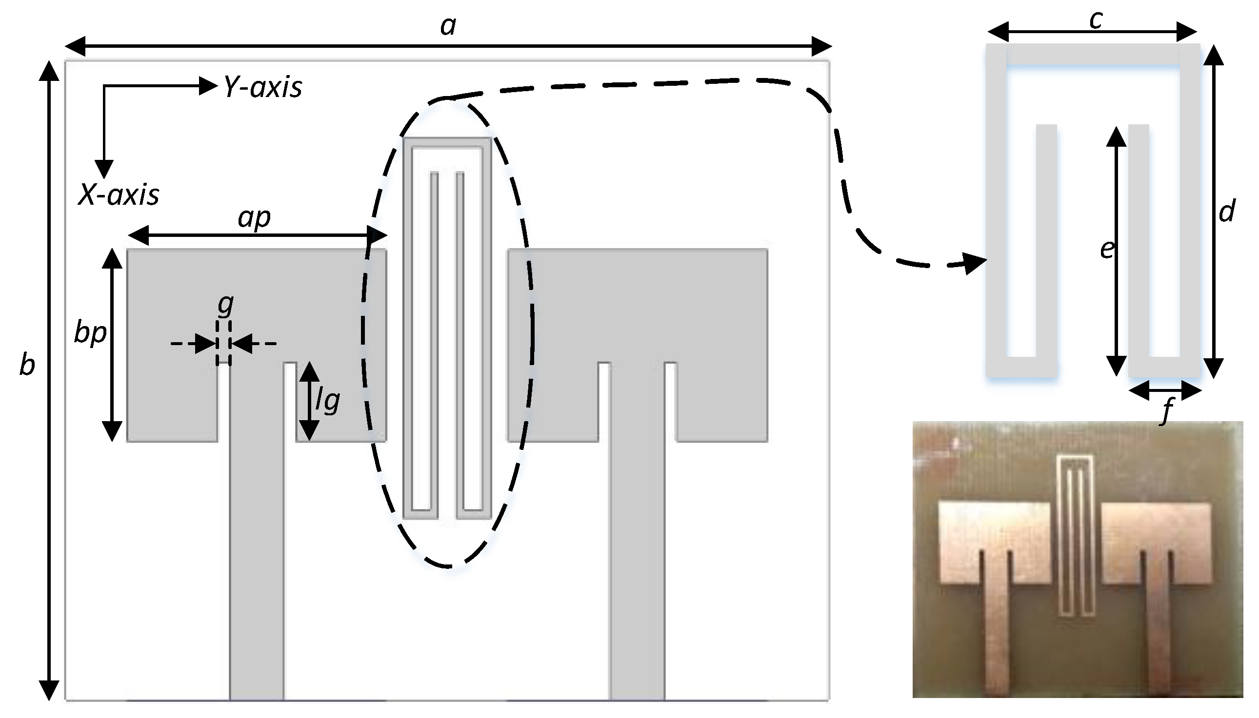
2. Design Methodology
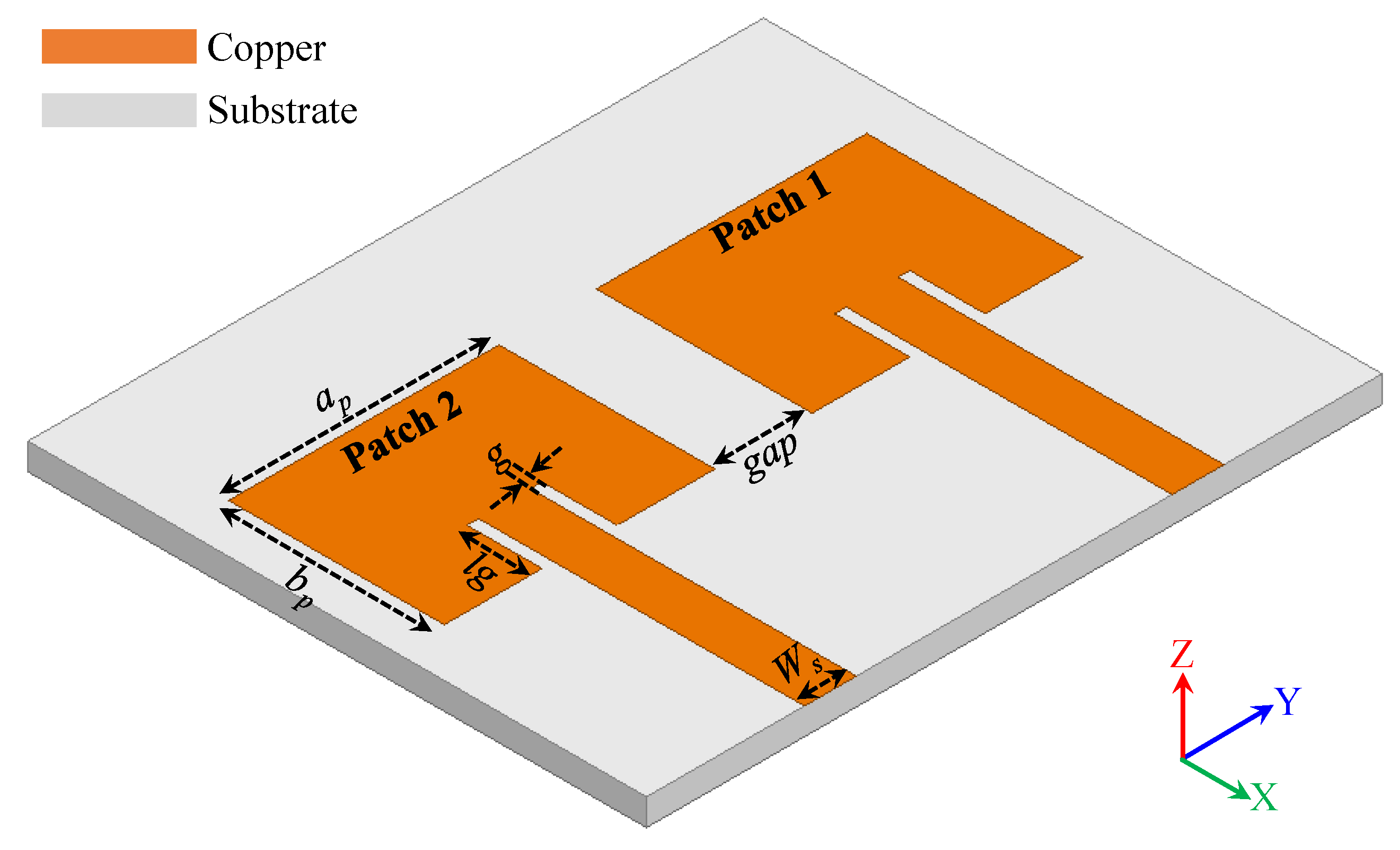
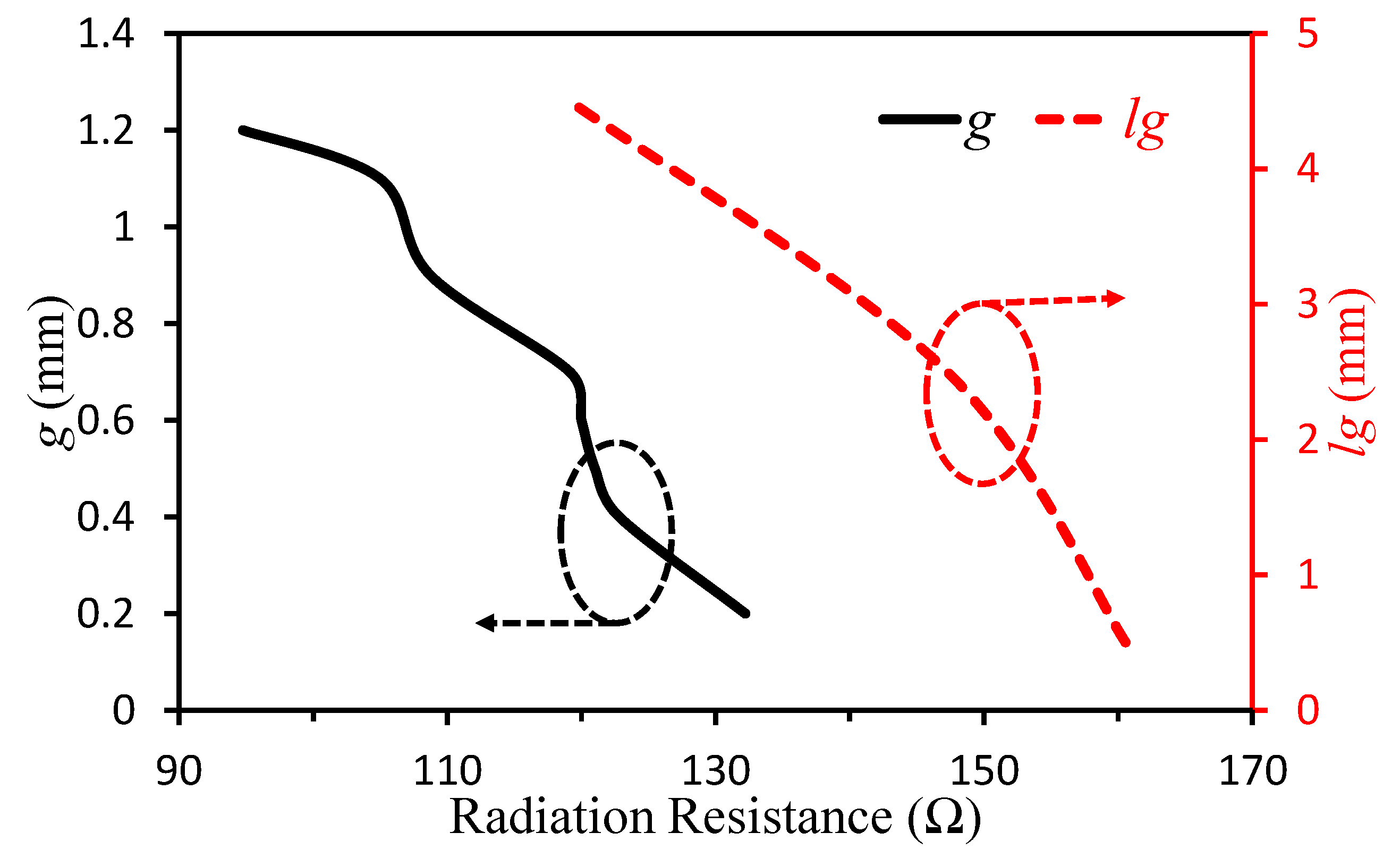
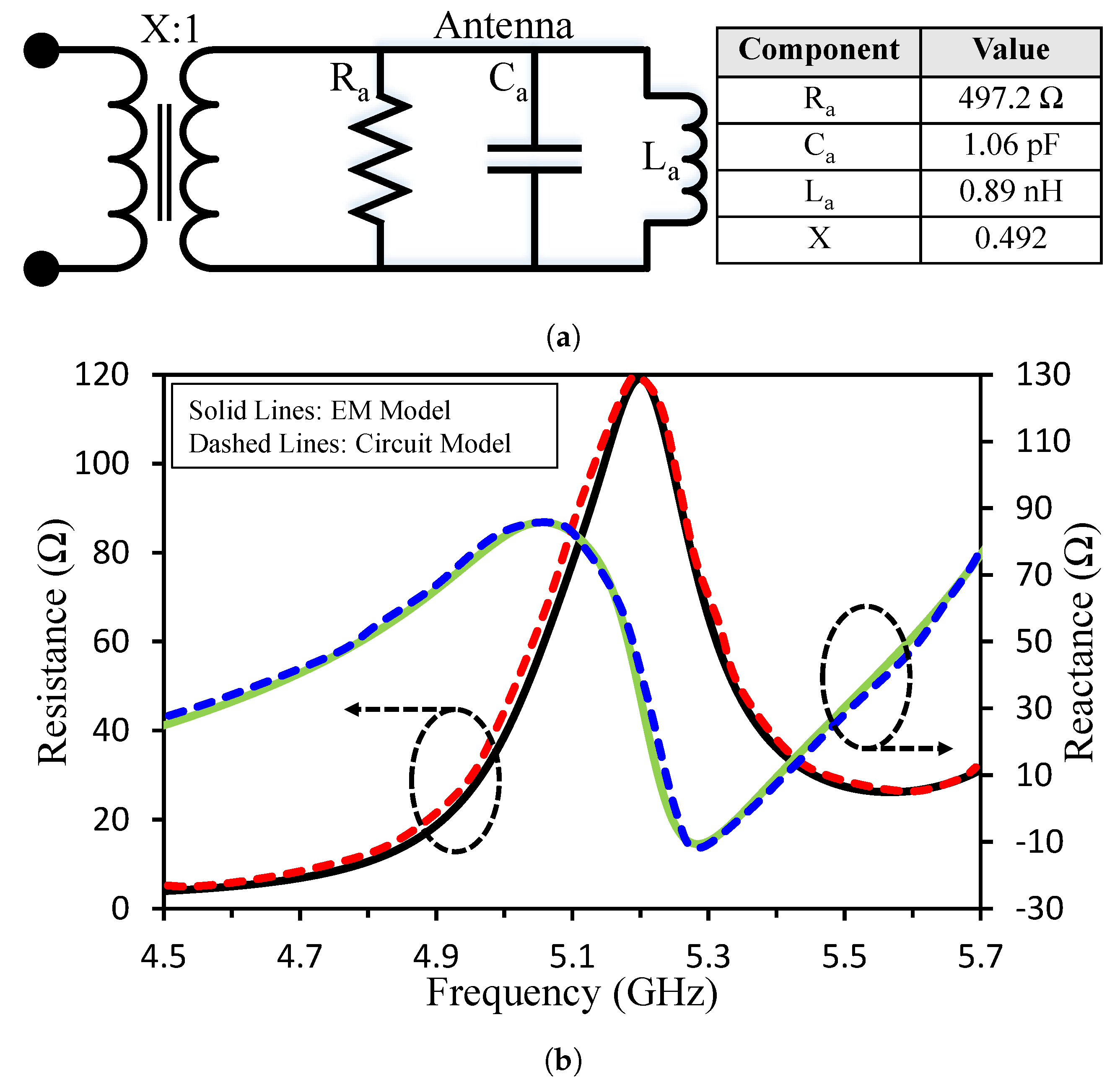
The proposed MIMO antenna is printed on an FR4 substrate with relative permittivity of 4.4 and a thickness of 1.6 mm. A unit antenna is designed by using standard equations [31] at a resonance frequency of 5.4 GHz and is transformed into MIMO separated at less than half-wavelength apart. The proposed antenna is excited through a 50 Ω transmission line having 3.1 mm width. Figure 1 shows geometry of the proposed MIMO Antenna. The design dimensions of proposed antenna are: a p = 16.8 mm, b p = 12.91 mm, g a p = 5.82 mm, W s = 3.1 mm, g = 0.7 mm, and l g = 4.5 mm.
The radiation resistance of an antenna plays a vital role in the performance of the antenna. It is one of the key performance elements of the antenna. The study of radiation resistance of the antenna as a function of inset feeding width (g) and length (lg) is presented in Figure 2. It is observed that by increasing the feeding width (g), the radiation resistance decreased. Similarly, radiation resistance decreased as we increased the length (lg) of the inset feed.

2.1. Unit Antenna

The electrical model is helpful to understand the operating of the antenna in terms of equivalent lump elements for better illustration. From the open literature presented in [28,32,33], a resonator can be modelled as a parallel RLC circuit. Using the same theory, a single element equivalent circuit model is designed. The patch antenna is approximated by an RLC circuit, where R is the radiation resistance of the radiating mode of the antenna, and L and C describe the resonant circuit that are responsible for the desired resonant frequency. The circuit model of the antenna system based on the circuit theory is shown in Figure 3a. The transmission line is modelled as an impedance transformer with the coupling ratio of X:1 in the circuit model. The equivalent circuit model was optimized in Keysight Advance Design System (ADS). The values of each component in the circuit model are depicted in the Figure 3a. The results obtained from the circuit model are verified with the full-wave simulation analysis, as shown in Figure 3b. We observed a close match between the input impedance result of both circuit.

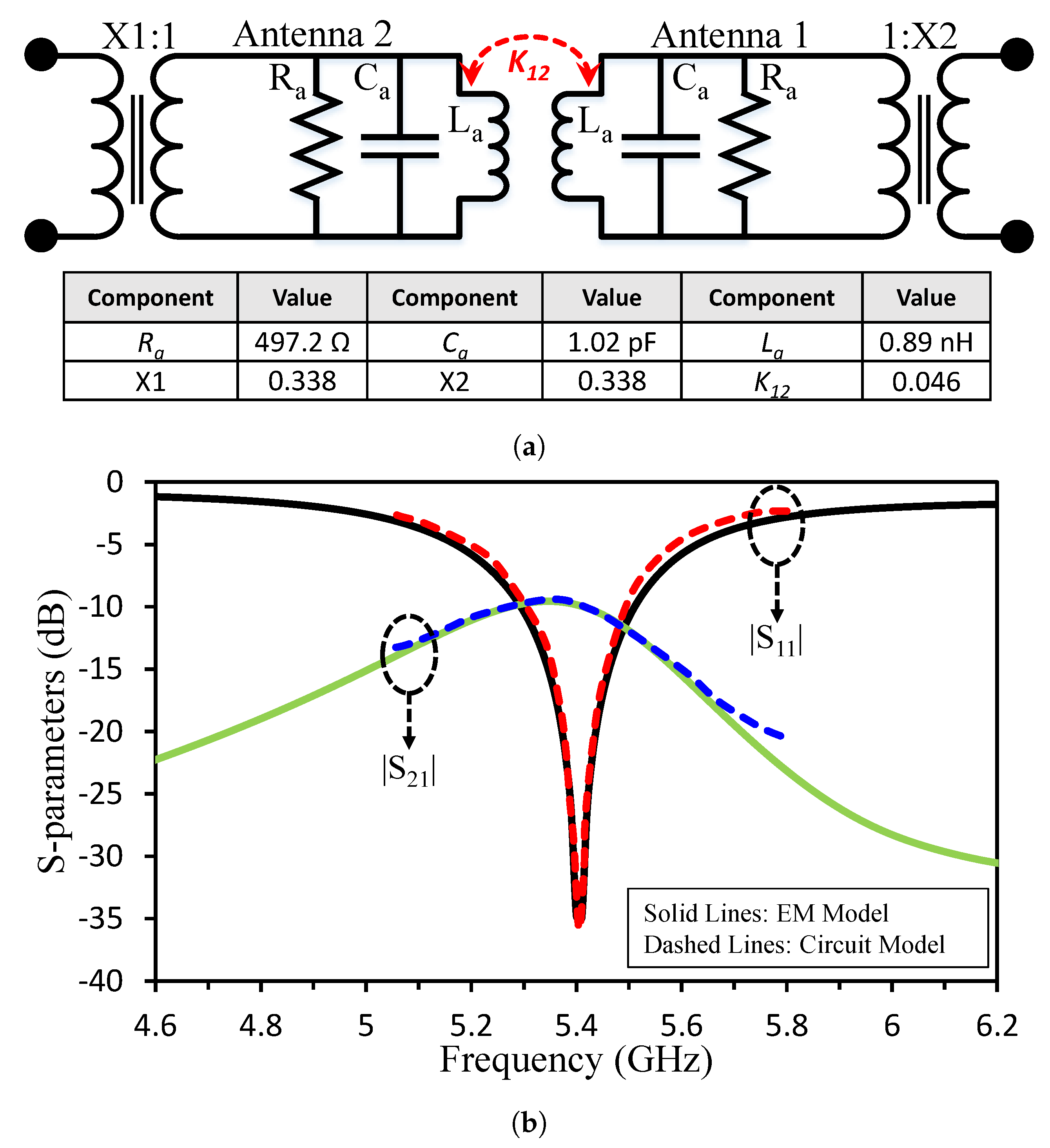
2.2. MIMO Antenna without Decoupling Structure

In this section, the coupling behavior of the antenna elements is analyzed in detail with the exact electrical model description. The main challenge for the MIMO antenna is port isolation or low mutual coupling due to the integration of multiple radiating elements on the small footprint area of the printed circuit board. The two main phenomena namely surface wave propagation inside the substrate and space wave propagation related to near-field/reactive coupling contributes to a large extent in the coupled patch antennas [34]. The after-mentioned limiting factors for MIMO antenna ports isolation can be easily understand via coupled-resonator theory with equivalent resonant circuits.
As mentioned above, the resonators can be represented in the RLC parallel circuit. The circuit model of a two-element MIMO antenna without a decoupling network is presented in Figure 4a. As discussed earlier, the antenna patches and the two transmission lines are modelled using RLC circuits and impedance transformers, respectively. The details of each component are depicted in the table. The coupling depends on the distance between the antenna elements. Since the two antenna elements are near, they are coupled, and the coupling is represented by coupling coefficient ( K 12 ) which is calculated as given in [35]. Strong reactive coupling of around -9 dB within the desired bandwidth is observed. An excellent agreement between the computed circuit model results with the full-wave analysis results is shown in Figure 4b.

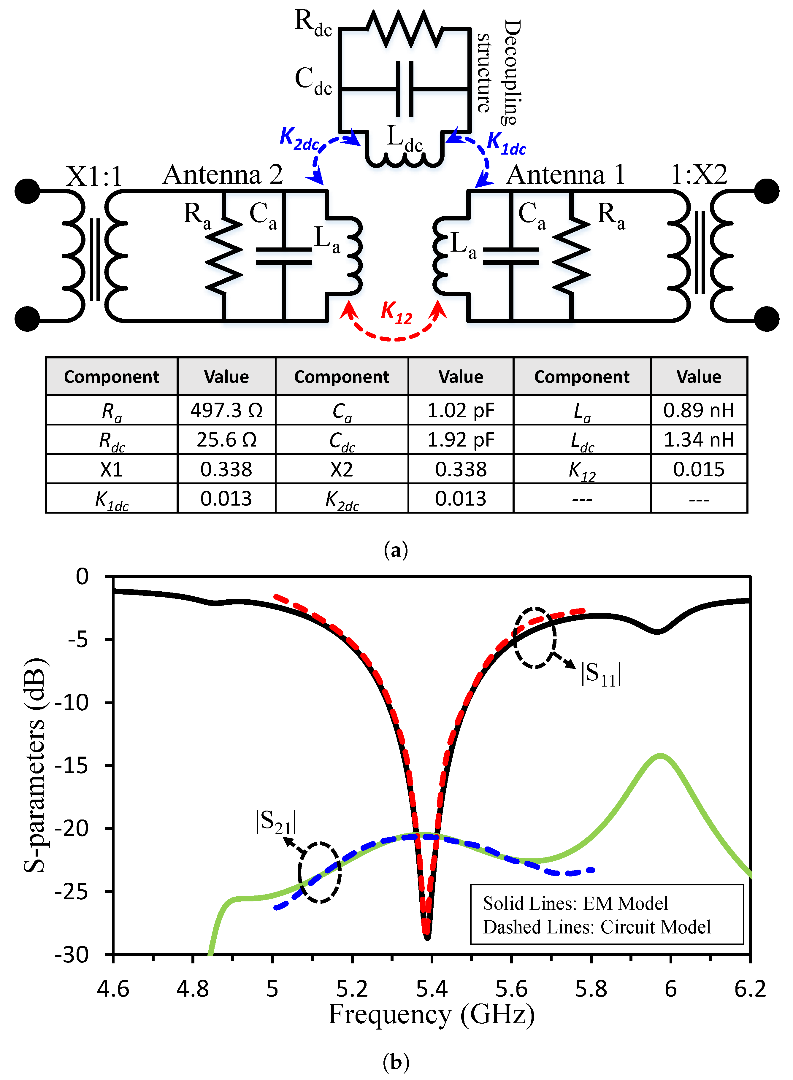
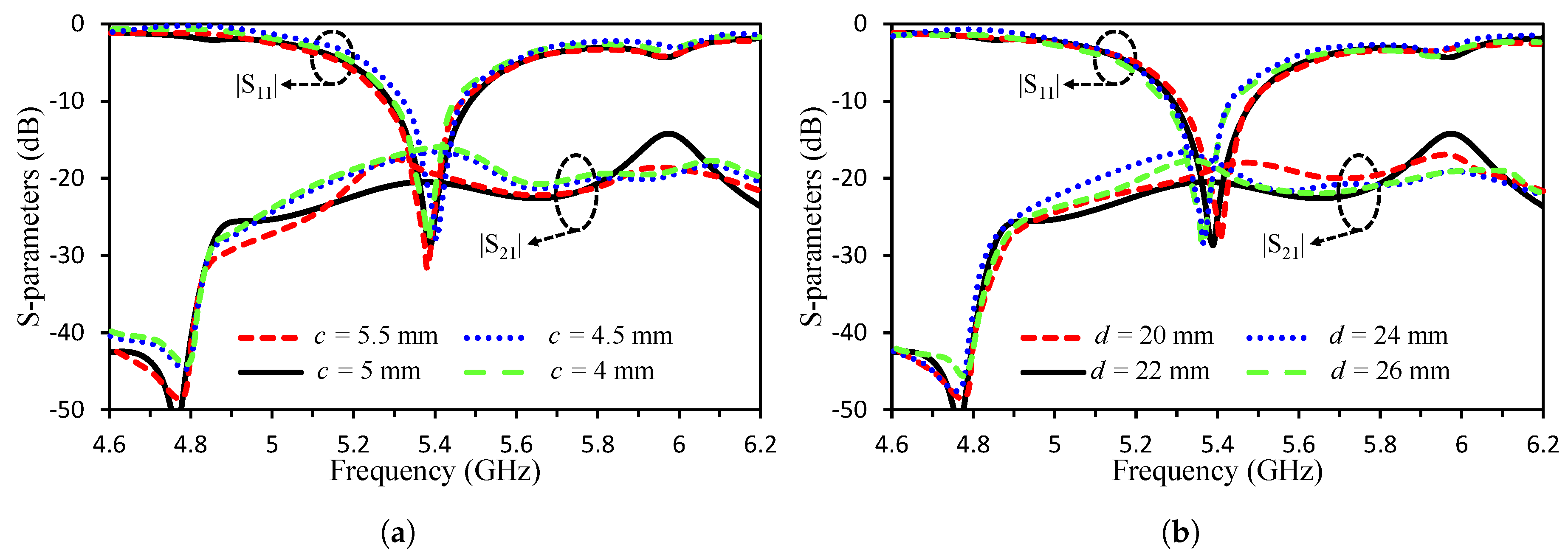
2.3. MIMO Antenna with Decoupling Structure

A novel shaped decoupling structure is used to eliminate the coupling between the MIMO antennas as shown in Figure 5. The dimensions of the decoupling structure are as c = 5 mm, d = 22 mm, e = 20 mm, and f = 2 mm. After the insertion of the decoupling structure, the isolation of −23 dB for the MIMO antenna is accomplished.
The circuit model of a two-element MIMO antenna with a decoupling network is presented in Figure 6a. A parallel combination of RLC is used as a decoupling network, and impedance transformers and RLC circuits are used to model two transmission lines and the antenna patches respectively. The values of each component in the design are depicted in the table. The coupling between the antenna elements is reduced by generating a modified U-shaped resonator, which in turn suppress the undesirable coupling in the frequency range. By the introduction of a modified U-shaped resonator, a strong coupling between the antenna elements is suppressed and a high reduction of coupling around −23 dB is achieved. The validation of the circuit model with the EM analysis is shown in Figure 6b.
We performed many simulations to show the impact of decoupling structure’s dimensions on the reflection and mutual coupling of the antenna. Initially, parameter c was analysed between 4 and 5.5 mm. The parametric analysis of c is shown in Figure 7a. The mutual coupling between the MIMO elements increased when the value of c was reduced or increased from 5 mm. The resonant frequency of the antenna remained unchanged. If we compare the results with circuit model of the decoupling structure, it can be observed that parameter c mainly contribute in K 1 d c and K 2 d c and has small impact on R d c , C d c and L d c . The parametric analysis of d is shown in Figure 7b. We see that the coupling value is inconsistent with variation in d. Analysing the results in context of circuit model, it can be noted that parameter d has impact on K 1 d c and K 2 d c as well as on R d c , C d c and L d c .

3. MIMO Parameters

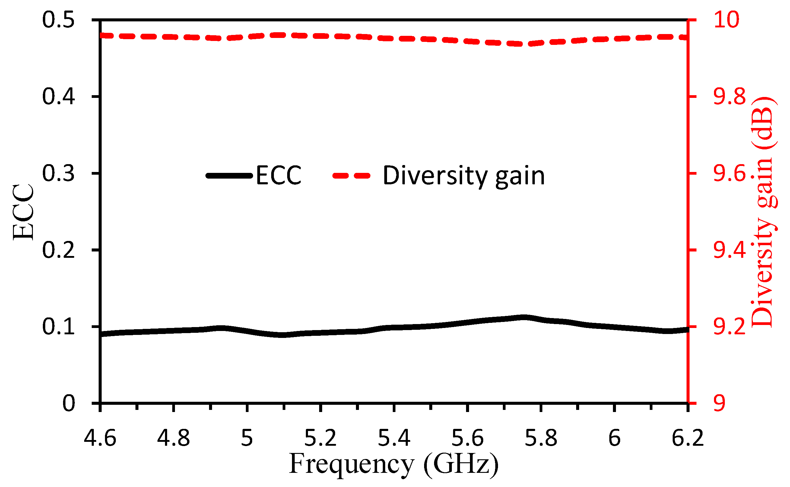
3.1. Envelop Correlation Coefficient (ECC) and Diversity Gain (DG)

Envelop Correlation Coefficient (ECC) and Diversity Gain (DG) are the important MIMO antenna parameters. ECC is the measure of how well antennas are correlated to each other in terms of performance characteristics like return loss and far-field results while diversity gain is the selection of strongest signal for N number of signals. The ECC can be calculated using S-parameters (see Equation (1)) or far-field patterns (see Equation (2)). We calculated the ECC using far field. The ECC and DG are calculated using the following formula given in [11].
E C C = | S 11 * S 12 + S 22 * S 21 | 2 [ 1 ( | S 11 | 2 + | S 12 | 2 ) ] [ 1 ( | S 22 | 2 + | S 21 | 2 ) ]
E C C = | 4 π ( B i ( θ , ϕ ) ) × ( B j ( θ , ϕ ) ) d Ω | 2 4 π | ( B i ( θ , ϕ ) ) | 2 d Ω 4 π | ( B j ( θ , ϕ ) ) | 2 d Ω
where S 11 / S 22 and S 21 / S 12 are the reflection and transmission coefficient of the antenna. B i ( θ , ϕ ) is the three dimensional radiation pattern upon excitation of the ith antenna and B j ( θ , ϕ ) is the three dimensional radiation pattern upon excitation of the jth antenna. Ω represents the solid angle.
D G = 10 1 ( E C C ) 2
The ECC and DG of the MIMO Antenna after the insertion of the proposed isolating structure is given in Figure 8. From the figure, it can be seen that ECC based on far-field results is less than 0.1 and DG is 9.95 dBi at 5.4 GHz with greater than 9.94 dB value for a complete band of interest.

3.2. Channel Capacity Loss (CCL)

The channel capacity loss (CCL) is an important parameter of MIMO antenna. From Figure 9, it can be seen from simulated and measured results that CCL value is equal to 0.07 at 5.4 GHz and less than 0.09 in the whole operating band.

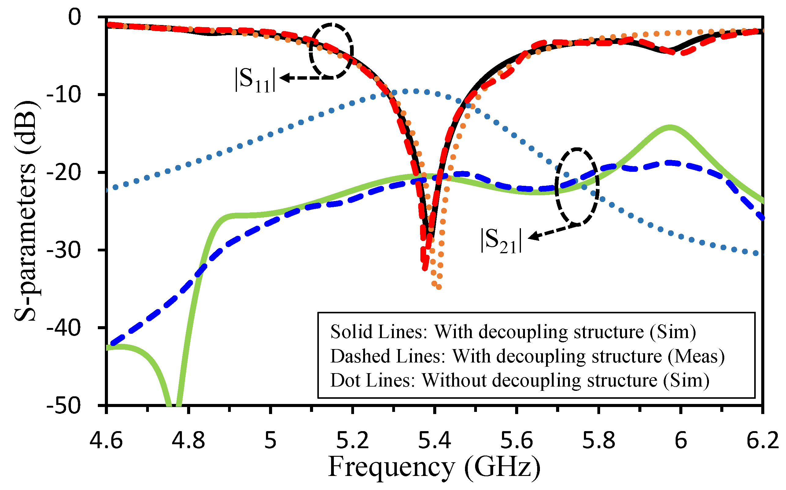
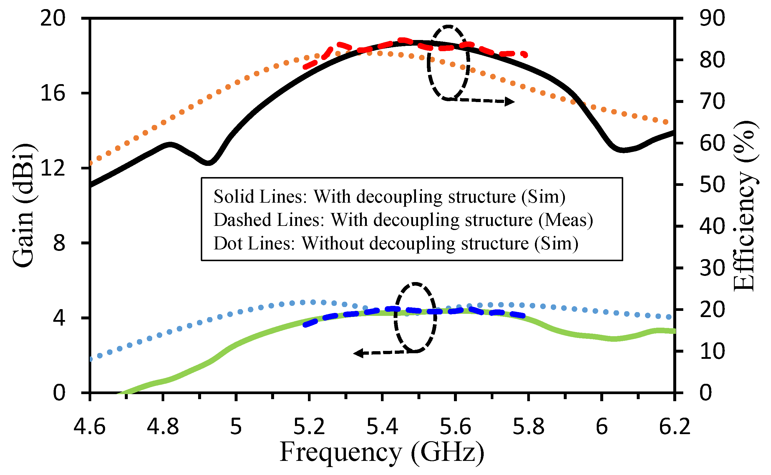
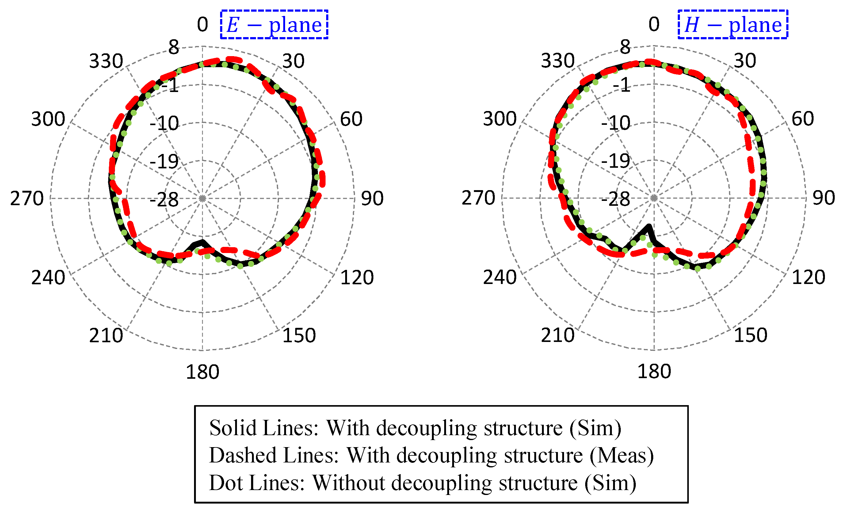
4. Results and Discussions

Surface currents distribution explains the performance analysis of isolating structure over the desired frequency band. Figure 10 shows the current distribution of the MIMO antenna with and without decoupling structure. From Figure 10, it is clear that without the proposed decoupling structure the currents from one antenna upon excitation is seen with high concentrations to another, consequentially leading in high coupling levels whereas with the insertion of decoupling structure, the concentration of currents is focused on the edges of the decoupling structure, resulting in higher isolation.
The proposed antenna was designed and simulated in ANSYS HFSS and was fabricated and tested. The Reflection coefficient and isolation level parameters of the two-port MIMO antenna were measured using a Vector Network Analyzer (VNA) and the radiation patterns were measured in an anechoic chamber. The VNA was calibrated using calibration kit and the two antennas were connected with the two ports for S-parameter measurements. The simulated and measured results were in slightly shift which can be due to cable and environmental losses and errors. Figure 11 shows the simulated and measured S parameters of the MIMO antenna with a decoupling structure as well as simulated S parameters without decoupling structure. It can be seen from the figure that after the insertion of decoupling structure the isolation improvement of more than 14 dB is achieved. We can observe that the reflection coefficient of the MIMO antenna with and without decoupling element is same.
The antenna efficiency and maximum gain over frequency are given in Figure 12. The gain of two-port MIMO antenna with and without decoupling structure is 4.24 dBi and 4.25 dBi, respectively at 5.4 GHz and greater than 4.24 in the whole operating band. Similarly, the efficiency of the MIMO antenna is 81.2% at 5.4 GHz and >80.8% in the whole operating band without decoupling structure. With decoupling structure, the efficiency was 82.4% at 5.4 GHz and >81.1% in the whole operating band. The results shows that the efficiency and gain of the antenna parameters have not been affected after the isolation enhancement.
The radiation patterns of the antenna in two main planes were measured inside an anechoic chamber. One port of the antenna was connected with spectrum analyser and the second port was terminated with a 50 Ω load. A high gain horn antenna was used as a transmitter. The simulated and measured radiation patterns of the proposed MIMO antenna are shown in Figure 13. The Elevation and Azimuth (E and H) plane patterns are slightly misaligned as compared to simulated results which can be justified due to environmental losses and errors. However, it can be observed that the radiation patterns both in E and H planes have remained the same before and after the insertion of the decoupling structure. The proposed system has uni-directional radiation pattern with high front to back ratio of 22.1 dB at 5.4 GHz.
A comparison between our proposed antenna and other antennas is listed in Table 1. It can be observed that the proposed antenna has advantages over existing antennas in terms of small size of decoupling structure, lower edge to edge distance, high FTBR value, lower ECC and CCL values. The high FTBR value of the antenna make this structure suitable for beam scanning and other applications where high directivity is required.

5. Conclusions

We presented a simple and efficient technique to reduce the mutual coupling between nearly packed MIMO elements. We used a modified U-shaped resonator as decoupling structure between the MIMO elements to reduce the undesired associated coupling between them. The MIMO elements were kept at a distance of λ /10 (edge to edge) and the coupling suppression of 14 dB was achieved. The coupling behaviour of the MIMO elements was studied using coupled resonator theory. The proposed system has uni-directional radiation pattern with high front to back ratio of 22.1 dB at 5.4 GHz.

Author Contributions

Design and concept, A.I.; methodology, A.I., A.A. and M.A. (Mujeeb Abdullah); investigation, A.I.; resources, A.I. and S.K.; writing—original draft preparation, A.I., A.A. and M.A. (Mujeeb Abdullah); writing—review and editing, A.I., A.A., M.A. (Mujeeb Abdullah), M.A. (Mohammad Alibakhshikenari), E.L. and S.K.; validation, A.I., A.A., M.A. (Mujeeb Abdullah), M.A. (Mohammad Alibakhshikenari), E.L. and S.K.; supervision, M.A. (Mohammad Alibakhshikenari), E.L. and S.K.; project administration, M.A. (Mohammad Alibakhshikenari), E.L. and S.K. All authors have read and agreed to the published version of the manuscript.

Funding

Following are results of a study on the “Leaders in INdustry-university Cooperation +” Project, supported by the Ministry of Education and National Research Foundation of Korea.

Conflicts of Interest

The authors declare no conflict of interest.

References

  1. Abdullah, M.; Kiani, S.H.; Abdulrazak, L.F.; Iqbal, A.; Bashir, M.; Khan, S.; Kim, S. High-performance multiple-input multiple-output antenna system for 5G mobile terminals. Electronics 2019, 8, 1090. [Google Scholar] [CrossRef] [Green Version]
  2. Abdullah, M.; Kiani, S.H.; Iqbal, A. Eight element multiple-input multiple-output (MIMO) antenna for 5G mobile applications. IEEE Access 2019, 7, 134488–134495. [Google Scholar] [CrossRef]
  3. Iqbal, A.; Saraereh, O.A.; Ahmad, A.W.; Bashir, S. Mutual coupling reduction using F-shaped stubs in UWB-MIMO antenna. IEEE Access 2017, 6, 2755–2759. [Google Scholar] [CrossRef]
  4. Acharjee, J.; Mandal, K.; Mandal, S.K. Reduction of mutual coupling and cross-polarization of a MIMO/diversity antenna using a string of H-shaped DGS. AEU-Int. J. Electron. Commun. 2018, 97, 110–119. [Google Scholar] [CrossRef]
  5. Sindhadevi, M.; Malathi, K.; Henridass, A.; Shrivastav, A.K. Signal integrity performance analysis of mutual coupling reduction techniques using DGS in high speed printed circuit boards. Wirel. Pers. Commun. 2017, 94, 3233–3249. [Google Scholar] [CrossRef]
  6. Liu, Y.; Yang, X.; Jia, Y.; Guo, Y.J. A low correlation and mutual coupling MIMO antenna. IEEE Access 2019, 7, 127384–127392. [Google Scholar] [CrossRef]
  7. OuYang, J.; Yang, F.; Wang, Z. Reducing mutual coupling of closely spaced microstrip MIMO antennas for WLAN application. IEEE Antennas Wirel. Propag. Lett. 2011, 10, 310–313. [Google Scholar] [CrossRef]
  8. Altaf, A.; Alsunaidi, M.A.; Arvas, E. A novel EBG structure to improve isolation in MIMO antenna. In Proceedings of the 2017 USNC-URSI Radio Science Meeting (Joint with AP-S Symposium), San Diego, CA, USA, 9–14 July 2017; pp. 105–106. [Google Scholar]
  9. Yu, A.; Zhang, X. A novel method to improve the performance of microstrip antenna arrays using a dumbbell EBG structure. IEEE Antennas Wirel. Propag. Lett. 2003, 2, 170–172. [Google Scholar]
  10. Farahani, H.S.; Veysi, M.; Kamyab, M.; Tadjalli, A. Mutual coupling reduction in patch antenna arrays using a UC-EBG superstrate. IEEE Antennas Wirel. Propag. Lett. 2010, 9, 57–59. [Google Scholar] [CrossRef]
  11. Iqbal, A.; A Saraereh, O.; Bouazizi, A.; Basir, A. Metamaterial-based highly isolated MIMO antenna for portable wireless applications. Electronics 2018, 7, 267. [Google Scholar] [CrossRef] [Green Version]
  12. Iqbal, A.; Basir, A.; Smida, A.; Mallat, N.K.; Elfergani, I.; Rodriguez, J.; Kim, S. Electromagnetic bandgap backed millimeter-wave MIMO antenna for wearable applications. IEEE Access 2019, 7, 111135–111144. [Google Scholar] [CrossRef]
  13. Ullah, S.; Yeo, W.H.; Kim, H.; Yoo, H. Development of 60-GHz millimeter wave, electromagnetic bandgap ground planes for multiple-input multiple-output antenna applications. Sci. Rep. 2020, 10, 1–12. [Google Scholar] [CrossRef] [PubMed]
  14. Habashi, A.; Nourinia, J.; Ghobadi, C. Mutual coupling reduction between very closely spaced patch antennas using low-profile folded split-ring resonators (FSRRs). IEEE Antennas Wirel. Propag. Lett. 2011, 10, 862–865. [Google Scholar] [CrossRef]
  15. Lee, J.Y.; Kim, S.H.; Jang, J.H. Reduction of mutual coupling in planar multiple antenna by using 1-D EBG and SRR structures. IEEE Trans. Antennas Propag. 2015, 63, 4194–4198. [Google Scholar] [CrossRef]
  16. Hafezifard, R.; Naser-Moghadasi, M.; Mohassel, J.R.; Sadeghzadeh, R. Mutual coupling reduction for two closely spaced meander line antennas using metamaterial substrate. IEEE Antennas Wirel. Propag. Lett. 2015, 15, 40–43. [Google Scholar]
  17. Ghosh, J.; Ghosal, S.; Mitra, D.; Bhadra Chaudhuri, S.R. Mutual coupling reduction between closely placed microstrip patch antenna using meander line resonator. Prog. Electromagn. Res. 2016, 59, 115–122. [Google Scholar] [CrossRef] [Green Version]
  18. Babu, K.V.; Anuradha, B. Design of Wang shape neutralization line antenna to reduce the mutual coupling in MIMO antennas. Analog Integr. Circuits Signal Process. 2019, 101, 67–76. [Google Scholar] [CrossRef]
  19. Vishvaksenan, K.S.; Mithra, K.; Kalaiarasan, R.; Raj, K.S. Mutual coupling reduction in microstrip patch antenna arrays using parallel coupled-line resonators. IEEE Antennas Wirel. Propag. Lett. 2017, 16, 2146–2149. [Google Scholar] [CrossRef]
  20. Luan, H.; Chen, C.; Chen, W.; Zhou, L.; Zhang, H.; Zhang, Z. Mutual Coupling Reduction of Closely E/H-Plane Coupled Antennas Through Metasurfaces. IEEE Antennas Wirel. Propag. Lett. 2019, 18, 1996–2000. [Google Scholar] [CrossRef]
  21. Khalid, M.; Iffat Naqvi, S.; Hussain, N.; Rahman, M.; Fawad; Mirjavadi, S.S.; Khan, M.J.; Amin, Y. 4-Port MIMO antenna with defected ground structure for 5G millimeter wave applications. Electronics 2020, 9, 71. [Google Scholar] [CrossRef] [Green Version]
  22. Sehrai, D.A.; Abdullah, M.; Altaf, A.; Kiani, S.H.; Muhammad, F.; Tufail, M.; Irfan, M.; Glowacz, A.; Rahman, S. A Novel High Gain Wideband MIMO Antenna for 5G Millimeter Wave Applications. Electronics 2020, 9, 1031. [Google Scholar] [CrossRef]
  23. Iqbal, A.; Smida, A.; Alazemi, A.J.; Waly, M.I.; Mallat, N.K.; Kim, S. Wideband Circularly Polarized MIMO Antenna for High Data Wearable Biotelemetric Devices. IEEE Access 2020, 8, 17935–17944. [Google Scholar] [CrossRef]
  24. Kumar, P.; Urooj, S.; Alrowais, F. Design of quad-port MIMO/Diversity antenna with triple-band elimination characteristics for super-wideband applications. Sensors 2020, 20, 624. [Google Scholar] [CrossRef] [PubMed] [Green Version]
  25. Mohamadzade, B.; Lalbakhsh, A.; Simorangkir, R.B.; Rezaee, A.; Hashmi, R.M. Mutual Coupling Reduction in Microstrip Array Antenna by Employing Cut Side Patches and EBG Structures. Prog. Electromagn. Res. 2020, 89, 179–187. [Google Scholar] [CrossRef] [Green Version]
  26. Margaret, D.H.; Subasree, M.; Susithra, S.; Keerthika, S.; Manimegalai, B. Mutual coupling reduction in MIMO antenna system using EBG structures. In Proceedings of the 2012 International Conference on Signal Processing and Communications (SPCOM), Bangalore, India, 22–25 July 2012; pp. 1–5. [Google Scholar]
  27. Si, L.; Jiang, H.; Lv, X.; Ding, J. Broadband extremely close-spaced 5G MIMO antenna with mutual coupling reduction using metamaterial-inspired superstrate. Opt. Express 2019, 27, 3472–3482. [Google Scholar] [CrossRef] [PubMed]
  28. Wei, K.; Li, J.Y.; Wang, L.; Xing, Z.J.; Xu, R. Mutual coupling reduction by novel fractal defected ground structure bandgap filter. IEEE Trans. Antennas Propag. 2016, 64, 4328–4335. [Google Scholar] [CrossRef]
  29. Kiani, S.H.; Mahmood, K.; Altaf, A.; Cole, A.J. Mutual coupling reduction of MIMO antenna for satellite services and radio altimeter applications. Int. J. Adv. Comput. Sci. Appl. 2018, 9, 23–26. [Google Scholar] [CrossRef] [Green Version]
  30. Arun, H.; Sarma, A.K.; Kanagasabai, M.; Velan, S.; Raviteja, C.; Alsath, M.G.N. Deployment of modified serpentine structure for mutual coupling reduction in MIMO antennas. IEEE Antennas Wirel. Propag. Lett. 2014, 13, 277–280. [Google Scholar] [CrossRef]
  31. Balanis, C.A. Antenna Theory: Analysis and Design; John Wiley & Sons: Hoboken, NJ, USA, 2016. [Google Scholar]
  32. Iqbal, A.; Selmi, M.A.; Abdulrazak, L.F.; Saraereh, O.A.; Mallat, N.K.; Smida, A. A Compact Substrate Integrated Waveguide Cavity-Backed Self-Triplexing Antenna. IEEE Trans. Circuits Syst. II Express Briefs 2020. [Google Scholar] [CrossRef]
  33. Elfergani, I.; Iqbal, A.; Zebiri, C.; Basir, A.; Rodriguez, J.; Sajedin, M.; Pereira, A.D.O.; Mshwat, W.; Abd-Alhameed, R.; Ullah, S. Low-Profile and Closely Spaced Four-Element MIMO Antenna for Wireless Body Area Networks. Electronics 2020, 9, 258. [Google Scholar] [CrossRef] [Green Version]
  34. Farahani, M.; Pourahmadazar, J.; Akbari, M.; Nedil, M.; Sebak, A.R.; Denidni, T.A. Mutual coupling reduction in millimeter-wave MIMO antenna array using a metamaterial polarization-rotator wall. IEEE Antennas Wirel. Propag. Lett. 2017, 16, 2324–2327. [Google Scholar] [CrossRef]
  35. Qamar, Z.; Naeem, U.; Khan, S.A.; Chongcheawchamnan, M.; Shafique, M.F. Mutual coupling reduction for high-performance densely packed patch antenna arrays on finite substrate. IEEE Trans. Antennas Propag. 2016, 64, 1653–1660. [Google Scholar] [CrossRef]
Figure 1. Geometry of the initially designed MIMO antenna ( a p = 16.8, b p = 12.91, g a p = 5.82, W s = 3.1, g = 0.7, and l g = 4.5 [unit = mm]).
Electronics 09 01321 g001
Figure 2. Radiation resistance of the antenna with varying g (when lg = 4.5 mm) and lg (when g = 0.7 mm).
Electronics 09 01321 g002
Figure 3. (a) Equivalent circuit model of the single-unit antenna, and (b) input impedance (resistance and reactance) comparison of the EM model (solid lines) and circuit model (dashed lines).
Electronics 09 01321 g003
Figure 4. (a) Equivalent circuit model of the two-element MIMO antenna without decoupling structure, and (b) S-parameters comparison of the EM model (solid lines) and circuit model (dashed lines).
Electronics 09 01321 g004
Figure 5. Geometry of the proposed MIMO antenna with decoupling structure ( a p = 16.8, b p = 12.91, W s = 3.1, g = 0.7, and l g = 7, a = 44, b = 37, c = 5, d = 22, e = 20, f = 2 [unit = mm]) and fabricated prototype.
Electronics 09 01321 g005
Figure 6. (a) Equivalent circuit model of the two-element MIMO antenna with decoupling structure, and (b) S-parameters comparison of the EM model (solid lines) and circuit model (dashed lines).
Electronics 09 01321 g006
Figure 7. Parametric analysis of the decoupling structure by varying (a) c and (b) d.
Electronics 09 01321 g007
Figure 8. ECC and diversity gain of the antenna.
Electronics 09 01321 g008
Figure 9. Simulated and measured CCL of the antenna in the presence of decoupling structure.
Electronics 09 01321 g009
Figure 10. Surface current distribution of the antenna at 5.4 GHz in the presence and absence of decoupling structure.
Electronics 09 01321 g010
Figure 11. Simulated (with and without decoupling structure) and measured (with decoupling structure) S-parameters of the antenna.
Electronics 09 01321 g011
Figure 12. Simulated (with and without decoupling structure) and measured (with decoupling structure) gain and efficiency of the antenna.
Electronics 09 01321 g012
Figure 13. Simulated (with and without decoupling structure) and measured (with decoupling structure) radiation pattern (E- and H-plane) of the antenna at 5.4 GHz.
Electronics 09 01321 g013
Table 1. Comparison table (where λ is the wavelength at centre frequency).
Ref.TechniqueCentre Frequency
(GHz)
Edge to Edge
Distance
Isolation
Improvement
FTBR
(dB)
ECCCCL
(bps/Hz)
[7]Slotted ground5.80.33 λ 40NANANA
[9]EBG7.5NA4NANANA
[10]UC-EBG5.560.5 λ 10NANANA
[11]Metamaterial5.80.135 λ 9NA<0.1<0.05
[17]I-shaped
resonator
2.80.056 λ 8–10NANANA
[26]EBG60.5 λ 8NA<0.01NA
[30]Serpentine
structure
2.450.05 λ 10–34NA<0.007NA
[34]metamaterial
polarization-rotator
60NA16NA<0.1 × 10 6 NA
This
Work
U-Shaped
resonator
5.40.1 λ 1422.1<0.10.07

