Article

Efficiency of Cascaded Neural Networks in Detecting Initial Damage to Induction Motor Electric Windings

by
Maciej Skowron
* and
Teresa Orłowska-Kowalska
Department of Electrical Machines, Drives and Measurements, Wroclaw University of Science and Technology, wyb. Wyspianskiego 27, 50-370 Wroclaw, Poland
*
Author to whom correspondence should be addressed.
Electronics 2020, 9(8), 1314; https://doi.org/10.3390/electronics9081314
Submission received: 23 July 2020 / Revised: 12 August 2020 / Accepted: 12 August 2020 / Published: 15 August 2020

Abstract

:
This article presents the efficiency of using cascaded neural structures in the process of detecting damage to electrical circuits in a squirrel cage induction motor (IM) supplied from a frequency converter. The authors present the idea of a sequential connection of classic neural structures to increase the efficiency of damage classification and detection presented by individual neural structures, especially in the initial phase of single or multiple electrical failures. The easily measurable axial flux signal is used as a source of diagnostic information. The developed cascaded neural networks are implemented in the measurement and diagnostic software made in the LabVIEW environment. The results of the experimental research on a 1.5 kW IM supplied by an industrial frequency converter confirm the high efficiency of the use of the developed cascaded neural structures in the detection of incipient stator and rotor winding faults, namely inter-turn stator winding short circuits and broken rotor bars, as well as mixed failures in the entire range of changes of the load torque and supply voltage frequency.

1. Introduction

The ever-growing requirements regarding the quality of production and the efficiency and reliability of industrial equipment make modern industrial systems increasingly complex. Therefore, there is a growing interest in the reliability and diagnostics of the state and failure forecasting for these systems.
Electric machines, in particular induction motors (IM), play an important role in the industry due to their widespread use in propulsion systems. For this reason, the requirements for their reliable and safe operation are constantly increasing [1].
It should be noted that damages to the electric windings of the stator and rotor of an induction motor constitute nearly 50% of all damages encountered in practice [1,2]. Their special feature, especially in the case of failure of the stator windings (~38%), is the avalanche propagation—from short circuits in single turns, through phase short circuits to earth faults, resulting in total machine damage and drive system downtime (and frequently the entire production line). Therefore, the timely detection of the incipient winding damage is an extremely important issue from a technical point of view.
Analytical methods of fault detection require a thorough knowledge of the tested object. The role of humans as experts results in extended analysis time, as well as a lack of automation of the detection process. In order to limit the role of these human experts in fully automated diagnostic systems, artificial intelligence (AI) methods, in particular artificial neural networks (ANN), are increasingly used. Additionally, diagnostics systems for electric machines using neural networks (NN) are currently being widely developed by many scientific centers. The main task of neural structures is the full automation of the technical condition assessment process of an electric motor. Neural networks provide diagnostic information as a response to a given input vector and often complement analytical fault detection methods. Among the neural structures most often used in the diagnostics of electrical machines, the following deserve special attention:
-
multilayer perceptron (MLP),
-
self-organizing Kohonen maps (SOM),
-
networks with radial activation functions (RBF),
-
recursive neural networks (RNN),
-
wavelet neural networks (WNN).
The most frequently used neural structure in the IM diagnostic processes is the multilayer perceptron (MLP). This is due to its simple mathematical description, and thus easy hardware implementation. However, to ensure proper damage detection, the correct selection of the NN structure [3,4,5,6], teaching method [7,8], activation function [8], and network input vector [9] is required. In most MLP network applications in IM diagnostic systems, the network training process is carried out according to the Levenberg–Marquardt (L-M) algorithm [3,8,9] or the backward propagation algorithm (BP) [4,6,8,10]. Despite the simple structure of the MLP network, it has a relatively long learning time. In [8], the influence of the teaching method on the detection efficiency of IM electric and mechanical faults was presented. The authors showed the possibility of using principal component analysis (PCA) to reduce the number of neural connections in MLP networks. Ensuring that the optimal network structure is associated with the appropriate selection of the number of neurons in each of the hidden layers. An analytical approach to structure optimization was used in [4]. The authors presented the effectiveness of selecting the number of hidden layer neurons based on the sizes of the input and output vectors. In [5], the possibility of using a genetic algorithm (GA) to select the appropriate number of neurons in individual layers was presented. Properly selected activation functions [8] and elements of the input vector [6,9] can ensure high detection efficiency with a short time required for network training. In [9], the authors presented the use of network information as an input vector from various diagnostic signal analyses. The approach used in [9] resulted in a significant improvement in the efficiency of the neural detector of motor damage.
Damage classifiers also play a very important role in diagnostic processes. The main representative of neural damage classifiers is the Kohonen self-organizing network (SOM). Possible applications of the SOM in the detection and classification of IM faults are presented in [8,11,12,13,14,15,16], among others. The undoubted advantage of the Kohonen network is the relatively small size of the training vector required to ensure a high efficiency level. SOM is characterized by its simple mathematical description, as well as the short time of the training process, which resulted in the creation of numerous variations of this structure. As in the case of the MLP, the efficiency of the SOM network in IM fault classification is strongly dependent on the structure used. The impacts of the SOM network topology, neighborhood function, as well as the scope of neighborhood, are discussed in [8,16]. In [12], the influence of the number of neurons in the network output layer on the classification effectiveness of electrical rotor faults in IM using SOM was presented.
In addition to the basic MLP and SOM structures discussed here, there is a great deal of interest in the literature on neural networks with radial basis functions (RBF) [17,18,19,20]. The main difference between MLP and RBF is the activation function used in the hidden layer. This difference influences the task of the NN network. In the case of MLP, this is the approximation of the analyzed function, while RBF performs a local approximation, taking into account the cluster of data around the central point. In [18], the authors demonstrated the superiority of the RBF network over MLP in the process of detecting damage to IM electrical circuits. The comparison of the two structures was possible due to the use of the same number of neurons in individual layers, as well as the same learning and testing vector.
Recursive neural networks (RNNs) are also used in diagnostic processes. A characteristic feature of these networks is the presence of feedback loops in their structure. The primary representatives of recursive networks used in the IM diagnostics are the Elman network (ENN) [21,22] and the recursive Hopfield network (RHN) [23,24,25]. The recursive Hopfield network is characterized by associative memory, thanks to which it is mainly used for pattern recognition [23]. The Elman network has a simplified recursion model and is used in the processing of time series [21]. In the IM diagnostic systems, the Elman network is more often used [21,22] due to the applied data processing method. Nevertheless, the associative memory of the Hopfield network is widely used in error recognition systems, e.g., electronic [23] or electromechanical [25] systems.
One previous work [26] presented a comparison of the effectiveness of three types of classic NN structures—MLP, SOM, and RHN—when applied to early damage detection in the stator winding and the IM rotor, based on the analysis of the axial flux signal induced in the measuring coil located on the motor. The results of the effectiveness tests of three different structures of damage detectors, developed using the mentioned NNs, were presented and it was shown that each of them presents specific advantages and disadvantages. All of the analyzed NNs presented quite good results in detection of separate stator or rotor winding faults, however the weakest results for fault detection and classification were obtained in the case of the mixed IM electrical faults.
In the literature from the last 20 years, many hybridization structures for NNs were developed by combining different soft computing paradigms, which offers benefits associated with the advantages of the various techniques considered. These methods can be grouped into three classes:
models—whereby mathematical models of NNs include various typological functions, creating the so-called hybrid neural networks (HNNs), including serial connections of different neural structures,
algorithms—whereby the learning procedure uses traditional and heuristic methods,
data—whereby NNs are obtained from heterogeneous data structures.
All these methods can be effective for a given problem and a set of databases, but none of the methodologies can generally be assessed as the best for all applications [27].
HNNs have also been tested for IM fault detection and classification [28,29,30,31,32]. The first works on the subject concerned the connection of a MLP network with fuzzy logic reasoning. Such a fuzzy hybrid neural network (F-HNN), composed of two subnetworks connected in a cascade—the fuzzy self-organizing layer performing the preclassification task and the following MLP working as the final classifier—was used in [28] for IM bearing damage recognition. The problem of IM fault classification using HNN was raised, among others, in [29,30,31,32].
In [29], a hybrid neural classifier of different IM faults is described, combining the auto-encoder neural network (A-ENN) and the lattice vector quantization (LVQ) model. The A-ENN is used for dimensionality reduction by projecting high-dimensional data into a 2D space. The LVQ model is used for data visualization by forming and adapting the granularity of a data map. The mapped data are employed to predict the target classes of new data samples. The presented results show that the hybrid classifier is more effective in terms of classification accuracy for various IM fault conditions than a classic MLP network. In [30], the authors presented a possible IM defect classification method based on the response of the hybrid structure obtained via the combination of data classifiers and the idea of decision trees operation.
Literature analysis shows that the HNN solutions used are mainly based either on direct analysis of the network output vector using simple response evaluation algorithms or decision trees. However, none of the publications shows the possibility of differentiating damages occurring simultaneously. The use of a combination of several NN structures achieves a high effectiveness level in both deep neural networks [31] and classic neural structures [32].
As stated above, damages to IM electric windings, in particular inter-turn short circuits, are avalanche in nature, and therefore from a technical point of view their detection only makes sense at the initial stage of their development. In addition, the symptoms of these damages strongly depend on the supply voltage frequency and the motor load value. For example, when a motor is lightly loaded, it is extremely difficult to detect damage to the rotor cage. Moreover, the simultaneous occurrence of these faults under light loads makes their classification and detection very difficult.
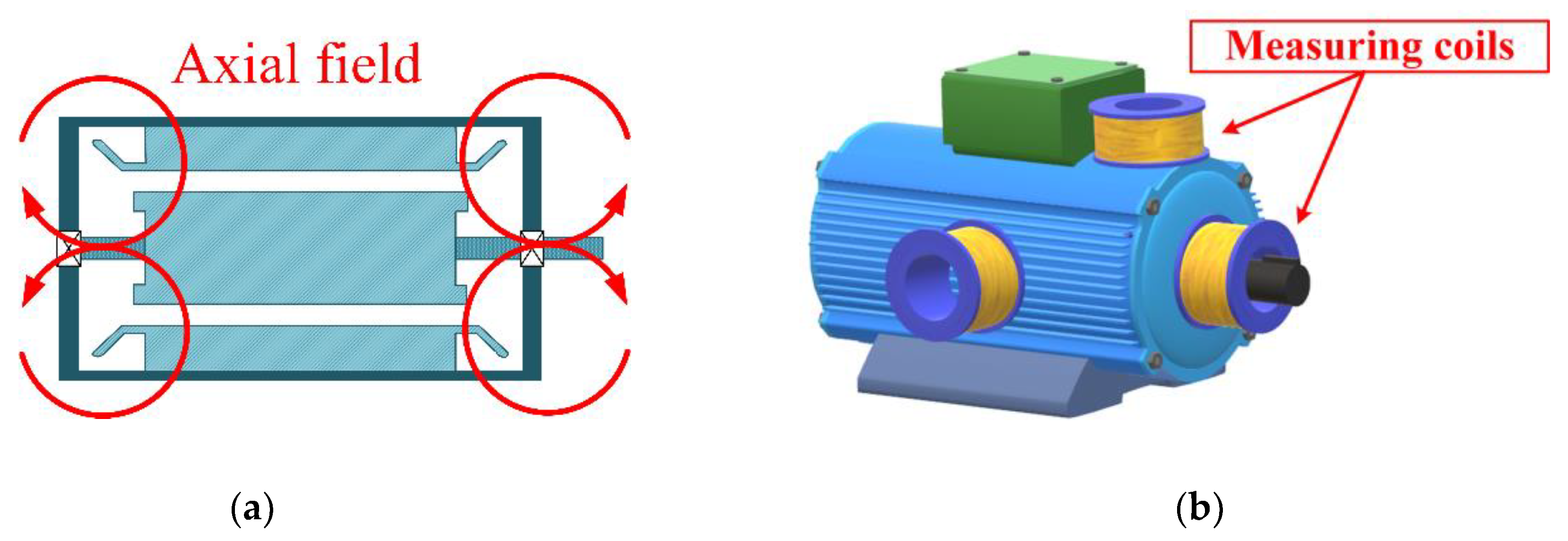
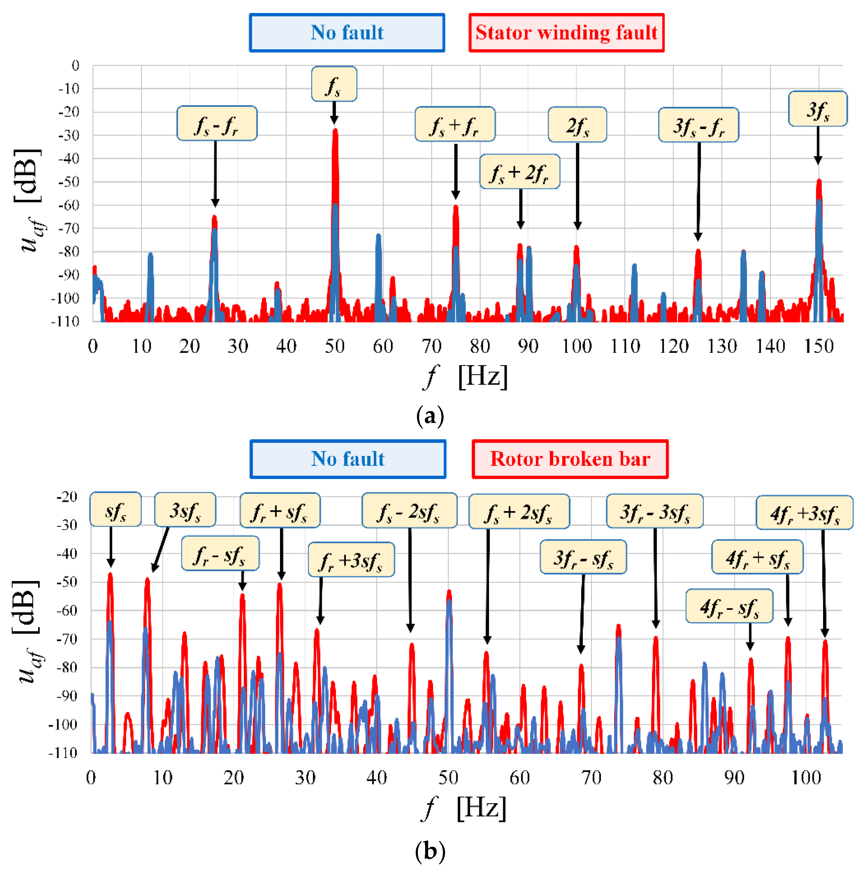
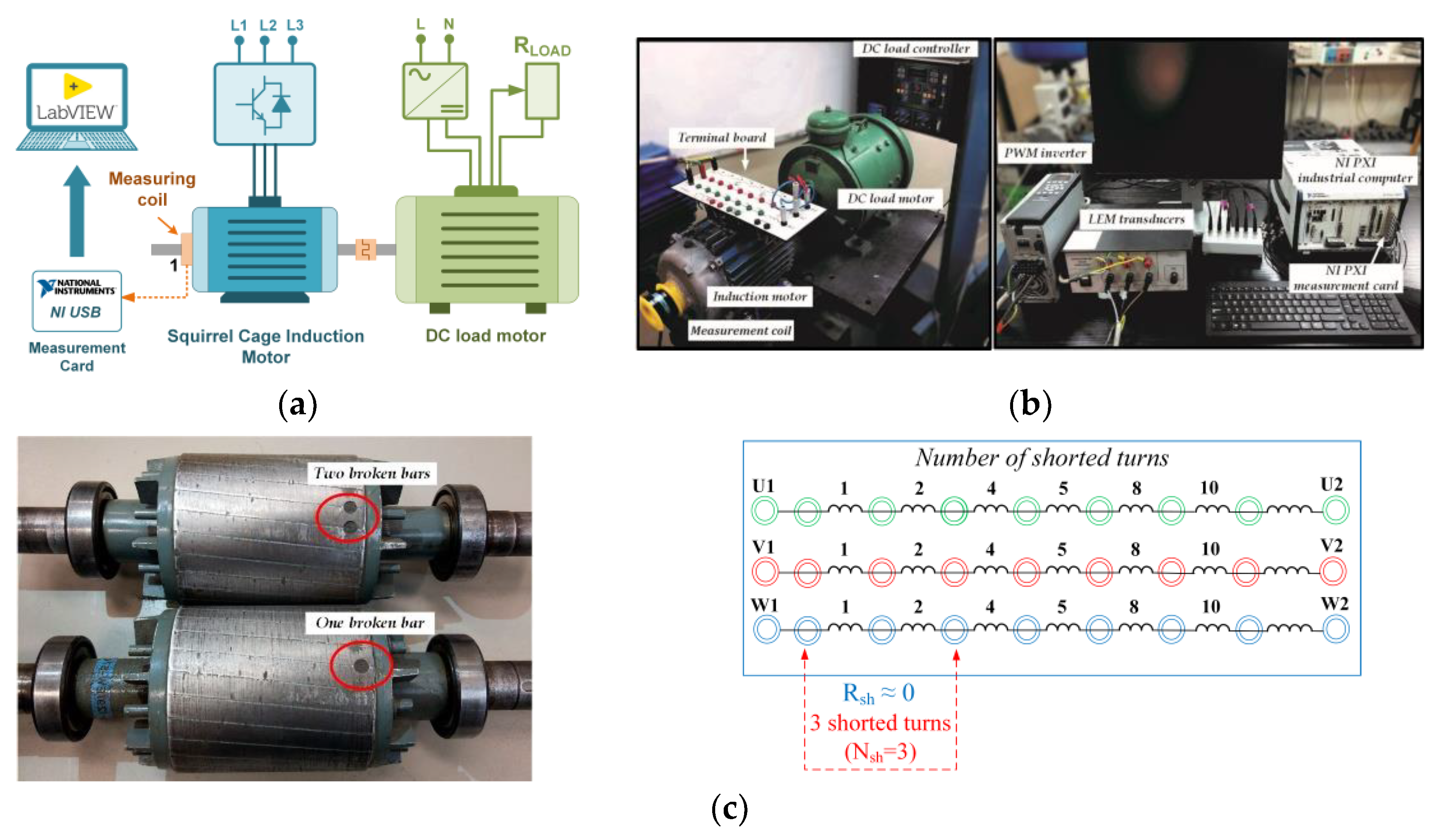
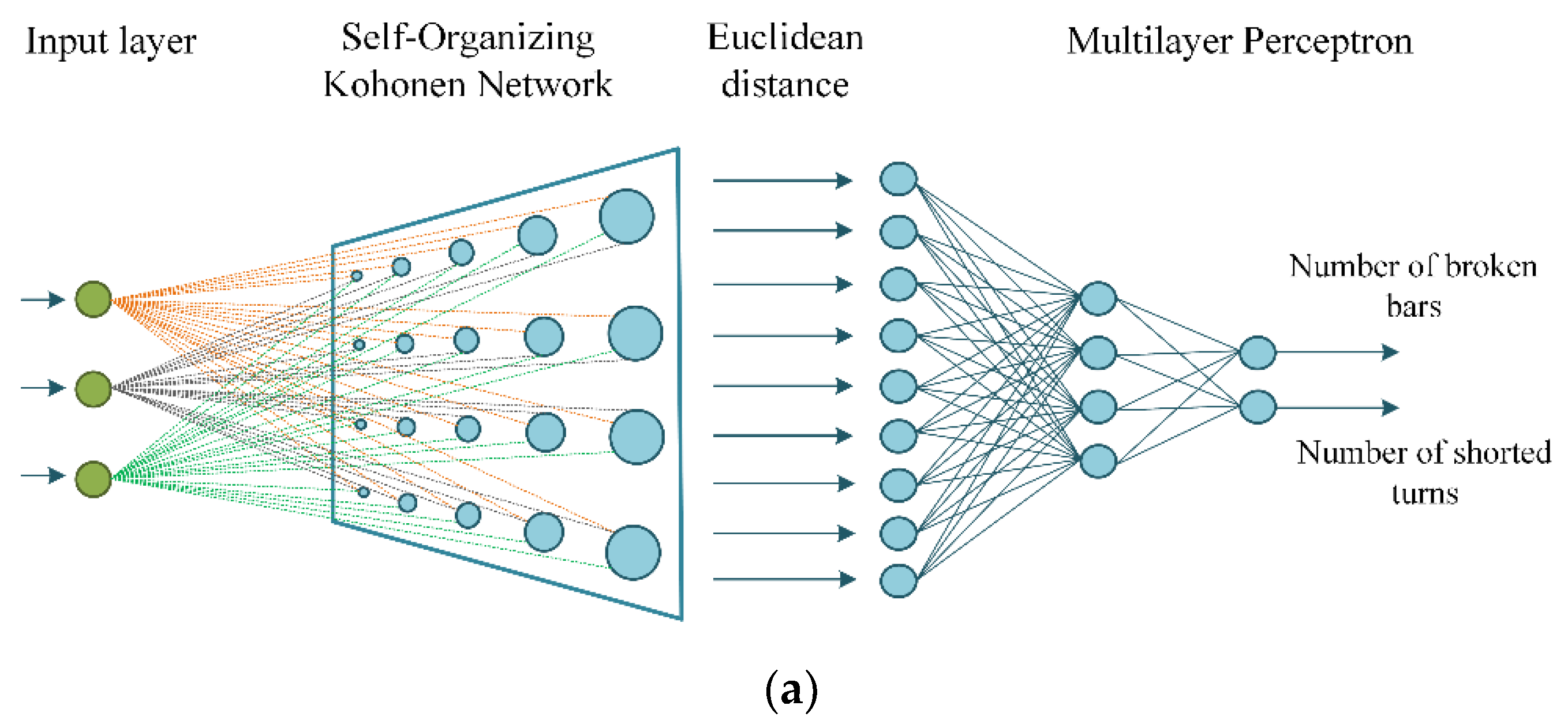
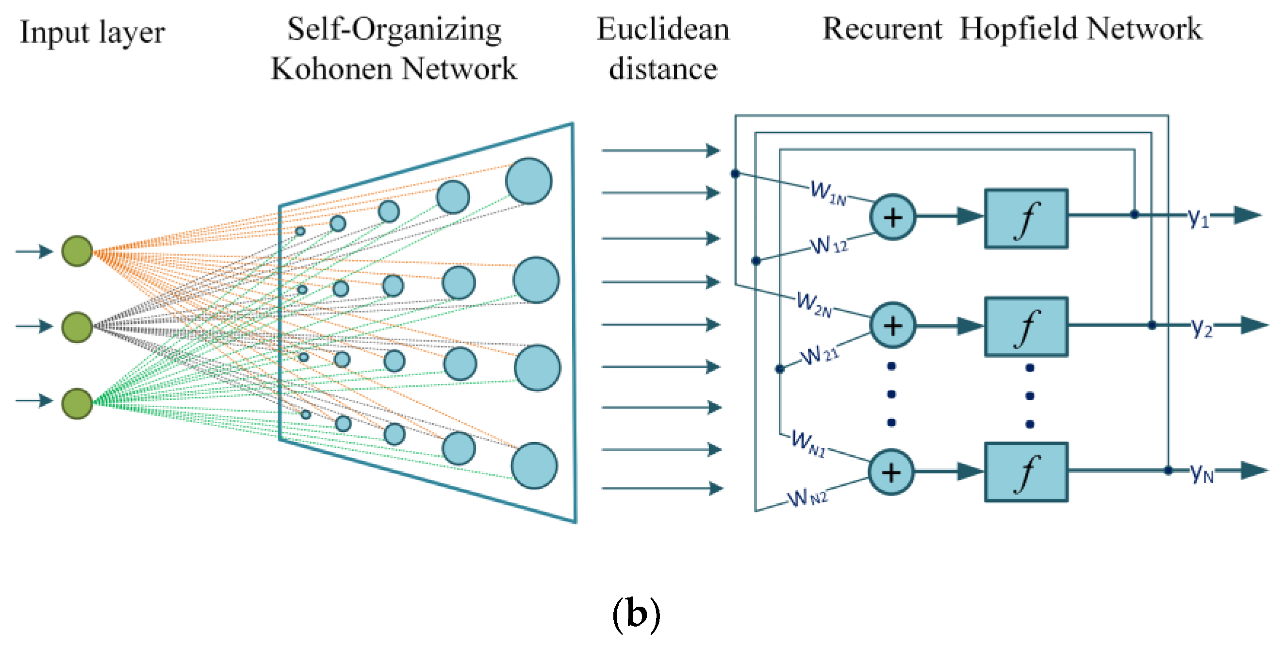
This article proposes the use of cascaded NN (CdNN) structures to assess their effectiveness in the classification and determination of the level of IM electrical winding damages in their initial stage. The specific CdNNs, which are composed of SOM and MLP networks, as well as SOM and RHN, are presented. The efficiency of such extended structures of fault detectors for IM stator and rotor windings in the detection of damage type and level is analyzed, both for single faults and mixed damages. The fault symptoms obtained from a fast Fourier transform (FFT) of the diagnostic signal (voltage induced in the axial flux measuring coil, similarly to [6,26]) are used as the CdNNs’ input.
The novelty of the solution presented in this article results from the structures used, as well as the method of signal transmission between individual CdNN members.
The article consists of six sections. After this introduction, the second section discusses the use of the axial flux signal as a source of diagnostic information. The third section is devoted to discussing selected classic neural structures in the detection of IM electrical circuit faults, especially in their initial phase. The subsequent two sections present the idea and results of the experimental verification of the developed cascaded neural structures (a specific type of the hybrid NNs). The article ends with a discussion of the benefits obtained from the use of CdNN structures.

2. Efficiency Comparison of the Classic Neural Detectors of IM Winding Damages Based on the Axial Flux Signal

2.1. Short Information on Diagnostic Signal Assessment Used for Winding Fault Detection of the Induction Motor

In this work, one of the most commonly used signals in diagnostic techniques, namely the axial flux, was used to train neural network (NN)-based detectors for IM winding damages. All electric machines are characterized by the existence of certain asymmetries of electric or magnetic circuits, mainly related to the inability to ensure ideal parameters in the production of machines and their use. The effect of these inaccuracies is the existence of the stray flux (Figure 1), whose value depends on the level of machine asymmetry. Due to the fact that the stray flux (axial or radial) finds its source in the currents flowing through the motor windings, damage to electrical circuits will also be reflected in this signal. Therefore, the interaction between the damage and the flux value allows the use of this physical quantity to assess the defect degree in electric motors.
In most applications, the technical condition assessment of the IM based on the axial flux signal is carried out using the fast Fourier transform (FFT) of the voltage induced in the measuring coils (Figure 1b). Despite the high efficiency of fault detection, FFT requires signal stationarity as well as a relatively long measurement time. The measurement time plays a key role in the case of stator winding short circuits characterized by extremely fast damage progression. This aspect will be discussed in more detail later in this article.
The analysis of the axial flux spectrum consists of observing the amplitudes of the spectral components with frequency characteristics for individual defects. The assessment of the damage degree will depend on the trend of changes in the amplitude values of individual harmonic components, which were described, among others, in [6,26]:
-
for stator winding short-circuits, these are harmonics with frequencies (fsh, where subindex sh stands for shorted-turns harmonics) that depend on the supply voltage frequency, fs, and the motor slip, s:
f s h = f s ( m ± k ( 1 s ) p p ) ,
for damage to the rotor cage, harmonic frequencies (fbb, where subindex bb stands for broken rotor bar harmonics) appear in the axial flux spectrum associated with the asymmetry of the currents (Equations (2) and (3)), as well as with changes in the local field rotating at the rotor speed (Equation (4)):
f b b 1 = m s f s ,
f b b 2 = f s ( 1 ± 2 k s ) ,
f b b 3 = k f r ± m s f s ,
where fr is the rotational frequency; pp is the number of pole pairs; and m = 1, 3, 5, …, 2pp–1, k = 1, 2, 3….
The presented spectra allow precisely observation of how the inter-turn short circuits (Figure 2a) and the cracks of the rotor cage bars (Figure 2b) influence the axial flux signal. The selection of the symptoms of rotor and stator defects is in most cases the result of an analysis of the trend of the amplitude values of the spectrum components in connection with the occurrence of damage. In order to specify the degree of damage to the IM stator and the rotor windings, the following notation was used in this work: Nsh is the number of shorted turns of stator winding, Nbb is the number of broken rotor cage bars, TL is the load torque, and TLN is the rated load torque.
The amplitudes of selected harmonics of the voltage induced by the axial flux in the measuring coil are the input signals of the designed neural fault detectors. In the presented studies, the signal spectra in decibels are marked as |ufp|dB, where fp is the specific frequency of the spectrum component. The advantages of using the axial flux signal in the diagnostic processes are the non-invasive measurement, low cost of the measuring system, as well as the high sensitivity of this signal to field asymmetries, which occur during the analyzed winding damages.
The axial flow spectra were obtained from measurements taken on a specially prepared IM test stand, where it was possible to physically model stator winding defects (inter-turn short circuits) or rotor cage damages (broken bars in replaceable rotors). A general view of the test stand and the physical modeling method of stator and rotor winding damages is shown in Figure 3.
The 1.5 kW motor was powered from the frequency converter and operated in an open scalar control loop in the frequency range of fs = 20–50 Hz, with load torques in the range of (0–1) TLN. The motor nominal data are shown in Table A1 in the Appendix A. The tested IM was loaded by means of a mechanically coupled DC machine. The axial flux measurement system (coil placed on the outer surface of the motor casing, coaxial with the shaft) enabled the diagnostic signal analysis for various machine operating conditions.
The test stand enabled physical modeling of the stator winding short circuits and rotor damage (replaceable squirrel cage rotors with different numbers of damaged bars). The tests were conducted for various stator and rotor faults, as well as for mixed faults:
0–6 shorted turns in one stator winding phase,
0–3 broken rotor bars.
Based on the conducted tests, samples used in the process of learning and testing the studied neural structures in the Matlab environment [33] were collected. NN detectors were then implemented in the National Instruments LabVIEW environment (Austin, Texas, USA) using the matrices of weighting factors obtained after the learning and testing process.

2.2. Characteristics of Classic NN Efficiency in IM Winding Fault Detection

This section, based on the work of [11,26] and additional analyses carried out for the purposes of this article, presents the basic advantages and disadvantages of three types of neural structures—SOM, MLP, and RHN–when applied in the detection and classification of damages to the electric windings of an IM fed from a frequency converter.
The symptoms of the stator and rotor faults in the form of magnitudes of the axial flux spectrum were selected as elements of input vectors of the analyzed NNs. As was mentioned previously, the selection of these symptoms is in most cases the result of an analysis of the trend of the amplitude values of the spectrum components in connection with the occurrence of damage. Therefore, it is an empirical approach that requires observation of the influence of the information used on the accuracy of the NN. Moreover, the amount of input information (size of the input vector) is directly related to the type of neural network constituting the decision part of the IM fault detector. In order to describe the effectiveness of neural structures, indices ηd and ηc were determined, which describe the effectiveness of damage detection and classification, respectively.
η d = X P X F + X U ,
η c = 1 N c i = 1 N c X P i X i ,
where XP is the number of positive (correct) neural network responses (faulty or unfaulty motor state), XF is the number of faulty states, XU is the number of unfaulty states, Nc is the number of considered fault categories (stator faults—Nc = 7; rotor faults—Nc = 4; mixed faults—Nc = 28), XPi is the number of positive (correct) responses for the considered fault categories, and Xi is the number of cases in each category.

2.2.1. Self-Organizing Kohonen Network SOM

The first of the classic NN structures analyzed was the self-organizing Kohonen network belonging to data classifiers. Table 1 presents a summary of the results of the experimental research on the use of SOM as the neural fault detector of IM electrical circuits. The input vector of the network contained the amplitudes of the harmonics of the axial flux spectrum at frequencies fs and 3sfs. In the network training process, data from 125 measurements of the diagnostic signal were used (25 measurements for undamaged motor, 25 measurements for stator inter-turn short circuits (from 1 to 6 turns), 25 measurements for each damaged rotor (with 1–3 broken bars)). The training vector did not contain samples for the mixed damage case. The “winner takes most” (WTM) training method was used in the learning procedure. The input vector used during the testing process of the SOM network was developed based on data from 110 samples, which was different from those used during the network training procedure, which also contained mixed fault types.
Very good damage type detection efficiency was obtained for SOM networks, while the responses were less precise regarding the damage level, especially for stator winding inter-turn short circuits. Similarly poor results were obtained in the case of the mixed damage analysis (Table 1).

2.2.2. Multilayer Perceptron (MLP)

The next analyzed neural structure was a feedforward multilayer perceptron (MLP), the most often used NN in diagnostic procedures. The implementation of an MLP network in the detection and classification of stator and rotor faults began with the analysis of the impact of the MLP structure on the efficiency of such a fault detector. The best results were obtained for NN with {3–12–8–2}, with 3 inputs and 12 and 8 neurons (with sigmoidal activation functions) in the hidden layers, respectively. The input vector contained the amplitudes of the three harmonics of the axial flux spectrum with frequencies fs, sfs, and 3sfs. In total, 300 samples obtained for different frequencies of the motor supply voltage and different load torque conditions were used for network training. The measurement data not used in the learning procedure of the MLP–based detector (280 samples) were used to test the network. When developing MLP fault detectors, particular attention was paid to the effectiveness of detecting both single and mixed motor winding faults. The results regarding the effectiveness of the developed MLP detector in the case of various types of winding damage are presented in Table 2.

2.2.3. Recursive Hopfield Network (RHN)

The other NN tested in the task of IM winding fault detection and classification was the recursive Hopfield network (RHN). The training procedure was conducted with the training vector obtained on the basis of 200 measurements. As the RHN network requires more inputs than MLP or SOM, nine amplitudes of the harmonics of the axial flux spectrum at the following frequencies were used as the training vector elements: fs, fs + 2fr, 3fs2fr, 5fs + 3fr, fs4sfs, sfs, 3fr + sfs, 5frsfs. The learning procedure for the Hopfield network consisted of determining the values of the weight and bias matrices. The verification of the weight selection correctness was carried out in accordance with the pseudo-inversion principle by providing the training vector to the input of the network. The results of the experimental verification are presented in Table 3.

2.3. Comparison of the Winding Fault Detectors Based on the Classic Neural Networks

Based on the detailed analysis carried out in [11,26] and the results presented above, the following conclusions can be formulated regarding the disadvantages and advantages of NN damage detectors of IM windings based on the neural networks (Table 4).
Due to the abovementioned disadvantages of the analyzed classic NN structures, an attempt was made to use their advantages and eliminate the disadvantages by connecting selected networks into hybrid (cascaded) structures, which will be described in the next section.

3. Cascaded Neural Structures and Their Efficiency

3.1. Development of CdNN Input Vectors

Based on the conclusions presented in the previous section, the CdNN structures were developed (i.e., networks constituting a cascade connection of SOM and MLP (SOM-MLP), as well as SOM and RHN (SOM-RHN)), which are presented in Figure 4. The selected amplitudes of the axial flux spectrum at characteristic frequencies, determined in accordance with Equations (1)–(4), which are the symptoms of damage to the stator and rotor windings of the IM, were used as the components of the input vector of the supervising SOM structure (10 × 10). The WTM method was chosen to train this network.
The idea of the developed structure of the proposed CdNN consists of the replacement of the usually used information about the number of winning neurons of the supervising SOM network by the distance matrix between the input vector and all SOM neurons:
d E ( x i , w i j ) = x i w i j = j = 1 N ( x i w i j ) 2 .
In Figure 5, a schematic diagram of an intermediate block of the developed CdNN structures is presented.
The processing of the SOM output information was carried out in 4 steps:
(1)
Replacement of the information about the winning neuron number with an Euclidean measure of the distance between the network input and all SOM neurons;
(2)
Recording of the Euclidean distance measure in the form of a matrix with dimensions equal to the size of the selected Kohonen map (in this case (10 × 10));
(3)
Conversion of the matrix (10 × 10) to the vector (1 × 100);
(4)
Vector normalization for subordinate networks (MLP inputs = [0,1], RHN inputs = [−1,1]).
The parameters of the SOM network and its training process are compiled in Table 5.

3.2. Results of Supervising SOM Training

During the learning process, the Gaussian neighborhood function and initial neighborhood range equal to the size of the Kohonen map were adopted. As a result, the network response to learning data was characterized by a smooth transition between map areas characteristic of individual motor failures. Figure 6 shows the learning process of the designed SOM network. The network learning time was very short; for 10,000 epochs, it was 300 s.
The SOM network responses to a test vector containing samples corresponding to both stator and rotor faults, as well as mixed damages, including very low load torque conditions, are shown in Figure 7. Particularly in the latter case, the detection of the rotor damage is usually very difficult [9,10,11,12].

4. Efficiency Analysis of the Cascaded Network SOM–MLP

4.1. Structure and Training Results of Subordinate MLP Network

The SOM network output signals were used to train the MLP network, which was to be the second and subordinate part of this specific hybrid network. The parameters of the developed MLP network are shown in Table 6.
During the training, the Levenberg–Marquardt method was used with an initial learning factor of 0.5. The influence of the number of neurons in the hidden layer on the detection effectiveness of the degree of stator and rotor winding damage by the MLP network is analyzed and presented in Figure 8. As a result of these studies, 21 neurons in the hidden layer of MLP were adopted for the final implementation of this CdNN.

4.2. Experimental Verification of the Cascade Network SOM–MLP

The IM winding fault detection system using the SOM–MLP neural structure was designed to classify the damages and assess their degree. The developed CdNN was implemented on the test stand described in Section 2 using software made in the LabVIEW environment. The experimental verification included the following types of tests:
efficiency assessment of the SOM–MLP network in the determination of the degree of stator winding damage,
efficiency assessment of the SOM–MLP network in the determination of the degree of damage to the rotor winding,
efficiency assessment of the SOM–MLP network in the determination of the degree of mixed damage,
efficiency assessment of the SOM–MLP network in the determination of the degree of damage to the rotor winding at no load.
Figure 9 and Figure 10 show the CdNN responses to a given input vector, whose elements were the amplitudes of the harmonics of the axial flux spectrum at frequencies: fs, fs+fr, 3fs −3fr, 3sfs. The developed CdNN has very high efficiency values for detecting and classifying stator defects of 98.6% and 88.7%, respectively, as shown in Figure 9a. A few NN errors in this task may occur due to similar quantitative changes in the diagnostic signal in the case of short circuits with 4–6 turns of the stator. In the case of the rotor fault detection (Figure 9b), the developed system provided false information about the condition of the rotor bars only once. Considering the fact that the main task of the diagnostic system is to detect damage at the earliest possible stage, the effectiveness of CdNN is close to 99.6%.
Figure 10 shows the most important features of the developed CdNN network, namely the ability to classify mixed faults in the case of different IM operating conditions (Figure 10a) and the high precision of rotor damage detection in the absence of the load torque, i.e., for the motor slip close to zero (Figure 10b).
The results presented in Figure 10a show that the developed CdNN structure allows the correct recognition of the technical condition of the stator and rotor windings, even during simultaneous damage. The difficulty in carrying out this type of task is related to relationships between the damage symptoms, which are hard to determine and yet are characteristic of the discussed winding faults during IM operation in the whole range of changes of the load torque and the frequency of the supply voltage. This fact results directly from the relationships describing the axial flux spectrum frequencies characteristic of rotor and stator winding damages (Equations (1)–(4)).
Particularly noteworthy are the results shown in Figure 10b, due to the fact that when the motor is idling, the components of the axial flux spectrum characteristic of the incipient rotor fault coincide with those for the motor without damage in the rotor (Equation (3)). However, in the case of the developed CdNN, an efficiency result for rotor failure detection of the load torque TL≈0 of close to 90% was obtained, which is a very good result compared to the effectiveness of a single SOM network or MLP network, as shown in Section 2.2.1 and Section 2.2.2 and in [25].
By analyzing the accuracy of the hybrid structure’s response to the damaged/undamaged question, the developed CdNN provided correct information in more than 98% of cases.

5. Efficiency Analysis of the Cascaded Network SOM–RHN

5.1. Structure and Training Results of Subordinate RHN

The second of the developed CdNNs was a combination of a self-organizing Kohonen network and a recursive Hopfield network. In order to compare the developed CdNN structures, the experimental verification of the SOM–RHN network was carried out in a manner analogous to SOM–MLP, which included the following types of tests:
efficiency assessment of the SOM–RHN network in the determination of the degree of stator winding damage,
efficiency assessment of the SOM–RHN network in the determination of the degree of damage to the rotor winding,
efficiency assessment of the SOM–RHN network in the determination of the degree of mixed damage,
accuracy assessment of the SOM–RHN network in the determination of the degree of damage to the rotor winding at no load.
The parameters of the developed RHN network are shown in Table 7.

5.2. Experimental Verification of the SOM–RHN Cascade Network

The results of the experimental verification of the developed SOM–RHN structure are shown in Figure 11 and Figure 12. By analyzing the received CdNN responses to the given test vectors, it was noted that the SOM–RHN structure was characterized by lower detection (97.2%) and classification (80.3%) of the stator winding damage (Figure 11a) compared to the structure of SOM–MLP. In addition, incorrect network responses appear more randomly, making it more difficult to determine their sources. Nevertheless, the extension of RHN to the precedent SOM network enables a significant improvement in fault detection and classification ability in comparison to a single RHN structure (Table 3).
The developed SOM–RHN structure is also characterized by the high efficiency of detection (100%) and classification (91.5%) of defects in the rotor cage bars. CdNN provided incorrect diagnostic information only in the event of damage to 3 rotor cage bars. This fact is not a diagnostic limitation due to the high efficiency of the SOM–RHN structure in the initial stages of rotor damage, which can be seen in Figure 11b.
The last stage of the experimental verification of the developed structure included the detection and classification of mixed failures (Figure 12a) and rotor defects during no load operation of the tested machine (Figure 12b). This stage of research was a key indicator of the quality of the cascade structure developed. This fact is related to the total lack of ability of individual SOM and RHN networks to recognize mixed damages. In connection with the above, the improvement of the effectiveness of detection and classification of mixed damages determines the validity of using hybrid solutions in electrical winding fault detection and classification of IM.
During the analysis of the results presented in Figure 12a, it was observed that the efficiency of the mixed damage classification was about 75%, which compared to the inability to assess this type of damage by a single RHN (Table 3) is a significant improvement. It should be noted here that when modeling mixed damages, 4–6 shorted turns were used. Possible errors of the NN could, therefore, result from quantitatively similar changes in the diagnostic signal in the case of these damages.
Figure 12b shows the response of the developed cascade neural structure in the case of damage to the rotor cage bars when the motor is running without load torque. Difficulties in recognizing this type of damage result from the analysis of the diagnostic signal, as mentioned in Section 4.2. Nevertheless, the SOM–RHN network provided the correct answer in more than 81.6% of cases.

6. Results

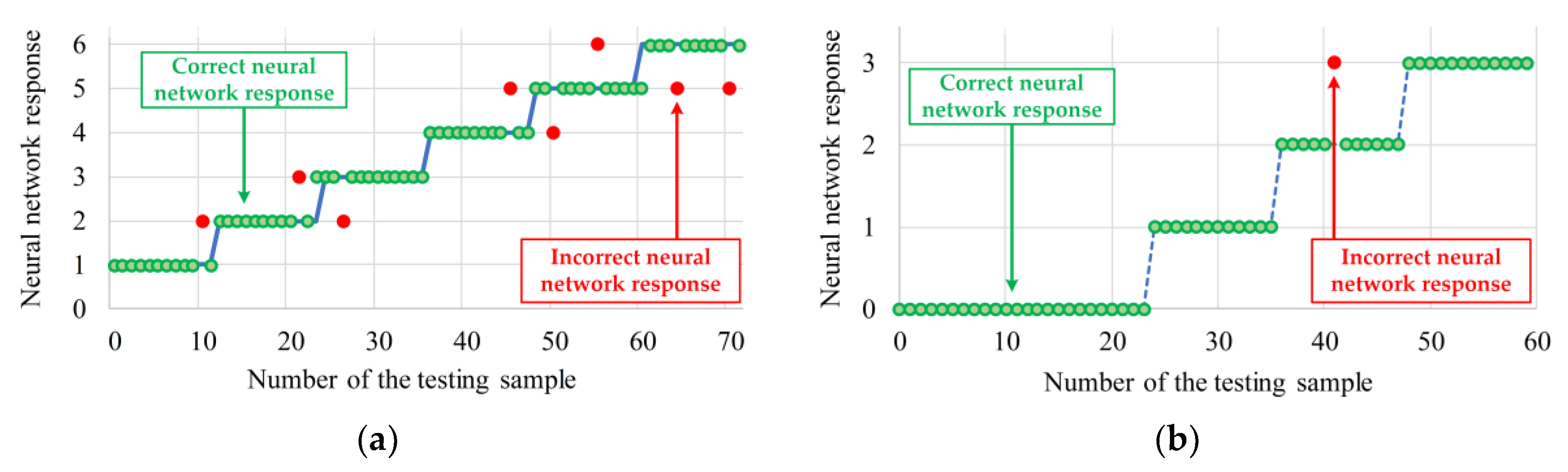
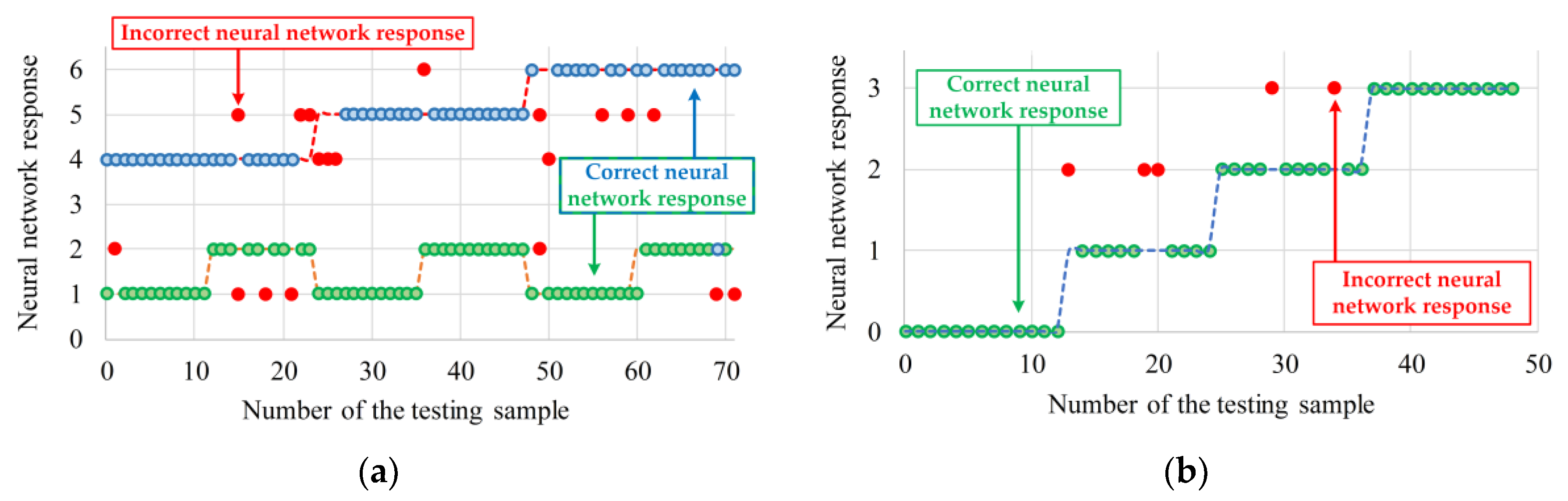
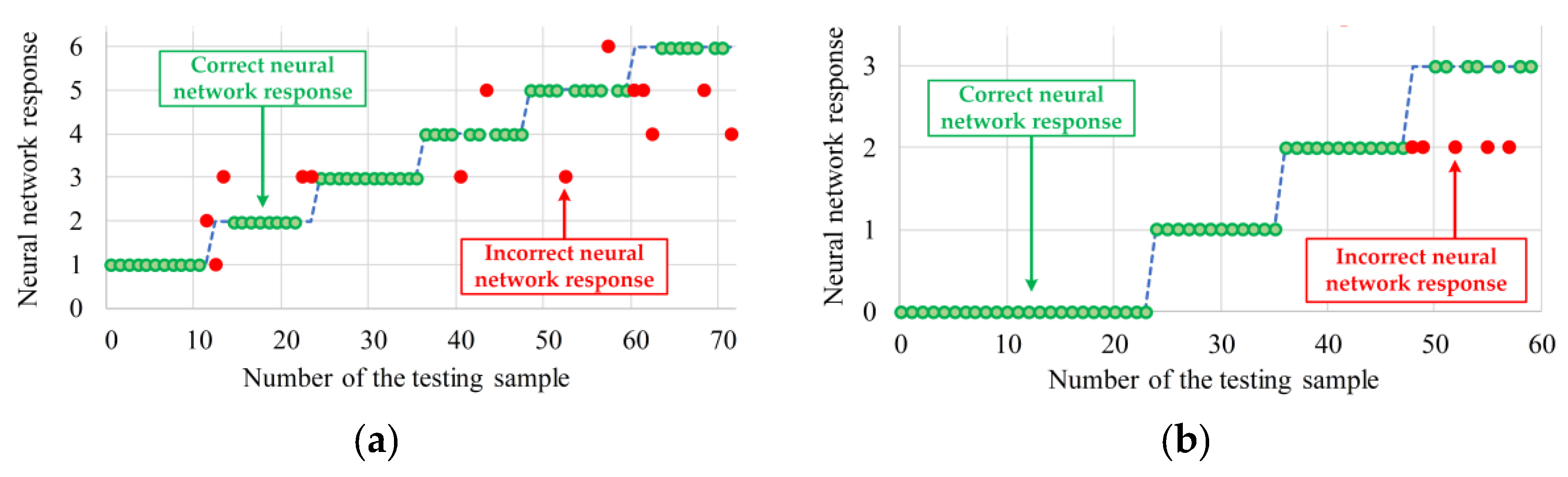
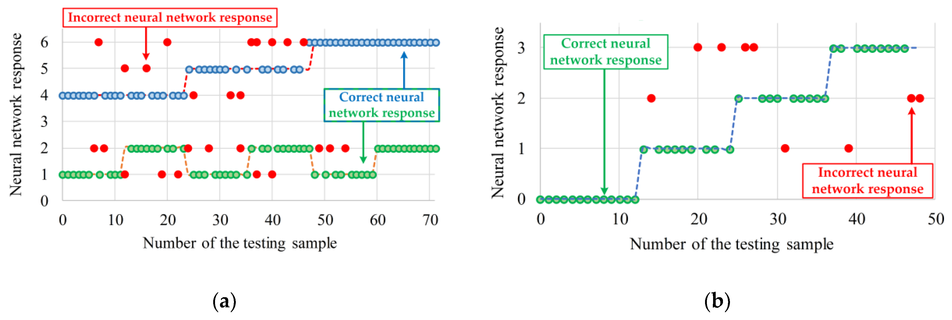
The use of cascaded structures of neural networks in the form of a classifier (SOM) and data analyzer (MLP or RHN) for the classification and detection of IM winding fault levels, in particular in their initial phase (incipient fault analysis), enabled the elimination of the basic disadvantages of individual single NNs used for such tasks.
Kohonen’s self-organizing SOM network eliminated the following disadvantages:
no gradation of stator damage,
difficulty in assessing the degree of damages (area boundaries),
difficulty of automating the detection process,
impossibility to assess mixed damages.
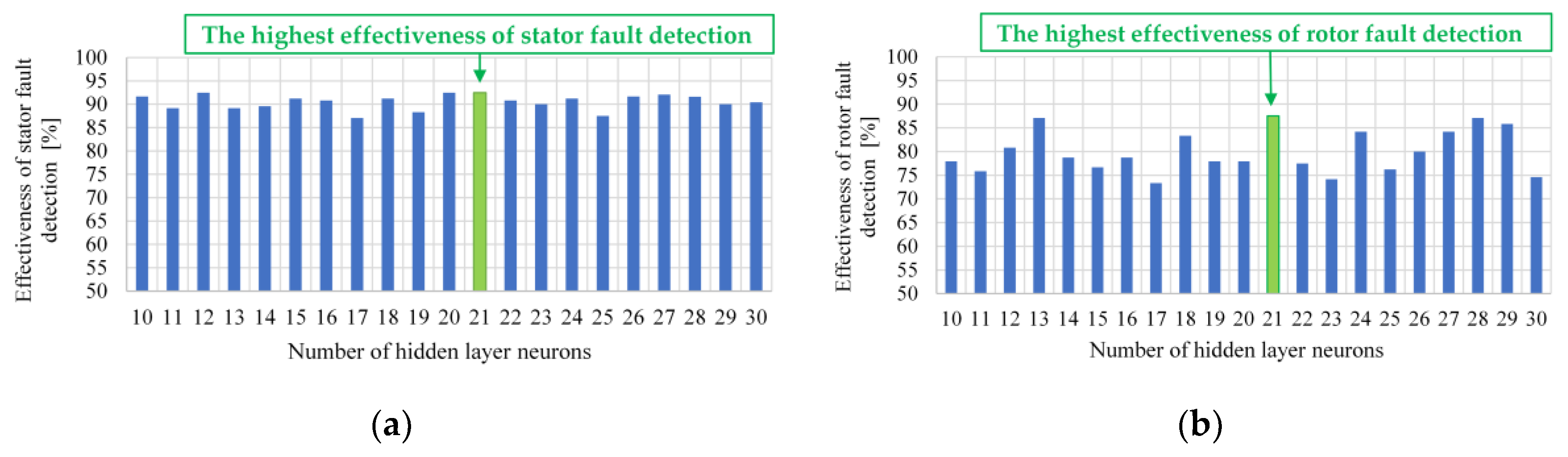
In the case of MLP networks, it eliminated:
long learning process,
impossibility of the detection of rotor bar damages at TL < 0.1 TLN,
need for 2 hidden layers due to mixed damage.
By contrast, for the recursive Hopfield network the following disadvantages were eliminated:
lack of robustness to measuring disturbances,
strong dependence of the detection efficiency on the base vector,
lack of resistance to object changes,
inability to assess mixed damages,
strong dependence of the detection efficiency on the number of network inputs.
It can be summarized that the main improvements to the effectiveness of detection and classification of mixed damages (including initial fault levels), as well as the possibility of the detection of rotor bar damages at TL < 0.1TLN, determine the validity of using hybrid solutions in electrical winding fault detection and classification of IM, especially for the SOM–MLP combination structures.
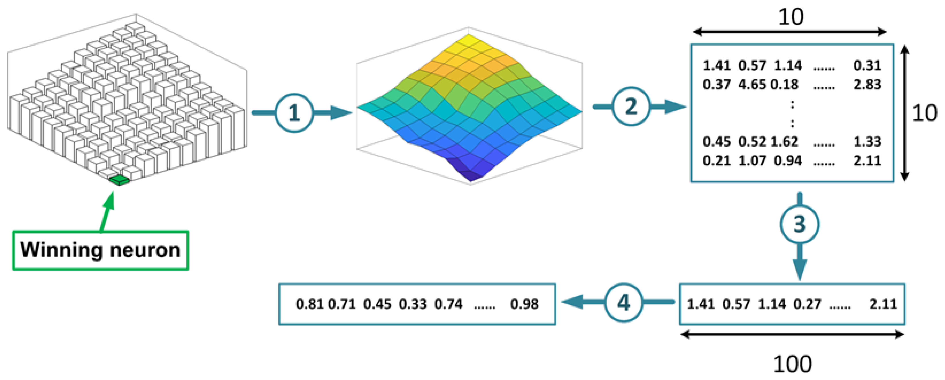
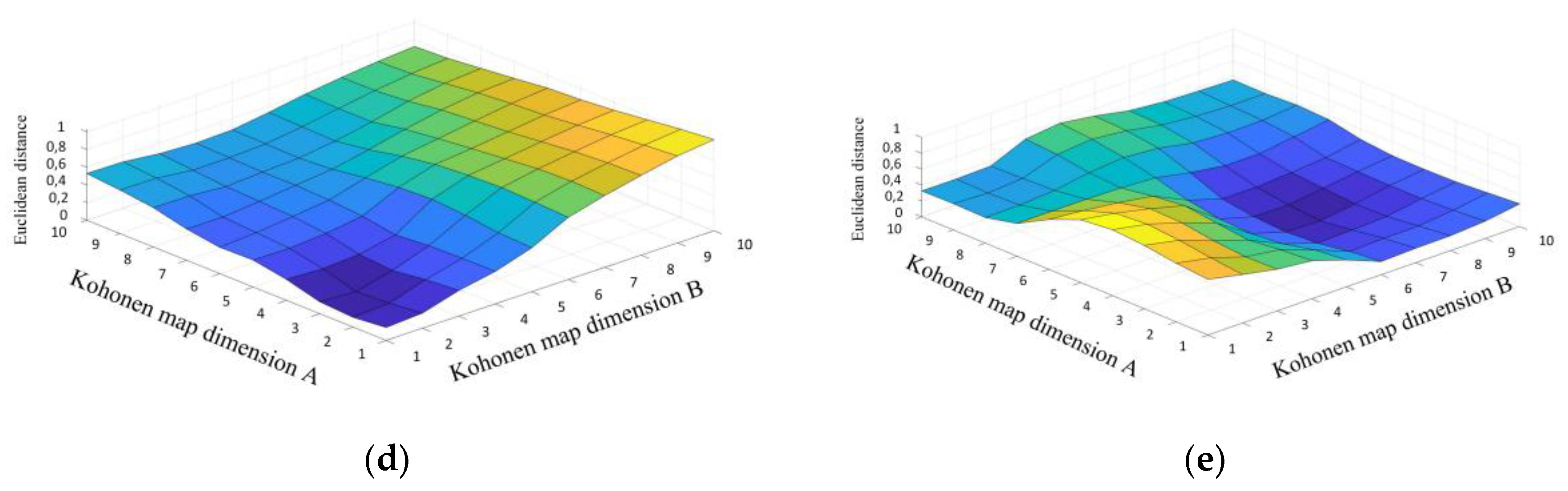
During the experimental verification of the implemented cascade neural networks, it was observed that the effectiveness of the final assessment of the technical condition of the machine depends mainly on the self-organizing Kohonen network. In the presented application, the SOM performs the function of a diagnostic information generator, indirectly providing information on the current state of the tested machine (type of damage, degree of damage). In connection with the above, the SOM, which is the superior element of the CdNN, gives the NN the ability to recognize damage, as well as assesses the network resistance to the interference occurring during the measurement, processing, and transmission of diagnostic information. The task of the second and subordinate CdNN module is to correctly read the information stored in the form of a vector of the Euclidean measures of distance between the input vector and SOM neurons. Therefore, when designing cascade-based neural damage detectors, special attention should be paid to the correct selection of the structure and parameters of the training process of the self-organizing Kohonen network.
The main features of the proposed CdNNs are summarized in the following Table 8.

Author Contributions

All of the authors contributed equally to the conception of the paper. M.S. and T.O.-K. proposed the methodology and paper organization. M.S. carried out the measurements and analyzed the experimental data. T.O.-K. prepared the original draft and supervised the project. M.S. validated the obtained results. T.O.-K. revised and edited the final paper. All authors have read and agreed to the published version of the manuscript.

Funding

This research was partly supported by the National Science Centre Poland under grant number 2017/27/B/ST7/00816 and by statutory funds of the Department of Electrical Machines, Drives and Measurements of the Wroclaw University of Science and Technology (2020).

Conflicts of Interest

The authors declare no conflict of interest.

Appendix A

Table A1. Rated parameters of the tested induction motor.
Name of the ParameterSymbolUnits
PowerPN1500[W]
TorqueTN10.16[Nm]
SpeednN1410[r/min]
Stator phase voltageUsN230[V]
Stator currentIsN3.5[A]
FrequencyfsN50[Hz]
Pole pairs numberpp2[-]
Number of rotor bars Nrb26[-]
Number of stator turns in each phaseNst312[-]

References

  1. Tavner, P.; Ran, L.; Penman, J.; Sedding, H. Condition monitoring of rotating electrical machines. Iet Power Energy Ser. 2008, 59. [Google Scholar] [CrossRef]
  2. Electric Power Research Institute EPRI Reports: Motor and Generator Insulation Life Estimation; Electric Power Research Institute: Palo Alto, CA, USA, 1992; Volume 1000185.
  3. Hamdani, S.; Touhami, O.; Ibtiouen, R.; Fadel, M. Neural network technique for induction motor rotor faults classification-dynamic eccentricity and broken bar faults. In Proceedings of the 8th IEEE Symposium on Diagnostics for Electrical Machines, Power Electronics & Drives (SDEMPED), Bologna, Italy, 5–8 September 2011; pp. 626–631. [Google Scholar] [CrossRef]
  4. He, Q.; Du, D. Fault diagnosis of induction motor using neural networks. In Proceedings of the 2007 International Conference on Machine Learning and Cybernetics, Hong Kong, China, 19–22 August 2007; pp. 1090–1095. [Google Scholar] [CrossRef]
  5. Taïbi, Z.M.; Hasni, M.; Hamdani, S.; Rahmani, O.; Touhami, O.; Ibtiouen, R. Optimization of the feedforward neural network for rotor cage fault diagnosis in three-phase induction motors. In Proceedings of the 2011 IEEE Int. Electric Machines & Drives Conference (IEMDC), Niagara Falls, ON, Canada, 15–18 May 2011; pp. 194–199. [Google Scholar] [CrossRef]
  6. Ewert, P. Application of neural networks and axial flux for the stator and rotor fault detection of induction motor. Power Electron. Drives 2019, 4, 203–215. [Google Scholar] [CrossRef] [Green Version]
  7. Boukra, T.; Lebaroud, A.; Clerc, G. Statistical and neural-network approaches for the classification of induction machine faults using the ambiguity plane representation. IEEE Trans. Ind. Electron. 2013, 60, 4034–4042. [Google Scholar] [CrossRef]
  8. Ghate, V.N.; Dudul, S.V. Optimal MLP neural network classifier for fault detection of three phase induction motor. Expert Syst. Appl. 2010, 37, 3468–3481. [Google Scholar] [CrossRef]
  9. Gardel, P.; Morinigo-Sotelo, D.; Duque-Perez, O.; Perez-Alonso, M.; Garcia-Escudero, L.A. Neural network broken bar detection using time domain and current spectrum data. In Proceedings of the 2012 20th International Conference on Electrical Machines, Marseille, France, 2–5 September 2012; pp. 2492–2497. [Google Scholar] [CrossRef]
  10. Toma, S.; Capocchi, L.; Capolino, G. Wound-rotor induction generator inter-turn short-circuits diagnosis using a new digital neural network. IEEE Trans. Ind. Electron. 2013, 60, 4043–4052. [Google Scholar] [CrossRef] [Green Version]
  11. Skowron, M.; Wolkiewicz, M.; Orlowska-Kowalska, T.; Kowalski, C.T. Application of self-organizing neural networks to electrical fault classification in induction motors. Appl. Sci. 2019, 9, 616. [Google Scholar] [CrossRef] [Green Version]
  12. Kowalski, C.T.; Orlowska-Kowalska, T. Neural networks application for induction motor faults diagnosis. Math. Comput. Simul. 2003, 63, 435–448. [Google Scholar] [CrossRef]
  13. Khalfaoui, N.; Salhi, M.S.; Amiri, H. The SOM tool in mechanical fault detection over an electric asynchronous drive. In Proceedings of the 2016 4th International Conference on Control Engineering & Information Technology (CEIT), Hammamet, Tunisia, 16–18 December 2016; pp. 1–6. [Google Scholar] [CrossRef]
  14. Sid, O.; Menaa, M.; Hamdani, S.; Touhami, O.; Ibtiouen, R. Self-organizing map approach for classification of electrical rotor faults in induction motors. In Proceedings of the 2011 2nd International Conference on Electric Power and Energy Conversion Systems (EPECS), Sharjah, UAE, 15–17 November 2011; pp. 1–6. [Google Scholar] [CrossRef]
  15. Kato, T.; Inoue, K.; Takahashi, T.; Kono, Y. Automatic fault diagnosis method of electrical machinery and apparatus by using Kohonen’s self-organizing map. In Proceedings of the 2007 Power Conversion Conference, Nagoya, Japan, 2–5 April 2007; pp. 1224–1229. [Google Scholar] [CrossRef] [Green Version]
  16. Coelho, D.N.; Barreto, G.A.; Medeiros, C.M.S. Detection of short circuit faults in 3-phase converter-fed induction motors using kernel SOMs. In Proceedings of the 2017 12th International Workshop on Self-Organizing Maps and Learning Vector Quantization, Clustering and Data Visualization (WSOM), Nancy, France, 28–30 June 2017; pp. 1–7. [Google Scholar] [CrossRef]
  17. Gui-li, Y.; Shi-wei, Q.; Mi, G. Motor fault diagnosis of RBF neural network based on immune genetic algorithm. In Proceedings of the 2013 25th Chinese Control and Decision Conference (CCDC), Guiyang, China, 25–27 May 2013; pp. 1060–1065. [Google Scholar] [CrossRef]
  18. Dash, R.N.; Subudhi, B.; Das, S. A comparison between MLP NN and RBF NN techniques for the detection of stator inter-turn fault of an induction motor. In Proceedings of the 2010 International Conference on Industrial Electronics, Control and Robotics, Rourkela, India, 27–29 December 2010; pp. 251–256. [Google Scholar] [CrossRef]
  19. Kilic, E.; Ozgonenel, O.; Ozdemir, A.E. Fault identification in induction motors with RBF neural network based on dynamical PCA. In Proceedings of the 2007 IEEE International Electric Machines & Drives Conference, Antalya, Turkey, 3–5 May 2007; pp. 830–835. [Google Scholar] [CrossRef]
  20. Kowalski, C.T.; Kaminski, M. Rotor fault detector of the converter-fed induction motor based on RBF neural network. Bull. Pol. Acad. Sci. Tech. Sci. 2014, 62, 69–76. [Google Scholar] [CrossRef] [Green Version]
  21. Gao, X.Z.; Ovaska, S.J.; Dote, Y. Motor fault detection using Elman neural network with genetic algorithm-aided training. In Proceedings of the 2000 IEEE International Conference on Systems, Man and Cybernetics, Nashville, TN, USA, 8–11 October 2000; Volume 4, pp. 2386–2392. [Google Scholar] [CrossRef]
  22. Mahamad, A.K.; Hiyama, T. Improving Elman Network using genetic algorithm for bearing failure diagnosis of induction motor. In Proceedings of the 2009 IEEE International Symposium on Diagnostics for Electric Machines, Power Electronics and Drives (SDEMPED), Valencia, Spain, 27–30 August 2009; pp. 1–6. [Google Scholar] [CrossRef]
  23. Li, P.; Chai, Y.; Cen, M.; Qiu, Y.; Zhang, K. Multiple fault diagnosis of analogue circuit using quantum Hopfield neural network. In Proceedings of the 2013 25th Chinese Control and Decision Conference (CCDC), Guiyang, China, 25–27 May 2013; pp. 4238–4243. [Google Scholar] [CrossRef]
  24. Srinivasan, A.; Batur, C. Hopfield/ART-1 neural network-based fault detection and isolation. IEEE Trans. Neural Netw. 1994, 5, 890–899. [Google Scholar] [CrossRef] [PubMed]
  25. Hong, R.; Meizhu, L.; Mingfu, F. Equipment diagnosis method based on hopfield-bp neural networks. In Proceedings of the 2008 International Conference on Advanced Computer Theory and Engineering, Phuket, Thailand, 20–22 December 2008; pp. 170–173. [Google Scholar] [CrossRef]
  26. Skowron, M.; Wolkiewicz, M.; Orlowska-Kowalska, T.; Kowalski, C.T. Effectiveness of selected neural network structures based on axial flux analysis in stator and rotor winding incipient fault detection of inverter-fed induction motors. Energies 2019, 12, 2392. [Google Scholar] [CrossRef] [Green Version]
  27. Gutierrez, P.A.; Hervas-Martinez, C. Hybrid artificial neural networks: Models, algorithms and data. In Proceedings of the IWANN 2011, Part II, LNCS 6692; Cabestany, J., Rojas, I., Joya, G., Eds.; Springer-Verlag: Berlin/Heidelberg, Germany, 2011; pp. 177–184. [Google Scholar] [CrossRef]
  28. Goode, P.V.; Chow, M.Y. A hybrid fuzzy/neural system used to extract heuristic knowledge from a fault detection problem. In Proceedings of the 1994 IEEE, 3rd International Fuzzy Systems Conference, Orlando, FL, USA, 26–29 June 1994; Volume 3, pp. 1731–1736. [Google Scholar] [CrossRef]
  29. Nadjarpoorsiyahkaly, M.; Lim, C.P. A hybrid neural classifier for dimensionality reduction and data visualization and its application to fault detection and classification of induction motors. In Proceedings of the 2011 6th Int. Conf. Bio-Inspired Computing: Theories and Applications, Xi’an, China, 28–30 October 2011; pp. 146–150. [Google Scholar] [CrossRef]
  30. Santos, S.P.; Costa, J.A.F. A comparison between hybrid and non-hybrid classifiers in diagnosis of induction motor faults. In Proceedings of the 2008 11th IEEE Int. Conf. on Computational Science and Engineering, Washington, DC, USA, 16–18 July 2008; pp. 301–306. [Google Scholar] [CrossRef]
  31. Ince, T.; Kiranyaz, S.; Eren, L.; Askar, M.; Gabbouj, M. Real-time motor fault detection by 1-D convolutional neural networks. IEEE Trans. Ind. Electron. 2016, 63, 7067–7075. [Google Scholar] [CrossRef]
  32. Wu, S.; Chow, T.W.S. Induction machine fault detection using SOM-Based RBF neural networks. IEEE Trans. Ind. Electron. 2004, 51, 183–194. [Google Scholar] [CrossRef]
  33. Demuth, H.; Beale, M. Neural Network Toolbox-User’s Guide Ver.4. 1992–2004. Available online: http://128.174.199.77/matlab_pdf/nnet.pdf (accessed on 1 October 2004).
Figure 1. External stray (axial) flux in a squirrel cage induction motor (a) and method of possible placement used for the axial flux measuring coils (b).
Electronics 09 01314 g001
Figure 2. The effect of IM electrical circuit defects on the spectrum of the voltage induced in a measuring coil by an axial flux. Axial flux spectrum: (a) for an undamaged motor (Nsh = 0) and with 5 shorted turns in phase A (Nsh = 5), fs = 50Hz, TL=0.2 TLN; (b) for an undamaged motor (Nbb = 0) and with 3 broken rotor cage bars (Nbb = 3), fs = 50Hz, TL=0.8 TLN.
Electronics 09 01314 g002
Figure 3. Experimental setup: (a) general scheme of the setup; (b) components of the real experimental drive system; (c) illustration of the physical modeling of the stator and rotor faults, including connection of the stator winding for inter-turn short-circuit modeling and broken bar modeling in a squirrel cage rotor.
Electronics 09 01314 g003
Figure 4. Structures of the proposed cascaded neural networks: (a) SOM–MLP, (b) SOM–RHN.
Electronics 09 01314 g004aElectronics 09 01314 g004b
Figure 5. Transformation of the SOM outputs into input vectors for the subordinate network in the cascaded neural network (CdNN) structure.
Electronics 09 01314 g005
Figure 6. Training parameters of the SOM network: (a) neighborhood level; (b) learning rate; (c) learning time.
Electronics 09 01314 g006
Figure 7. The SOM responses to training data vector: (a) no fault; (b) broken rotor bars; (c) stator winding faults; (d) broker rotor bars = TL ≈ 0; (e) mixed damages.
Electronics 09 01314 g007aElectronics 09 01314 g007b
Figure 8. Effectiveness of motor fault detection by the MLP network: (a) broken rotor bars; (b) stator winding faults.
Electronics 09 01314 g008
Figure 9. SOM–MLP network response: (a) shorted turns of stator windings; (b) rotor broken bars.
Electronics 09 01314 g009
Figure 10. SOM–MLP network response: (a) mixed faults (blue dots—stator winding fault; green dots—rotor bar fault); (b) rotor broken bars, TL≈0 (s≈0).
Electronics 09 01314 g010
Figure 11. SOM–RHN network response: (a) shorted turns of stator windings; (b) rotor broken bars.
Electronics 09 01314 g011
Figure 12. SOM–RHN network response: (a) mixed faults (blue dots—stator winding fault; green dots—rotor bar fault); (b) rotor broken bars, TL ≈ 0 (s ≈ 0).
Electronics 09 01314 g012
Table 1. Effectiveness of the IM winding fault detection and classification using SOM.
Type of DamageDetection EffectivenessClassification Effectiveness
Stator winding faults≈93%≈70%
Rotor winding faults≈95%≈93%
Mixed faults≈70%-
No fault≈96%-
Table 2. Effectiveness of the IM winding fault detection and classification using MLP.
Type of DamageDetection EffectivenessClassification Effectiveness
Stator winding faults≈100%≈99.5%
Rotor winding faults≈100%≈87.3%
Mixed faults≈93%≈85.3%
No fault≈98.9%-
Table 3. Effectiveness of the IM winding fault detection and classification using RHN.
Type of DamageDetection EffectivenessClassification Effectiveness
Stator winding faults≈70%≈61%
Rotor winding faults≈90%≈87%
Mixed faults--
No fault≈80%-
Table 4. Comparison of the winding fault detectors based on classic NN.
AdvantagesDisadvantages
SOM
  • small amount of learning data ensuring high efficiency of classification
  • possibility to isolate map areas for rotor damages at load torques TL < 0.1TLN
  • simple hardware implementation (easy mathematical notation)
  • no gradation of stator damage
  • difficulty in assessing the degree of damage (overlapping boundaries of areas covering individual damages)
  • inability to assess mixed damages
  • difficulties in automating the detection process
MLP
  • high efficiency of damage grading
  • small size of the input vector
  • simple hardware implementation (simple mathematical description)
  • long learning process
  • impossibility of rotor damage detection at TL < 0.1TLN
  • need for application of 2 hidden layers due to mixed faults
RHN
  • ability to remember multiple samples (building objects)
  • very fast network learning process
  • simple hardware implementation (simple mathematical description)
  • no resistance to measuring disturbances
  • sensitivity to object changes
  • strong dependence of the detection efficiency on the base vector
  • inability to assess mixed damages
  • detection efficiency strongly depends on the number of network inputs
  • disturbances of one variable cause diagnostic information falsification
Table 5. Parameters of the SOM network and its training process.
Name of ParameterValue of Parameter
Training Vector Size240
Test Vector Size240
Number of Fault Categories20
Neural Network Inputs|ufs|dB, |ufs+fr|dB, |u3fs-3fr|dB, |u3sfs|dB
Training MethodsWTM (Winner Takes Most)
Neural Network Structure10 × 10
Number of Training Epochs10,000
Neural Network TopologyHexagonal
Neighborhood FunctionGaussian
Initial Neighborhood Radius10
Initial Learning Rate0.7
Table 6. Parameters of the MLP network and training process.
Name of ParameterValue of Parameter
Training Vector Size240
Test Vector Size240
Number of Fault Categories20
Neural Network InputsEuclidean distance
Training MethodsLevenberg-Marquardt
Activation FunctionHyperbolic Tangent
Number of Training Epochs350
Number of Hidden Layers1 (21 neurons)
Input Vector Size100
Output Vector Size2
Initial Learning Rate0.5
Table 7. Parameters of the RHN network and training process.
Name of ParameterValue of Parameter
Training Vector Size240
Test Vector Size240
Number of Fault Categories20
Neural Network InputsEuclidean distance
Training methodΔ projection method
Activation FunctionLinear
Input Vector Size100
Output Vector Size100
Initial Learning Rate0.7
Table 8. Evaluation of the developed CdNN-based IM winding fault detectors.
Evaluation CategoriesSOM + MLPSOM + RHN
Effectiveness of early detection of electrical damagesHIGHHIGH
Effectiveness of the stator damages level assessmentHIGHMEDIUM
Effectiveness of the rotor damages level assessmentHIGHHIGH
Effectiveness of the mixed damages level assessmentHIGHMEDIUM
Effectiveness of the detection of rotor bar damages at TL < 0.1 TLNHIGHHIGH
Effectiveness of the rotor bar damage level assessment at TL < 0.1 TLNMEDIUMLOW
Fully automated diagnostic processYESYES
Influence of the size of the training vector on the system accuracySMALLLARGE
Selection of the neural network structureEASYEASY
Selection of the neural network learning parametersDIFFICULTEASY
Learning process timeMEDIUMSHORT

