Article

Modeling and Simulation of a PI Controlled Shunt Active Power Filter for Power Quality Enhancement Based on P-Q Theory

Department of Electrical and Computer Engineering, King Abdulaziz University, Jeddah 21589, Saudi Arabia
*
Author to whom correspondence should be addressed.
Electronics 2020, 9(4), 637; https://doi.org/10.3390/electronics9040637
Submission received: 9 February 2020 / Revised: 27 March 2020 / Accepted: 31 March 2020 / Published: 13 April 2020
(This article belongs to the Section Power Electronics)

Abstract

:
The design of reliable power filters that mitigate current and voltage harmonics to meet the power quality requirements of the utility grid is a major requirement of present-day power systems. In this paper, a detailed systematic approach to design a shunt active power filter (SAPF) for power quality enhancement is discussed. A proportional–integral (PI) controller is adopted to regulate the DC-link voltage. The instantaneous reactive power theory is employed for the reference current’s extraction. Hysteresis current control is used to obtain the gate pulses that control the voltage source inverter (VSI) switches. The detailed SAPF is developed and simulated for balanced nonlinear loads and unbalanced nonlinear loads using MATLAB/Simulink. The simulation results indicate that the proposed filter can minimize the harmonic distortion to a level below that deployed by the Institute of Electrical and Electronics Engineers (IEEE) standards.

1. Introduction

Nonlinear electric appliances, which rely on power electronic switches, are widely used in the domestic and industrial utilization of every utility throughout the world [1,2]. The presence of nonlinear loads, such as personal computers, variable frequency drives (VFDs) and arc furnaces, gives rise to power quality problems, e.g., harmonic distortion, voltage fluctuation and noise [3,4,5]. Harmonic distortion in low-voltage distribution systems is responsible for power losses, electric devices heating, insulation failures, interference issues in communication systems and in the worst cases, electric power system failure [6,7]. Therefore, the need for the elimination of power quality problems has become an important issue for both the utility and the customer [8]. In order to curb the uncensored injection of harmonic currents in power networks, the Institute of Electrical and Electronics Engineers-Standards Association (“IEEE-SA”) addressed the harmonics limitations standard in (IEEE Std 519-1992 [9]), which was revised in 2014 (IEEE Std 519–2014 [10]). The limits of the total harmonic distortion (THD) are specified in this standard to not exceed 5%. Hence, to comply with the 5% limit, power filters are used [11].
The literature review reveals that power filters are efficient available technologies that are widely used to eliminate harmonic distortion propagation. Conventionally, series and shunt passive power filters are tied to the distribution network for power quality improvement [12,13,14,15,16,17,18]. However, it is challenging to design a passive power filter that can effectively eliminate harmonic current distortion in industrial nonlinear loads connected to a stiff power supply. Moreover, the passive filter is associated with inherent drawbacks such as its enormous size, resonance with load impedance or utility impedance, instability and inflexibility [19]. Conversely, active power filters (APFs) that employ voltage source inverters (VSIs) have been alternatively recommended as a replacement for passive filters to overcome the classic filter’s limitations. APFs possess several features, including ascendant filtering accuracy, a fast dynamic response and flexibility, making it an ideal solution for power quality problems [20,21].
The harmonic mitigation capability of the shunt active power filter is mainly determined by the current harmonics and reactive power sensing method, as well as the compensation control algorithm [22]. Between the different reference compensation current control methods, the instantaneous reactive power theory (P-Q theory) is widely applied. The generalized version of the P-Q theory was first proposed by Akagi et al. in 1983 [23]. Many researchers have presented several techniques for fundamental and harmonic components extraction, such as reference compensation current determination and voltage regulation of the DC-link capacitor. In [24], the authors presented a modified instantaneous reactive power theory (P-Q theory) to estimate the reference compensation currents needed to compensate for the harmonic current drawn by the nonlinear loads connected at the point of common coupling (PCC). Gary W. et al. [25] proposed an approach that can perform harmonic current minimization under unbalanced voltage conditions. In [26], a strategy was presented to eliminate the harmonic distortion of the source side and minimize the inherent impact of the harmonics on the rectifier transformer. Wada [27] introduced a control strategy to avoid the “whack-a-mole” phenomenon which occurs with the presence of power factor correction capacitors in long-distance distribution feeders. The result showed that an active power filter connected to the end bus of the feeder can inhibit the harmonic proliferation throughout the feeder. In [28], the extraction of positive-sequence components using a sliding discrete Fourier transform is carried out to extract the reference compensation current. Mehrasa [29] introduced a multilevel converter control approach based on the Direct Lyapunov control algorithm to eliminate the harmonic current and compensate for the reactive power. Kanjiya [30] conducted real-time experiments to assess the proposed shunt active power filter that were controlled by a single-step noniterative optimized algorithm. The results proved that the proposed control technique can compensate for the harmonic currents under steady-state and dynamic load conditions.
The literature review presents a solid framework for this study by affording various research on the shunt active power filter’s design and control. Most of the previous research endeavors have attempted to enhance the power quality in balanced power systems. Additionally, there is a lack of published research that discusses the design of the shunt active power filter’s (SAPF) proportional–integral (PI) controller. However, this paper describes, in detail, the procedures in which a Simulink model of the PI-based shunt active power filter employs the instantaneous reactive power theory for reference current extraction. The harmonic current compensation strategy is applied to a three-phase three-wire power system considering balanced and unbalanced nonlinear loads.
The next section presents the principle of the operation of the SAPF and discusses the methodology and details of the harmonics extraction algorithm used in this proposed system. The simulation results are presented and discussed in Section 3. Finally, Section 4 concludes the findings of the study.

2. Materials and Methods

2.1. Shunt Active Power Filter Topology and Operation: An Overview

A shunt active power filter, as shown in Figure 1 [31,32], is composed of two circuits: the power circuit and the control circuit. The power circuit is accountable for synthesizing the required compensation current. It consists of a PWM-based voltage source inverter (VSI) and a DC-link capacitor to maintain and regulate the DC voltage, as well as storing energy. Further, the control circuit continuously tracks the variation of the harmonic current to determine the instantaneous reference compensation current and consequently controls the power circuit to precisely synthesize the required harmonic current. The efficiency of the harmonic current compensation process broadly depends on the harmonic extraction and current control techniques [33], which will be discussed in the following subsections.
The concept of the shunt active power filter is rather modest. Before connecting the filter at the point of common coupling (PPC), the current flow in the power system is expressed as follows [34]:
i S = i L = i 1 L + i H
where iS is the source current, iL is the load current, i1L represents the fundamental component of the load current and iH refers to the harmonic component of the load current.
Subsequently, when the SAPF is installed at the PCC, two additional currents are presented: the harmonic compensation current generated by the SAPF which is equal in magnitude with the harmonic current, but the phase is shifted by 180°; and the DC-link current (idc) that is exploited by the SAPF to keep the DC-link voltage (Vdc) at the desired level. The current flow in the power system is then expressed as [34]
i S = i L = [ i 1 L + i H ] i C + i d c
where iC denotes the injected compensation current and idc refers to the DC-link current.
Hypothetically, the harmonic compensation current is determined by the voltage level across the DC-link capacitor. When the voltage across the DC-link capacitor is maintained at the predetermined level, the generated harmonic compensation current will be precisely identical to the harmonic current drawn by the nonlinear load, where they will cancel out each other. In regard to this, the system’s current becomes sinusoidal with the fundamental frequency, and the expression in (2) becomes as follows [34]:
i S = i 1 L + i d c

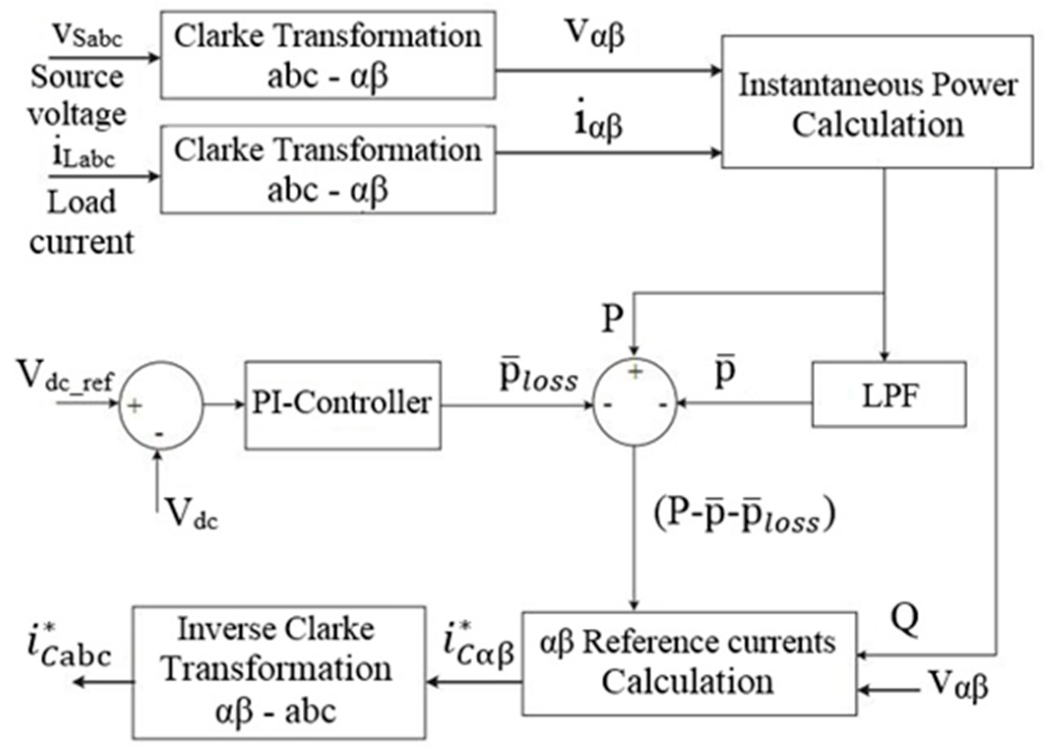
2.1.1. Harmonic Extraction

The harmonic extraction estimation is a major process which has a direct influence on the effective performance and accuracy of the shunt active power filter. There are several techniques to calculate the reference current, which are categorized under two approaches: time domain analysis and frequency domain analysis. The time domain analysis is a simple approach which relies on algebraic transformations and circuit analysis. It requires less calculation, and therefore shortens the control process. On the other hand, the frequency domain approach is more complex, requiring a large processing memory.
In this paper, the instantaneous reactive power theory (P-Q theory) in the time domain is presented and the simulation model is built using MATLAB/Simulink. Figure 2 shows the block diagram representation of the instantaneous reactive power theory. Basically, the instantaneous reactive power theory is based on the transformation of the a-b-c stationary reference coordinate to the 0-α-β rotating coordinate, which is known as a Clarke transformation. The source voltages and currents are transformed into 0-α-β components, as shown in the following expressions [35]
[ v 0 v α v β ] = 2 3   ·   [ 1 / 2 1 / 2 1 / 2 1 1 / 2 1 / 2 0 3 / 2 3 / 2 ] . [ v a v b v c ]
[ i 0 i α i β ] = 2 3   ·   [ 1 / 2 1 / 2 1 / 2 1 1 / 2 1 / 2 0 3 / 2 3 / 2 ] . [ i a i b i c ]
where va, vb, and vc refer to the three-phase voltages at the a-b-c coordinate, ia, ib, and ic represent the three-phase currents at the a-b-c coordinate, v0, vα, and vβ are the three-phase voltages at the 0-α-β coordinate, and i0, iα, and iβ refer to the three-phase currents at the 0-α-β coordinate.
The system considered in this paper is a three-phase three-wire system, therefore, a zero-sequence component is absent. In the α-β coordinate, the complex sum of the active and reactive powers (P and Q) can be represented by
S = P + j Q = v α β i α β = ( v α j v β ) ( i α + j i β ) = ( v α i α + v β i β ) + j ( v α i β v β i α )
where S is the complex power, P refers to the active power, Q represents the reactive power, and * is the complex conjugate.
Hence, the instantaneous active and reactive power components (P and Q) can be formed as follows [35]:
[ P Q ] = [ v α v β v β v α ] · [ i α i β ]
With the presence of nonlinear loads, the instantaneous active and reactive power components are decomposed of their AC and DC parts, as illustrated in Expressions (8) and (9), respectively. As shown in Figure 3, the DC part ( p ¯ ) of the instantaneous real power (P) represents the fundamental voltage and current components and corresponds to the power transferred from the source to the load, while the AC part ( p ˜ ) corresponds to the energy exchanged between the source and the load. The average or DC component of the instantaneous real power, which is the only power that should be provided by the three-phase AC source, is extracted by means of a high-order low-pass filter, as shown in Figure 2. With regard to the instantaneous reactive power component (Q), q ¯ and q ˜ , respectively, represent the fundamental component and harmonic component which are accountable for the energy circulation between the load phases [32].
P = p ¯ + p ˜
Q = q ¯ + q ˜
To generate the harmonic reference currents, the AC component ( p ˜ ) of the active power and the total reactive power (Q) are required. To recompose the voltage source inverter switching losses, and to preserve the DC-link voltage at the required level, the shunt active power filter consumes a small amount of real power ( p ¯ l o s s ) from the three-phase AC source or an external power supply. Therefore, the AC component ( p ˜ ) of the active power is measured as in Equation (10). Hence, the compensation reference currents in the α-β coordinates are calculated using Expression (11) and transformed to the a-b-c coordinates through an inverse transformation, as shown in Expression (12).
p ˜ = P p ¯ + p ¯ l o s s
[ i α i β ] = 1 v α 2 + v β 2 · [ v α v β v β v α ] · [ p ˜ Q ]
[ i a i b i c ] = 2 3   · [ 1 1 / 2 1 / 2         0 3 / 2   3 / 2 ] · [ i α i β ]

2.1.2. Current Control Technique

Throughout the phase of the SAPF’s current control design, several control methods have been applied in order to obtain the control pulses which are responsible for defining the operation of the filter switching states. Among these methods, the hysteresis band current is adopted in this study in order to generate the switching signals of the voltage source inverter. Through the different current control techniques, hysteresis current control is widely used due to its simple topology, fast response, accuracy and unconditioned stability.
In hysteresis current control, the current is kept in a predefined band of width, or the hysteresis band (HB), around the reference current, as shown in Figure 4. The actual current ( i S a , i S b ,   i S c ) is compared to the reference current ( i a , ,   i b ,   i c ) and the VSI switches are turned on and off in accordance with the error to maintain the actual current within the hysteresis band. When the current error exceeds the upper limit of the hysteresis band, the VSI output is switched off or vice versa. Typically, the DC voltage goes to the maximum value when the output current needs to increase, and to the minimum voltage when the current needs to decrease [36].

2.1.3. PI Controller

One of the crucial control phases of the shunt active power filter is to maintain a steady DC voltage level at the DC side of the voltage source inverter by means of DC-link voltage regulation. In general, power filters that employ voltage source inverters to generate the harmonic reference currents comprise of DC-link capacitors for energy storage. Hypothetically, the capacitor voltage should remain constant with no real power interchange between the filter and the AC grid. Practically, as aforementioned, the voltage source inverter consumes a small portion of real power for its switching operation [11]. Hence, to maintain a constant DC-link voltage and effectively compensate the harmonic current, a proportional–integral controller is used in the DC-link voltage control loop. The DC-link capacitor voltage (vdc) is compared with a reference DC voltage (vdc_ref) and the error (vdcvdc_ref) is served as the input to the PI controller, in which the steady-state error in the reference current signal tracking is eliminated. Figure 5 illustrates the inner current control loop and the outer voltage control loop of the DC voltage PI controller. The gains GPI (s) and GVSI represent the transfer functions of the PI controller and VSI, respectively. When the VSI switches are operated at a high frequency, the magnitudes of ( i S a , i S b ,   i S c ) are almost equal to the magnitudes of ( i a , ,   i b ,   i c ). Therefore, it can be assumed that the closed-loop current controller transfer function is unity.
G i ( s ) = i S a b c i a b c 1
where i Sabc represent the three-phase source currents; i abc refer to the three-phase reference current.
The values of the proportional gain (Kp) and integral gain (Ki) of the PI controller can be determined based on the step response of the closed-loop block diagram presented in Figure 6. Therefore, the transfer function of the controlled closed-loop of the DC voltage is derived as in Equation (14)
v d c v d c _ r e f = K p · K i C s 2 + K p C · s + K p · K i C
where v d c represents the DC voltage, v d c _ r e f is the DC reference voltage, K p refers to the proportional gain, K i is the integral gain, and C is the capacitor.
Since the transfer function of the DC voltage closed-loop control is a second-order transfer function, the proportional gain (Kp) and the integral gain (Ki) can be determined by equating the obtained open-loop transfer function in Equation (14) with the general form transfer function of a second-order system in Expression (15)
H ( s ) = ω n 2 s 2 + 2 ζ ω n s + ω n 2
where ω n is the damping natural frequency, and ζ refers to the damping factor.
By equating Equation (14) and Expression (15):
K p C = 2 ζ ω n and K p . K i C = ω n 2
Hence,
K p = 2 ζ ω n C and K i = ω n 2 ζ

3. Results and Discussion

The effectiveness of the proposed shunt active power filter control algorithm in the mitigation of current harmonics due to nonlinear loads is performed through a system simulation using the MATLAB/Simulink power tool. Figure 7 shows the complete Simulink model that consists of (i) a three-phase AC voltage source, (ii) a nonlinear load (a resistor connected to a three-phase universal diode bridge), and (iii) a shunt active power filter. For the simulation, the system parameters are listed in Table 1. The analysis of the SAPF’s effectiveness towards harmonic current elimination is examined under both balanced and unbalanced nonlinear load conditions.

3.1. Balanced System Nonlinear Load

Figure 8 shows the distorted three-phase source current (iS) and nonlinear load current (iL) waveforms under a balanced system and with a nonlinear load connected. The source current is distorted due to the nonlinearity behavior of the load. The fast Fourier Transform (FFT) analysis in Figure 9 shows the total harmonic distortion (THD) of the source current as 30.88%, which exceeds the IEEE harmonic standard limit [10].
In order to generate the compensation reference current ( i a ,   i b ,   i c ), the three-phase source voltage and current ( v a , v b ,   v c ,   and   i a ,   i b ,   i c ) are sensed and transformed from the a-b-c coordinates to the α-β coordinates ( v α , v β   and   i α ,   i β ) by means of a Clarke transformation. Figure 10, Figure 11 and Figure 12 show the Clarke transformation using Simulink and the transformed voltages and currents, respectively.
These voltages and currents ( v α , v β   and   i α ,   i β ) are used to calculate the instantaneous active and reactive power. The instantaneous active power is passed through a high-order low-pass filter to extract the average component of the active power that is needed, along with the total reactive power to generate the reference current in the α-β coordinates. Furthermore, the generated compensation reference currents ( i α ,   i β ) are transformed from the α-β frame to the a-b-c frame ( i a ,   i b ,   i c ). Figure 13, Figure 14 and Figure 15 show the Simulink model of the reference compensation currents’ generation, and their waveforms in the α-β and a-b-c frames, respectively.
Figure 16 shows the filtered source current and the load current waveforms after the shunt active power filter is connected to the point of common coupling and in parallel with the nonlinear load. The FFT analysis in Figure 17 shows that the Total Harmonic Distortion (THD) is reduced from 30.88% to only 1.18% which is a permissible value when compared with the 5% IEEE standard limit.

3.2. Unbalanced System Nonlinear Load

In this section, the performance of the proposed shunt active filter is examined under an unbalanced nonlinear load condition. A three-phase unbalanced R-L-C load which is connected to an uncontrolled universal diode bridge is considered. Figure 18 and Figure 19 show the source and load current waveforms, and the harmonic spectrum analysis for phase three before compensation, respectively. The total harmonic distortion of the system is 90.30%, which overrides the IEEE standards to a significant extent.
As shown in Figure 20, the distorted source current shown in Figure 18 is restored back to the sinusoidal waveform by means of the shunt active power filter. The source current’s FFT analysis in Figure 21 reveals that the shunt active power filter reduced the THD of the source current from 12.97% to 1.13%. Table 2 summarizes the source current’s total harmonic distortion results of the different conditions that have been considered in this study. The THD spectrum analysis of the proposed system has been compared with those of a few existing design methods available in the literature. The THD results, before compensation and after compensation, of the different methodologies are presented in Table 3. The tabular comparison reveals that the proposed system outperforms the other systems in the literature in harmonic current compensation for an unbalanced system and also occupies the third position for the balanced system.

4. Conclusions

Power quality studies are aimed at maintaining the power systems’ current and voltage as pure sinusoidal with a 1 p.u magnitude at a 1 p.u frequency and the phase shift of 120 degrees between the adjacent phases in a three-phase power system. Harmonic distortion is one of the power quality problems that are associated with nonlinear loads which draw non-sinusoidal currents and cause power quality deterioration. In this paper, the design aspects of a three-phase three-wire shunt active power filter, based on the instantaneous reactive power theory and hysteresis-PI control algorithm, have been simulated using the MATLAB/Simulink platform. The effectiveness of the filter in minimizing the current harmonics has been evaluated under balanced and unbalanced nonlinear load conditions. A comparative analysis with other algorithms has been performed to measure the proposed system performance compared with the other techniques in question.
The following conclusions have been made from the simulation analysis:
  • The proposed shunt active power filter was able to restore the distorted source current to its original sinusoidal waveform;
  • The investigations indicate that the proposed filter was able to minimize the current harmonics significantly less than the IEEE standard limits in both conditions;
  • The FFT spectrum analyses reveal that by employing the proposed SAPF, the THDs were reduced from 30.88% to 1.18 and from 12.97% to 1.13% for balanced and unbalanced systems, respectively;
  • The proposed shunt active power filter can effectively mitigate the harmonic current in both balanced and unbalanced power systems. However, the comparative study emphasized that the system performance surpassed the other states of art in the literature which are applied to balanced and unbalanced conditions.
This system can be experimentally established and verified through the development of a prototype model and the control algorithm can be extended in optimizing the PI controller parameters.

Author Contributions

Conceptualization, A.A.I.; Methodology, A.A.I., R.S.K., and Y.A.A.-T.; Software, A.A.I.; Validation, Y.A.A.-T. and R.S.K.; Formal analysis, A.A.I.; Resources, Y.A.A.-T. and R.S.K.; Writing—original draft preparation, A.A.I.; writing—review and editing, Y.A.A.-T. and R.S.K.; Supervision, Y.A.A.-T. and R.S.K.; Funding acquisition, Y.A.A.-T. and R.S.K. All authors have read and agreed to the published version of the manuscript.

Funding

This project was funded by the Deanship of Scientific Research (DSR), King Abdulaziz University, Jeddah, under grant No. (DG-061-135-1441). The authors, therefore, gratefully acknowledge DSR for their technical and financial support.

Acknowledgments

The first author would like to thank the deanship of graduate studies at King Abdulaziz University for the postgraduate scholarship.

Conflicts of Interest

The authors declare no conflict of interest.

References

  1. Nikum, K.; Saxena, R.; Wagh, A. Effect on power quality by large penetration of household non linear load. In Proceedings of the 2016 IEEE 1st International Conference on Power Electronics, Intelligent Control and Energy Systems (ICPEICES), Delhi, India, 4–6 July 2016; pp. 1–5. [Google Scholar]
  2. Monteiro, F.; Monteiro, S.; Tostes, M.; Bezerra, U. Using True RMS Current Measurements to Estimate Harmonic Impacts of Multiple Nonlinear Loads in Electric Distribution Grids. Energies 2019, 12, 4132. [Google Scholar] [CrossRef]
  3. Witherden, M.S.; Rayudu, R.; Rigo-Mariani, R. The influence of nonlinear loads on the power quality of the New Zealand low voltage electrical power distribution network. In Proceedings of the 2010 20th Australasian Universities Power Engineering Conference, Christchurch, New Zealand, 5–8 December 2010; pp. 1–6. [Google Scholar]
  4. Rakpenthai, C.; Uatrongjit, S.; Watson, N.R.; Premrudeepreechacharn, S. On harmonic state estimation of power system with uncertain network parameters. IEEE Trans. Power Syst. 2013, 28, 4829–4838. [Google Scholar] [CrossRef]
  5. Olivares, D.E.; Mehrizi-Sani, A.; Etemadi, A.H.; Cañizares, C.A.; Iravani, R.; Kazerani, M.; Hajimiragha, A.H.; Gomis-Bellmunt, O.; Saeedifard, M.; Palma-Behnke, R. Trends in microgrid control. IEEE Trans. Smart Grid 2014, 5, 1905–1919. [Google Scholar] [CrossRef]
  6. Choudhury, S.R.; Das, A.; Anand, S.; Tungare, S.; Sonawane, Y. Adaptive shunt filtering control of UPQC for increased nonlinear loads. Iet Power Electron. 2018, 12, 330–336. [Google Scholar] [CrossRef]
  7. Jarwar, A.R.; Soomro, A.M.; Memon, Z.A.; Odhano, S.A.; Uqaili, M.A.; Larik, A.S. High dynamic performance power quality conditioner for AC microgrids. Iet Power Electron. 2018, 12, 550–556. [Google Scholar] [CrossRef]
  8. Chen, C.-I.; Lan, C.-K.; Chen, Y.-C.; Chen, C.-H. Adaptive Frequency-Based Reference Compensation Current Control Strategy of Shunt Active Power Filter for Unbalanced Nonlinear Loads. Energies 2019, 12, 3080. [Google Scholar] [CrossRef] [Green Version]
  9. IEEE Recommended Practices and Requirements for Harmonic Control in Electrical Power Systems. IEEE Std 519-1992 1993. [CrossRef]
  10. IEEE. IEEE Recommended Practice and Requirements for Harmonic Control in Electric Power Systems. Available online: https://edisciplinas.usp.br/pluginfile.php/1589263/mod_resource/content/1/IEE%20Std%20519-2014.pdf (accessed on 15 January 2020).
  11. Hoon, Y.; Radzi, M.; Amran, M.; Hassan, M.K.; Mailah, N.F. Control algorithms of shunt active power filter for harmonics mitigation: A review. Energies 2017, 10, 2038. [Google Scholar] [CrossRef] [Green Version]
  12. Pan, D.; Ruan, X.; Bao, C.; Li, W.; Wang, X. Capacitor-Current-Feedback Active Damping With Reduced Computation Delay for Improving Robustness of LCL-Type Grid-Connected Inverter. IEEE Trans. Power Electron. 2014, 29, 3414–3427. [Google Scholar] [CrossRef]
  13. Liserre, M.; Blaabjerg, F.; Hansen, S. Design and control of an LCL-filter based three-phase active rectifier. In Proceedings of the Conference Record of the 2001 IEEE Industry Applications Conference. 36th IAS Annual Meeting (Cat. No.01CH37248), Chicago, IL, USA, 30 September–4 October 2001; pp. 299–307. [Google Scholar]
  14. Tang, Y.; Loh, P.C.; Wang, P.; Choo, F.H.; Gao, F. Exploring Inherent Damping Characteristic of LCL-Filters for Three-Phase Grid-Connected Voltage Source Inverters. IEEE Trans. Power Electron. 2012, 27, 1433–1443. [Google Scholar] [CrossRef]
  15. Wu, W.; He, Y.; Blaabjerg, F. An LLCL power filter for single-phase grid-tied inverter. IEEE Trans. Power Electron. 2011, 27, 782–789. [Google Scholar] [CrossRef]
  16. Xu, J.; Yang, J.; Ye, J.; Zhang, Z.; Shen, A. An LTCL filter for three-phase grid-connected converters. IEEE Trans. Power Electron. 2013, 29, 4322–4338. [Google Scholar] [CrossRef]
  17. Anzalchi, A.; Moghaddami, M.; Moghaddasi, A.; Sarwat, A.I.; Rathore, A.K. A new topology of higher order power filter for single-phase grid-tied voltage-source inverters. IEEE Trans. Ind. Electron. 2016, 63, 7511–7522. [Google Scholar] [CrossRef]
  18. Fang, J.; Li, X.; Tang, Y. A review of passive power filters for voltage-source converters. In Proceedings of the 2016 Asian Conference on Energy, Power and Transportation Electrification (ACEPT), Singapore, 25–27 October 2016; pp. 1–6. [Google Scholar]
  19. Srivastava, G.D.; Kulkarni, R.D. Design, simulation and analysis of Shunt Active Power Filter using instantaneous reactive power topology. In Proceedings of the 2017 International Conference on Nascent Technologies in Engineering (ICNTE), Navi Mumbai, India, 27–28 January 2017; pp. 1–6. [Google Scholar]
  20. Swain, S.D.; Ray, P.K.; Mohanty, K.B. Improvement of power quality using a robust hybrid series active power filter. IEEE Trans. Power Electron. 2016, 32, 3490–3498. [Google Scholar] [CrossRef]
  21. Monroy-Morales, J.; Campos-Gaona, D.; Hernández-Ángeles, M.; Peña-Alzola, R.; Guardado-Zavala, J. An active power filter based on a three-level inverter and 3D-SVPWM for selective harmonic and reactive compensation. Energies 2017, 10, 297. [Google Scholar] [CrossRef] [Green Version]
  22. Adam, G.; Stan, A.G.; Livinţ, G. An adaptive hysteresis band current control for three phase shunt active power filter U sing Fuzzy logic. In Proceedings of the 2012 International Conference and Exposition on Electrical and Power Engineering, Iasi, Romania, 25–27 October 2012; pp. 324–329. [Google Scholar]
  23. Akagi, H.; Kanazawa, Y.; Fujita, K.; Nabae, A. Generalized theory of instantaneous reactive power and its application. Electr. Eng. Jpn. 1983, 103, 58–66. [Google Scholar] [CrossRef]
  24. Artemenko, M.Y.; Mykhalskyi, V.M.; Polishchuk, S.Y.; Chopyk, V.V.; Shapoval, I.A. Modified Instantaneous Power Theory for Three-Phase Four-Wire Power Systems. In Proceedings of the 2019 IEEE 39th International Conference on Electronics and Nanotechnology (ELNANO), Kyiv, Ukraine, 16–18 April 2019; pp. 600–605. [Google Scholar]
  25. Chang, G.W.; Tai-Chang, S. A novel reference compensation current strategy for shunt active power filter control. IEEE Trans. Power Deliv. 2004, 19, 1751–1758. [Google Scholar] [CrossRef]
  26. Li, Z.; Hu, T.; Abu-Siada, A. A minimum side-lobe optimization window function and its application in harmonic detection of an electricity gird. Energies 2019, 12, 2619. [Google Scholar] [CrossRef] [Green Version]
  27. Wada, K.; Fujita, H.; Akagi, H. Considerations of a shunt active filter based on voltage detection for installation on a long distribution feeder. IEEE Trans. Ind. Appl. 2002, 38, 1123–1130. [Google Scholar] [CrossRef]
  28. Maza-Ortega, J.M.; Rosendo-Macías, J.A.; Gomez-Exposito, A.; Ceballos-Mannozzi, S.; Barragan-Villarejo, M. Reference current computation for active power filters by running DFT techniques. IEEE Trans. Power Deliv. 2010, 25, 1986–1995. [Google Scholar] [CrossRef]
  29. Mehrasa, M.; Pouresmaeil, E.; Akorede, M.F.; Jørgensen, B.N.; Catalão, J.P. Multilevel converter control approach of active power filter for harmonics elimination in electric grids. Energy 2015, 84, 722–731. [Google Scholar] [CrossRef]
  30. Kanjiya, P.; Khadkikar, V.; Zeineldin, H.H. A noniterative optimized algorithm for shunt active power filter under distorted and unbalanced supply voltages. IEEE Trans. Ind. Electron. 2012, 60, 5376–5390. [Google Scholar] [CrossRef]
  31. Chaoui, A.; Gaubert, J.P.; Krim, F.; Champenois, G. PI controlled three-phase shunt active power filter for power quality improvement. Electr. Power Compon. Syst. 2007, 35, 1331–1344. [Google Scholar] [CrossRef]
  32. Afonso, J.L.; Couto, C.; Martins, J.S. Active filters with control based on the pq theory. IEEE Ind. Electron. Soc. Newsl. 2000, 47, 5–10. [Google Scholar]
  33. Ouchen, S.; Gaubert, J.-P.; Steinhart, H.; Betka, A. Energy quality improvement of three-phase shunt active power filter under different voltage conditions based on predictive direct power control with disturbance rejection principle. Math. Comput. Simul. 2019, 158, 506–519. [Google Scholar] [CrossRef]
  34. Hoon, Y.; Radzi, M.; Amran, M.; Zainuri, M.; Atiqi, M.A.; Zawawi, M.A.M. Shunt Active Power Filter: A Review on Phase Synchronization Control Techniques. Electronics 2019, 8, 791. [Google Scholar] [CrossRef] [Green Version]
  35. Ali, I.; Sharma, V.; Kumar, P. A comparison of different control techniques for active power filter for harmonic elimination and enhancement of power quality. In Proceedings of the 2017 International Conference on Energy, Communication, Data Analytics and Soft Computing (ICECDS), Chennai, India, 1–2 August 2017; pp. 2565–2570. [Google Scholar]
  36. Omeiri, A.; Zoubir, C. Hysteresis Control for Shunt Active Power Filter under Unbalanced Three-Phase Load Conditions. J. Electr. Eng. 2015, 2015, 976–984. [Google Scholar]
  37. Mahaboob, S.; Ajithan, S.; Jayaraman, S. Optimal design of shunt active power filter for power quality enhancement using predator-prey based firefly optimization. Swarm Evol. Comput. 2018, 44. [Google Scholar] [CrossRef]
  38. Sundaram, E.; Venugopal, M. On design and implementation of three phase three level shunt active power filter for harmonic reduction using synchronous reference frame theory. Int. J. Electr. Power Energy Syst. 2016, 81, 40–47. [Google Scholar] [CrossRef]
  39. Chaoui, A.; Gaubert, J.-P.; Krim, F. Power quality improvement using DPC controlled three-phase shunt active filter. Electr. Power Syst. Res. 2010, 80, 657–666. [Google Scholar] [CrossRef]
  40. Sakthivel, A.; Vijayakumar, P.; Senthilkumar, A.; Lakshminarasimman, L.; Paramasivam, S. Experimental investigations on ant colony optimized PI control algorithm for shunt active power filter to improve power quality. Control Eng. Pract. 2015, 42, 153–169. [Google Scholar] [CrossRef]
  41. Parithimar Kalaignan, T. Power Quality Enhancement by Minimizing Current Harmonics Using Soft Computing Based Shunt Active and Hybrid Filters. Available online: http://hdl.handle.net/10603/141027 (accessed on 15 January 2020).
  42. Senthilnathan, N.; Manigandan, T. Design and development of three phase shunt active filter with balanced and unbalanced supply. Int. J. Electr. Eng. 2012, 5, 275–291. [Google Scholar]
  43. Chelli, Z.; Toufouti, R.; Omeiri, A.; Saad, S. Hysteresis control for shunt active power filter under unbalanced three-phase load conditions. J. Electr. Comput. Eng. 2015, 2015, 15. [Google Scholar] [CrossRef]
Figure 1. Three-phase three-wire shunt active power filter configuration.
Electronics 09 00637 g001
Figure 2. Block diagram of the active and reactive power theory.
Electronics 09 00637 g002
Figure 3. Power components of P-Q theory.
Electronics 09 00637 g003
Figure 4. Hysteresis current control technique.
Electronics 09 00637 g004
Figure 5. Cascade closed loops of current and voltage.
Electronics 09 00637 g005
Figure 6. DC voltage control closed-loop.
Electronics 09 00637 g006
Figure 7. Simulink model of the proposed shunt active power filter (SAPF).
Electronics 09 00637 g007
Figure 8. Before compensation (a) source current; (b) load current.
Electronics 09 00637 g008
Figure 9. Before compensation source current FFT analysis.
Electronics 09 00637 g009
Figure 10. Simulink model of the Clarke transformation (a) voltage transformation; (b) current transformations.
Electronics 09 00637 g010
Figure 11. Transformed voltages (a) v α ; (b)   v β .
Electronics 09 00637 g011
Figure 12. Transformed currents (a) i α ; (b) i β .
Electronics 09 00637 g012
Figure 13. Simulink reference current generation in (a) the α-β frame; (b) the a-b-c frame.
Electronics 09 00637 g013
Figure 14. Compensation currents (a) i α ; (b) i β .
Electronics 09 00637 g014
Figure 15. Transformed reference currents (a) i a ; (b) i b ; (c) i c .
Electronics 09 00637 g015
Figure 16. After compensation current (a) source; (b) load.
Electronics 09 00637 g016
Figure 17. After compensation source current FFT analysis.
Electronics 09 00637 g017
Figure 18. Before compensation unbalanced system (a) source current; (b) load current.
Electronics 09 00637 g018
Figure 19. Before compensation unbalanced system source current FFT analysis.
Electronics 09 00637 g019
Figure 20. After compensation unbalanced system (a) source current; (b) load current.
Electronics 09 00637 g020
Figure 21. After compensation unbalanced system source current FFT analysis.
Electronics 09 00637 g021
Table 1. System parameters.
ParameterValue
AC source voltage380 VPh-Ph
Frequency50 Hz
Source impedanceRS = 0.1 Ω, LS = 10 mH
Filter impedanceRS = 0.0 Ω, LS = 1.0 mH
DC-link capacitor1000 μF, 400 V
KP1.2
KI20
Table 2. Source current total harmonic distortions (THDs).
No. Load Description% Source Current THD
1Balanced system nonlinear load without SAPF30.88
2Balanced system nonlinear load with SAPF1.18
3Unbalanced system nonlinear load without SAPF12.97
4Unbalanced system nonlinear load with SAPF1.13
Table 3. %THD comparison.
Method%THD%Compensation
Before Compensation After Compensation
Balance SystemUnbalanced SystemBalance SystemUnbalanced SystemBalanced
System
Unbalanced
System
Proposed PI30.8812.971.181.1396.1891.28
PPFO [37]11.442711.901.912.0683.3182.69
FO [37]11.442711.901.932.1883.1381.68
PSO [37]11.442711.902.113.4281.5671.26
HSO [37]11.442711.902.232.8980.5175.71
SRF [38]29.19-0.90-96.92-
DPC [39]27.48-0.91-96.69-
Conv. PI [40]28.01-3.88-86.15-
BF PI [40] 28.01-3.71-86.75-
ACO PI [40]28.01-3.72-86.72-
ZN [41]31.66-7.57-76.09-
GA [41]31.66-4.56-85.6-
PSO [41]31.66-4.55-85.63-
SCS [42]20.75-1.27-93.88-
Novel P-Q [43]-12.55-1.89-84.94

