Article

Cyber-Physical Co-Simulation of Shipboard Integrated Power System Based on Optimized Event-Driven Synchronization

National Key Laboratory of Science and Technology on Vessel Integrated Power System, Naval University of Engineering, Wuhan 430033, China
*
Author to whom correspondence should be addressed.
Electronics 2020, 9(3), 540; https://doi.org/10.3390/electronics9030540
Submission received: 21 February 2020 / Revised: 13 March 2020 / Accepted: 23 March 2020 / Published: 24 March 2020
(This article belongs to the Section Power Electronics)

Abstract

:
As the energy management system (EMS) participates in the closed-loop control of shipboard integrated power system (IPS), the information network of EMS is closely coupled with the power system and its characteristics affect power system performance significantly. To study the close-coupling relationship between the two systems, a cyber–physical co-simulation platform based on the high level architecture (HLA) framework is constructed in this paper. The proposed platform uses PSCAD and OPNET to simulate shipboard power system and information network respectively, and utilizes OPNET HLA nodes and PSCAD user-defined modules to implement co-simulation interfaces. In order to achieve a higher co-simulation precision without impairing efficiency, an optimized event-driven co-simulation synchronization method is also proposed. By pre-defining power system synchronization points and detecting information network synchronization points in the co-simulation process, both systems can be synchronized in time and the synchronization error is eliminated. Furthermore, the co-simulation efficiency is also improved by optimizing the data transmission in the synchronization process. A co-simulation model of shipboard power distribution network protection based on CAN bus communication is built and analyzed. Simulation results show that the proposed co-simulation platform and synchronization method are feasible and effective.

1. Introduction

With the wide application of shipboard integrated power system (IPS) in large ships, the management of shipboard electric energy generation, distribution and consumption is increasingly complex. It is necessary to apply an energy management system (EMS) based on high-speed information network to monitor and manage the various electric equipment and the operation state of the whole IPS. In the future, EMS will participate in the real-time closed-loop control of IPS, which will result in the close-coupling relationship between power system and information network. In order to prevent cascading failures and improve system safety and stability in such systems, it is critical to consider not only the respective characteristics of both power system and information network, but also the close-coupling relationship between them. The conventional power system simulation tools are no longer sufficient for such comprehensive analysis, so it is necessary to regard the whole system as a cyber–physical power system (CPPS) and design co-simulation tools which can reveal the fundamental principle of “data flow” controlling “energy flow” in such systems [1,2,3].
In recent years, dozens of co-simulation platforms for CPPS have been built by expanding existing power system or information network simulators [4,5], connecting several simulators via middleware [6,7,8], integrating simulators under a general co-simulation framework [9,10,11], etc. Researches in fields such as wide area control network and intelligent power substation have been done based on these platforms. But most of the current CPPS researches are aimed at land-based power systems, and only a few of them take shipboard CPPS as a research subject. As shipboard CPPS is relatively smaller and simpler in structure, factors such as physical distance or network bandwidth do not affect it as much as land-based CPPS. But shipboard CPPS contains a large number of network-controlled power electronic devices, making it more vulnerable to cascading failures caused by network malfunctions. So, it is essential to take a different approach in the research of shipboard CPPS co-simulation, which entails more specific modeling of network protocols and higher co-simulation precision.
The co-simulation platform structure and synchronization method are two key factors in shipboard CPPS research. In the aspect of platform structure, building a platform by simply extending an existing simulator is not advisable, as the extension cannot accurately represent the characteristics of power system or information network. Connecting simulators through ad hoc middleware is inflexible as the middleware need to be redesigned entirely when the platform is modified. For instance, VPNET (VTB and OPNET) [12,13,14] is a shipboard CPPS co-simulation platform which uses VTB (Virtual Test Bed) and OPNET as power system and information network simulators. As VTB is not a commonly used power system simulator, and the ad hoc middleware makes it hard to incorporate other power system simulators in the platform, it is inconvenient to make use of existing power system models and do CPPS research on the platform. Compared to such platform structures, integrating simulators under the same co-simulation framework is a preferable choice, as both the power system and the information network can be simulated accurately, and the platform is flexible and extendable as all the simulators use unified interfaces provided by the framework. The high level architecture (HLA) is such a general-purpose framework in the field of modeling and simulation [15,16]. In the field of CPPS co-simulation research, HLA has been widely applied in platforms and researches such as EPOCHS (Electric power and communication synchronizing simulator) [17,18], INSPIRE (Integrated co-simulation of power and ICT systems for real-time evaluation) [19,20,21], wide area network protection research [22,23,24], etc. But it has not been applied in shipboard CPPS co-simulation research yet.
The synchronization method is also critical in co-simulation as it affects both accuracy and efficiency of the co-simulation. The fundamental principles of power system and information network simulations are inherently different. The power system simulation is implemented in the form of differential equation iterations, usually with fixed time step, while the information network simulation is event-based, the simulation events take place at random time points. As a result, the most critical factor of co-simulation is the choosing of synchronization points, as it affects both accuracy and efficiency of co-simulation. There are now two mainstream synchronization methods: fixed-step synchronization [17] and global event driven synchronization [25]. Both methods have their advantages and drawbacks. The fixed-step method is relatively more efficient and easier to implement, but its pre-defined synchronization points make it impossible to process every co-simulation event in time, which may lead to errors. As for the global event driven method, it processes every event in both power system and information network simulation instantly through a global event scheduler, thus achieving a very high level of accuracy. But as a large portion of such events are not interaction requests, processing them is unnecessary and will greatly decrease co-simulation efficiency. In order to improve the overall performance of the co-simulation, it is necessary to propose a co-simulation synchronization method which can run accurately with desirable efficiency.
In this paper, a shipboard CPPS co-simulation platform based on HLA framework is built. The platform adopts OPNET and PSCAD/EMTDC as its information network and power system simulators respectively. By applying the OPNET HLA node and designing the PSCAD user-defined module and the co-simulation controller, the two simulators run seamlessly together. Based on the designed platform, an optimized event-driven synchronization method which balances the co-simulation efficiency and accuracy is proposed. A model of shipboard low voltage AC distribution network protection based on CAN bus communication is built in the co-simulation platform. Both the platform and the synchronization method are validated by simulation results. The paper is organized as follows: in Section 2, the overall structure of the co-simulation platform is introduced. Section 3 details the optimized synchronization method. Section 4 illustrates the OPNET and PSCAD interfaces design in co-simulation. The platform and synchronization method are validated through simulation in Section 5 and conclusions and future works are presented in Section 6.

2. Structure of HLA-Based Cyber–Physical Co-Simulation Systems

2.1. HLA Framework and Run Time Infrastructure (RTI)

An HLA-based co-simulation system is typically comprised of a federation and several federates. The federation represents the co-simulation system which contains multiple simulation platforms, and the federate represents all the simulation programs participating in the federation [26]. The HLA framework facilitates the co-simulation through RTI (Run Time Infrastructure). By calling the standard interfaces provided by RTI, co-simulation federates can implement functions such as data exchange, time synchronization, etc. The structure of a typical co-simulation system is shown in Figure 1.
A typical co-simulation platform based on HLA and RTI includes the RTI executive, the federation executive, the RTI library (libRTI) and simulation platforms acting as federates. As a global process, the RTI executive manages the creation and destruction of federation executives. Each federation executive manages a federation, it controls the joining and resigning process of involved federates, and also enables data exchange between them. Through libRTI, RTI provides services for co-simulation in six management areas, which are federation management, declaration management, time management, object management, ownership management and data distribution management. By calling libRTI, federates can implement functions such as creating and destroying federation, joining and resigning from federation execution, and data exchange with other federates. Based on such functions, a co-simulation system can be built.

2.2. Cyber–Physical Co-Simulation System Strcture

Based on HLA RTI interface and relevant interfaces in OPNET and PSCAD, a shipboard CPPS co-simulation system is designed as in Figure 2.
The co-simulation system consists of power system electromagnetic transient simulation platform PSCAD, information network simulation platform OPNET Modeler, co-simulation controller based on C++ and RTI. In co-simulation, the function of RTI is illustrated in the previous section, which is providing interfaces for co-simulation federates. OPNET implements the simulation of EMS information network, within which the EMS control strategies can be carried out. It participates in co-simulation via its ad hoc HLA node. PSCAD implements the power system part of co-simulation, its data exchange with outside software is implemented through a user-defined module. As PSCAD cannot directly call C++-based RTI library functions in its modules, a co-simulation controller based on C++ is designed in the system. The controller implements co-simulation functions (such as federation control) by directly calling RTI functions, and exchange simulation data with PSCAD user-defined module via TCP/IP protocol, so that the PSCAD simulation can indirectly join the simulation federation. To summarize, the designed co-simulation federation contains two federates, which are OPNET and the co-simulation controller acting as the substitute federate of PSCAD.

3. Optimized Event-Driven Co-Simulation Synchronization Method

3.1. Optimized Event-Driven Synchronization Method

In order to unify the description of power system and information network simulation process, the power system simulation can also be described as an event-based simulation, in which each iteration is regarded as a simulation event. Thus, the power system and information network simulation events in co-simulation can be presented as in Figure 3. It can be seen that power system events (P1–P10) are evenly distributed, as they represent the fixed-step iterations in power system simulation. Information network events (C1–C3) are randomly distributed as the simulation is event-driven. According to their roles in co-simulation synchronization, the events in both systems can be divided into two categories: interaction requests and common events. An interaction request means through the event, the simulation request to interact with the other simulation through synchronization. For example, the power system request to upload its monitor data to the information network, or the information network request to send EMS control commands to the power system. Apparently, interaction requests should be processed in time in co-simulation synchronization, otherwise the co-simulation precision will be compromised. Except for interaction requests, other simulation events can be categorized as common events. They only affect the running of the local simulation, and do not need to be processed in the synchronization process. In Figure 3, events P1, P4, P7, P10, C1 and C2 are set as interaction requests (denoted by solid lines), and other events are set as common events (denoted by dashed lines). It should be noted that the power system interaction request is evenly distributed with the same interval, because in actual power system monitoring process, data is periodically acquired at a certain frequency. Information network interaction requests distribute randomly due to network delay.
There are two conventional co-simulation synchronization methods: fixed-step synchronization and global event-driven synchronization. The principle of conventional fixed-step synchronization is shown in Figure 4. In fixed-step synchronization, all the synchronization points are pre-defined. By properly set the parameters, the method can process power system interaction requests in time and accurately present the periodical monitoring process of power system. But as all the synchronization points are pre-defined, the random information network interaction request cannot always be processed in time. Thus, co-simulation error is induced, as shown in Figure 4.
As for the global event-driven synchronization method, an event list of all simulation events is maintained through the process of co-simulation, and synchronization is performed whenever an event occurs, as shown in Figure 5. But as mentioned before, common events in simulation, which take up a large portion of all events, do not need to be processed in synchronization. Thus, the corresponding synchronization points are excessive, processing them will waste a lot of calculation resource and significantly compromise co-simulation efficiency.
In order to solve the precision and efficiency problems in co-simulation synchronization, an optimized event-driven synchronization method is proposed. The principle of the proposed method is as follows: Firstly, the interaction requests from both power system and information network simulation are identified and marked. In power system simulation, the interaction requests are evenly distributed, so they can be marked before co-simulation according to power system monitoring frequency. For information network simulation, as the interaction requests occur randomly, they cannot be marked before co-simulation. Thus, the synchronization method is designed to accurately detect them in the process of co-simulation. In order to do so, an “event filter” is implemented in the information network simulation. According to specific criteria in each co-simulation case, the event filter can judge whether an event is an interaction request, thus synchronization can be executed accordingly. In the co-simulation process, synchronization is executed whenever pre-defined power system interaction requests occurs, as P1, P4, P7 and P10 in Figure 6. At the same time, co-simulation also monitors information network interaction requests through event filters, if an information network event passes the event filter and is identified as interaction request, as C1 and C2 in Figure 6, synchronization will also be executed. As a result, synchronization only takes place at the time of interaction requests in the proposed method. Thus, all the interaction requests can be processed timely, and no excessive synchronization is performed.
In order to implement the optimized event-driven synchronization method in the proposed co-simulation platform, the synchronization process of the platform is designed as in Figure 7.
In Figure 7, t1–t2 and t3–t4 are two monitoring cycles of power system simulation, thus t1–t4 are 4 power system interaction requests. During initiation, such interaction requests are stored as pre-defined synchronization points in RTI. Assuming N random information network interaction request take place at te1, te2, … teN between t1 and t2, then the synchronization process is as follows:
  • At time t1, RTI sends PSCAD simulation data to OPNET and set t2 as the target time of OPNET simulation, then advance the OPNET simulation clock. Meanwhile PSCAD pauses at t1.
  • At time te1, an OPNET interaction request is detected, the OPNET simulation pauses.
  • Through RTI, OPNET simulation data and simulation time te1 is transmitted to PSCAD, where te1 is set as the next target time of PSCAD simulation.
  • PSCAD simulation clock is advanced to te1 and then pauses.
  • PSCAD send back power system simulation data back to OPNET. Upon receiving the data, OPENT resumes running, and its target time is still t2.
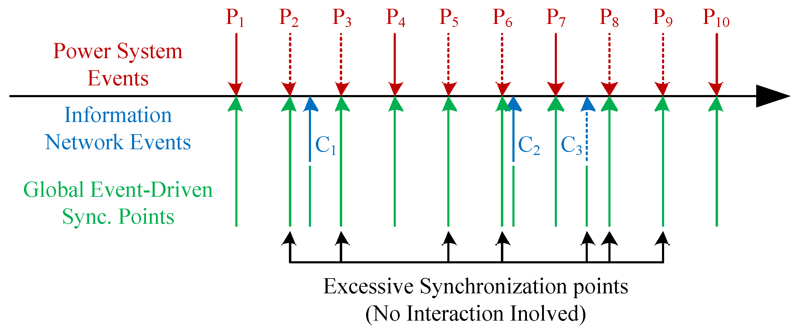
  • There are two possible cases after OPNET resumes running. First, another interaction request may be detected before t2. In this case, OPNET simulation pauses, the process goes back to step 3, and synchronization is performed through step 3 to 5 at the time of the newly detected interaction request (as the red dashed lines in Figure 7). Then the process comes back to this step again. Second, if OPNET reaches t2 without detecting any new interaction requests, it means all the interaction requests between t1 and t2 have been processed. OPNET pauses at t2 and the process proceed to step 7. (as in the case of teN in Figure 7).
  • After pausing at t2, OPNET send simulation data and time t2 to PSCAD.
  • Upon receiving the OPNET data, PSCAD runs until t2 based on the data received in step 3, then pauses simulation and send simulation data to RTI. This co-simulation cycle is then completed, and the next cycle is ready to begin.
To summarize, the whole synchronization process can be divided into 3 parts. The first part is step 1 and step 2, which is the start of the cycle. In this part, the synchronization cycle starts and OPNET simulation clock is advanced to the first detected interaction request. The second part is step 3 to step 6, which is the processing of interaction requests. This part repeats itself and performs synchronization when an interaction request is detected. The last part is step 7 and step 8, which is the end of the cycle. This part takes place and finishes the cycle operation after all the interaction requests detected within the cycle have been processed. If no information network interaction request is detected during the power system sampling cycle, as in t3–t4 in Figure 7, then synchronization just takes place at the pre-defined synchronization points, which are t3 and t4.
In the proposed method, interaction requests from both power system and information network simulations can be processed in time. The co-simulation accuracy is greatly improved compared to the conventional fixed-step synchronization method. As mentioned before, the accuracy depends on the timely processing of interaction requests. By comparing Figure 5 and Figure 6, it can be seen that in both the proposed method and the global event driven method, all the interaction requests can be processed in time. Therefore, the proposed method reaches the same level of accuracy with the global event driven method. Moreover, by only processing the interaction requests, the proposed method also eliminates unnecessary synchronization points in the global even driven method and significantly improves co-simulation efficiency.

3.2. Optimization of Co-Simulation Data Exchange

In order to further improve co-simulation efficiency, the data exchange process in synchronization is also optimized. In the proposed mothed, unidirectional data transmission is sufficient for each synchronization point. When dealing with power system interaction requests, co-simulation only needs to transmit power system sampling data to information network. When an information network interaction request occurs, only EMS control commands need to be transmitted from information network to power system. Conventionally, as the co-simulation does not differentiate interaction requests from power system and information network, the data exchange at every synchronization point is bidirectional, as shown in Figure 8. Such an operation mode is inefficient and will waste much system resource, especially when co-simulation deals with large systems or adapts a small synchronization step.
In the proposed synchronization method, as power system interaction requests are pre-defined and information network interaction requests are detected in the simulation process, the two types of interaction requests are dealt with respectively, which makes it possible to define different data transmission behaviors for each type of interaction requests and optimize the overall performance of co-simulation. Specifically, the data transmission in step 5 in Figure 7 is replaced with sending a “resume running” signal from PSCAD to OPNET. The data transmission in step 7 is also replaced by a “cycle finished” signal from OPNET to PSCAD correspondingly. Thus, the data exchange in synchronization is simplified from bidirectional to unidirectional, as shown in Figure 9. As a result, the overall data transmission load of co-simulation is cut in half, the co-simulation efficiency is greatly improved without impairing its accuracy.

4. Implementation of OPNET and PSCAD Interfaces

4.1. OPNET Interface Based on HLA Node

The OPNET platform is designed to be highly compatible with the HLA framework. It provides users with ad hoc HLA nodes and corresponding configuration files, with which OPNET simulations can be easily incorporated and synchronized with RTI. Through HLA nodes, OPNET implements data exchange with RTI programs under the principle of “packet mapping”, the process of which is shown in Figure 10.
A typical OPNET simulation model can be hierarchically divided into network model, node model and process model. The process models within the same node model are connected via packet streams. If one process model sends a packet to a port connected with a packet stream, the packet is then transmitted to the process model on the other end of the packet stream [27]. When the simulation contains an HLA node, process models can register a virtual port for HLA use and specify the mapping relations between data fields in OPNET packets and parameters in RTI interactive object instances through configuration files. As OPNET process models use Finite State Machines (FSM) to implement specific functions, an FSM model is designed as in Figure 11 to implement the synchronization between OPNET and RTI.
As shown in Figure 11, after initiation, the FSM enters idle state and waits for events. When an information network interaction request occurs, the process needs to send information network simulation data (EMS control command and simulation time) to RTI. In order to transfer the data, the process generates a packet and sends it through the virtual port. The packet will be mapped into an interactive object instance which will be received by the RTI executive. By reading the parameters in the instance, the RTI executive can receive the data. After sending the data, the process waits for the “Resume Running” signal from RTI and goes back to idle state to proceed. When simulation reaches a pre-defined synchronization point, which means a power system interaction request, it first sends “Cycle Finished” signal to RTI, notifying PSCAD that OPNET has completed the previous co-simulation cycle, and waits for PSCAD to complete the same cycle and send the data back to OPNET. After receiving the data, the process model goes back to idle state and starts a new co-simulation cycle.

4.2. PSCAD Interface Based on User-Defined Module and Socket

As PSCAD cannot directly participate in HLA-based co-simulation, in the proposed co-simulation system an interface comprised of PSCAD user-defined module, Socket communication and C++-based co-simulation controller is designed to facilitate the PSCAD simulation’s indirect participation in HLA-based co-simulations. The structure of the interface is shown in Figure 12.
In PSCAD simulation, user-defined modules can be directly connected to measurers and get power system data via its input ports. After getting the data, the module integrates them into a packet and sends it to co-simulation controller via Socket communication. Likewise, after receiving control data from the co-simulation controller, the module analyzes the packet, generates control commands, and sends the commands to corresponding power system equipment through its output ports. In order to implement the synchronization between PSCAD and RTI, the running process of the user-defines module is shown as the flow chart in Figure 13.
As a part of PSCAD fixed-step simulation, the code of user-defined module runs every time a simulation cycle starts. Firstly, the module decides its following actions based on the simulation time. If the simulation time is 0, meaning it is the first cycle of the PSCAD simulation, then the initiation function is called and the Socket connection is established. Then the module further judges if the current time is a power system synchronization point or an information network synchronization point. If it is a power system synchronization point, then the module sends PSCAD simulation data to OPNET through RTI as in step 1 in Figure 7. Otherwise if it is an information network synchronization point, it sends the “Resume Running” signal to OPNET as in step 5 in Figure 7. If it is not a synchronization point, the module does nothing. After sending, the module calls the socket receiving function and starts waiting for response packet from the co-simulation controller. The function will keep running until a packet from co-simulation controller is received or the waiting time limit is exceeded. As a PSCAD simulation cycle cannot be completed unless all the modules finish operating, the waiting process enables the PSCAD simulation to pause until an external packet is received. If the module receives an OPNET command with simulation time, it means the next synchronization point is an information network synchronization point, the module will set the synchronization point accordingly and finishes the cycle’s operation. Instead, if a “Cycle Finished” signal is received, it means the next synchronization point is a power system synchronization point, the module directly ends the cycle’s operation. If a communication error occurs and the module receive the wrong type of packet or reaches timeout while waiting, the whole co-simulation will end and output the error message.

5. Simulation Validation

In order to validate the proposed platform and synchronization method, a model of shipboard low voltage AC distribution network protection control based on CAN bus communication is built. Through CPPS co-simulation, the effect of CAN bus delay on power system protection is studied. By comparing with the traditional fixed-step and global event-driven synchronization method, the advantages of the proposed method is also demonstrated.

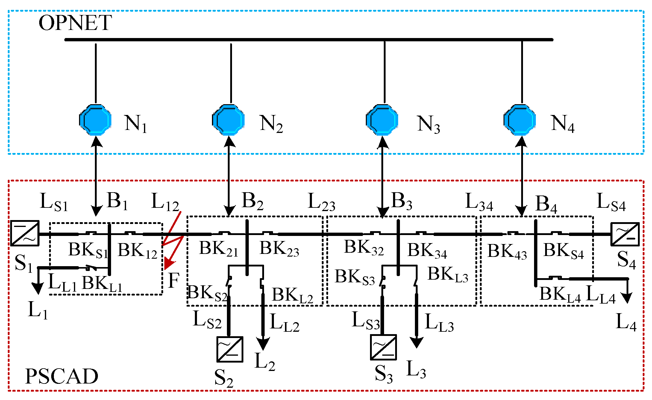
5.1. Co-Simulation Model

The structure of the co-simulation model is as shown in Figure 14. The power system part of the model is a shipboard low voltage AC distribution network powered by 4 inverters. In the system diagram, S1–S4 are inverters, L1–L4 are loads, B1–B4 are bus nodes. The information network part of the model is a CAN bus model based on ISO-11898 [28], in which nodes N1–N4 represent the corresponding controllers for bus nodes B1–B4 in the power system model. In the CAN bus network, the priority of nodes descends from N1 to N4. The modeling and simulation of CAN bus in OPNET is detailed in our previous work in [29].
In the co-simulation model, a communication-based protection strategy is implemented in the EMS on the basis of the characteristic current protection method proposed in [30]. The principle of system fault detection and protection based on characteristic current is as follows: When a short-circuit fault occurs in the system, the inverters switch their operation mode and output a characteristic current containing positive sequence fundamental current and current of 3-time rated frequency. After detecting the characteristic current, the breakers extracts its DC component through coordinate transformation and filtering, and identifies the amplitude and direction of the short-circuit current. Based on the short circuit current information and interlocking signals from neighboring breakers, each breaker can take protection actions accordingly.
Based on the protection principles, a communication-based protection strategy is proposed. In the proposed strategy, every node samples the current information of the corresponding breaker periodically. CAN bus node N1 is set as master node, while the other three nodes are slave nodes. The master node detects short-circuit faults in the system by monitoring the changing rate of bus current. When N1 detects the current changing rate exceeding the threshold, it means a short-circuit fault occurs in the power system. Then N1 will send data requests to slave nodes N2–N4. Upon receiving the data request, slave nodes send the information acquired form the breakers back to the master node. By analyzing local data and feedback data from all the slave nodes, the master node pinpoints the fault in the system, controls the local breaker, and broadcasts control command to all the slave nodes. When receiving the commands, the slave nodes control the breakers accordingly and clear the short-circuit fault together. The “event filter” in information network simulation is set according to breaker commands sent by all the nodes. If in the simulation event, one or more breaker status is changed, it means it is an interaction request and need to be processed as shown in Figure 11. Otherwise if all the breaker status stays the same, then the event is a common event and does not need processing. The parameters of the model are presented in Table 1.

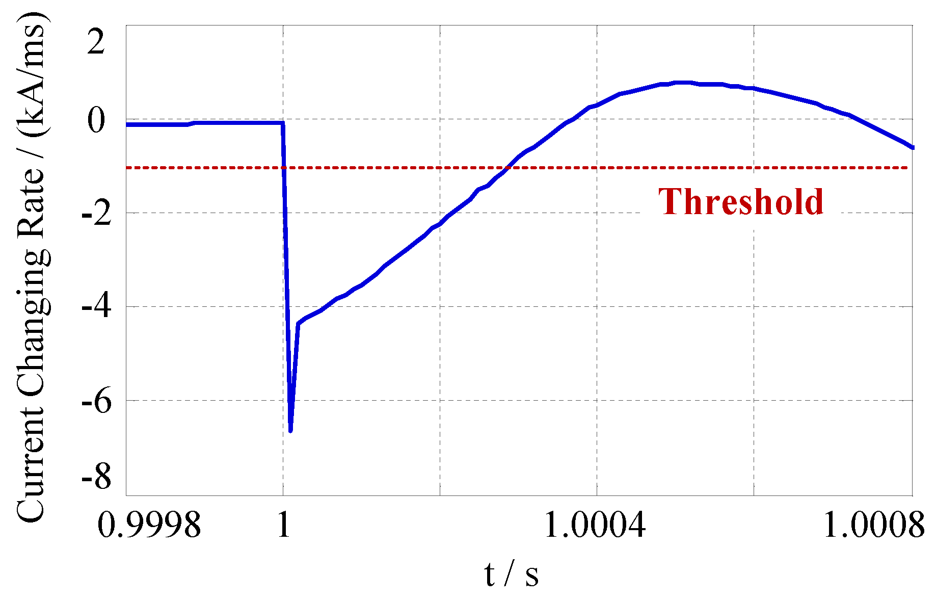
5.2. Co-Simulation Results

In the designed co-simulation case, a short-circuit fault occurs at transmission line L12 at 1s (shown as F in Figure 14). The communication-based protection process is analyzed with the proposed co-simulation method. The power system synchronization step is set as 500 μs. Figure 15 and Figure 16 show the current changing rate at breaker BKS1 and the characteristic currents detected by breakers BK21 and BK12 after the short-circuit fault occurs. According to the curves, after the short-circuit fault occurs, the current changing rate at breaker BKS1 immediately exceeds the threshold, and some of the breakers also detect the characteristic current exceeding the limit. Such data is transmitted into OPNET through the co-simulation synchronization process as input for the protection strategy. After the short-circuit fault, the data transmission delay between CAN bus nodes is shown in Figure 17 (the time in Figure 17 is relative to the short-circuit time).
As shown in Figure 17, the fault occurs at time 0, then it is detected by master node N1 after one power system synchronization step. At 500 μs, the master node broadcast data request to all slave nodes. Slave nodes N2–N4 receive the data request simultaneously after 336 μs and start to send feedback data immediately. As 3 nodes request to transmit data at the same time, conflict occurs in CAN bus and the arbitration process takes place. As a result, data from node N2, which has the highest priority, reaches N1 first, the delay is 311 μs. Data from the lowest-prioritized node N4 is received by N1 after 908 μs. The corresponding transmission delay range in similar conditions is usually 200–1000 μs, which is within the same range with the results [31,32,33]. After receiving and analyzing all the feedback data, N1 locates the fault at line L12 and send a break signal of BK12 to B1 through the HLA interface at 1744 μs, and also broadcast commands to all the salve nodes. After receiving the command, N2 send a break signal of BK21 to B2 through HLA at 2093 μs, N3 and N4 takes no action as they are not involved in the fault clearing process. Through the proposed optimized event-driven synchronization method, PASCD receives the commands at 1750 μs and 2100 μs (The PSCAD simulation step is set as 50 μs), and corresponding breakers clear the fault after inherent operation time, as shown in Figure 18 and Figure 19. The simulation results shows that through the proposed method, the co-simulation of communication-based power system protection can be implemented, and the effect of information network delay on power system performance can be demonstrated.
As comparison, the same co-simulation case is tested using the conventional fixed-step synchronization method and global even-driven method. In the fixed-step method, the synchronization step is also set as 500 μs. In the global even-driven method, the co-simulation is set to execute synchronization at each power system simulation step and also when an information network node send or receive a packet. The simulation time is set as 2 s. The comparison of co-simulation results and synchronization points involved are shown in Table 2 and Figure 20. In the aspect of precision, as the sampling step of power system is set as 500 μs, in all three simulations the master node detects the fault and send data request at the same time, which is at 500 μs. So, after the same controlling process, N1 and N2 also send commands at the same time, as shown in Table 2. In the global event-driven method and the proposed method, B1 and B2 receive break commands almost immediately after N1 and N2 send them via event detection. In the fixed-step method, B1 and B2 receive break command at 2000 μs and 2500 μs respectively, the action of breaker is significantly delayed due to the error introduced by the fixed-step synchronization process. It is evident that the proposed method and the event-driven method have a much higher precision than the fixed-step method. As for efficiency, the fixed-step method needs 4000 synchronization points in the process of co-simulation. The proposed method only needs 2 more synchronization points, which are transmitting the two breaker commands from OPNET to PSCAD. In the global even-driven method, the number of synchronization points is 40,008, as synchronizing at each power system simulation iteration alone takes 40,000 synchronization points. The number is much bigger than the fixed-step method and the proposed method. In conclusion, the proposed synchronization method can achieve a high precision and a relatively high efficiency at the same time.

6. Conclusions

In this paper, a cyber–physical co-simulation platform for shipboard CPPS research is built, then an optimized event-driven synchronization method is proposed based on the platform. The efficiency of the proposed method is further improved by simplifying the data transmission. Both the platform and the synchronization method are validated through co-simulation. The conclusions are as follows:
  • A cyber–physical co-simulation platform is established based on PSCAD and OPNET. Such a combination enables the platform to simultaneously simulate both power system and information network with high precision, which fits the requirements of shipboard CPPS research.
  • The platform is based on the HLA co-simulation framework. With the application of unified HLA interfaces in different simulators, the platform is highly expandable. It is convenient to incorporate other simulators in the platform and conduct more comprehensive co-simulation research of shipboard CPPS in the future.
  • In the co-simulation platform, both power system and information network simulation are incorporated in co-simulation by adding an independent component to the existing model, without any major modification to the existing model itself. Such a method is flexible and facilitates CPPS research based on existing shipboard power system models.
  • An optimized event-driven co-simulation synchronization method is proposed. By pre-defining power system interaction requests and detecting information network interaction requests in the simulation process, the proposed method can efficiently synchronize both simulations in time, thus greatly enhancing the co-simulation precision efficiently comparing to conventional methods.
  • The proposed method simplifies the data transmission in the synchronization from bidirectional to unidirectional. Thus, the data transmission load in co-simulation is cut in half and co-simulation efficiency is further improved.
A co-simulation model of small-scale shipboard AC distribution network short-circuit protection is built, and simulation validate both the platform and the synchronization method. In future works, the platform will be applied in the research of full-scale shipboard CPPS, with a complete power system model and a comprehensive information network model considering factors such as network malfunctions and background traffic. By incorporating more simulators, the platform can also be used to research the interplay between the energy generation, distribution, consumption and management processes. The platform will also be further refined in the process of future research.

Author Contributions

Conceptualization, Y.W., F.M. and L.F.; software, Y.W. and X.H.; validation, Y.W. and X.H.; investigation, Y.W. and F.M.; resources, L.F. and F.M.; writing—original draft preparation, Y.W.; writing—review and editing, L.F. and F.M.; supervision, L.F.; project administration, F.M.; funding acquisition, L.F. All authors have read and agreed to the published version of the manuscript.

Funding

This work was supported by National Basic Research Program of China (973 Program), grant number 613294; National Natural Science Foundation of China, grant number 51607185, 51877211; Project Foundation of Naval University of Engineering, grant number 425317Q104.

Conflicts of Interest

The authors declare no conflict of interest.

Abbreviations

AbbreviationDefinition
IPSShipboard Integrated Power System
EMSEnergy Management System
CPPSCyber–Physical Power System
HLAHigh Level Architecture
RTIRun Time Infrastructure
FSMFinite State Machine

References

  1. Nguyen, V.H.; Besanger, Y.; Tran, Q.T.; Nguyen, T.L. On Conceptual Structuration and Coupling Methods of Co-Simulation Frameworks in Cyber-Physical Energy System Validation. Energies 2017, 10, 1977. [Google Scholar] [CrossRef] [Green Version]
  2. Palensky, P.; van der Meer, A.; Lopez, C.; Joseph, A.; Pan, K. Applied Cosimulation of Intelligent Power Systems: Implementing Hybrid Simulators for Complex Power Systems. IEEE Indus. Elect. Mag. 2017, 11, 6–21. [Google Scholar] [CrossRef]
  3. Mueller, S.C.; Georg, H.; Nutaro, J.J.; Widl, E.; Deng, Y.; Palensky, P.; Awais, M.U.; Chenine, M.; Kuch, M.; Stifter, M.; et al. Interfacing power system and ICT simulators: Challenges, state-of-the-art, and case studies. IEEE Trans. Smart Grid 2018, 1, 14–24. [Google Scholar] [CrossRef]
  4. Baran, M.; Sreenath, R.; Mahajan, N.R. Extending EMTDC/PSCAD for simulating agent-based distributed applications. IEEE Power Eng. Rev. 2002, 22, 52–54. [Google Scholar] [CrossRef]
  5. Tong, X. The co-simulation extending for wide-area communication networks in power system. In Proceedings of the Asia-Pacific Power and Energy Engineering Conference, Chengdu, China, 28–31 March 2010; pp. 1–4. [Google Scholar]
  6. Nutaro, J.; Kuruganti, P.T.; Miller, L.; Mullen, S.; Shankar, M. Integrated hybrid-simulation of electric power and communications systems. In Proceedings of the 2007 IEEE Power Engineering Society General Meeting, Tampa, FL, USA, 24–28 June 2007; pp. 1–8. [Google Scholar]
  7. Lévesque, M.; Xu, D.Q.; Joós, G.; Maier, M. Communications and power distribution network co-simulation for multidisciplinary smart grid experimentations. In Proceedings of the The 45th Annual Simulation Symposium, Orlando, FL, USA, 26–30 March 2012; pp. 6–10. [Google Scholar]
  8. Yu, W.; Xue, Y.; Luo, J.; Ni, M.; Tong, H.; Huang, T. An UHV Grid Security and Stability Defense System: Considering the Risk of Power System Communication. IEEE Trans. Smart Grid 2016, 7, 491–500. [Google Scholar] [CrossRef]
  9. Awais, M.U.; Gawlik, W.; De-Cillia, G.; Palensky, P. Hybrid simulation using SAHISim framework. In Proceedings of the 8th International Conference on Simulation Tools and Techniques, Athens, Greece, 24–26 August 2015; pp. 273–278. [Google Scholar]
  10. Duan, Y.; Luo, L.; Li, Y.; Cao, Y.; Rehtanz, C.; Kuch, M. Co-simulation of distributed control system based on JADE for smart distribution networks with distributed generations. IET Gener. Trans. Distr. 2017, 11, 3097–3105. [Google Scholar] [CrossRef]
  11. Schütte, S.; Scherfke, S.; Tröschel, T. Mosaik: A framework for modular simulation of active components in smart grids. In Proceedings of the 2011 IEEE First International Workshop on Smart Grid Modeling and Simulation (SGMS), Brussels, Belgium, 17 October 2011; pp. 55–60. [Google Scholar]
  12. Li, W.; Monti, A.; Luo, M.; Dougal, R.A. VPNET: A co-simulation framework for analyzing communication channel effects on power system. In Proceedings of the 2011 Electric Ship Technologies Symposium, Alexandria, VA, USA, 10–13 April 2011; pp. 143–149. [Google Scholar]
  13. Li, W.; Luo, M.; Zhu, L.; Monti, A.; Ponci, F. A co-simulation method as an enabler for joint analysis and design of MAS-based electrical power protection and communication. Simulation 2013, 89, 790–809. [Google Scholar] [CrossRef]
  14. Li, W.; Zhang, X.; Dong, Y. Study of co-simulation methods applied in power systems (part I): VPNET. Proc. CSEE 2012, 32, I0013. [Google Scholar]
  15. IEEE Standard for Modeling and Simulation (M&S) High Level Architecture (HLA)—Framework and Rules; IEEE Std.: Piscataway, NJ, USA, 2000; pp. 1516–2000.
  16. Roth, T.; Burns, M. A gateway to easily integrate simulation platforms for co-simulation of cyber-physical systems. In Proceedings of the workshop on Modeling and Simulation of Cyber-Physical Energy Systems, Porto, Portugal, 10 April 2018; pp. 1–6. [Google Scholar]
  17. Hopkinson, K.; Wang, X.; Giovanini, R.; Thorp, J.; Birman, K.; Coury, D. EPOCHS: A platform for agent-based electric power and communication simulation built from commercial off-the-shelf components. IEEE Trans. Power Syst. 2006, 21, 548–558. [Google Scholar] [CrossRef]
  18. Hopkinson, K.; Birman, K.P.; Giovanini, R.; Anini, R.G.; Coury, D.; Wang, X.; Thorp, J. EPOCHS: Integrated commercial off-the-shelf software for agent-based electric power and communication simulation. In Proceedings of the Winter Simulation Conference, Piscataway, NJ, USA, 7–10 December 2003; pp. 1158–1166. [Google Scholar]
  19. Georg, H.; Muller, S.C.; Dorsch, N.; Rehtanz, C.; Wietfeld, C. INSPIRE: Integrated co-simulation of power and ICT systems for real-time evaluation. In Proceedings of the 2013 IEEE International Conference on Smart Grid Communications, Vancouver, BC, Canada, 21–24 October 2013; pp. 576–581. [Google Scholar]
  20. Georg, H.; Wietfeld, C.; Müller, S.C.; Rehtanz, C. A HLA based simulator architecture for co-simulating ICT based power system control and protection systems. In Proceedings of the IEEE Third International Conference on Smart Grid Communications, Tainan, Taiwan, 5–8 November 2013; pp. 264–269. [Google Scholar]
  21. Georg, H.; Müller, S.C.; Rehtanz, C.; Wietfeld, C. Analyzing cyber-physical energy systems: The INSPIRE cosimulation of power and ICT systems using HLA. IEEE Trans. Indus. Infor. 2014, 10, 2364–2373. [Google Scholar] [CrossRef]
  22. Yin, Q.; Duan, B.; Kang, C.; Li, H. Joint simulation design of energy system and information communication system based on HLA/Agent. Autom. Electr. Power Syst. 2016, 40, 22–29. [Google Scholar]
  23. Chen, G.; Zhang, Z.; Yin, X. Design of wide-area backup protection simulation platform based on HLA/Agent. Proce. CSEE 2013, 33, 153–162. [Google Scholar]
  24. Shum, C.; Lau, W.H.; Mao, T.; Chung, H.S.; Tsang, K.; Tse, N.C.; Lai, L.L. Co-Simulation of Distributed Smart Grid Software Using Direct-Execution Simulation. IEEE Access 2018, 6, 20531–20544. [Google Scholar] [CrossRef]
  25. Lin, H.; Veda, S.S.; Shukla, S.S.; Mili, L.; Thorp, J. GECO: Global Event-Driven Co-Simulation Framework for Interconnected Power System and Communication Network. IEEE Trans. Smart Grid 2012, 3, 1444–1456. [Google Scholar] [CrossRef]
  26. Brito, A.V.; Bucher, H.; Oliveira, H.; Costa, L.F.S.; Sander, O.; Melcher, E.U.K.; Becker, J. A Distributed Simulation Platform Using HLA for Complex Embedded Systems Design. In Proceedings of the 2015 IEEE/ACM 19th International Symposium on Distributed Simulation and Real Time Applications (DS-RT), Chengdu, China, 14–16 October 2015; pp. 195–202. [Google Scholar]
  27. Lu, D.Z.; Yang, H. Unlocking the Power of OPNET Modeler; Cambridge University Press: Cambridge, UK, 2012. [Google Scholar]
  28. ISO 11898-1. Road Vehicles—Controller Area Network (CAN)-Part 1: Data Link Layer and Physical Signaling; International Standard Organization: Geneva, Switzerland, 2003. [Google Scholar]
  29. Wu, Y.; Fu, L.; Xu, Y.; Ma, F.; Lu, Y. Controller area network modeling and its application in cyber-physical power system co-simulation. In Proceedings of the 37th Chinese Control Conference, Wuhan, China, 25–27 July 2018; pp. 6178–6183. [Google Scholar]
  30. Hao, X.; Ma, F.; Ren, Q. Directional interlocking overcurrent protection of microgrids powered by inverters injected with characteristic currents. In Proceedings of the 43rd Annual Conference of the IEEE Industrial Electronics Society (IECON), Beijing, China, 29 October–1 November 2017; pp. 220–226. [Google Scholar]
  31. Ni, X.; Zhang, Y. Determining message delivery delay of controller area networks. In Proceedings of the 2002 IEEE Region 10 Conference on Computers, Communications, Control and Power Engineering, Beijing, China, 28–31 October 2002; pp. 767–771. [Google Scholar]
  32. Luo, G.; Dong, K.; Feng, N.; Li, K.; Lian, X. CAN modeling and simulation of a hybrid electric vehicle based on OPNET. Jour. Tsing. Univ. 2005, 5, 689–692. [Google Scholar]
  33. Li, X.; Ding, F.; Xiong, H. CAN Modeling and simulation based on OPNET. Jour. Beijing Univ. Aero. Astro. 2009, 35, 284–288. [Google Scholar]
Figure 1. Typical co-simulation platform based on high level architecture (HLA) and run time infrastructure (RTI).
Electronics 09 00540 g001
Figure 2. Structure of cyber–physical co-simulation system.
Electronics 09 00540 g002
Figure 3. Events in power system and information network simulations.
Electronics 09 00540 g003
Figure 4. Conventional fixed-step synchronization.
Electronics 09 00540 g004
Figure 5. Conventional global event-driven synchronization.
Electronics 09 00540 g005
Figure 6. Optimized event-driven synchronization method.
Electronics 09 00540 g006
Figure 7. Synchronization process of the co-simulation platform.
Electronics 09 00540 g007
Figure 8. Bi-directional data exchange in co-simulation.
Electronics 09 00540 g008
Figure 9. Optimized unidirectional data exchange in co-simulation synchronization.
Electronics 09 00540 g009
Figure 10. Data exchange between OPNET model and RTI based on HLA node.
Electronics 09 00540 g010
Figure 11. OPNET process model which implements data exchange with RTI.
Electronics 09 00540 g011
Figure 12. PSCAD interface based on user-defined module and socket.
Electronics 09 00540 g012
Figure 13. Operation process of PSCAD user-defined module.
Electronics 09 00540 g013
Figure 14. Co-Simulation model of communication-based protection.
Electronics 09 00540 g014
Figure 15. Current changing rate at breaker BKS1.
Electronics 09 00540 g015
Figure 16. Characteristic currents at breakers BK21 and BK12.
Electronics 09 00540 g016
Figure 17. Time delay of data transmission.
Electronics 09 00540 g017
Figure 18. Short-circuit and breaker signals in co-simulation.
Electronics 09 00540 g018
Figure 19. Three-phase current at BK12.
Electronics 09 00540 g019
Figure 20. Comparison of BK12 three-phase current in the proposed synchronization method and the conventional fixed-step method.
Electronics 09 00540 g020
Table 1. Parameters of co-simulation model.
ParameterValue
Rated capacity of inverter562 kVA
Rated output voltage of inverter400 V
Rated output current of inverter811.9 A
Amplitude of characteristic current162.4 A
Length of transmission lines50 m
Threshold of short-circuit current changing rate±1000 A/ms
Threshold of short-circuit current direction judge229.6 A
Step of sampling500 μs
Bandwidth of CAN bus500 kbps
Length of a standard CAN bus packet108 bit
Table 2. Result comparison of the proposed synchronization method and the fixed-step method.
MethodN1 Sending
Command
B1 Receiving CommandN2 Sending
Command
B2 Receiving CommandNumber of
Synchronization Points
Fixed-step Method1744 μs2000 μs2093 μs2500 μs4000
Global Event-Driven Method1744 μs1750 μs2093 μs2100 μs40,008
Proposed Method1744 μs1750 μs2093 μs2100 μs4002

