Article

Monopulse Antenna Based on Singular Spoof Surface Plasmon Polariton Structure for Angle Measurement

1
State Key Laboratory of Millimeter Waves, Southeast University, Nanjing 210096, China
2
College of Telecommunications and Information Engineering, Nanjing University of Posts and Telecommunications, Nanjing 210003, China
*
Author to whom correspondence should be addressed.
Electronics 2020, 9(12), 2156; https://doi.org/10.3390/electronics9122156
Submission received: 6 November 2020 / Revised: 8 December 2020 / Accepted: 14 December 2020 / Published: 16 December 2020
(This article belongs to the Special Issue Evolutionary Antenna Optimization)

Abstract

:
Direction finding and target tracking make demanding requirements on the measurement of incoming angles of electromagnetic waves. A monopulse antenna, based on the singular symmetric spoof surface plasmon polariton (SSPP) structure, is proposed for high-accuracy angle sensing. The singular SSPP structure is composed of periodic corrugated grooves for the confinement of the electromagnetic fields. Due to the microstrip–coplanar waveguide transition, the fields along both sides of the SSPP add constructively to form the endfire beam at the sum port and destructively to form the null radiation in the endfire direction at the difference port. An optimization based on the team progress algorithm is adopted to facilitate this antenna design. A prototype is designed and fabricated to validate the design principle, and measured results agree with the simulation. The proposed antenna shows a wide bandwidth ranging from 5.0 GHz to 7.5 GHz for both the sum and difference ports with the return loss greater than 10 dB, realizing a relative bandwidth of 40%. The isolation for the sum and difference ports is higher than 21 dB, and the null depth is larger than 20 dB over the entire operating range, which is favorable for the high accuracy angle sensing and measurement. This monopulse antenna has broad prospect in angle measuring systems such as direction finding and radar tracking scenes.

1. Introduction

Along with the frequency, amplitude, phase, and the polarization, the propagating direction is a basic factor of the electromagnetic wave. For the communication applications, the electromagnetic wave is radiated and sent to the specified directions to realize the information interchange. This leads to the different types of radiation patterns of the antennas, namely omni-directional pattern, directional pattern, and so forth. Moreover, it provides rich information when applying in the radar systems. The antennas may obtain the distance of the detected object [1,2], the direction to the objects [3], and velocity of the objects [4,5] by analyzing parameters of the echo signals [6], where information is attached with the change of propagation properties of the radio waves [7].
Consequently, for providing the target angle information, one task for the radar systems is to measure the propagating direction of the electromagnetic waves. Direction finding antennas and systems and tracking radars have been designed for radio navigation and satellite positioning, based on conical-scanning antennas and the sequential lobing method [8]. The lag error, due to the necessary time period of the detecting cycle, may cause error in the measured tracking angle, and simultaneous detection is required for high detecting precision [9]. Monopulse antenna is another scheme, providing simultaneous lobe comparison and the technique in direction measuring of radiation from reflected signals.
Monopulse antennas configurations have been widely designed with array and multi-aperture schemes [10,11,12,13,14,15,16,17], which provide high gain of sum beam and deep radiating null in the detecting direction. Meanwhile, a feeding network with high complexity is required with the increase of element number [18,19,20]. Antennas with a single aperture [21,22] and simple feeding network, which has the potential for array application scenarios and reducing the complexity of designing the feeding network, requires further investigation.
Optimization of the reflection coefficient is of great significance for the proposed antenna because quantities of variables have the influence on the reflection coefficient, including the dimensions of the feeding structure and the SSPP radiating structure. Many optimization methods have been widely adopted in antenna and microwave component designing scenarios, including electromagnetic band-gap [23], spatial phase shifters [24], frequency selective surface, and array synthesis [25,26,27]. Among the algorithms, the team progress algorithm (TPA) is suitable for the optimization of the proposed antenna, which is an intelligent optimization algorithm that simulates a team upgrading process with member learning, exploring, and renewal, and it has the abilities of global, local, and directional search [28].
In this work, a monopulse antenna is designed with the singular symmetric spoof surface plasmon polariton (SSPP) structure. The singular SSPP structure is composed of periodic corrugated grooves, which confines the electromagnetic field near the metal and dielectric interface. At the microstrip line and the coplanar waveguide, the field along both sides of the SSPP add constructively to form the endfire beam at the sum port and destructively to form the null radiation in the endfire direction at the difference port. A prototype is designed and optimized to validate the proposed design principle, and the measured results agree with the simulation. In the frequency range from 5.0 GHz to 7.5 GHz, the proposed antenna shows a return loss greater than 10 dB for both the sum and difference ports, realizing a relative bandwidth of 40%. The isolation for the sum and difference ports is higher than 21 dB, and the null depth is larger than 20 dB over the entire operating range. Consequently, the monopulse antenna is favorable for the high accuracy angle sensing and measurement, and it shows broad prospect in direction finding and radar tracking scenes.
The remainder of the paper is organized as follows. Section 2 presents the antenna structure and the design principle of the proposed antenna, including the sum and difference feeding network, the optimization procedure, the radiation performance, and the mode isolation of the SSPP. The simulated and measured results are presented and discussed in Section 3. A brief conclusion is presented in Section 4.

2. Analysis and Design

The structure of the proposed monopulse antenna and the design principle would be described in this section. The operating mechanism of the sum and difference feeding network is also be included in this section.

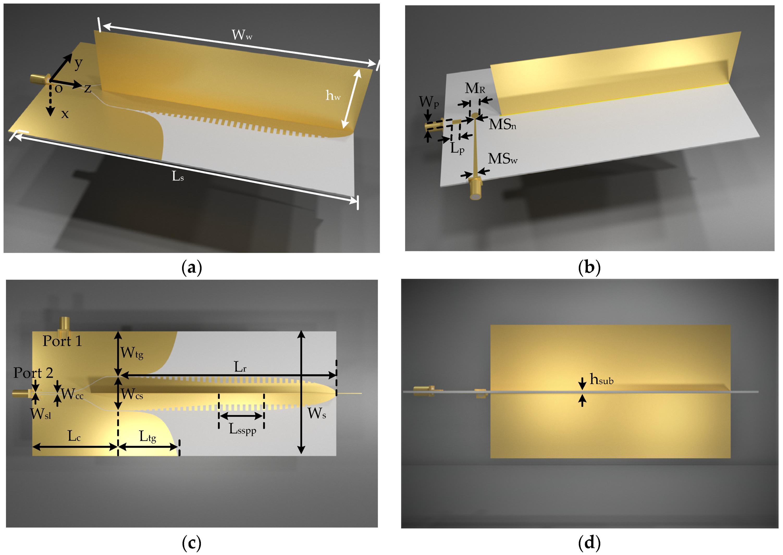
2.1. Antenna Configuration

The configuration of the proposed monopulse antenna is depicted in Figure 1. For showing the detailed structure, the front side view, back side view, top view, and the side view are provided. The monopulse antenna is composed of an SSPP transmission line fed by a coplanar waveguide port and a microstrip line port. The SSPP, with corrugated grooves along both sides, supports the slow wave mode and confines the energy near its metal and dielectric interface. A gradually narrowing termination is adopted at the end of the SSPP structure for matching with the free space and releasing the confined energy to the space. A metal plate is installed in the middle of the SSPP structure, and thus, the interrelation between the SSPP modes along both sides would be diminished.
A coplanar waveguide port and a microstrip line port are utilized for feeding the proposed monopulse antenna. At the microstrip line port, the electromagnetic fields propagating along the SSPP structure add constructively and form an endfire radiation pattern. On the contrary, at the coplanar waveguide port, the electromagnetic fields would add destructively and lead to a difference beam with a null in the endfire direction. Therefore, a monopulse antenna with simultaneous sum and difference beams would be realized, corresponding to the microstrip line port and the coplanar waveguide port, respectively.

2.2. Field Confinement of the Spoof Surface Plasmon Polariton

The SSPP mode is an electromagnetic field distribution along the interface of metal and dielectric mediums. The phase velocity for the SSPP mode is slower than that for the light propagating in the vacuum. Due to the structure along the interface, the field is confined closely near to it and transmits along the SSPP. The corrugated grooves, with different periods, depths, and gap widths, could be utilized for enhancing the field confinement. Meanwhile, due to this field confinement, the effective permittivity of this SSPP transmission line is altered and varies with the operating frequency. For the high frequency, due to the increased energy proportion in the substrate, the effective permittivity adds nonlinearly with the frequency. This also leads to the decrease of the propagation velocity, which can be inferred from the dispersion curves shown in Figure 2. The dispersion curves are obtained in the CST Microwave studio by using the eigenmode solver. For the periodic grooves with greater depth, the dispersion effect becomes obvious, and the cutoff frequency decreases quickly. The change of the cutoff frequency, resulting from the corrugated grooves, limits the operating frequency range for the proposed monopulse antenna.

2.3. Sum and Differential Feeding Network

Since the field confinement of the SSPP split the center conductor into two separated SSPP transmission lines, the antenna is considered as a two-element array and fed by two slotlines of the feeding network, which is known as the sum and difference (or monopulse) network. The sum or difference radiating pattern of the proposed monopulse antenna is established in the far-field region when the field on the two sides of the symmetric SSPP structure is in the same or symmetric distribution. The sum and difference feeding network is composed of a coplanar waveguide (CPW) on the top layer and a microstrip line on the bottom layer. The microstrip line is coupled with the CPW. When the input port is the microstrip line, the coupled slotlines of the CPW with odd mode field distribution are provided. The same field distribution produces a couple of in-phase signals in the slotlines and feeds the two-element array. Meanwhile, the CPW port is isolated from odd mode signals due to the connecting bridge over the ground planes of different potential. Similarly, when the input is at the CPW port, even mode field distribution is established in the CPW, and the microstrip line is isolated from the even mode signals. In the even mode, symmetric field distribution forms the equivalent out-of-phase signals and feeds the symmetric SSPP structure, and destructive addition of the field is formed at the terminal of the center conductor.

2.4. Design and Optimization Using Team Progress Algorithm

The team progress algorithm (TPA) [28,29] is utilized for the design and optimization of the proposed antenna. The optimization procedure based on the TPA is shown in Figure 3. For optimization, the software depicted in Figure 4 is implemented, and the full-wave simulation is realized by incorporating with the CST microwave studio (MWS). The optimization settings, such as the parameters, the objective functions, and the classifications of the performance, are preset in the main program. The parameters are predicted based on the team progress algorithm and are updated to the CST MWS. The scattering parameters are calculated by the time domain solver of CST MWS. After calculating in the CST MWS, the results are returned to the main program. Then, the evaluation and comparison of the performance, the classification of the samples, and the decision making are performed in the main program.
For the proposed antenna, the field distribution and the radiated sum and difference beams are basically determined by the SSPP and the feeding modes, which have been described in Section 2.2 and Section 2.3 and can be designed theoretically. The port matching performance is optimized by the TPA, and the convergence result for the sum port is shown in Figure 4. In this optimization, the maximum iteration number is set as 140, including 40 team members served in the elitist group and the plain group. According to the result in Figure 4, the optimization procedure converges quickly after the initialization of the elitist group and the plain group. TPA is a global optimization algorithm, and it could search the optimum in the entire space. With the increase of the iteration, the percentage of “good” performance increases constantly. Meanwhile, the TPA keeps searching in the entire space, trying to avoid the local optimum. This leads to the scattered samples in the iteration optimization procedure, as shown in Figure 4. A maximum reflection coefficient of −10.68 dB in the frequency range from 5.0 GHz to 7.5 GHz is obtained at the 133rd calculation.

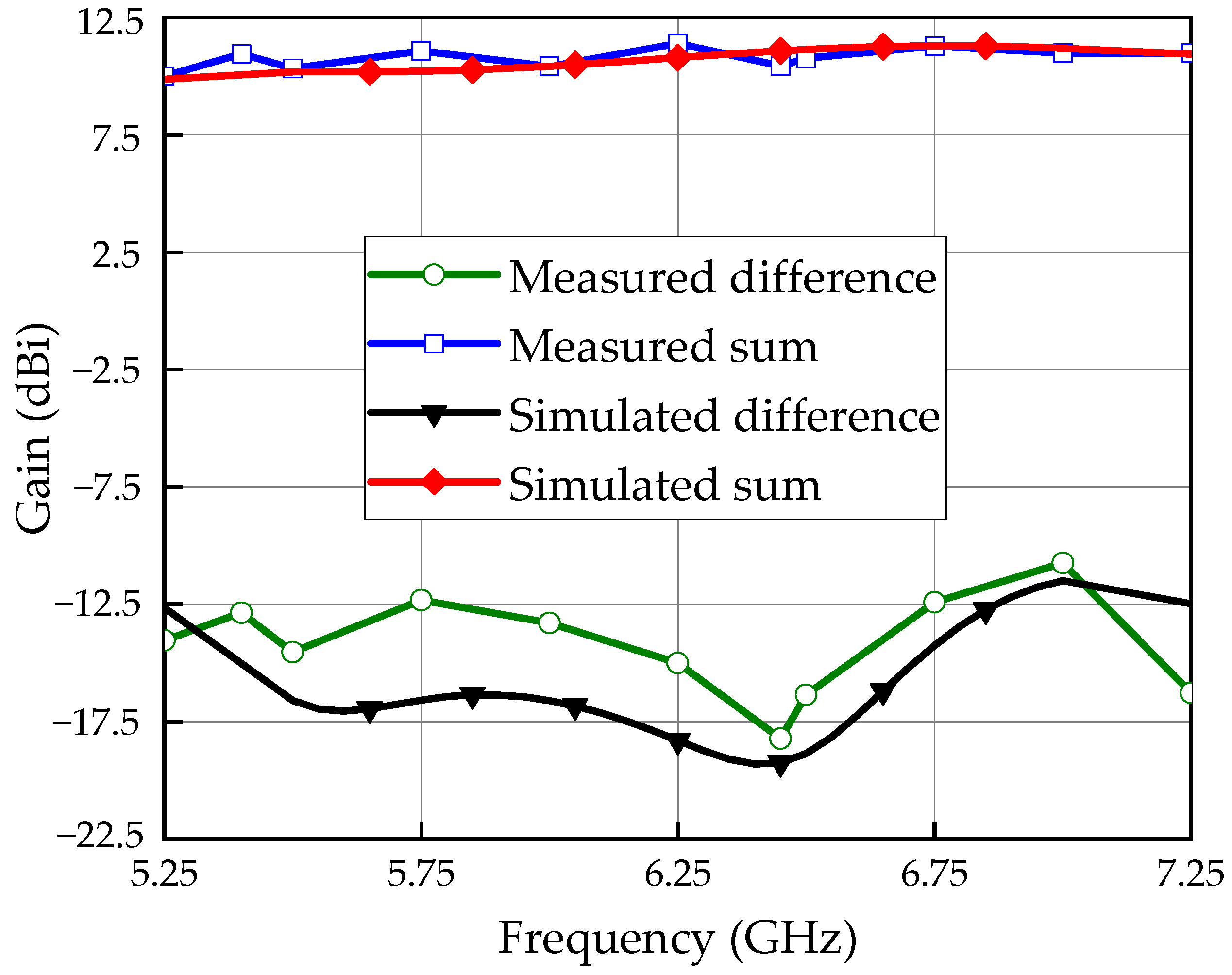
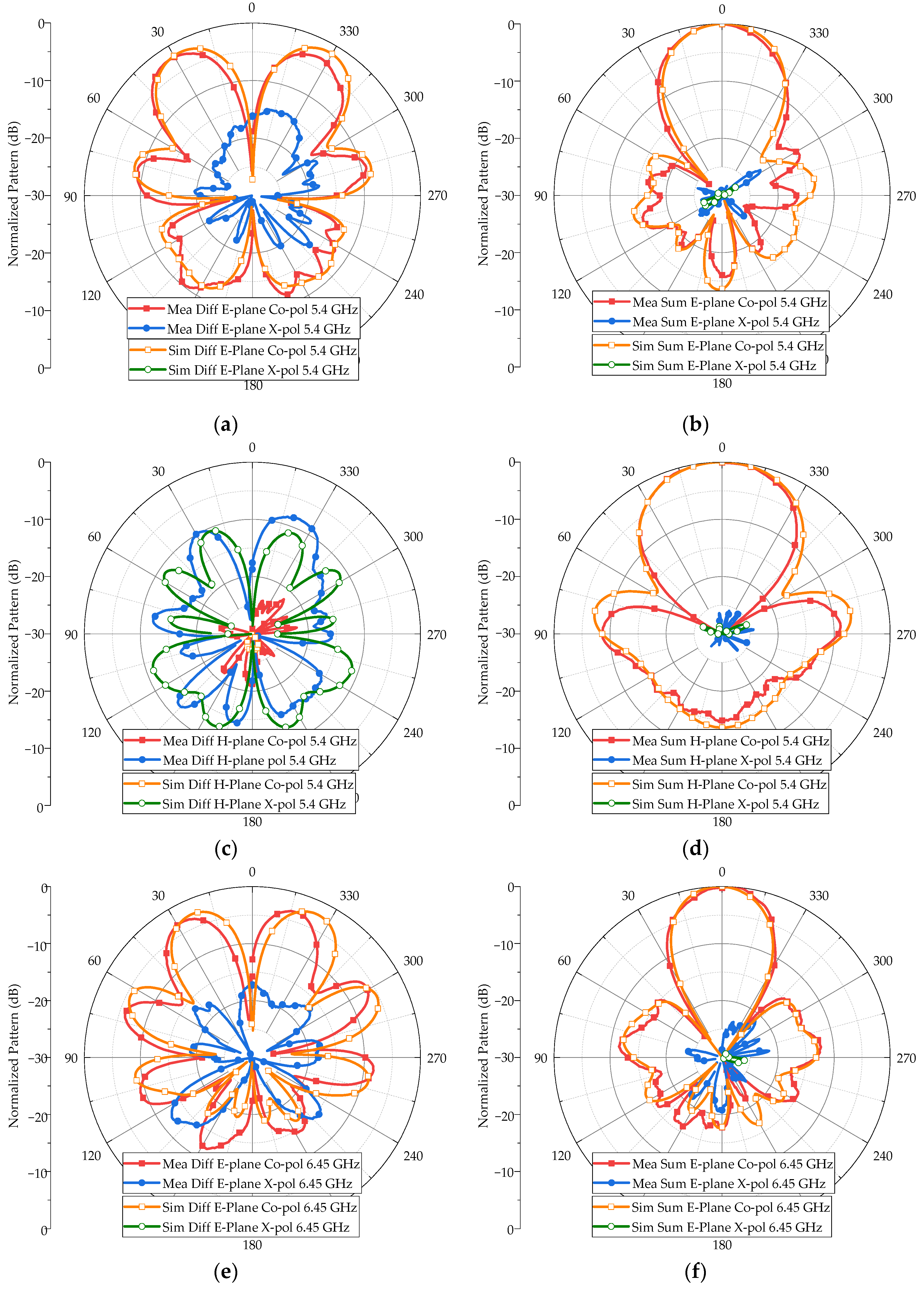
2.5. Monopulse Radiation Performance

According to the analysis above, the sum and difference beam is achieved by different feeding modes. The signal fed by the sum beam port 1 is transmitted to the corrugated section by the feeding network with the equal magnitude and in-phase fields. The magnitude of the transverse field distribution for the sum beam is presented in Figure 5a. The field distribution and radiation patterns are obtained with the time domain solver of CST MWS. The gradient grooves and flaring are favorable for transforming the slotline mode to the SSPP mode. When the signals of two sides of SSPP reach the antenna terminal through the SSPP and then gradually radiate to the free space, the sum beam pattern is obtained due to the in-phase superstition of far-field electric fields; meanwhile, the signal fed by the difference port 2 is divided at the two sides of SSPP with the equal magnitude and out-of-phase electric fields. Figure 5b shows the magnitude of transverse field distribution of the difference beam. It can be seen that the signals on the two sides are out-of-phase both for the transmission and radiation states. As a result, the difference beam pattern is obtained in the far field. Meanwhile, the central metal plate can efficiently isolate the interference of electric fields with different phase velocity in the transmission region and ensure that the energy on the both sides are transmitted to the end of the SSPP without an additional phase shift.
The corrugated groove length has a major effect on the endfire directivity of the antenna since the SSPP section cannot absolutely confine the electromagnetic energy on the interface of the metal and dielectric substrate. The endfire directivity of the sum beam for different lengths of corrugated groove section varying with frequency is plotted in Figure 6. A shorter length corresponds to a relatively lower directivity, while a longer length means a higher directivity but with a narrower band of constant directivity. The length of 100 mm is a compromise between high directivity and a wide band.

2.6. Directivity in the Endfire Direction

The variation of directivity reflects the significance of dimension design for the antenna. The directivity of the antenna is influenced by the phase distribution on the aperture of the antenna. The phase distribution depends mainly on the phase difference between the power propagating on the SSPP structure and the power leaked into free space by the slot–SSPP transition structure. The field is confined in a closer range to the conductor of the SSPP, and at the terminal section, electromagnetic field is released. Meanwhile, the field leaked by the slot–SSPP transition structure is at a distance from the conductor, as is shown in Figure 5. As is depicted in Figure 2, the phase constant of the SSPP increases rapidly with the growth of frequency, while the phase constant of waves propagating in the free space is a constant. According to [30], nonuniform phase distribution will result in a directivity drop due to the field addition that is formed in the far-field region:
D ( d B ) = 20 l g [ A c o s ( Δ k ( f ) n l ) + 1 ] 10 l g [ P r a d / C 2 ]
where Δk(f) is the difference of phase constant, n is the unit cell number of the SSPP structure, l is the length of the SSPP unit cell, Prad is the radiated power, and C is a frequency-independent constant. This equation demonstrates the relation between directivity D and phase difference Δk(f)∙n∙l. With the length change of the SSPP, the phase difference increases, resulting in nonuniform phase distribution on the aperture. Consequently, destructive addition is formed and the directivity of the sum beam drops at the frequency where the phase difference between the radiated fields is 180 degrees. The directivity variation corresponding to frequency is depicted in Figure 6.
Dimensions of the corrugated edge of the center conductor also requires attention in design. As is shown in Figure 2, dispersion curves of unit cells with different dimensions are various, and, according to (1), the phase constant k increases with the growth of depth of the corrugations. The directivity variation versus groove depth d is plotted in Figure 7, demonstrating that the frequency of directivity drop reduces with the growth of frequency, while in the operating band, the directivity is enhanced up to 1 dB when d increases. Therefore, the directivity reaches a minimum when the total phase difference is at 180°. As is depicted in Figure 8, the electric field near the SSPP and in free space forms a phase difference of 180° at the aperture of at 10 GHz, where the directivity of the antenna with a 4 mm groove depth reaches its minimum. To avoid the directivity drop due to the dispersion and enhance the directivity of sum beams provided by the field confinement in operating frequency, the dimensions are expected to be particularly designed.

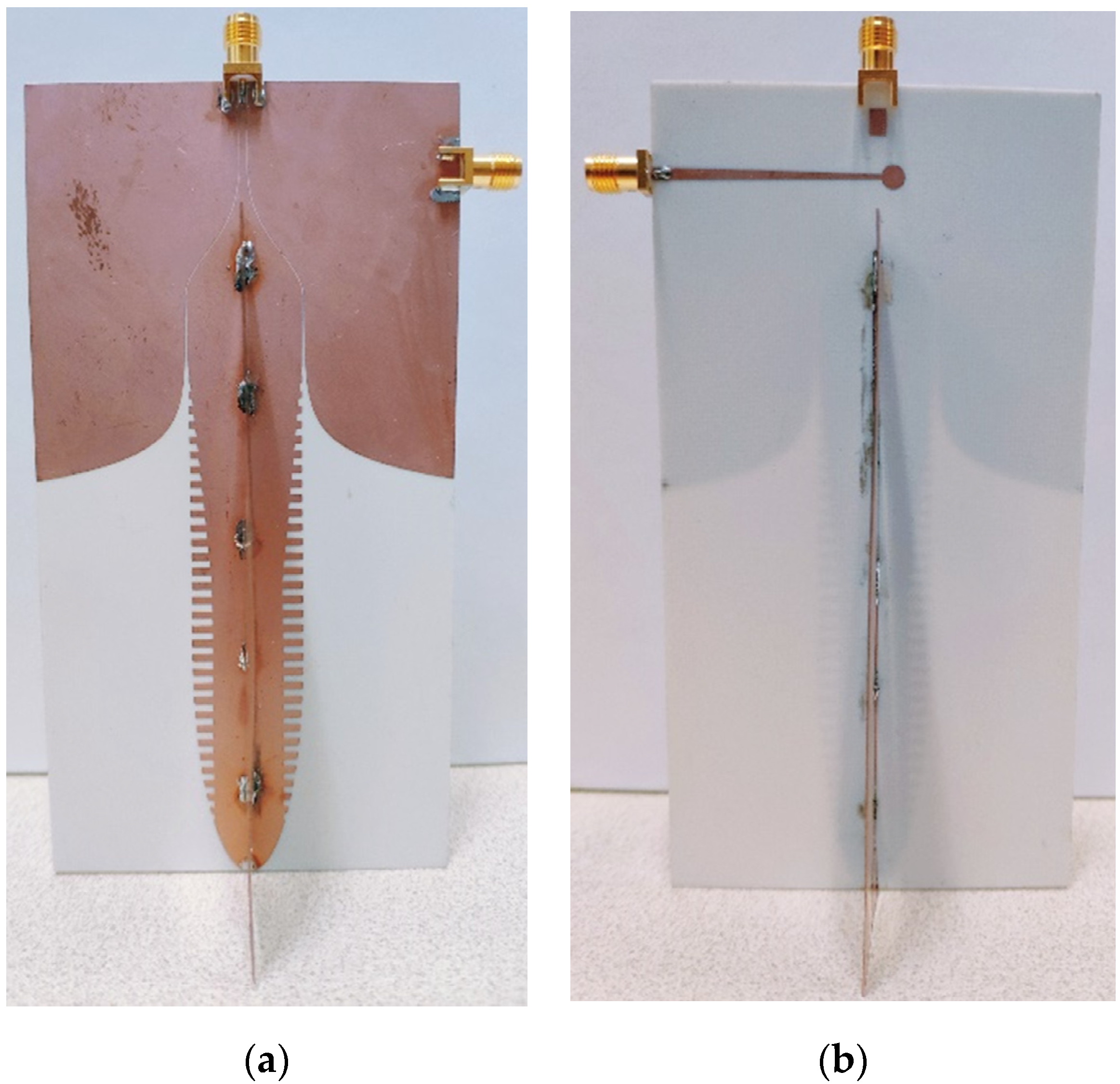
3. Fabrication and Results

3.1. Fabrication

The proposed antenna is fabricated with Rogers RO4003C, whose relative permittivity is 3.55 at 10 GHz and thickness is 0.813 mm. Two copper metal plates are adopted and soldered in the middle of the singular SSPP structure to enhance the isolation of the SSPP modes on both sides. The dimensions of the antenna configuration are shown in Table 1, and the fabricated antenna is demonstrated in Figure 9.

3.2. Scattering Parameters

The scattering parameters for the proposed monopulse antenna is measured with an Agilent vector network analyzer (VNA) N5230A. The simulated and measured results show acceptable agreement, as is depicted in Figure 10. The measured reflection coefficient is below −10 dB in the frequency range from 5.0 GHz to 7.5 GHz for both the sum and difference ports, showing good matching operating states. This realized bandwidth corresponds to a relative bandwidth of 40%, and it makes the proposed antenna applicable for wide band angle measurement systems. Meanwhile, the isolation for the sum and difference ports is higher than 21 dB in the entire operating frequency range. Consequently, the interference between the sum beam and the difference beam is minimized. The handmade copper plate and manual installation accounts for the performance discrepancy between the simulated and measured results. An isolation wall based on both sides of the copper covered printed circuit board and fixing holes could alleviate this discrepancy.

3.3. Radiation Performance

Radiation performance, including gain and radiation patterns of the proposed monopulse antenna, is measured in the anechoic chamber, and the measurement installation of this antenna is shown in Figure 11. One port is terminated with a matching load when the beam corresponding to another port is measured.
Gain of the antenna in the endfire direction is measured, and the results of the measured gain are demonstrated in Figure 12 along with the simulated ones. The measured results show the same trend of gain variation with the growth of frequency, which is also in good agreement with the simulated results. For the gain corresponding to the sum beam port, it shows a flat curve of about 10 dBi with a fluctuation less than 1 dB. In contrast to the sum beam, the gain for the difference beam port is lower than −11 dB in the frequency range from 5.25 GHz to 7.25 GHz. Consequently, a sum–difference ratio of 20 dB is obtained for the proposed monopulse antenna in the entire wide bandwidth.
Radiation patterns of the proposed antenna are measured in the anechoic chamber. Measured and simulated patterns, including both the sum and difference beams, are depicted in Figure 13, according to which the measurement agrees well with the simulation.
The radiation patterns at the 5.4 GHz, 6.45 GHz, and the 6.7 GHz are measured and compared with the simulated ones. The beams associated to the sum port show a maximum radiation in the endfire direction, having a front–back ratio of about 15 dB. The measured sum beam demonstrates a side lobe level of about −10 dB, and this may be further suppressed with the array factor in array designs. For the beams corresponding to the difference port, it can be inferred that the null is constantly in the endfire direction, and a stable null angle is important for the direction measurement and specification. The measured null depth at these three frequency points is all below −20 dB, which coincides with the measured sum and difference gain shown in Figure 13. Thus, the stable null direction and the large null depth facilitate the measurement of the incoming wave angle with high accuracy.
The difference beam of the proposed monopulse is characterized using the phase and magnitude difference over the operating band. The measurement setup is shown in Figure 14. Two antennas are installed with a distance of 1.0 m in the transmitting–receiving mode. The vector network analyzer is utilized for measuring the transmission coefficient between the two antennas. For the transmitting antenna, the sum port is excited, while the difference port is terminated with a match load. The difference port of the receiving antenna is connected to the VNA, and the sum port is matched to a 50-ohm load. For reducing the interference for the secondary reflection, absorbers are placed between the transmission path of the two antennas.
It is worth noting that the received signal at the sum port and the difference port originates from one and the same reflected signal. For the reflected signals from the targets appeared symmetrically on both sides of the boresight directions, they incident on the monopulse antenna in +θ and −θ directions, as shown in Figure 15. The corresponding difference signals can be expressed as follows
D+θ(t) = sin(wt + φ) − sin(wt + φ + n) = 2 sin(n/2)cos(wt + φ + π + n/2)
Dθ(t) = sin(wt + ψ + m) − sin(wt + ψ) = 2 sin(m/2)cos(wt + ψ + m/2).
For the target with the same distance and the same scattering performance, the propagating phase delay in +θ and −θ directions is the same, and we have
φ = ψ.
Due to the symmetrical configuration of the monopulse antenna, the phase difference between the two antenna elements is the same, and we have
n = m.
Consequently, according to (2)–(5), the difference signals in +θ and −θ directions for the same targets satisfy the relation shown as follows
D+θ(t) = −Dθ(t).
For the sinusoidal signal, (6) implies that the two difference signals have the same magnitude and the reversed phases. This is the principle for the measurement shown in Figure 15.
The transmitting–receiving mode measured results are shown in Figure 16. The transmission coefficient for the endfire direction along with these for the ±3° directions are measured, and their phase and magnitude are provided. According to Figure 16a,b, the phase difference between the −3° and the endfire directions is positive, while it is negative between the +3° and the endfire directions. The opposite sign provides the tracking direction for the angle measurement systems. The magnitude difference, between the ±3° directions and the endfire direction, is above 5 dB in most frequency points. Therefore, the phase and magnitude difference show clearly the performance of the difference beam and its ability for angle measurement. The measured results validate the analysis and the result shown by (6). The difference beam has high angle accuracy, and just for this reason, the measurement of difference beam performance put demanding requirements for the antenna installation. Therefore, the results for the transmitting–receiving mode measurement are a qualitative validation for the difference beam performance. Along with the results measured in the anechoic chamber, the angle measurement performance of this monopulse antenna could be characterized comprehensively.
A comparison, between the proposed monopulse antenna and the reference antennas, is shown in Table 2. As can be seen, the antenna of this work has the widest bandwidth the same as [13] with a single SSPP structure. This antenna is favorable for the flush mounted scene due to the endfire radiation patterns.

4. Conclusions

In this work, a monopulse antenna based on the singular SSPP structure is designed, and the principle of realizing the sum and difference beams is analyzed and validated. Superposition of the radiated electromagnetic fields of the in-phase and out-of-phase cases, provided by the singular SSPP, leads to the simultaneous sum and difference endfire beams. A prototype of the antenna is designed, fabricated, and measured in the frequency band from 5.0 GHz to 7.5 GHz, showing a relative bandwidth of 40%. The isolation for the sum and difference ports is greater than 21 dB, and the null depth is larger than 20 dB over the entire operating range, facilitating the high accuracy angle sensing and measurement. This monopulse antenna can be used for angle measuring systems such as direction finding and radar tracking scenes.
The bandwidth and the installation process could be further improved. The proposed monopulse antenna realizes a relative bandwidth of 40%, and the angular sensing and tracking functions could be enhanced with a larger bandwidth. On the other hand, the installation of this antenna is somewhat complex and inaccuracy, leading to the performance deterioration. An isolation wall based on the printed circuit board and fixing holes could be a solution for this problem.

Author Contributions

Conceptualization, S.L.; Data curation, J.L.; Formal analysis, H.Z. and X.Y.; Funding acquisition, M.Y.; Investigation, S.L., Q.Z., J.L. and M.Y.; Project administration, H.Z.; Writing—original draft, S.L. and Q.Z. All authors have read and agreed to the published version of the manuscript.

Funding

This research was funded by National Natural Science Foundation of China under Grant 61701257, 61771127, and 61801116.

Conflicts of Interest

The authors declare no conflict of interest.

References

  1. Han, J.; Jiang, Y.; Guo, G.; Cheng, X. A Reconfigurable Analog Baseband Circuitry for LFMCW Radar Receivers in 130-Nm Sige Bicmos Process. Electronics 2020, 9, 831. [Google Scholar] [CrossRef]
  2. Roehr, S.; Gulden, P.; Vossiek, M. Precise Distance and Velocity Measurement for Real Time Locating in Multipath Environments Using a Frequency-Modulated Continuous-Wave Secondary Radar Approach. IEEE Trans. Microw. Theory Tech. 2008, 56, 2329–2339. [Google Scholar] [CrossRef]
  3. Wei, Y.; Hong, T.; Kadoch, M. Improved Kalman Filter Variants for UAV Tracking with Radar Motion Models. Electronics 2020, 9, 768. [Google Scholar] [CrossRef]
  4. Shen, S.; Nie, X.; Tang, L.; Bai, Y.; Zhang, X.; Li, L.; Ben, D. An Improved Coherent Integration Method for Wideband Radar Based on Two-Dimensional Frequency Correction. Electronics 2020, 9, 840. [Google Scholar] [CrossRef]
  5. Ye, L.; Lan, S.; Zhang, K.; Zhang, G. EM-Sign: A Non-Contact Recognition Method Based on 24 GHz Doppler Radar for Continuous Signs and Dialogues. Electronics 2020, 9, 1577. [Google Scholar] [CrossRef]
  6. Dunn, J.H.; Howard, D.D. RADAR Target Amplitude, Angle, and Doppler Scintillation from Analysis of the Echo Signal Propagating in Space. IEEE Trans. Microw. Theory Tech. 1968, 16, 715–728. [Google Scholar] [CrossRef]
  7. Definitions and Particulars of Assignments. In Manual of Regulations and Procedures for Federal Radio Frequency Management; National Telecommunications and Information Administration (NITA): Washington, DC, USA, 1993; Section 6.1.1; pp. 6–12.
  8. Skolnik, M.I. Radar Handbook, 3rd ed.; McGraw-Hill: New York, NY, USA, 2008. [Google Scholar]
  9. Sherman, S.M.; Barton, D.K. Monopulse Principles and Techniques, 2nd ed.; Artech House: Norwood, MA, USA, 1985. [Google Scholar]
  10. Zhang, Y.-X.; Liu, Q.-F.; Hong, R.-J.; Pan, P.-P.; Deng, Z.-M. A Novel Monopulse Angle Estimation Method for Wideband LFM Radars. Sensors 2016, 16, 817. [Google Scholar] [CrossRef]
  11. Rutkowski, A.; Kawalec, A. Some of Problems of Direction Finding of Ground-Based Radars Using Monopulse Location System Installed on Unmanned Aerial Vehicle. Sensors 2020, 20, 5186. [Google Scholar] [CrossRef]
  12. Zhang, X.; Li, Y.; Yang, X.; Zheng, L.; Long, T.; Baker, C.J. A Novel Monopulse Technique for Adaptive Phased Array Radar. Sensors 2017, 17, 116. [Google Scholar] [CrossRef] [Green Version]
  13. Zhang, Y.; Jiao, Y.; Zhang, L.; Wen, J. Wideband 2-D Monopulse Antenna Array With Higher-Order Mode Substrate Integrated Waveguide Feeding and 3-D Printed Packaging. IEEE Trans. Antennas Propag. 2020, 68, 3259–3264. [Google Scholar] [CrossRef]
  14. Wang, Y.; Wang, G.; Yu, Z.; Liang, J.; Gao, X. Ultra-Wideband E-Plane Monopulse Antenna Using Vivaldi Antenna. IEEE Trans. Antennas Propag. 2014, 62, 4961–4969. [Google Scholar] [CrossRef]
  15. Pan, X.; Yang, F.; Xu, S.; Li, M. A 10240-Element Reconfigurable Reflectarray with Fast Steerable Monopulse Patterns. IEEE Trans. Antennas Propag. 2020, 1. [Google Scholar] [CrossRef]
  16. Polo-López, L.; Córcoles, J.; Ruiz-Cruz, J.A.; Montejo-Garai, J.R.; Rebollar, J.M. Triple Radiation Pattern Monopulse Horn Feed with Compact Single-layer Comparator Network. IEEE Trans. Antennas Propag. 2020. [Google Scholar] [CrossRef]
  17. Roy, S.S.; Saha, C.; Nagasekhar, T.; Mane, S.B.; Padmavathy, C.S.; Umadevi, G.; Kumar, M.N. Design of a Compact Multielement Monopulse Feed for Ground-Station Satellite Tracking Applications. IEEE Antennas Wirel. Propag. Lett. 2019, 18, 1721–1725. [Google Scholar] [CrossRef]
  18. Lopez, A. Monopulse Networks for Series Feeding an Array Antenna. IEEE Trans. Antennas Propag. 1968, 16, 436–440. [Google Scholar] [CrossRef]
  19. Vazquez-Roy, J.L.; Tamayo-Domínguez, A.; Rajo-Iglesias, E.; Sierra-Castañer, M. Radial Line Slot Antenna Design With Groove Gap Waveguide Feed for Monopulse Radar Systems. IEEE Trans. Antennas Propag. 2019, 67, 6317–6324. [Google Scholar] [CrossRef]
  20. Zhao, F.; Cheng, Y.J.; Kou, P.F.; Yao, S.S. A Wideband Low-Profile Monopulse Feeder Based on Silicon Micromachining Technology for W-Band High-Resolution System. IEEE Antennas Wirel. Propag. Lett. 2019, 18, 1676–1680. [Google Scholar] [CrossRef]
  21. Yu, F.; Xie, Y.; Zhang, L. Single Patch Antenna with Monopulse Patterns. IEEE Microw. Wirel. Compon. Lett. 2016, 26, 762–764. [Google Scholar] [CrossRef]
  22. Subbarao, B.; Fusco, V.F. Single aperture monopulse horn antenna. IEEE Microw. Wirel. Compon. Lett. 2005, 15, 80–82. [Google Scholar] [CrossRef]
  23. Lalbakhsh, A.; Afzal, M.U.; Esselle, K.P. Multiobjective Particle Swarm Optimization to Design a Time-Delay Equalizer Metasurface for an Electromagnetic Band-Gap Resonator Antenna. IEEE Antennas Wirel. Propag. Lett. 2017, 16, 912–915. [Google Scholar] [CrossRef]
  24. Lalbakhsh, A.; Afzal, M.U.; Esselle, K. Simulation-driven particle swarm optimization of spatial phase shifters. In Proceedings of the 2016 International Conference on Electromagnetics in Advanced Applications (ICEAA), Cairns, Australia, 19–23 September 2016. [Google Scholar]
  25. Lalbakhsh, A.; Afzal, M.U.; Esselle, K.P.; Zeb, B.A. Multi-objective particle swarm optimization for the realization of a low profile bandpass frequency selective surface. In Proceedings of the 2015 International Symposium on Antennas and Propagation (ISAP), Hobart, TAS, Australia, 9–12 November 2015. [Google Scholar]
  26. Lalbakhsh, A.; Afzal, M.U.; Zeb, B.A.; Esselle, K.P. Design of a dielectric phase-correcting structure for an EBG resonator antenna using particle swarm optimization. In Proceedings of the 2015 International Symposium on Antennas and Propagation (ISAP), Hobart, TAS, Australia, 9–12 November 2015. [Google Scholar]
  27. Tang, Y.; Bo, Y.; Zhu, L.; Zhang, M.; Chang, Y.; Ran, Y. Team Progress Algorithm and its Applications. In Proceedings of the 2018 International Conference on Microwave and Millimeter Wave Technology (ICMMT), Chengdu, China, 7–11 May 2018. [Google Scholar]
  28. Bo, Y.; Liu, B. An epitome-based evolutionary algorithm with behavior division for multimodal optimizations. In Proceedings of the 2008 International Conference on Neural Networks and Signal Processing, Nanjing, China, 7–11 June 2008; pp. 406–411. [Google Scholar]
  29. Li, S.; Liu, L.; Yin, X.; Zhao, H. Time Domain Objective Function Based on Euclidean Distance Matrix and its Application in Optimization of Short Pulse Power Divider. IEEE Microw. Wirel. Compon. Lett. 2016, 26, 4–6. [Google Scholar] [CrossRef]
  30. Li, S.; Zhang, Q.; Xu, Z.; Zhao, H.; Yin, X. Phase Transforming Based on Asymmetric Spoof Surface Plasmon Polariton for Endfire Antenna with Sum and Difference Beams. IEEE Trans. Antennas Propag. 2020, 68, 6602–6613. [Google Scholar] [CrossRef]
Figure 1. Antenna configuration. (a) Top side view; (b) back side view; (c) top view; (d) side view.
Electronics 09 02156 g001
Figure 2. The dispersion curves of units with different dimensions.
Electronics 09 02156 g002
Figure 3. The optimization procedure based on the team progress algorithm (TPA).
Electronics 09 02156 g003
Figure 4. The convergence result for optimization based on the TPA. Red circle indicates the optimum sample.
Electronics 09 02156 g004
Figure 5. Magnitude of transverse field distribution of the sum beam and difference beam at 6.45 GHz on the top layer of the antenna. (a) Sum beam; (b) difference beam.
Electronics 09 02156 g005
Figure 6. The endfire directivity of the sum beam for different lengths of corrugated groove sections.
Electronics 09 02156 g006
Figure 7. Directivity variation versus groove depth d.
Electronics 09 02156 g007
Figure 8. Field distribution of antenna when d = 4 mm at 10 GHz.
Electronics 09 02156 g008
Figure 9. The fabricated antenna. (a) Front view, (b) back view.
Electronics 09 02156 g009
Figure 10. Simulated and measured magnitude of scattering parameters.
Electronics 09 02156 g010
Figure 11. The measurement setup in the anechoic chamber.
Electronics 09 02156 g011
Figure 12. Simulated and measured gain of the antenna in endfire direction.
Electronics 09 02156 g012
Figure 13. Simulated and measured normalized radiation patterns of co-polarization and cross-polarization. (a) E-plane pattern for the difference beam at 5.4 GHz, (b) E-plane pattern for the sum beam at 5.4 GHz, (c) H-plane pattern for the difference beam at 5.4 GHz, (d) H-plane pattern for the sum beam at 5.4 GHz, (e) E-plane pattern for the difference beam at 6.45 GHz, (f) E-plane pattern for the sum beam at 6.45 GHz, (g) H-plane pattern for the difference beam at 6.45 GHz, (h) H-plane pattern for the sum beam at 6.45 GHz, (i) E-plane pattern for the difference beam at 6.7 GHz, (j) E-plane pattern for the sum beam at 6.7 GHz, (k) H-plane pattern for the difference beam at 6.7 GHz, (l) H-plane pattern for the sum beam at 6.7 GHz.
Electronics 09 02156 g013aElectronics 09 02156 g013b
Figure 14. The measurement setup for the phase and magnitude difference.
Electronics 09 02156 g014
Figure 15. The difference signals for the reflected signals of two symmetrical directions.
Electronics 09 02156 g015
Figure 16. Measured magnitude difference and phase difference of transmission coefficient. (a) Magnitude difference of −3° to 0° and phase difference of 0° to 3°; (b) Magnitude difference of +3° to 0° and phase difference of 0° to +3°. Purple circles indicate the corresponding axes.
Electronics 09 02156 g016
Table 1. Dimensions of the proposed antenna (mm).
WwWtgWslLcLsLphwLtgWcc
10825.50.116134430301
WsWcsMRLrLSSPPhsubMSnMSwWp
70193.610017.50.8130.6561.872.57
Table 2. Performance of the proposed monopulse antennas and other antennas.
AntennasBandwidth
(GHz)
Relative Bandwidth (%)Antenna TypeBoresight Direction
138–12404 × 6 Yagi array with lensBroadside
159.16–9.64510240-element reflectarray±25° around broadside
178–8.565-element horn feed reflectorAxis of reflector
1923.5–24.54Radial line slot arraysBroadside
212.12–2.516Single patchNormal direction of the patch
This work5.0–7.540Single SSPP antennaEndfire
Publisher’s Note: MDPI stays neutral with regard to jurisdictional claims in published maps and institutional affiliations.

