1. Introduction
Nowadays, three-level neutral point clamped (NPC) inverters are widely used in industrial applications because of their advantages of low dv/dt, low total harmonic distortion and the capability of handling higher direct current (DC)-link bus voltages compared to two-level inverters, given the same voltage ratings [
1]. Therefore, three-level NPC inverters are suitable for Medium Voltage (MV) drive topology [
2,
3]. Generally, MV drives are widely used in variable load torque applications (e.g., fans or pumps) with IMs [
4]. In order to drive IMs with high-performance, vector control is required. The main requirements of high-performance vector control for IMs is that the correct electrical parameters are used in current and flux controllers. However, in many cases, only IM nameplate parameters are given without specific electrical parameters. Therefore, the required parameters should be identified in a test drive before operation, which is called self-commissioning. Since vector control’s performance is significantly degraded if motor parameters are inaccurate, these self-commissioning tests are necessary.
In recent years, many techniques have been developed for the stator inductance identification process to enhance their accuracy. Standstill tests are performed by direct current (DC) or DC-biased alternating current (AC) injection to the motor without disconnecting mechanical systems [
5,
6,
7,
8,
9].
However, standstill tests have several practical problems, such as the nonlinearity of the inverter, short-time current pulsating stresses (di/dt) to HV-IGBT and power losses during the identification process from the high power three-level NPC inverter with MV drive. On the other hand, conventional rotational tests require pre-running tests under no-load conditions, and IMs need to rotate under both acceleration and deceleration profiles [
10,
11,
12,
13]. In this way, it is difficult to perform a pre-running test from low-speed to high-speed with a connected mechanical load; in the end this can cause inaccuracy in stator inductance identification.
Therefore, in this paper, a stator inductance identification process for a three-level NPC inverter-fed IM drive using a low-speed rotational test drive is proposed. In the proposed process, a very low-frequency of voltage similar to the rated slip frequency is excited. In this way, the motor drive system can be considered to be in a no-load condition for variable load torque applications, since this low-frequency test generates very low-load torque [
4]. The proposed identification process estimates the stator flux based on the instantaneous reactive power, current magnitude of the motor and the excitation current frequency. The accuracy and reliability of this method are verified by simulation and experiment, using three motors with different rated voltage and power.
The structure of the paper is as follows. In
Section 2, a comparison of conventional stator inductance identification approaches is made, and their features are analyzed for two-level and three-level NPC inverters. In
Section 3, the inverse-Γ model of IM is given, and the identification process using a low-speed rotational test is proposed. In
Section 4 and
Section 5, the proposed identification method is verified by simulation and experiment using three different voltage class IMs. Finally, In
Section 6, the conclusions of this research are presented.
3. Proposed Low-Speed Test Based Stator Inductance Identification Process
To carry out the proposed low-speed test-based stator inductance identification process, the leakage inductance is identified first. Since the leakage inductance is easily identified with conventional standstill methods, in this chapter, a conventional leakage inductance identification method is presented, and the proposed stator inductance identification method is outlined based on this.
3.1. Leakage Inductance Identification Method
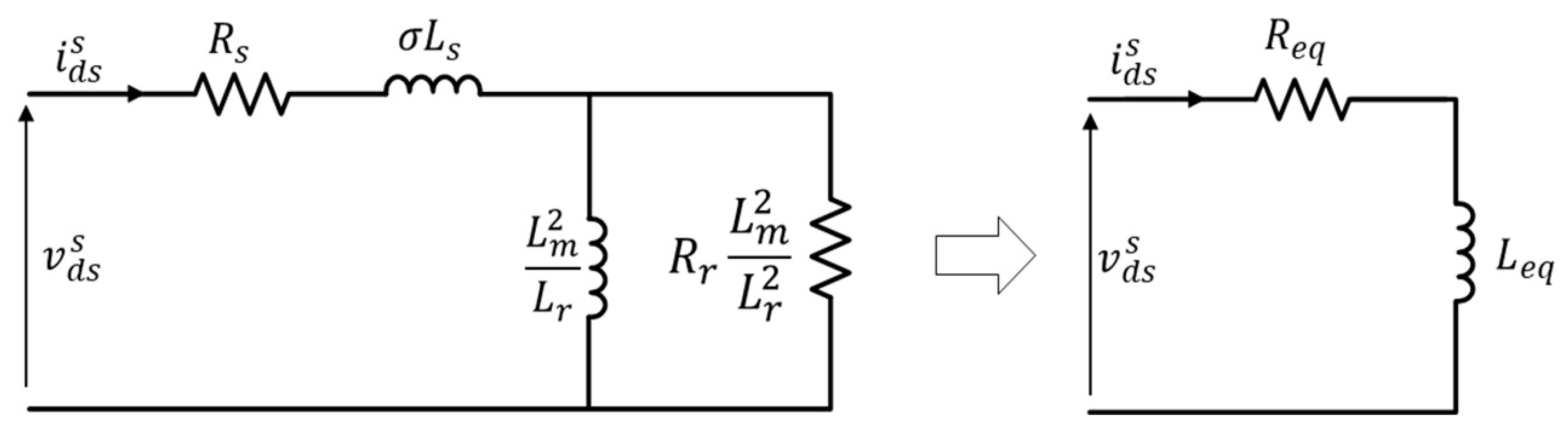
Figure 3 shows a simplified stationary
d-axis inverse-Γ equivalent circuit of an induction motor with high-frequency voltage signal injection at standstill. From the simplified model shown in
Figure 3, the
d-axis voltage and current equation is described by Equations (1) and (2), respectively.
where
and
are the
d-axis stator voltage and current, respectively, the equivalent resistance and inductance are denoted by
and
, respectively, while the magnitude of the stator current and its angular frequency are represented by
and
, respectively. Based on Equations (1) and (2), the multiplication of the voltage and the current gives us (3).
If a low-pass filter is applied, the average value of Equation (3) can be represented by Equation (4).
Based on Equation (2), the square of the current magnitude in Equation (4) gives us Equations (5) and (6).
By putting Equation (6) into Equation (4) the equivalent resistance becomes Equation (7).
Based on the previous results, the voltage Equation (1) can be rewritten as in Equation (8).
In the same way as the result in Equation (4), the low-pass filtered value of Equation (8) can be simplified as in Equation (9).
From Equation (9), the equivalent inductance is shown by Equation (10).
As mentioned before, since equivalent inductance is almost equal to leakage inductance ( for a rotating three phase induction motor, the equivalent inductance employed in this process can be used for the proposed stator inductance identification process.
3.2. Proposed Stator Inductance Identification Process
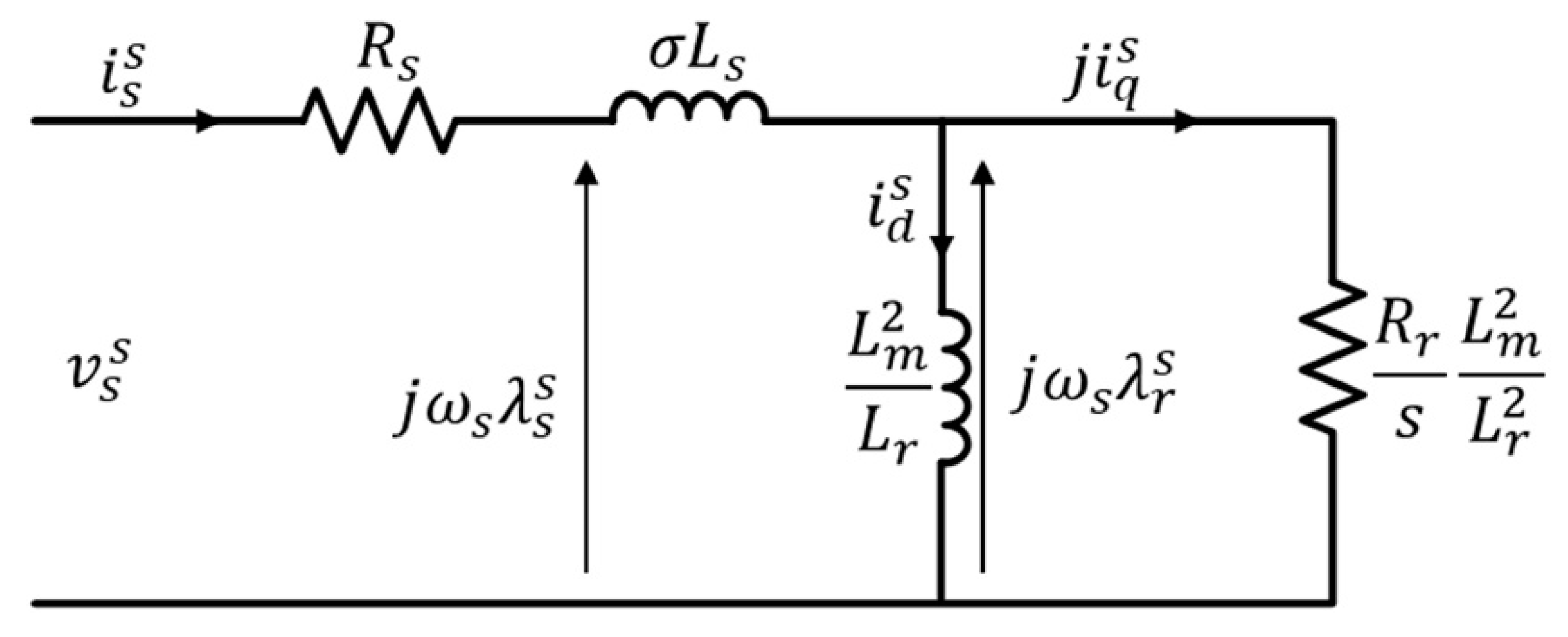
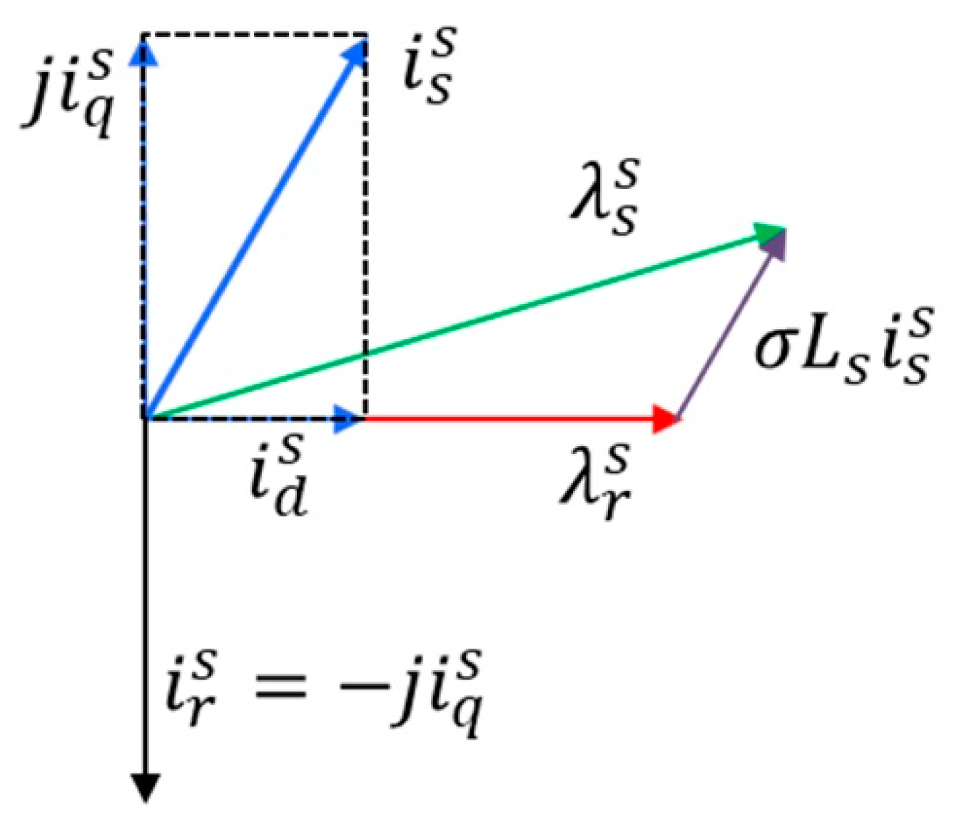
In order to obtain the stator inductance, the inverse-Γ equivalent circuit is analyzed in a steady state and its phasor diagram is as shown in
Figure 4 and
Figure 5.
In the inverse-
equivalent circuit shown in this figure, the stator and rotor flux linkages are calculated as in Equations (11) and (12).
where
and
are the stator and rotor fluxes, respectively, in a stationary reference frame. The stator and rotor currents are denoted by
and
, respectively. The magnetization and rotor inductance are represented by
and
, respectively.
From Equation (13), the leakage coefficient can be defined as .
Also, based on the phasor diagram shown in
Figure 5, the stator flux can be described as in Equation (14).
Using the flux linkage equation in Equation (11), Equation (14) can be rewritten as Equation (15).
From Equation (16), the stator inductance can be calculated as in Equation (16).
According to Equation (16), the stator inductance can be calculated based upon the stator flux, leakage inductance and the magnitude of current from the motor. Since the leakage inductance has already been estimated by the conventional method in Equation (10), and the current of the motor can be measured by sensors, the only parameter which needs to be estimated for stator inductance identification is the stator flux.
In this paper, we use a low frequency sinusoidal current to excite the IM in order to accurately estimate the magnitude of stator flux for the stator inductance identification process. The stator flux estimation process is described as follows.
In the IM drive system, the instantaneous reactive power can be calculated as in Equation (17).
where
are the output voltages in the stationary reference frame estimated from the DC link voltage and switching duty signals of the three-level SVPWM.
are motor currents in the stationary reference frame. After measuring the instantaneous reactive power, the result is filtered by a low-pass filter. This is because the magnitude of reactive power is needed for the calculation of the magnitude of stator flux. The magnitude of the stator current is calculated by Equation (18).
Also, during stator flux estimation, the stator flux (
) becomes very similar to the
d-axis stator flux (
) (
) in steady-state conditions. Furthermore, the field current is almost equal to the current magnitude, when the torque current is approximately zero (
) in the rotating reference frame. Therefore, reactive power is also calculated in a rotating reference frame as in Equation (19).
where
is the low-frequency angular speed,
is the
d-axis stator flux, which is equal to the estimated stator flux magnitude. After a low-pass filter is applied to the instantaneous reactive power Equation (17), it and the calculated reactive power in a rotating reference frame Equation (19) are almost equal in steady-state conditions. Therefore, the
d-axis stator flux can be calculated as in Equation (20).
The reason for this phenomenon is that low-frequency AC current is excited for the stator flux magnitude estimation while the slip of the induction motor is very low. After the stator flux is estimated, stator inductance can easily be identified based on the estimated stator flux in Equation (20), leakage inductance in Equation (10), and the magnitude of stator current in Equation (18), as shown in Equation (21).
From Equation (21), stator inductance is identified based on the magnitude of the stator flux, the field current with regulating stator flux to converge reference, and the estimated stator flux.
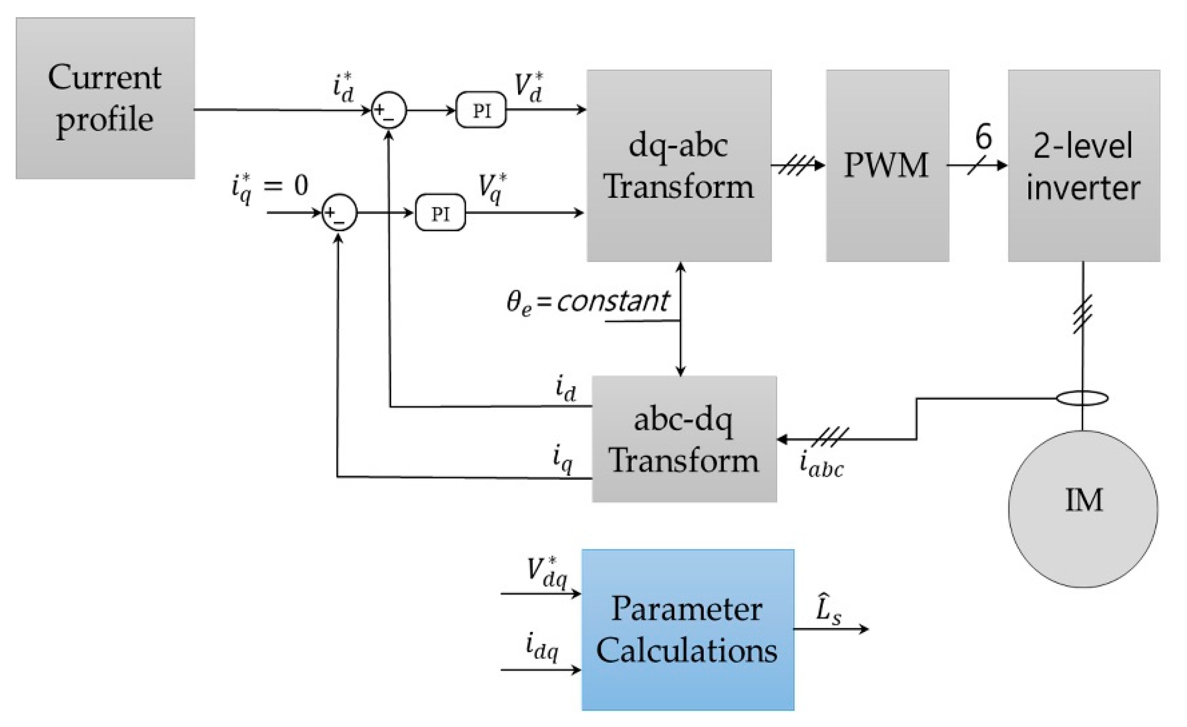
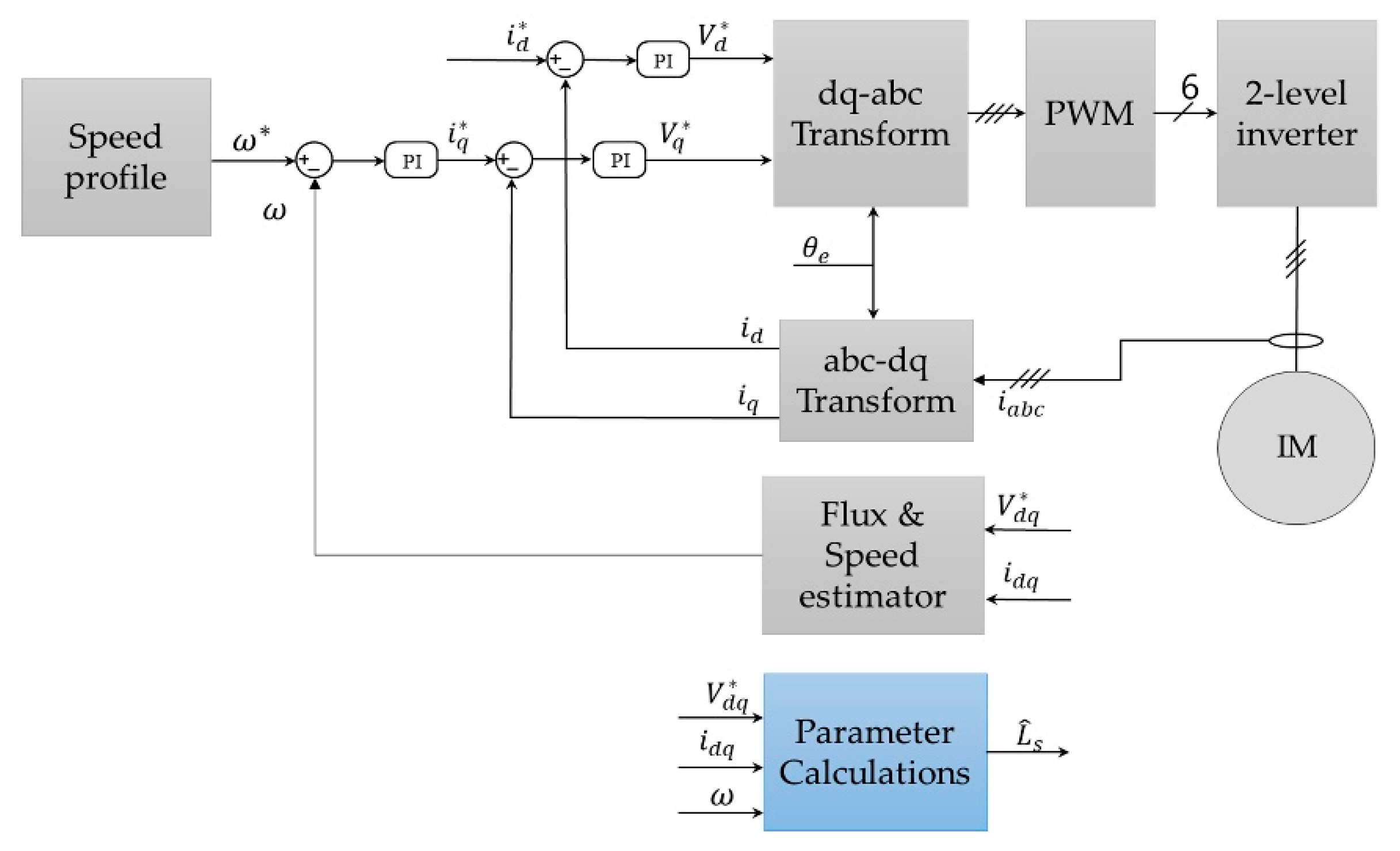
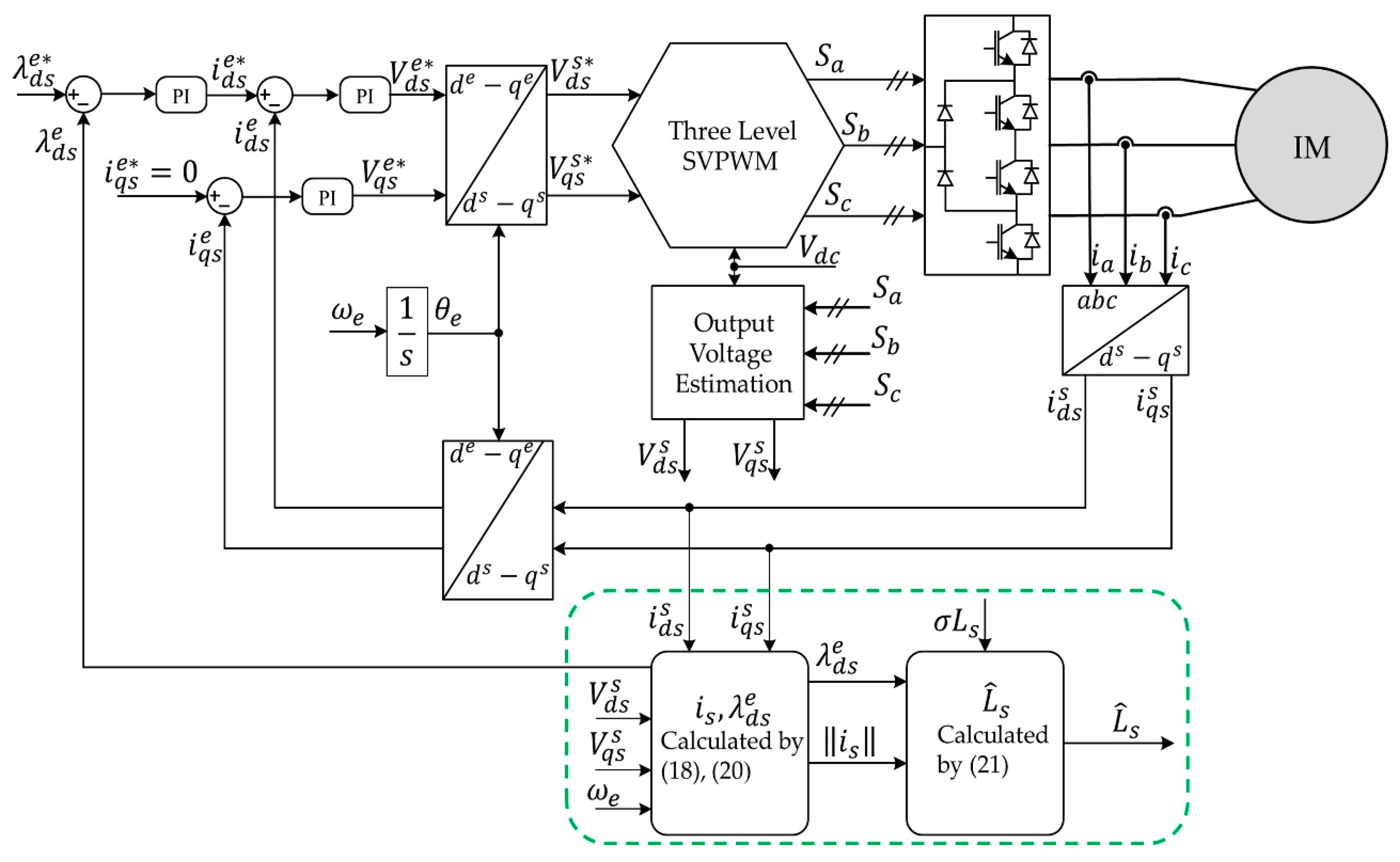
Figure 6 shows the proposed stator inductance identification process using the flux estimator and applied to a three-level NPC inverter-fed IM drive. As mentioned earlier, in the proposed identification process, the stator flux magnitude is estimated by the instantaneous reactive power when a low-frequency excitation current with a frequency similar to the slip frequency is injected into the IM.
The magnitude of the current is controlled by the stator flux regulator, and the reference of the stator flux is calculated from the rated stator flux based on the nameplate parameters, which comes from the ratio of the rated phase voltage and rated electrical angular speed. The output of the flux regulator generates the field current (d-axis current) reference for the current regulator, while the torque current (q-axis current) reference for the current regulator is set to zero. During this flux regulation process, the instantaneous reactive power is measured using the motor currents and output voltages of the inverter in the stationary reference frame.
The proposed method is suitable for three-level NPC inverter-fed IMs, since this method does not require compensation for nonlinearity from power switches. Furthermore, in variable load torque applications, low-speed rotational tests that generate very low load torque are almost the same as no-load conditions, which makes the proposed method more accurate in such applications. Also, the proposed identification process is robust to long cable (>100 m) connections between the inverter and the motor, as not only does it have no compensation for inverter non-linearity, but it can also be simply applied to various inverters with different rated voltage and power. Since, in some MV drive (three-level NPC topology) applications, wire distance from the inverter to the motor can be hundreds of meters, this is a significant advantage for the proposed method.
4. Simulation Results
In order to verify the proposed stator inductance identification method, PSIM-based simulations were performed. The proposed identification process was implemented in a three-level NPC inverter with a DC-link voltage of 600 V and 18.5 kW induction motor. The parameters used in both simulation and experiment for an 18.5 kW IM are set to the same values for direct comparison, as shown in
Table 1.
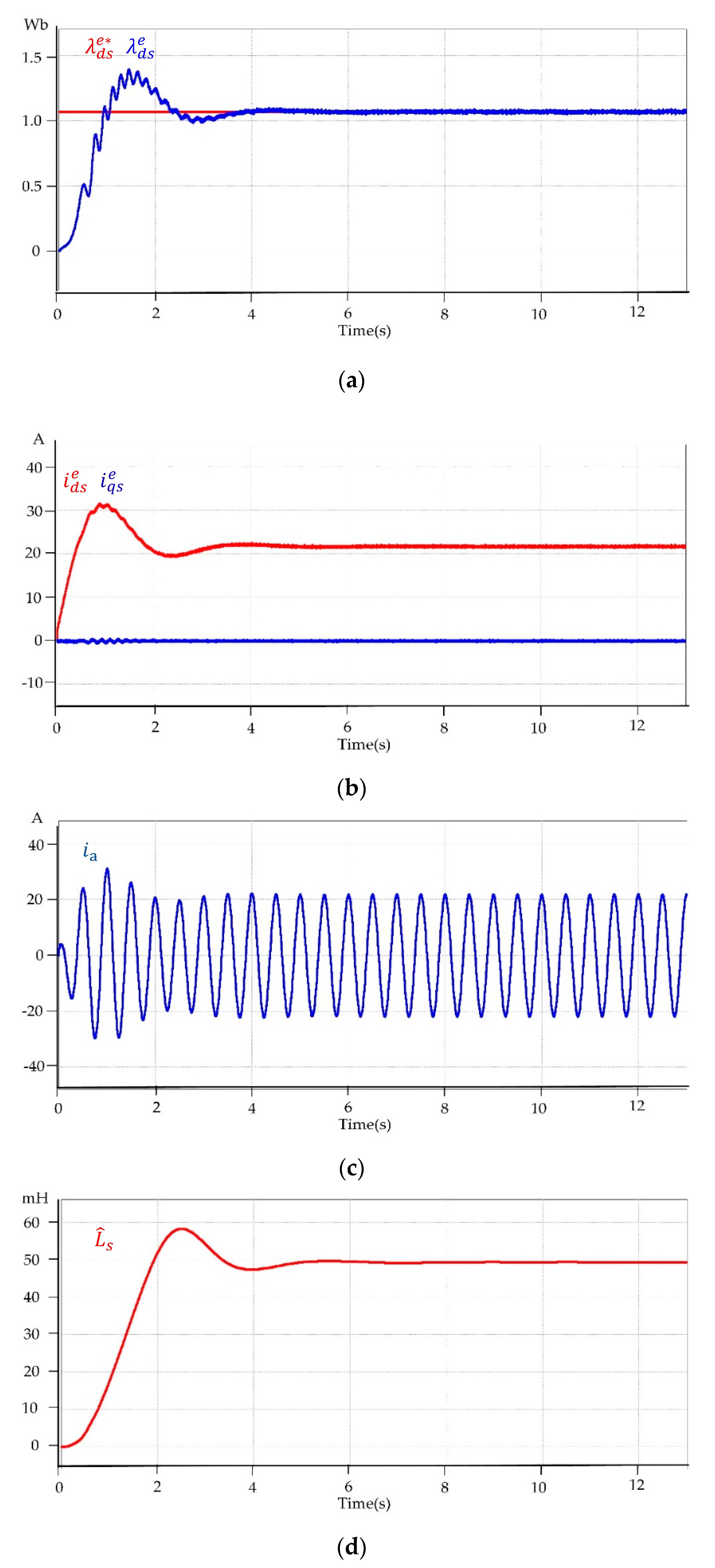
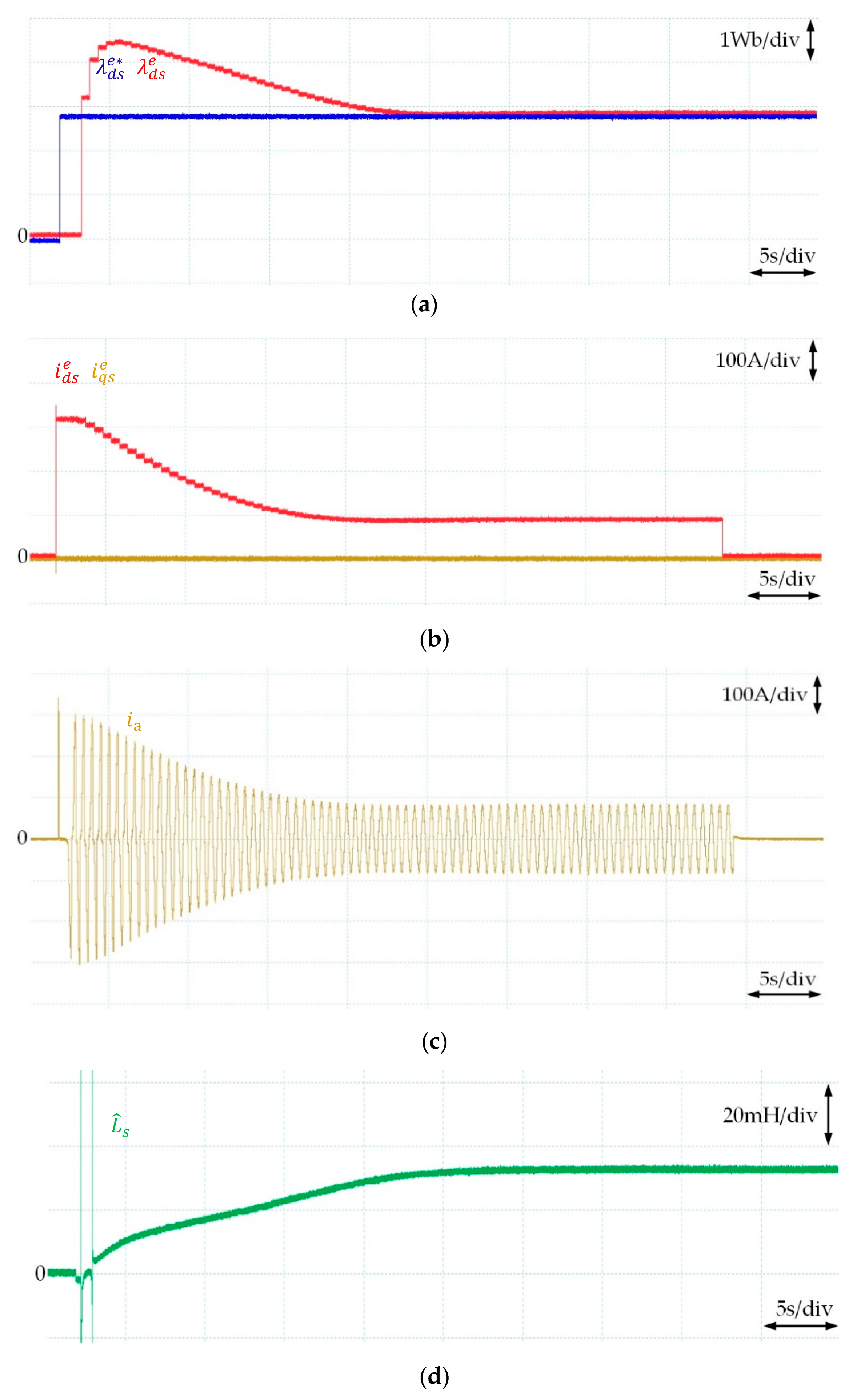
Simulation results using the proposed stator inductance identification scheme are shown in
Figure 7. The reference stator flux (
) is set to 1.07 Wb, and the estimated stator flux (
) calculated by Equation (20) is shown in
Figure 7a. After the transient state of the proposed identification process, the estimated stator flux is converged to the reference stator flux by the flux regulator in the block diagram, as shown in
Figure 6. Since the output of the flux regulator is used as the
d-axis reference of the current regulator, and the
q-axis reference is set to zero to satisfy the approximation in Equation (19), the transient behavior of the stator current is only depending on the error of the flux, as shown in
Figure 7b,c. Since the injected frequency for the proposed method is set to 2 Hz, the frequency of the a-phase stator current is alternating by 2 Hz, as shown in
Figure 7c. Based on the estimated stator flux and the magnitude of the current, the stator inductance is identified using Equation (21), as shown in
Figure 7d. Since the stator inductance can be properly identified after the stator flux is converged to its reference value, the steady-state value is used for the identified stator inductance.
As shown in
Figure 7d, the stator inductance is well identified, and almost the same as the nominal stator inductance value. The simulation results for the proposed stator inductance identification method are shown in
Table 2. The stator inductance identification error is less than 1%, and was identified within 13 s.
5. Experimental Results
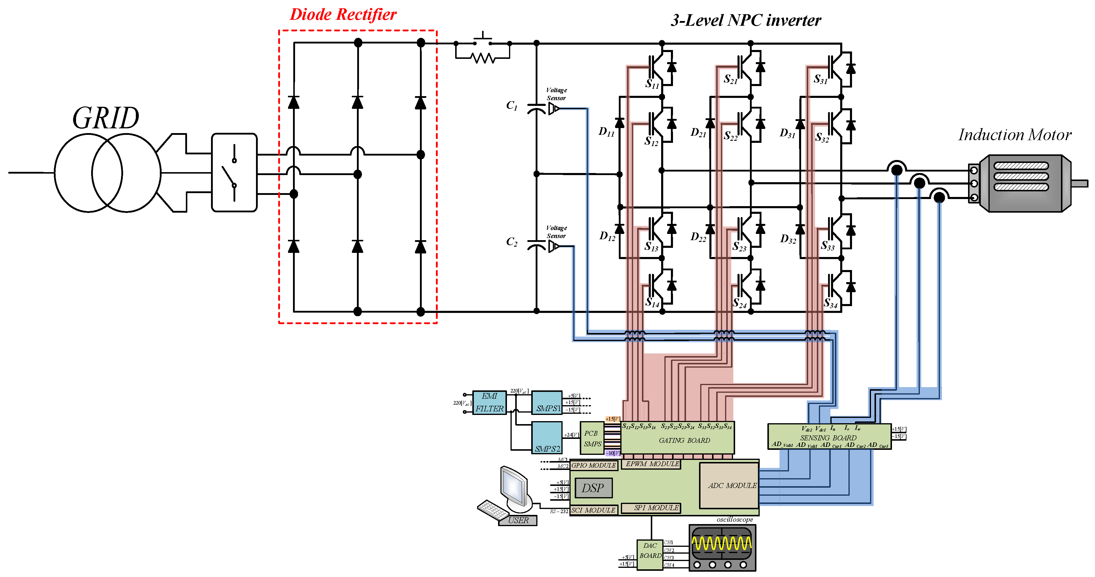
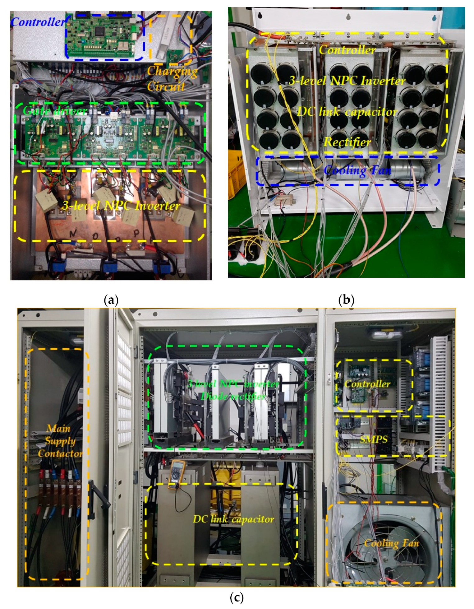
In the experiment, the proposed identification process was implemented for three different types of induction motor with three-level NPC inverters to verify the feasibility of the proposed method. The hardware setup for the experiment consisted of the main circuit breaker, 6-pulse diode rectifier, charging circuit, DC-link capacitor, three-level NPC inverter, DSP controller (TMS320F28335), voltage and current sensors, as well as the IM, as shown in
Figure 8.
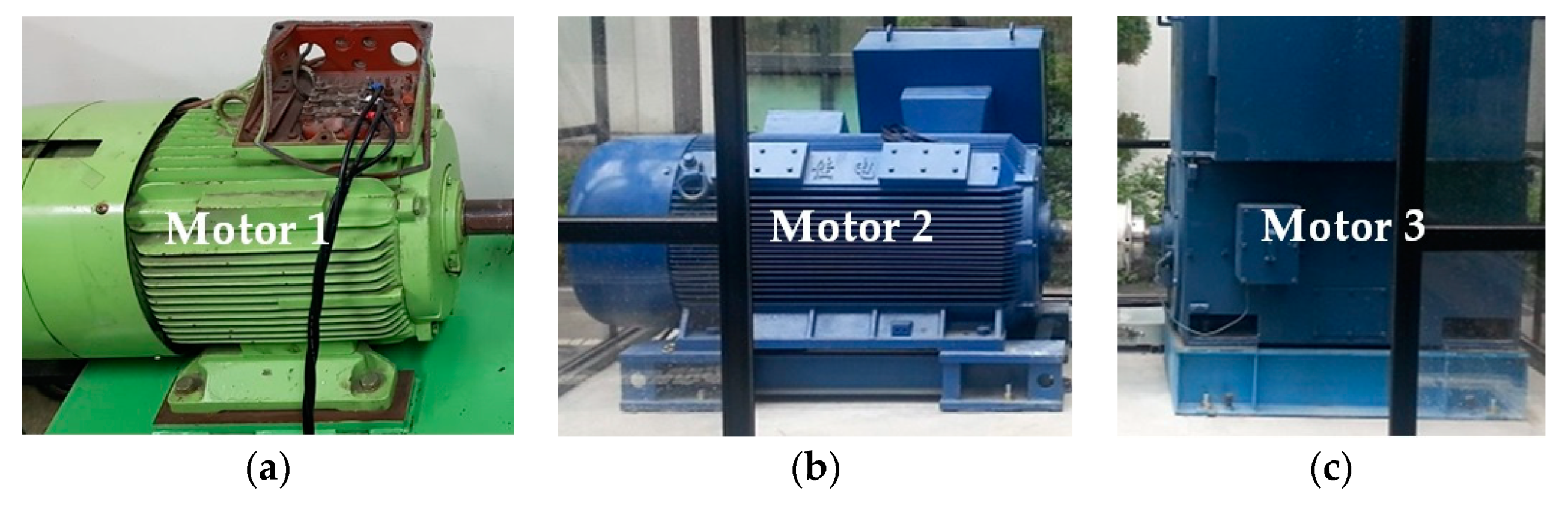
Figure 9 shows the three different types of IM to be used for verification of the proposed identification process. Their nameplate parameters and rated stator flux are given in
Table 3. Three different rated stator fluxes of IMs are calculated by the ratio of the rated phase voltage and the rated electrical angular speed. Furthermore, three different types of three-level NPC inverter, shown in
Figure 10, are used and their parameters are listed in
Table 4.
In the experiment, a DC-link balancing algorithm with three-level SVPWM was applied [
17,
18]. Also, the switching frequencies for the 1140 V, 3300 V and 440 V three-level NPC inverters are 1.2 kHz, 1.5 kHz and 2 kHz, respectively. In addition, because of their size, the 3300 V and 1140 V IMs are located outside of the building, but their inverters are installed inside of the building. For this reason, the 3300 V IM has a wire length of 180 m and the 1140 V IM has a wire length of 100 m. Due to its high-current capability, the 3300 V three-level NPC inverter uses a water cooling system. In the flux regulator, the gains are set to have low bandwidth, because the estimated stator flux is low-pass filtered to remove noise from power and currents. During the identification of stator inductance, the angular frequency of the sinusoidal AC current is set to around 2 Hz. Experimental results using the proposed stator inductance identification scheme with three different types of IM are shown in
Figure 11,
Figure 12 and
Figure 13, respectively.
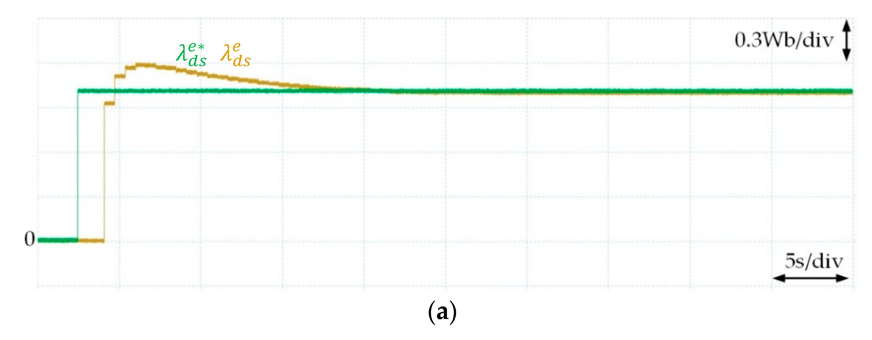
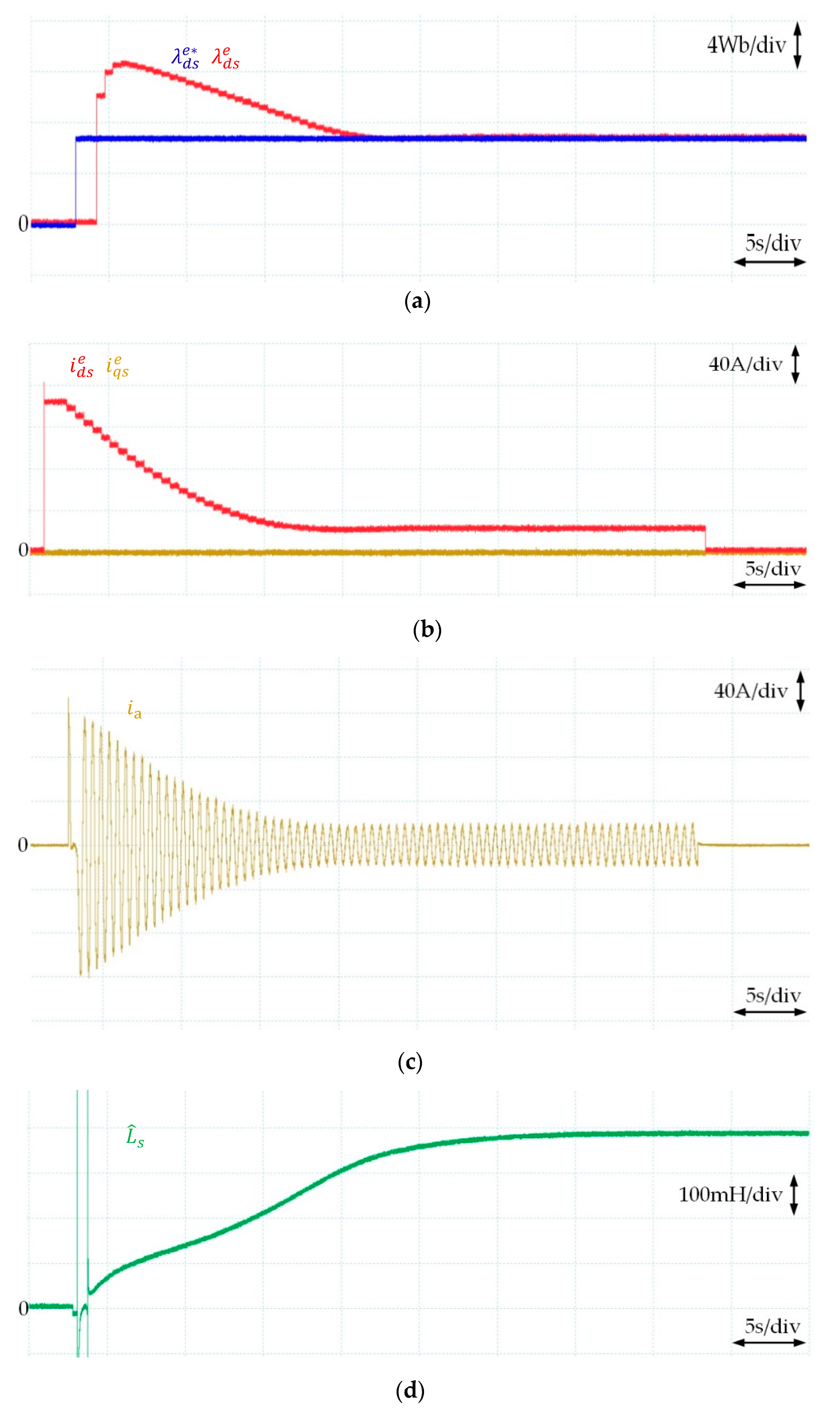
Figure 11a shows the waveform of the reference stator flux (
) of Motor 1 in
Table 1 and estimated stator flux (
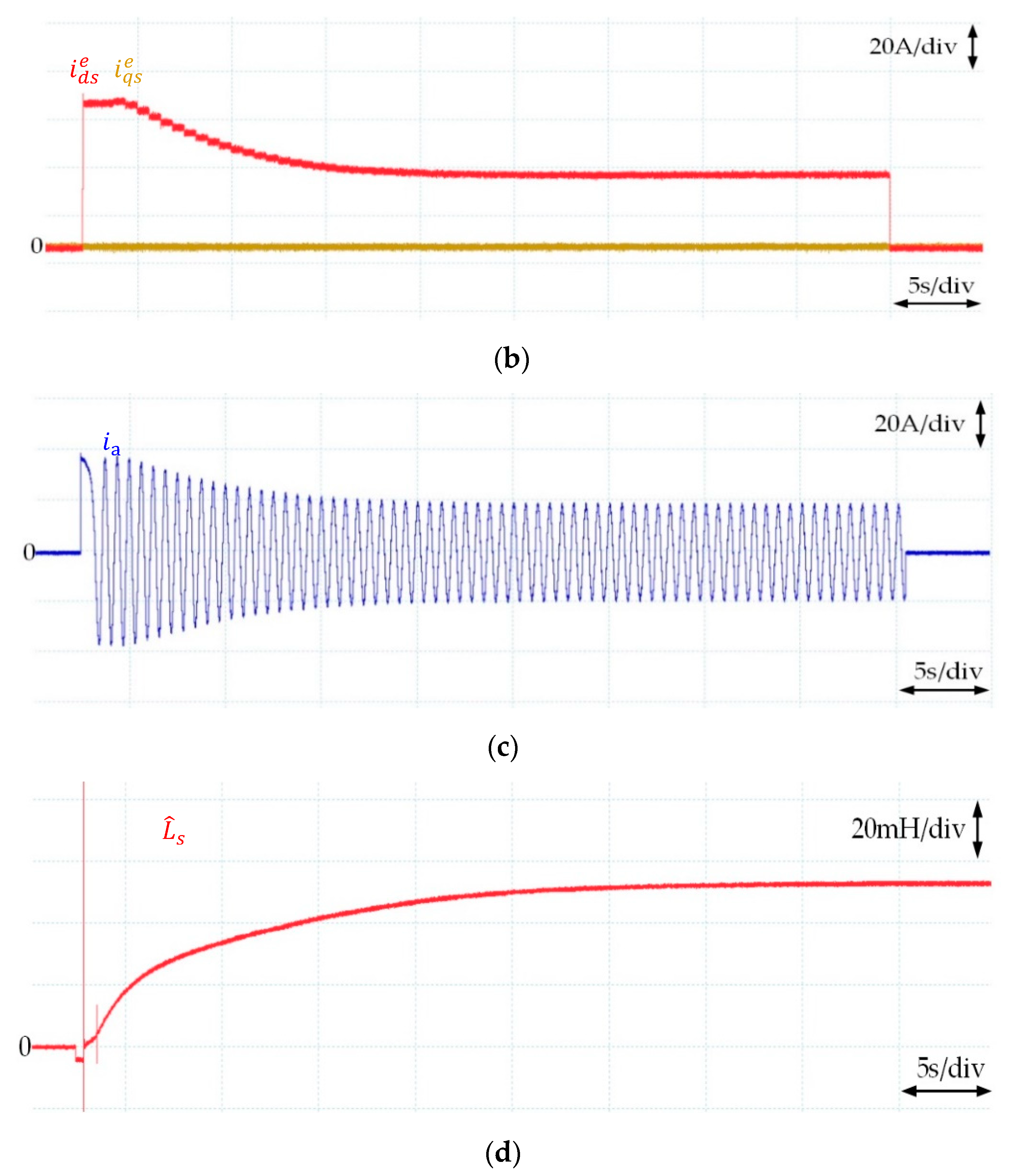
) in the proposed stator inductance identification procedure. The reference stator flux for this experiment is set to 1.07 Wb, the same value as simulation, and the estimated stator flux is calculated using Equation (20). As shown in this figure, the stator flux is converged to the reference value after the transient-state as the same as the simulation result. Also, the stator current is regulated to have the steady-state value that makes the estimated stator flux value the same value as its reference, 1.07 Wb in this case, and the
q-axis current is regulated to zero because of the approximation in Equation (19), as shown in
Figure 11b. In
Figure 11c, the a-phase current of the motor is shown, which magnitude is the same as the
d-axis current shown in
Figure 11b, and is alternating in 2 Hz, injected low-speed sinusoidal frequency. Since the regulator is tuned differently, the behavior in transient-state could be different according to the experimental environment. However, it does not affect the performance of the proposed identification method, because the proposed method is using the steady-state values.
Figure 11d shows the estimated stator inductance based on Equation (21) during the proposed identification procedure. In the transient-state in this figure, it seems that there are some spikes in the estimated stator inductances. The reason for this phenomenon is because, as shown in Equation (21), low-pass filtered stator current magnitude is on the denominator to estimate the stator inductance, and initially, the output value of this stator current is zero. Therefore, the excessive value of the estimated stator inductance occurs in the initial-state, causing the overflow to the data. However, this phenomenon does not affect the performance of the proposed method because, as mentioned above, the proposed method is only using the steady-state value.
The experimental results, shown in
Figure 12 and
Figure 13, are following the same procedure as
Figure 11, but Motor 2 and Motor 3 in
Table 3 are used respectively instead of Motor 1. In
Figure 12a, the reference stator flux (
) is set to 2.96 Wb for Motor 2 and the result of the estimated stator flux (
) is shown.
Figure 12b,c show the stator current response during the proposed identification procedure. However, as shown in
Figure 12c, the initial current of the motor seems to have a spike that did not appear in previous results. This is because of the experimental environment limitation. Since diameters of connected wires for Motors 2 and 3 are much wider than the wire for Motor 1, an AC current probe (Tektronix) is used for measuring the currents for Motors 2 and 3 instead of the DC current probe (Lecroy), which is used for Motor 1, because the DC current probe does not fit. Since the initial current, in this case, is not considered as an AC value because of its low frequency, the AC probe could not properly measure initial current, and that is the reason why the stator current in
Figure 12c looks like they are having the current spikes while there is no current spike, but only low-frequency stator current is flowing.
Figure 12d shows the identified stator inductance for Motor 2 based on the proposed method. As the same as
Figure 11d, there are some spikes in transient-state, but the steady-state value is converged to a single point.
Motor 3 in
Table 3 (560 kW/3300 V) is most commonly used for medium voltage application, and its rated (reference) stator flux (
) is set to 7.4 Wb, much larger than Motors 1 and 2. Since the experimental environments for Motors 2 and 3 are very similar, the experimental results shown in
Figure 12 and
Figure 13 have very similar behavior. As the flux is regulated based on the flux regulation system shown in
Figure 6, the estimated stator flux and
dq-axis stator currents are converged, as shown in
Figure 13a,b. Since the AC current probe is also used for this experiment, the incorrect current spike appears in a-phase current of Motor 3, as well as shown in
Figure 13c. Also, the spikes from the overflow exist in the transient-state of the estimated stator inductance, as shown in
Figure 13d, but a constant identified value for stator inductance appears in the steady-state.
The experimental results of the identified stator inductances from the proposed method are shown in
Table 5. The nominal value of the stator inductance is identified based on a pre-running no-load test with acceleration and deceleration profiles for the rated speed, which is the most accurate method. As shown in
Table 5, the identification error is less than 10% for all IMs.
Therefore, no matter what kind of IM is used, the proposed method can identify the stator inductance accurately, which verifies its usefulness.


