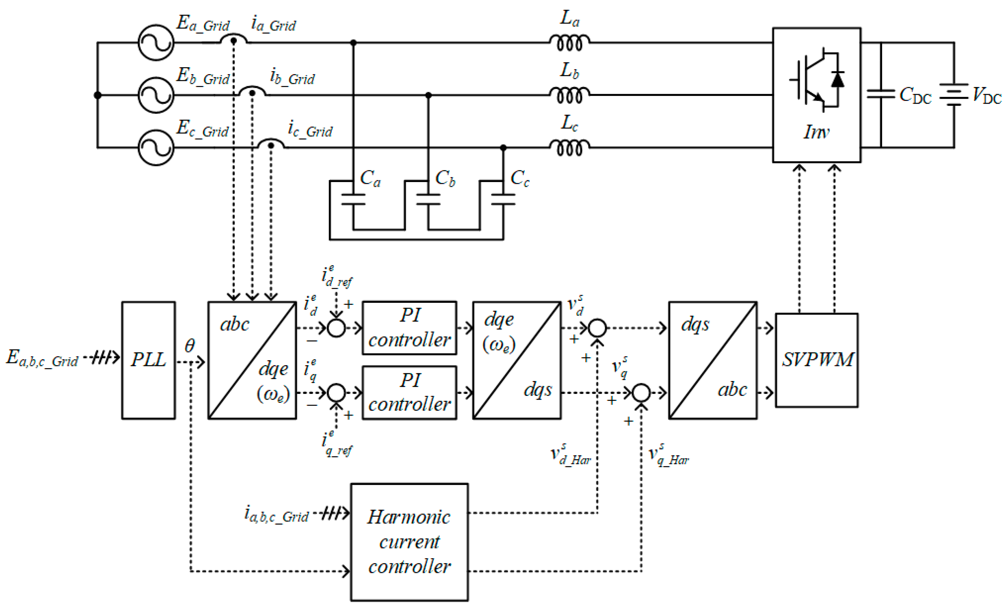
Figure 1.
Block diagram of current control strategy with harmonic compensation method. PI: proportional integral. PLL: phase locked loop. SVPWM: space vector pulse width modulation
Figure 1.
Block diagram of current control strategy with harmonic compensation method. PI: proportional integral. PLL: phase locked loop. SVPWM: space vector pulse width modulation
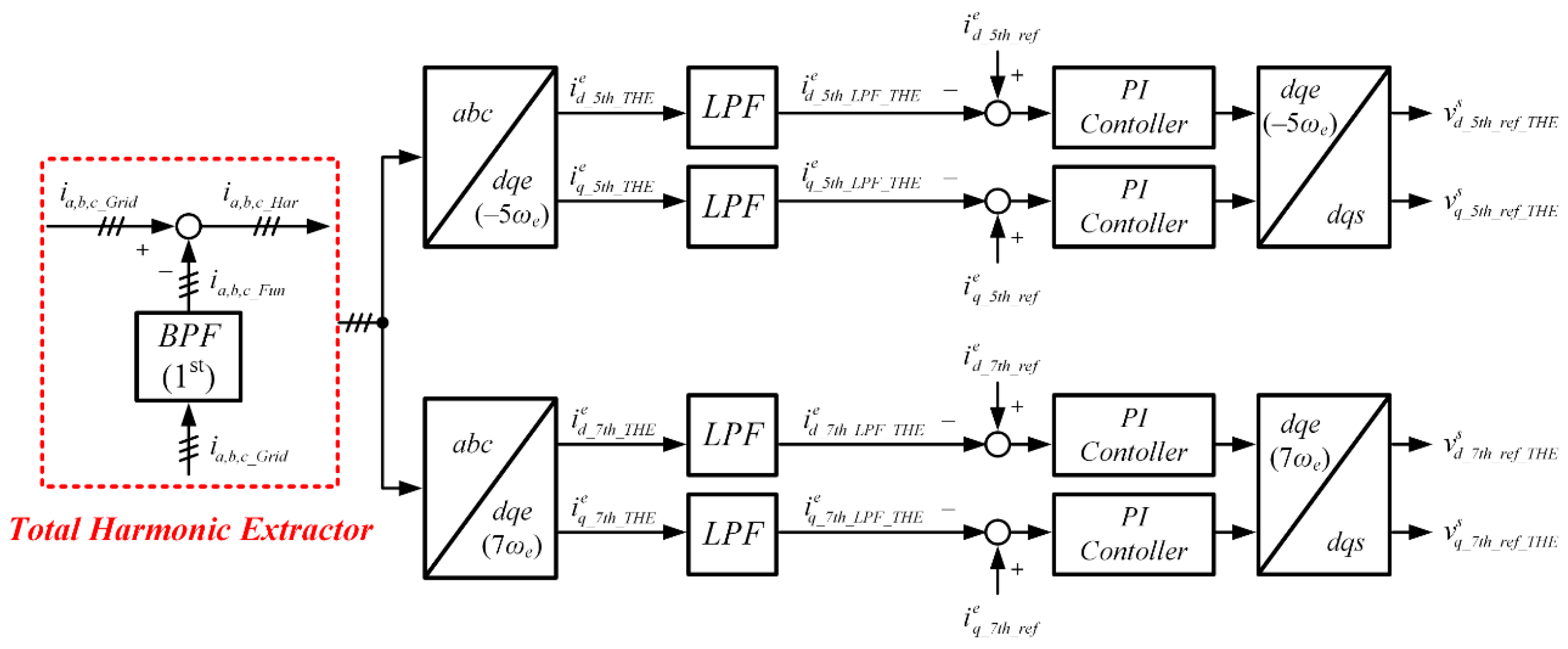
Figure 2.
Block diagram of conventional harmonic compensation method. LPF: low pass filter.
Figure 2.
Block diagram of conventional harmonic compensation method. LPF: low pass filter.
Figure 3.
Bode plot of the LPF for the harmonic compensation method (ωcL = 6.283 rad/sec).
Figure 3.
Bode plot of the LPF for the harmonic compensation method (ωcL = 6.283 rad/sec).
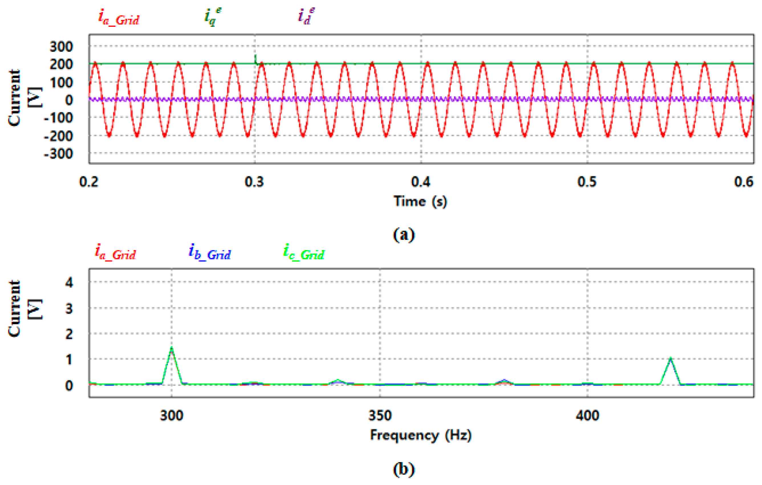
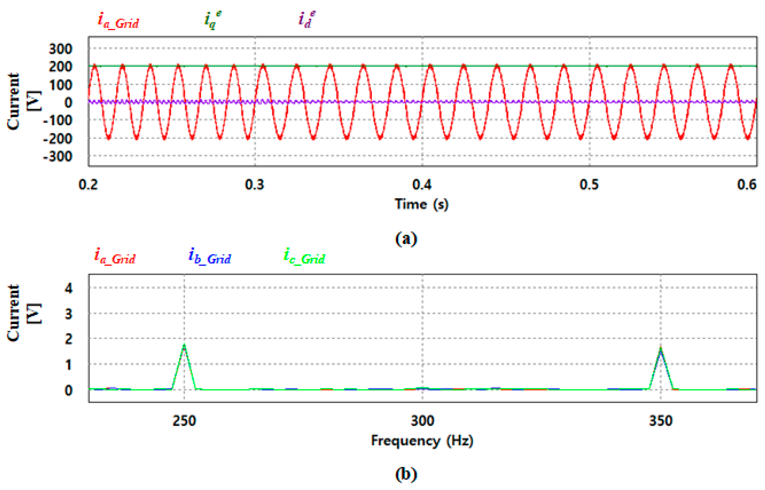
Figure 4.
Waveforms of fundamental current control with a distorted grid voltage: (a) output current, and (b) FFT (fast frequency transform) analysis results.
Figure 4.
Waveforms of fundamental current control with a distorted grid voltage: (a) output current, and (b) FFT (fast frequency transform) analysis results.
Figure 5.
Extracted harmonic currents using the conventional method.
Figure 5.
Extracted harmonic currents using the conventional method.
Figure 6.
Block diagram of the THE (total harmonic extractor) method. BPF: bandpass filter.
Figure 6.
Block diagram of the THE (total harmonic extractor) method. BPF: bandpass filter.
Figure 7.
Bode plot of the BPF according to bandwidth in the THE method.
Figure 7.
Bode plot of the BPF according to bandwidth in the THE method.
Figure 8.
Harmonic currents extracted using the THE method.
Figure 8.
Harmonic currents extracted using the THE method.
Figure 9.
Block diagram of the SHE (selected harmonic extractor) method.
Figure 9.
Block diagram of the SHE (selected harmonic extractor) method.
Figure 10.
Bode plot of the BPF according to bandwidth in the SHE method: (a) center frequency ωcB = 1885.0 rad/sec, (b) center frequency ωcB = 2638.9 rad/sec.
Figure 10.
Bode plot of the BPF according to bandwidth in the SHE method: (a) center frequency ωcB = 1885.0 rad/sec, (b) center frequency ωcB = 2638.9 rad/sec.
Figure 11.
Harmonic currents extracted using the SHE method.
Figure 11.
Harmonic currents extracted using the SHE method.
Figure 12.
Simulation circuit configuration for the harmonic compensation method (three-level NPC inverter). NPC: neutral point clamped.
Figure 12.
Simulation circuit configuration for the harmonic compensation method (three-level NPC inverter). NPC: neutral point clamped.
Figure 13.
Simulation waveforms when applying the conventional method: (a) output current, (b)FFT analysis result.
Figure 13.
Simulation waveforms when applying the conventional method: (a) output current, (b)FFT analysis result.
Figure 14.
Simulation waveforms when applying the THE method: (a) output current, (b) FFT analysis result.
Figure 14.
Simulation waveforms when applying the THE method: (a) output current, (b) FFT analysis result.
Figure 15.
Simulation waveforms when applying the SHE method: (a) output current, (b) FFT analysis result.
Figure 15.
Simulation waveforms when applying the SHE method: (a) output current, (b) FFT analysis result.
Figure 16.
Conventional harmonic compensation method (grid voltage: 311 V → 250 V): (a) three-phase grid voltage, a-phase current, and d-q axis current; (b) FFT analysis result of three-phase current.
Figure 16.
Conventional harmonic compensation method (grid voltage: 311 V → 250 V): (a) three-phase grid voltage, a-phase current, and d-q axis current; (b) FFT analysis result of three-phase current.
Figure 17.
Proposed harmonic compensation method (grid voltage: 311 V → 250 V): (a) three-phase grid voltage, a-phase current, and d-q axis current; (b) FFT analysis result of three-phase current.
Figure 17.
Proposed harmonic compensation method (grid voltage: 311 V → 250 V): (a) three-phase grid voltage, a-phase current, and d-q axis current; (b) FFT analysis result of three-phase current.
Figure 18.
Conventional harmonic compensation method (grid frequency: 60 Hz → 50 Hz): (a) three-phase grid voltage, a-phase current, and d-q axis current; (b) FFT analysis result of three-phase current.
Figure 18.
Conventional harmonic compensation method (grid frequency: 60 Hz → 50 Hz): (a) three-phase grid voltage, a-phase current, and d-q axis current; (b) FFT analysis result of three-phase current.
Figure 19.
Proposed harmonic compensation method (grid frequency: 60 Hz → 50 Hz): (a) three-phase grid voltage, a-phase current, and d-q axis current; (b) FFT analysis result of three-phase current.
Figure 19.
Proposed harmonic compensation method (grid frequency: 60 Hz → 50 Hz): (a) three-phase grid voltage, a-phase current, and d-q axis current; (b) FFT analysis result of three-phase current.
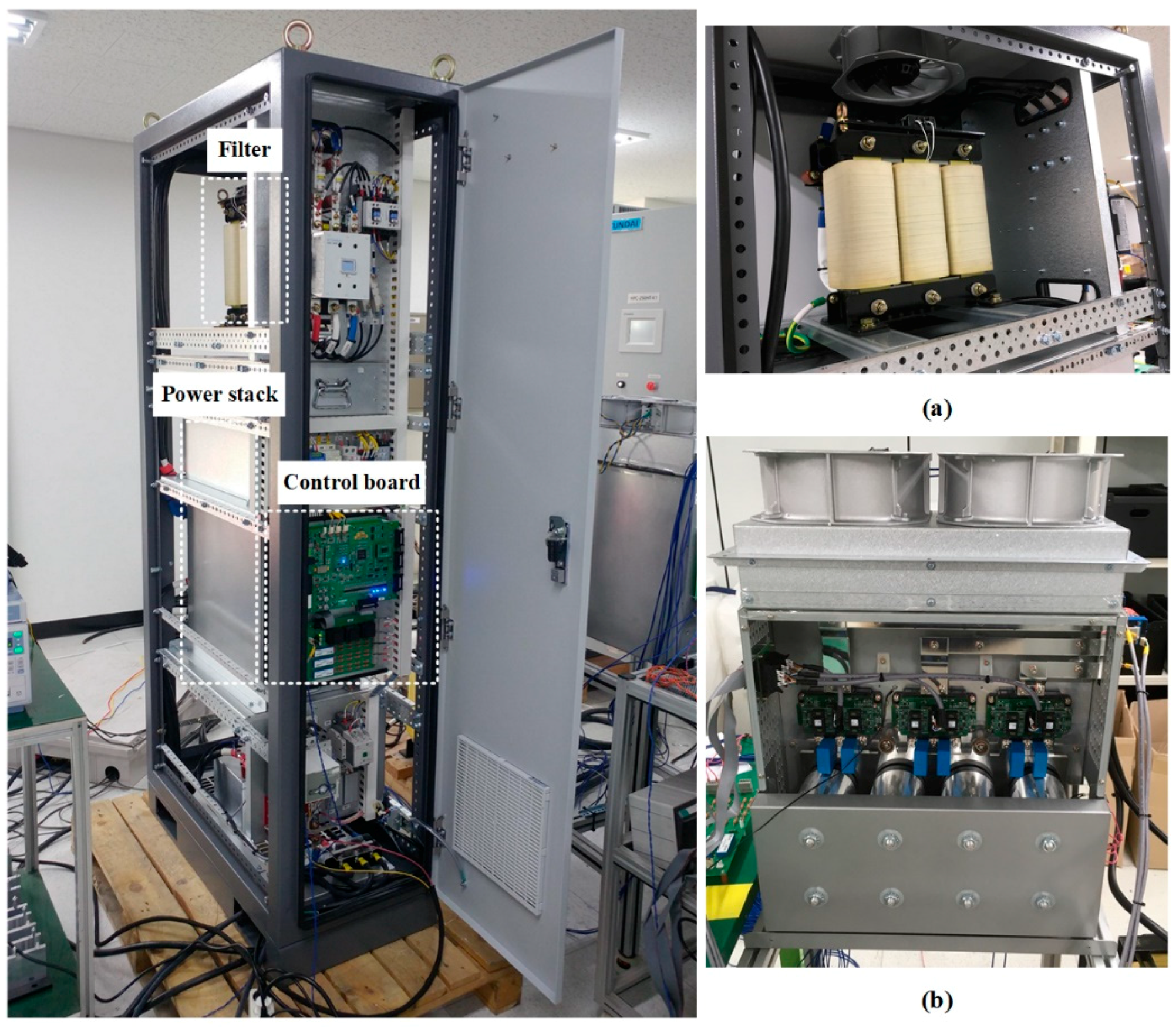
Figure 20.
Experimental setup for the proposed harmonic compensation method: (a) filter of PCS (power control system), (b) PCS power stack.
Figure 20.
Experimental setup for the proposed harmonic compensation method: (a) filter of PCS (power control system), (b) PCS power stack.
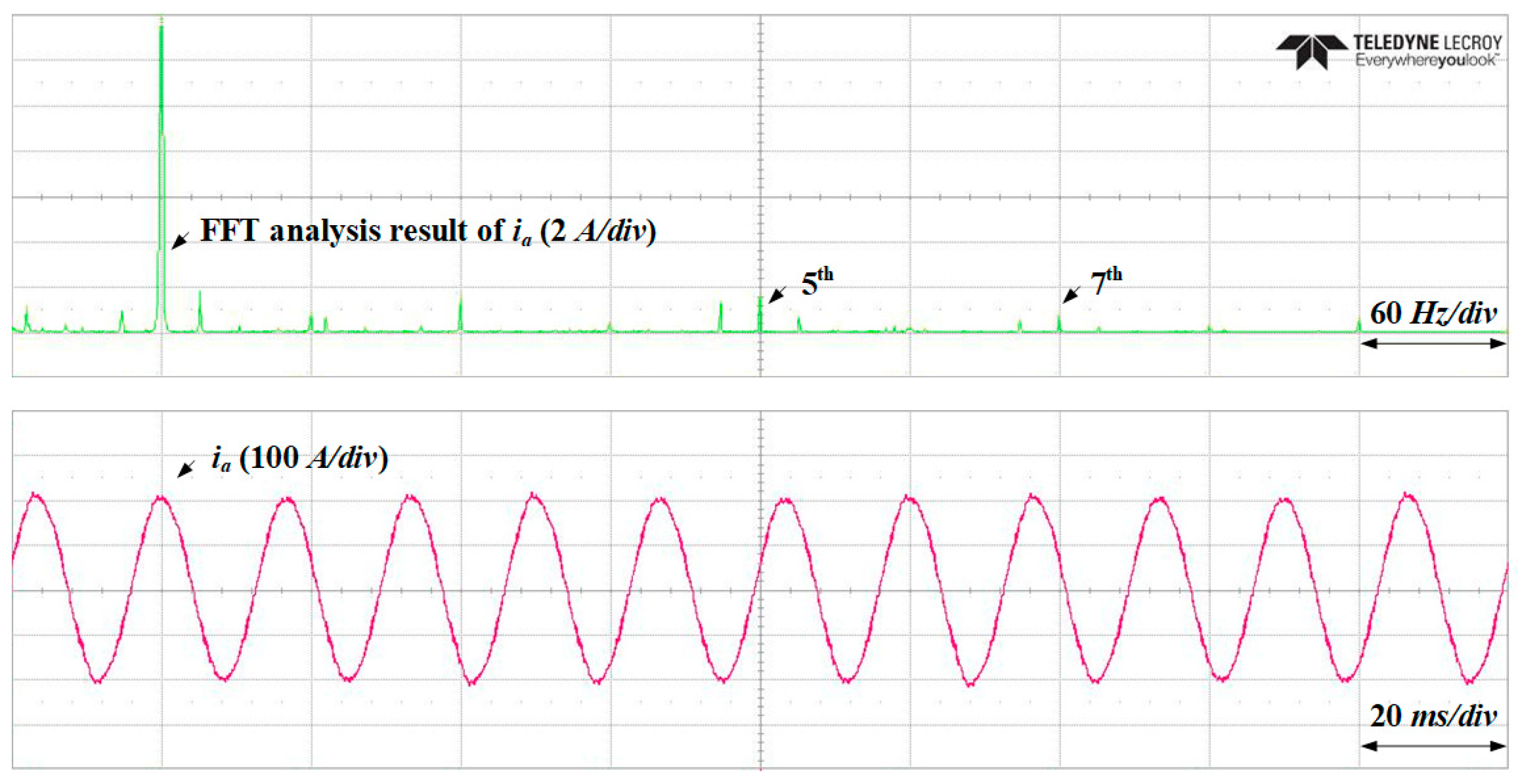
Figure 21.
Experimental results when no harmonic compensation method is applied.
Figure 21.
Experimental results when no harmonic compensation method is applied.
Figure 22.
Experimental results when a harmonic compensation method is applied: conventional method.
Figure 22.
Experimental results when a harmonic compensation method is applied: conventional method.
Figure 23.
Experimental results when a harmonic compensation method is applied: THE method.
Figure 23.
Experimental results when a harmonic compensation method is applied: THE method.
Figure 24.
Experimental results when a harmonic compensation method is applied: SHE method.
Figure 24.
Experimental results when a harmonic compensation method is applied: SHE method.
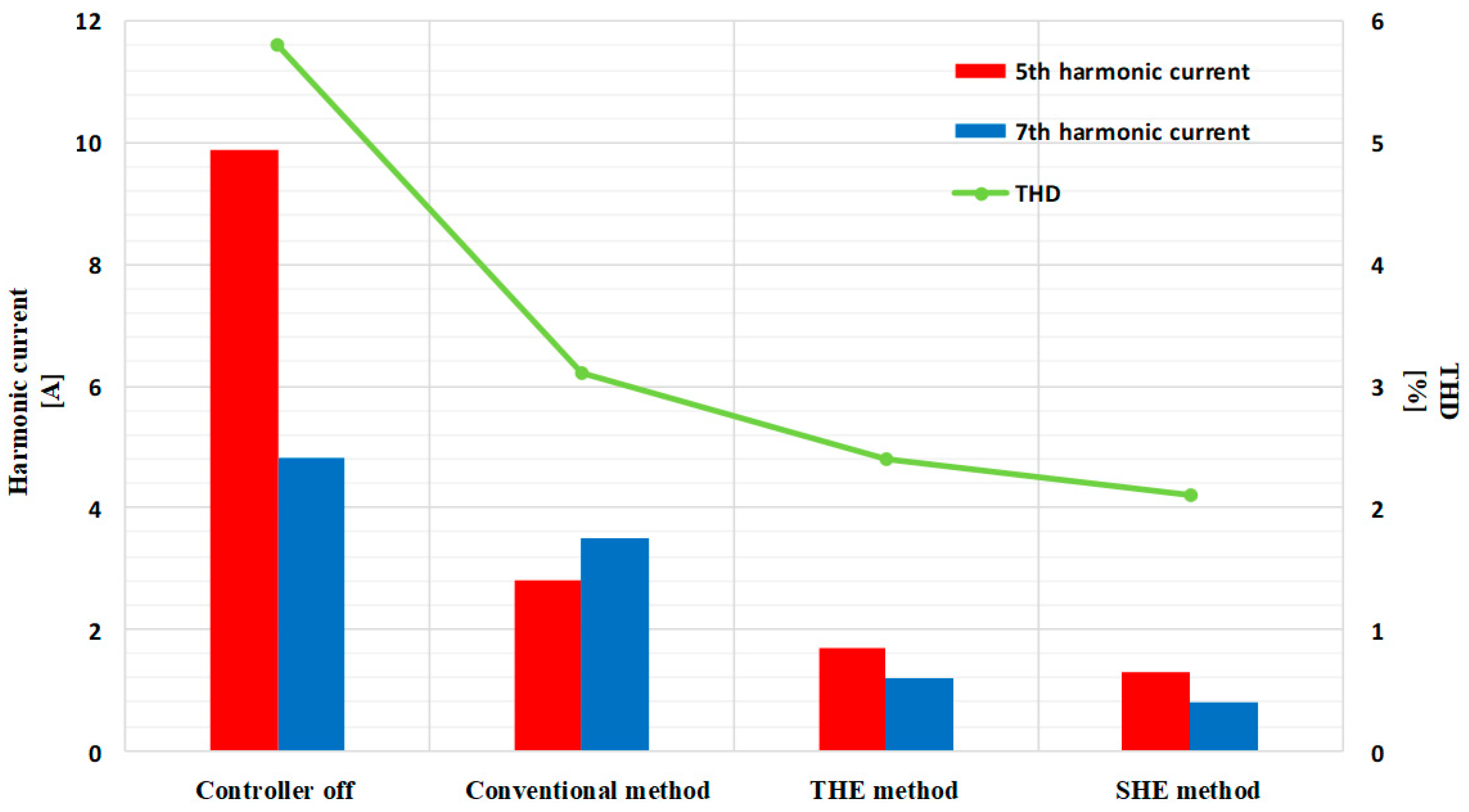
Figure 25.
Experimental results analysis of output currents based on harmonic compensation method.
Figure 25.
Experimental results analysis of output currents based on harmonic compensation method.
Table 1.
Sequence of harmonic currents.
Table 1.
Sequence of harmonic currents.
| Categories | Order |
|---|
| Positive sequence | 1st, 7th, 13th, ··· |
| Negative sequence | 5th, 11th, 17th, ··· |
| Zero sequence | 3rd, 9th, 15th, ··· |
Table 2.
FFT analysis results under the distorted grid condition.
Table 2.
FFT analysis results under the distorted grid condition.
| Phase | Fifth Harmonic Current | Seventh Harmonic Current |
|---|
| A | 7.43 A | 6.42 A |
| B | 7.50 A | 6.36 A |
| C | 7.38 A | 6.42 A |
| Average | 7.44 A | 6.40 A |
Table 3.
Harmonic signal ratio of each harmonic compensator.
Table 3.
Harmonic signal ratio of each harmonic compensator.
| Categories | Fifth Harmonic Current | Seventh Harmonic Current |
|---|
| Conventional method | 0.24 | 0.23 |
| THE method | 0.48 | 0.57 |
| SHE method | 0.98 | 0.83 |
Table 4.
Simulation parameters.
Table 4.
Simulation parameters.
| Parameters | Values | Units |
|---|
| Grid voltage (Ea,b,c_Grid) | 220 | Vrms |
| Grid frequency (fGrid) | 60 | Hz |
| Filter inductor (La,b,c) | 0.29 | mH |
| Filter capacitor (Ca,b,c) | 91.84 | µH |
| DC-link capacitance (CDC) | 3200 | μF |
| DC-link voltage (VDC) | 600 | V |
| Switching frequency (fsw) | 4.8 | kHz |
| Sampling time (Tsamp) | 208.33 | µs |
Table 5.
Performances of the THE method for different bandwidths.
Table 5.
Performances of the THE method for different bandwidths.
| Categories | Fifth Harmonic Current | Seventh Harmonic Current | THD |
|---|
| Bandwidth = 100 Hz | 0.28 A | 0.24 A | 4.61% |
| Bandwidth = 50 Hz | 0.24 A | 0.22 A | 4.61% |
| Bandwidth = 10 Hz | 0.26 A | 0.21 A | 4.61% |
Table 6.
Performances of the SHE method for different the bandwidths.
Table 6.
Performances of the SHE method for different the bandwidths.
| Categories | Fifth Harmonic Current | Seventh Harmonic Current | THD |
|---|
| Bandwidth = 100 Hz | 1.85 A | 1.27 A | 4.73% |
| Bandwidth = 50 Hz | 0.96 A | 0.69 A | 4.64% |
| Bandwidth = 10 Hz | 0.23 A | 0.11 A | 4.60% |
Table 7.
Analysis of output current depending on the harmonic compensation method.
Table 7.
Analysis of output current depending on the harmonic compensation method.
| Phase | Categories | Controller Off | Conventional Method | THE Method | SHE Method |
|---|
| A | 5th | 7.42 A | 3.39 A | 0.24 A | 0.20 A |
| 7th | 6.43 A | 2.47 A | 0.24 A | 0.11 A |
| THD | 6.66% | 5.12% | 4.61% | 4.60% |
| B | 5th | 7.52 A | 3.52 A | 0.26 A | 0.16 A |
| 7th | 6.38 A | 2.45 A | 0.22 A | 0.11 A |
| THD | 6.74% | 5.14% | 4.60% | 4.60% |
| C | 5th | 7.43 A | 3.51 A | 0.23 A | 0.34 A |
| 7th | 6.40 A | 2.55 A | 0.19 A | 0.11 A |
| THD | 6.66% | 5.13% | 4.62% | 4.60% |


