Article

Robust Current Predictive Control-Based Equivalent Input Disturbance Approach for PMSM Drive

1
College of Automation, Qingdao University, Qingdao 266071, China
2
School of Control Science and Engineering, Shandong University, Jinan 250061, China
*
Author to whom correspondence should be addressed.
Electronics 2019, 8(9), 1034; https://doi.org/10.3390/electronics8091034
Submission received: 11 August 2019 / Revised: 11 September 2019 / Accepted: 12 September 2019 / Published: 15 September 2019
(This article belongs to the Special Issue Advanced Control Systems for Electric Drives)

Abstract

:
The implementation and experimental validation of current control strategy based on predictive control and equivalent input disturbance approach is discussed for permanent magnet synchronous motor (PMSM) control system in the paper. First, to realize the current decoupling control, the deadbeat predictive current control technique is adopted in the current loop of PMSM. Indeed, it is well known that the traditional deadbeat current control cannot completely reject the disturbance and realize the zero error current tracking control. Then, according to the model uncertainties and the parameter variations in the motor, an equivalent input disturbance approach is introduced to estimate the lump disturbance in the system, which will be used in the feed-forward compensation. Thus, a compound current controller is designed, and the proposed algorithm reduces the tracking error caused by the disturbance; the robustness of the drive system is improved effectively. Finally, simulation and experiment are accomplished on the control prototype, and the results show the effectiveness of the proposed current control algorithm.

1. Introduction

Owning to the multiple advantages of high efficiency, high power density, and exceptional reliability, permanent magnet synchronous motor (PMSM) has been widely used in different applications [1], such as electric vehicle drive system, rail traffic, and robot. However, the main weakness of PMSM is the complex controller for its nonlinear and strong coupling characteristics. Therefore, the vector control strategy is employed for the practical applications in general. Consequently, a double closed-loop control method with the inner current loop and the out speed loop is formed. This paper mainly concentrates on solving the current control problem of PMSM in the face of different disturbance.
In general, the proportional plus integral (PI) current control method is popular for industrial applications and is not designed based on the mathematical model. The good performance of zero steady-state error and fixed switching frequency has promoted extensive industrial application. However, it may not meet the requirement in some special occasions, and the transient response may be limited. Meanwhile, it is a challenge for engineers to select the PI parameters by trial and error because of the large parameter uncertainties [2]. Thus, many approaches have been proposed for the motor drive system, such as, sliding mode variable structure control [3], feedback linearization control [4], finite-time control [5], predictive control [6], and passive control [7]. These methods may improve the performance of motor drive system in different aspects, such as good transient response, strong robustness, or lower torque ripple in the steady state.
Among these methods, predictive control, as an advanced control strategy, has been widely applied to the power electronics and drives [8,9]. Predictive control can achieve good tracking control and can be completed easily. For the current control of PMSM, predictive control methods mainly includes deadbeat predictive control [10,11] and model predictive control (MPC) [12,13,14,15]. In comparison, the requirement for high computational resources is one of the main drawbacks in a drive with MPC. Deadbeat predictive control, as one of the simplest and best-known predictive control methods, can obtain good tracking performance with less computational burden. In this method, the discrete time model is used to compute the reference voltage, and the zero-error can be achieved within one sampling time. Then, the voltage is translated to the corresponding switching configurations through pulse width modulation or the space vector PWM [16]. Thus, the deadbeat predictive control is characterized with fixed switching frequency, fast current dynamic response, and less computational burden.
It is worth emphasizing that the deadbeat predictive control is a model-based control technique, and the exact model is required. The sensitivity of deadbeat predictive control against uncertainties is a well-known disadvantage. If the motor parameters are known, the tuning problem is reduced to the selection of one parameter only in deadbeat predictive control. However, the PMSM drive system faces inevitable model uncertainties and parameter variations, as the values of stator resistance, stator inductance, and the rotor flux may change, along with the changes of the operation conditions. Influenced by system uncertainty, the motor current cannot track the reference value, which will affect the field-oriented control of the motor, then the performance of the control system will be degraded. Thus, the uncertainties inside the motor and outside disturbances are the main factors to reduce the system performances. Confronted with the problem of system uncertainty, effective methods include the disturbance estimation and attenuation method [17]. Meanwhile, it is proven that this technology has a different but complementary mechanism to widely used robust control and adaptive control [18]. In the work by the authors of [19], a generalized proportional integral observer method is proposed to estimate the time-varying disturbance for the speed current control of PMSM. In the work by the authors of [20], a generalized predictive current control method is proposed for the current control of PMSM, and a sliding mode compensation controller is designed to eliminate the disturbance. Meanwhile, several papers focusing on improving the robustness of deadbeat controller have been published. In the work by the authors of [21], a robust current controller is designed by using an additional integrator term in deadbeat control. In the work by the authors of [22], a robust deadbeat current control method is studied through calculating the switch signals applied in the next sampling period. In the work by the authors of [23], the parameter identification method is used to estimate the motor parameters in real time, and the robustness is improved, but this method depends on the identification precision of the model parameters, and the model still contains uncertainties due to unmodeled dynamics and disturbances. In the work by the authors of [24], a high-order sliding mode observer is designed for the estimation of disturbance in the current loop for PMSM. In [25,26,27], the disturbance observer or extended state observer is designed in the deadbeat current control for PMSM. In these methods, the system disturbance is estimated through the observer, then they are used for the feed-forward compensation control to improve the robustness.
In this paper, to enhance the robustness of deadbeat predictive control and improve the consequent system performance degradation for the uncertainties, a novel disturbance attenuation method based on equivalent-input-disturbance (EID) is proposed. EID is a signal on the input voltage that produces the same effect on the current output as actual disturbance does [28,29,30]. To the best of our knowledge, this method has not been used in the current control of PMSM at present. In this paper, we applied EID into the current control of PMSM, and it is used to deal with the disturbance in the drive system. Thus, a composite current controller by combining the deadbeat predictive control and EID approach is designed. The decoupled current control is completed by the deadbeat control. Then, according to the parameter variations and model uncertainties, EID is designed to eliminate the influence triggered by the uncertainties. In the EID, the lumped disturbance that consists of the model uncertainties and the parameter variations is regarded, and it is used to the feed-forward compensation control. The main contribution of the paper is the idea that the EID is introduced to estimate the disturbance in the current control for PMSM. Only the nominal motor parameters are needed in the controller. Meanwhile, the designed current controller is not complex and the parameters are convenient to be adjusted. Finally, the simulation and experimental verification on a speed current closed-loop control system of PMSM is completed, and the effectiveness is verified in different conditions. Meanwhile, the designed controller can also be used to the torque control of PMSM.
The remainder of this paper is organized as follows. The dynamic model of PMSM considering the disturbance is derived. The robust predictive current controller based on equivalent-input-disturbance is studied in Section 3. The simulation and experiment are demonstrated in Section 4, and the final part states the conclusions.

2. Mathematical Model of PMSM

The electromagnetic model of PMSM in d-q axes can be expressed as [1]
L d d i d d t = R s i d + n p ω L q i q + u d + ξ d L q d i q d t = R s i q n p ω L d i d n p ω Φ + u q + ξ q
where L d and L q represent d-axes and q-axes stator inductances, respectively; i d and i q are the stator currents; u d and u q are the stator input voltages in dq-axes reference frame; R s is the per-phase stator resistance; n p is the number of pole pairs; ω is the mechanical angular speed; Φ is the rotor flux; and ξ d and ξ q represent the disturbance caused by the parameter variations and model uncertainties as
ξ d = ( Δ R s i d Δ L q n p ω i q + Δ L d d i d d t + η d ) ξ q = ( Δ R s i q Δ L d n p ω i d + Δ L q d i q d t + Δ Φ n p ω + η q )
where η d and η q represent the model uncertainties.
Δ R s = R s t R s , Δ L d = L d t L d , Δ L q = L q t L q , Δ Φ = Φ t Φ ,
in which R s , L d , L q , and Φ denote the nominal parameter values, and R s t , L d t , L q t , and Φ t denote the actual parameter values.

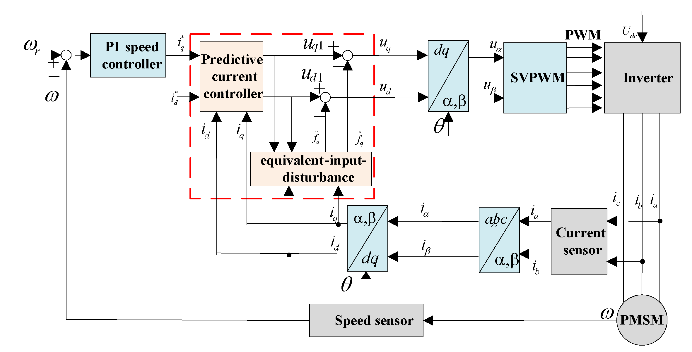
3. Current Control Scheme for PMSM

The control structure of PMSM control system with the proposed current control method is shown in Figure 1. The controller uses a cascade control structure including an out speed loop and two inner current loops. Here, the PI controller is used in the speed loop to realize the tracking control of motor speed, thus the q-axes reference current i q * = k p ( ω r ω ) + k i 0 t ( ω r ω ) d t , where ω r is the reference speed. The reference current i d * is set to be zero. In this paper, a novel deadbeat predictive controller with equivalent-input-disturbance is used to solve the current control problem.

3.1. Deadbeat Predictive Current Controller for Pmsm

The model of the system (1) can be expressed as
d i d d t d i q d t = R s L d 0 0 R s L q i d i q + 1 L d 0 0 1 L q u d u q + 1 L d 0 0 1 L q f d f q
where f d = n p ω L q i q + ξ d and f q = n p ω L d i d n p ω Φ + ξ q are considered as the lump disturbance, which include the disturbance and the back-electromotive force.
In the condition of ignoring the lump disturbance, the predictive model of (4) is expressed as a discrete-time form:
i d ( k + 1 ) i q ( k + 1 ) = 1 R s L d T s 0 0 1 R s L q T s i d ( k ) i q ( k ) + T s L d 0 0 T s L q u d 1 ( k ) u q 1 ( k )
where T s is the sample time. u d 1 and u q 1 are the control input without considering the lump disturbance.
Define the state variable as x ( k ) = x 1 ( k ) x 2 ( k ) T = i d ( k ) i q ( k ) T , the input variable as u 1 ( k ) = u d 1 ( k ) u q 1 ( k ) T , and the output variable as y ( k ) = y 1 ( k ) y 2 ( k ) T = i d ( k ) i q ( k ) T .
The premise of deadbeat predictive current control is that the actual current I ( k ) is sampled at the beginning of the k t h carrier cycle, and the predicted value of current deviation vector Δ I ( k ) is obtained, then the reference voltage output is calculated [22]. For achieving the current control, the required input voltage u 1 ( k ) at the current time can be calculated through the sample current x ( k ) at k T and x ( k + 1 ) at ( k + 1 ) T . However, in a practical control system, the reference voltage u 1 ( k ) is not added to the inverter immediately at k T , and it is carried out at ( k + 1 ) T . Therefore, the sample current x ( k + 1 ) just reaches the reference current x * ( k ) = i d * i q * T at k T .
Take the reference current x * ( k ) as the predictive current value at ( k + 1 ) T , thus i d ( k + 1 ) i q ( k + 1 ) = i d * i q * . According to Equation (5), the following can be calculated.
u d 1 ( k ) u q 1 ( k ) = T s L d 0 0 T s L q 1 i d * ( k ) i q * ( k ) 1 R s L d T s 0 0 1 R s L q T s i d ( k ) i q ( k )
The control laws in (6) are the reference dq-axes voltage based on deadbeat predictive control. The designed controller can solve the deadbeat control problem in general without additional means of support, but the lump disturbance is ignored, and the current control results will be affected in the face of the strong disturbance.

3.2. Disturbance Observer Based on EID

To suppress the lump disturbance in the system and improve the robustness, an equivalent- input-disturbance approach combined with the deadbeat predictive controller is studied. EID approach is a simple disturbance attenuation method and it can be easily implemented in the digital controller because it does not require an inverse model of the plant or prior information on the disturbance. Usually, an EID-based control system includes a state observer, an EID estimator, and state feedback [29]. The structural diagram of EID is shown in Figure 2. Thus, the deadbeat predictive controller can be seen as the state feedback.
Firstly, according to (4), the model can be described as
x ˙ = A x + B u + B d y = c x
where A = R s L d 0 0 R s L q , B = 1 L d 0 0 1 L q , C = 1 0 0 1 , u = u d u q T and d = f d f q T .
The system is controllable and observable, and it has no zeros on the imaginary axis, which guarantees the internal stability of the motor system and allows the speed to track the reference value [31]. Assume the distubance d satisfies d < d M , where d M is an unknown positive real number.
The EID is estimated by making the best use of the state observer of the system. A full-order observer is used to estimate the EID, then a state observer is defined as
x ^ ˙ = A x ^ + B u 1 + L [ y y ^ ] y ^ = c x ^
where u 1 = u d 1 u q 1 T , L is the observer gain, and x ^ is the reconstructed state of x.
According to the literatures [29,30], the estimator of EID is derived as
d ^ = B 1 L C [ x x ^ ] + u 1 u
where B 1 = ( B T B ) 1 B T .
As the output y contains a measurement noise, to depress the noise of the measured output current, a low-pass filter is used in the estimator of EID, thus d F = F ( s ) d ^ , F ( s ) = B F s + A F is the low-pass filter.
Combing the deadbeat controller and the EID estimator, the final current controller of PMSM control system can be given as
u = u 1 d F
In the paper, the model of PMSM is represented as the linear model, which is shown in Equation (7). The stability of the motor drive system can be broken down into two independent parts: state feedback and the observer. First, the state feedback is designed by the deadbeat predictive control method. Then, according to the Theorem 1 in the work by the authors of [31], the conditions are satisfied for the motor system. Thus, the stability of the control system can be guaranteed.
Meanwhile, the following simulation and experiment in different conditions prove that the motor can run steadily.

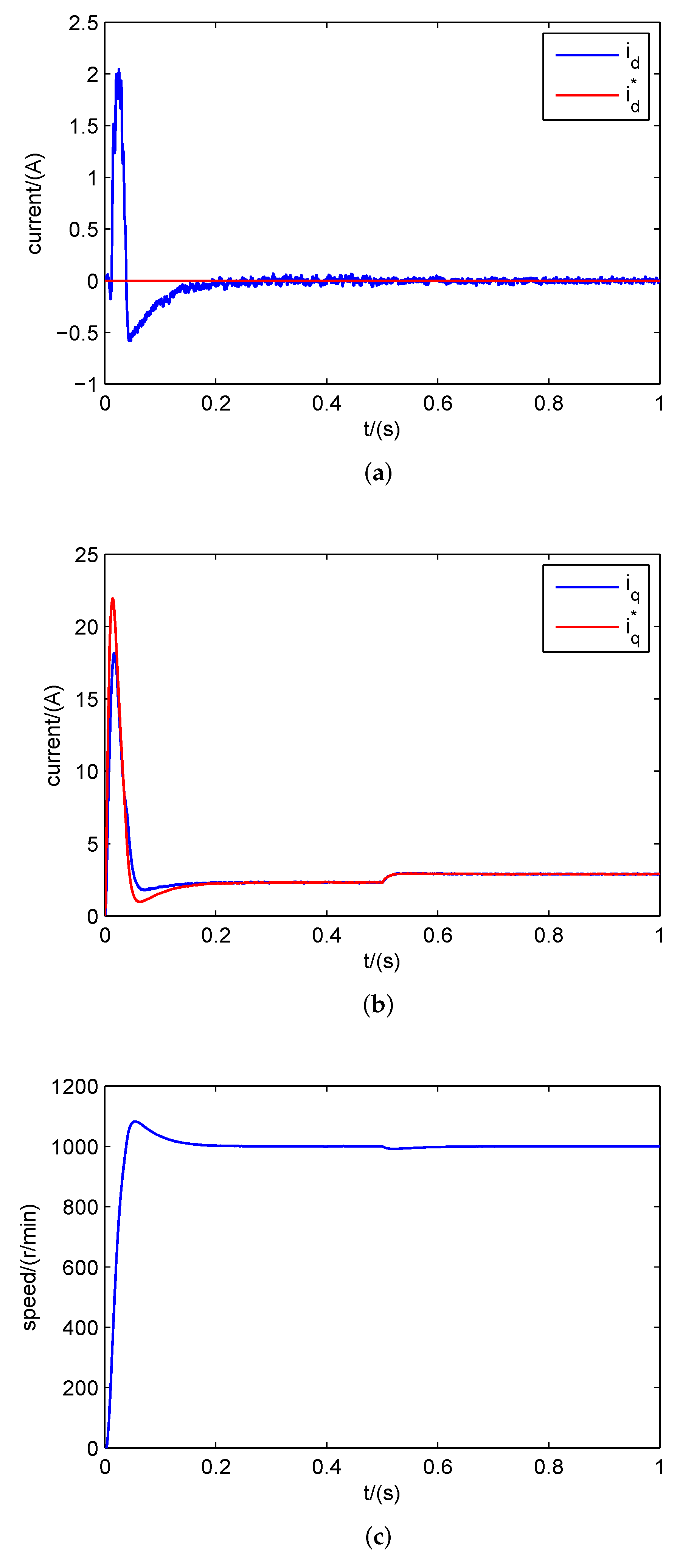
4. Simulation and Experiment

The proposed current control method with deadbeat predictive control and equivalent input disturbance approach is implemented in simulation and dSPACE based experiment. The motor parameters used in the simulation and experiment are given in Table 1.

4.1. Simulation and Analysis

The simulation is completed in the speed control system of PMSM. The double closed-loop vector control method is used for the speed and current control, the out loop is the speed loop, and the inner loop is the current loop. The motor reference speed is given as ω r = 1000 r/min, and the load torque 1 N·m is added on the motor. The PI controller is adopted in the speed loop. In order to verify the merit of the proposed method, in the current loop, both PI current controller and proposed current control method have been completed, respectively. The parameters of speed loop are consistent with each other in both methods. In addition, to validate the current tracking performance of the proposed control method while the motor has parameter perturbation, the values of rotor–flux linkage, armature resistance, and dq-axes inductance are changed to 80%, 200%, and 150% of the normal values at t = 0.5 s, respectively. Figure 3 shows the motor response waveform based on PI control. Figure 3a,b shows the dq-axes current waveform. The motor speed response curve is shown in Figure 3c. The simulation results based on the proposed current control method are shown in Figure 4.
As shown in Figure 3 and Figure 4, compared with the PI control, the proposed predictive current control method has better current control performance with a faster current response and smaller current fluctuation. When the motor parameters are changed, the results show that the parameter variations has little influence to the current control performance, and the proposed method in this paper still has precise current tracking and antidisturbance performance. Meanwhile, the control system has the good speed tracking performance.
To verify the effectiveness of the proposed method under the change of reference current, the d-axes reference current is changed from 0 to −1A at t = 0.5 s, and Figure 5 shows the current and speed response waveform. As shown in the figures, the dq-axes current varies with the change of the reference current, and the controller also good current tracking performance. Meanwhile, the motor speed has a small fluctuation, and it can be stable for a short period of time.
In addition, to test the performance of the controller with load disturbance, the reference speed is given as 1000 r/min, the load torque is changed from 1 N·m to 2 N·m at t = 0.5 s, and other parameters are fixed. The results are show in Figure 6. The figures reveal that with the increase of load torque, the q-axis current increases quickly to produce the same electromagnetic torque. Although the reference current has a variation with the change of load torque, the motor current can still track the reference value, and the robustness can be maintained in steady-state.
To better validate the advantage of the proposed current control method under parameter disturbance, three different comparative methods—PI current control, deadbeat predictive control without equivalent input disturbance approach, and the proposed method—have been used in the current loop controller of the drive system, respectively. The reference speed is also given as 1000 r/min, but the motor parameters are changed when the motor is started. The results based on three current control methods are shown in Figure 7, Figure 8 and Figure 9. The speed loop has the same parameters as the PI control method.
The results show that compared to the PI control, the proposed method has the smaller current fluctuation and the shorter settling time when the motor starts. Both methods have strong robustness for the parameter of disturbance. Although the deadbeat predictive current controller has the fast response, there is an obvious error between the output current and the reference values, and the dq-axes current cannot track the reference values accurately. The above results verify that the proposed method has better current control performance.

4.2. Experiment and Analysis

The experiment is implemented on a dSPACE-based PMSM control platform, as shown in Figure 10. The system includes an interior PMSM, a dynamometer, a converter based on IPM, and the dSPACE MicroAutoBox as the control board. MicroAutoBox is a rapid prototyping (RCP) system, and it is ideally suited as hardware for prototyping in the motor drive system. The current is measured by the Hall sensor and it is turned to the digital signal through ACMC module. The experiment is completed on a speed control system of PMSM based on a doubled closed-loop structure. The deadbeat predictive controller with EID is used in the current loop control. The parameters of the PMSM are given in Table 1. The sample time is chosen as T s = 0.1 ms. The observer gain L is the main parameter to be adjusted in the controller. The larger the gain is, the faster the observer converges. However, in general, the gain, L, cannot be too large. Otherwise, the system will be too sensitive to the interference signal and the stability of the system will decrease. So the observer gain of L = 100 0 0 100 is chosen in the controller. The low-pass filter is chosen as F ( s ) = 200 s + 200 .
First, the motor starting speed is given as 1000 r/min. When the motor is stable, the reference speed is changed from 1000 r/min to 1500 r/min, and the experimental results are shown in Figure 11 and Figure 12, which include the dq-axes current and speed response waveforms. As seen from Figure 11 and Figure 12, when the motor is starting, the large starting current is produced, and the dq-axes current reaches to the reference current value soon. The designed current controller has the good tracking performance. The practical output current has a small fluctuation, which may be caused by the current harmonic, but the tracking performance is not affected. The motor speed can also arrive at the given value quickly.
To further evaluate the performance of the proposed control method, the q-axe reference current is changed in the experiment. When the motor is working in 1000 r/min, the load torque disturbance is added to the motor at t = 1 s, and the experimental results are shown in Figure 13. We can see that the q-axes current changes with the increase of load torque, and it can converge to its reference value quickly. In this process, the d-axes current is not affected by the load disturbance, can stay at zero, and the robustness still can be maintained.
To further verify the robustness of the proposed method with the parameters perturbation, the controller parameters are set mismatched with the real motor parameters. In comparison with the real values in the controller, the dq-axes inductances are set as two times of the rated values in the controller. The corresponding results are shown in Figure 14. Although the parameters are not consistent between the current controller and the motor, there is no large difference in the actual output current and the reference current. The experimental results prove the designed controller has excellent robustness for the disturbance.

5. Conclusions

In this paper, a novel current control method based on deadbeat predictive control and equivalent- input-disturbance theory has been proposed for PMSM drive. With the designed deadbeat controller, the current stabilizing control is achieved. According to the disturbance in the PMSM, we have designed an equivalent-input-disturbance estimator for the feed-forward compensation, and the robustness can be maintained under the disturbance. The simulation and experiment results have proved that the controller has good current tracking performance in different conditions. Meanwhile, the designed current controller is also suitable for torque control system of PMSM.

Author Contributions

Conceptualization, X.L.; methodology, X.L. and Q.Z.; software, X.L.; validation, X.L. and Q.Z.; formal analysis, Q.Z.; investigation, X.L.; resources, X.L.; data curation, Q.Z.; writing—original draft preparation, X.L.; writing—review and editing, X.L. and Q.Z.; visualization, X.L.; supervision, X.L.; project administration, X.L. and Q.Z.; funding acquisition, X.L. and Q.Z.

Funding

This research was funded by the National Natural Science Foundation of China under Grant 61703222, and in part by the China Postdoctoral Science Foundation under Grant 2018M632622.

Conflicts of Interest

The authors declare no conflict of interest.

References

  1. Liu, X.; Yu, H.; Yu, J.; Zhao, L. Combined speed and current terminal sliding mode control with nonlinear disturbance observer for PMSM drive. IEEE Access 2018, 6, 29594–29601. [Google Scholar] [CrossRef]
  2. Ren, J.; Ye, Y.; Xu, G.; Zhao, Q. Uncertainty-and-disturbance-estimator-based current control scheme for PMSM drives with a simple parameter tuning algorithm. IEEE Trans. Ind. Electron. 2017, 32, 5712–5722. [Google Scholar]
  3. Qian, J.; Ji, C.; Pan, N.; Wu, J. Improved sliding mode control for permanent magnet synchronous motor speed regulation system. Appl. Sci. 2018, 8, 2491. [Google Scholar] [CrossRef]
  4. Merabet, A.; Tanvir, A.; Beddek, K. Torque and state estimation for real-time implementation of multivariable control in sensorless induction motor drives. IET Electr. Power Appl. 2017, 11, 653–663. [Google Scholar] [CrossRef]
  5. Yang, X.; Yu, J.; Wang, Q.; Zhao, L. Adaptive fuzzy finite-time command filtered tracking control for permanent magnet synchronous motors. Neurocomputing 2019, 337, 110–119. [Google Scholar] [CrossRef]
  6. He, L.; Wang, F.; Wang, J.; Rodriguez, J. Zynq implemented lunenberger disturbance observer based predictive control scheme for PMSM drives. IEEE Trans. Power Electron. 2019. [Google Scholar] [CrossRef]
  7. Liu, X.; Yu, H.; Yu, J.; Zhao, Y. A novel speed control method based on port-controlled hamiltonian and disturbance observer for PMSM drives. IEEE Access 2019, 7, 111115–111123. [Google Scholar] [CrossRef]
  8. Merabet, A.; Labib, L.; Ghias, A. Robust model predictive control for photovoltaic inverter system with grid fault ride-through capability. IEEE Trans. Smart Grid 2018, 9, 5699–5709. [Google Scholar] [CrossRef]
  9. Kouro, S.; Cortes, P.; Vargas, C.; Ammann, U. Model predictive control—a simple and powerful method to control power converters. IEEE Trans. Ind. Electron. 2008, 56, 1826–1838. [Google Scholar] [CrossRef]
  10. Turker, T.; Buyukkeles, U.; Bakan, A. A robust predictive current controller for PMSM drives. IEEE Trans. Ind. Electron. 2016, 63, 3906–3914. [Google Scholar] [CrossRef]
  11. Guo, X.; Du, S.; Li, Z.; Chen, F. Analysis of current predictive control algorithm for permanent magnet synchronous motor based on three-level inverters. IEEE Access 2019, 7, 87750–87759. [Google Scholar] [CrossRef]
  12. Chai, S.; Wang, L.; Rogers, E. A cascade MPC control structure for a PMSM with speed ripple minimization. IEEE Trans. Ind. Electron. 2013, 60, 2978–2987. [Google Scholar] [CrossRef]
  13. Zhang, G.; Chen, C.; Gu, X.; Zhang, Z. An improved model predictive torque control for a two-level inverter fed interior permanent magnet synchronous motor. Electronics 2019, 8, 769. [Google Scholar] [CrossRef]
  14. Zhang, X.; Zhang, L.; Zhang, Y. Model predictive current control for PMSM drives with parameter robustness improvement. IEEE Trans. Power Electron. 2019, 34, 1645–1657. [Google Scholar] [CrossRef]
  15. Luo, Y.; Liu, C. A simplified model predictive control for a dual three-phase PMSM with reduced harmonic currents. IEEE Trans. Ind. Electron. 2018, 65, 9079–9089. [Google Scholar] [CrossRef]
  16. Zhang, X.; Hou, B.; Mei, Y. Deadbeat predictive current control of permanent magnet synchronous motors with stator current and disturbance observer. IEEE Trans. Power Electron. 2016, 32, 3818–3834. [Google Scholar] [CrossRef]
  17. Chen, W.; Yang, J.; Guo, L.; Li, S. Disturbance-observer-based control and related methods-an overriew. IEEE Trans. Ind. Electron. 2016, 63, 1083–1095. [Google Scholar] [CrossRef]
  18. Yang, J.; Chen, W.; Li, S.; Guo, L. Disturbance/uncertainty estimation and attenuation techniques in PMSM drives—A survey. IEEE Trans. Ind. Electron. 2017, 64, 3273–3285. [Google Scholar] [CrossRef]
  19. Sun, Z.; Guo, T.; Yan, Y.; Wang, X. A composite current-constrained control for permanent magnet synchronous motor with time-varying disturbance. Adv. Mech. Eng. 2017, 9, 1–13. [Google Scholar] [CrossRef]
  20. Liu, X.; Zhang, C.; Li, K.; Zhang, Q. Speed control for permanent magnet synchronous motor based on an improved extended state observer. ISA Trans. 2017, 71, 542–552. [Google Scholar] [CrossRef]
  21. Turker, T.; Yanik, G.; Buyukkeles, U.; Mese, E. A discrete-time nonlinear robust controller for current regulation in PMSM drives. J. Electr. Eng. Technol. 2017, 12, 1921–1931. [Google Scholar]
  22. Niu, L.; Yang, M.; Wang, G.; Xu, D. Research on the robust current control algorithm of permanent magnet synchronous motor based on deadbeat control principle. Proc. CSCC 2012, 33, 78–85. [Google Scholar]
  23. Wang, W.; Xiao, X. Research on predictive control for PMSM based on online parameter identification. In Proceedings of the 38th IEEE Industrial Electronics Society Annual Conference, Glendale, AZ, USA, 7–10 November 2010; pp. 1982–1986. [Google Scholar]
  24. Jiang, Y.; Xu, W.; Mu, C.; Liu, Y. Improved deadbeat predictive current control combined sliding mode strategy for PMSM drive system. IEEE Trans. Veh. Technol. 2018, 67, 251–263. [Google Scholar] [CrossRef]
  25. Mohamed, Y.; EI-Saadany, E. Robust high bandwidth discrete-time predictive current control with predictive internal model-a unified approach for voltage-source PWM converters. IEEE Trans. Ind. Electron. 2008, 23, 126–136. [Google Scholar] [CrossRef]
  26. Yang, M.; Liang, X.; Long, J.; Xu, D. Flux immunity robust predictive current control with incremental model and extended state observer for PMSM drive. IEEE Trans. Power Electron. 2017, 23, 9267–9279. [Google Scholar] [CrossRef]
  27. Yang, R.; Wang, M.; Li, L.; Zhang, C. Robust predictive current control with variable-gain adaptive disturbance observer for PMLSM. IEEE Access 2018, 6, 13158–13169. [Google Scholar] [CrossRef]
  28. Du, Y.; Cao, W.; Wu, M.; She, J. Disturbance rejection and control system design using improved equivalent- input-disturbance approach. IEEE Trans. Ind. Electron. 2019. [Google Scholar] [CrossRef]
  29. Liu, R.; Liu, G.; Wu, M. Robust disturbance rejection based on equivalent-input-disturbance approach. IET Control Theory Appl. 2013, 7, 1261–1268. [Google Scholar] [CrossRef]
  30. Gao, F.; Wu, M.; She, J. Disturbance rejection in nonlinear systems based on equivalent-input-disturbance approach. Appl. Math. Comput. 2016, 282, 244–253. [Google Scholar] [CrossRef]
  31. She, J.; Fang, M.; Ohyama, Y. Improving disturbance-rejection performance based on an Equivalent-Input- Disturbance approach. IEEE Trans. Ind. Electron. 2008, 55, 380–389. [Google Scholar] [CrossRef]
Figure 1. Block diagram of permanent magnet synchronous motor (PMSM) control system.
Electronics 08 01034 g001
Figure 2. Structural diagram of equivalent-input-disturbance (EID).
Electronics 08 01034 g002
Figure 3. Simulation results with proportional plus integral (PI) control: (a) d-axes current; (b) q-axes current; and (c) speed response.
Electronics 08 01034 g003
Figure 4. Simulation results with the proposed method: (a) d-axes current; (b) q-axes current; and (c) speed response.
Electronics 08 01034 g004
Figure 5. Simulation results with the proposed method when i d * is changed: (a) d-axes current, (b) q-axes current, and (c) speed response.
Electronics 08 01034 g005
Figure 6. Simulation results with the proposed method when the load torque changed: (a) d-axes current, (b) q-axes current, and (c) speed response.
Electronics 08 01034 g006
Figure 7. Simulation results with PI control method under the parameter disturbance: (a) d-axes current and (b) q-axes current.
Electronics 08 01034 g007
Figure 8. Simulation results with deadbeat control method under the parameter disturbance: (a) d-axes current and (b) q-axes current.
Electronics 08 01034 g008aElectronics 08 01034 g008b
Figure 9. Simulation results with the proposed method under the parameter disturbance: (a) d-axes current and (b) q-axes current.
Electronics 08 01034 g009
Figure 10. Experimental platform of PMSM drive system.
Electronics 08 01034 g010
Figure 11. Experimental results with the proposed method: (a) d-axes current; (b) q-axes current; and (c) speed response.
Electronics 08 01034 g011
Figure 12. Experimental results with the increase of reference speed: (a) d-axes current; (b) q-axes current; and (c) speed response.
Electronics 08 01034 g012
Figure 13. Experimental results with load disturbance: (a) d-axes current, (b) q-axes current, and (c) speed response.
Electronics 08 01034 g013
Figure 14. Experimental results with parameter variations: (a) d-axes current, (b) q-axes current, and (c) speed response.
Electronics 08 01034 g014
Table 1. Parameters of PMSM.
DescriptionValueUnit
rated speed3000r/min
rated torque2.3N·m
resistance4.8 Ω
d-axes inductance19.5mH
q-axes inductance27.5mH
rotor flux0.15Wb

