Review

Planar Textile Off-Body Communication Antennas: A Survey

by
Ruben Del-Rio-Ruiz
*,
Juan-Manuel Lopez-Garde
and
Jon Legarda
Faculty of Engineering, University of Deusto, Avda. Universidades, 24, 48007 Bilbao, Spain
*
Author to whom correspondence should be addressed.
Electronics 2019, 8(6), 714; https://doi.org/10.3390/electronics8060714
Submission received: 31 May 2019 / Revised: 18 June 2019 / Accepted: 20 June 2019 / Published: 24 June 2019
(This article belongs to the Special Issue Intelligent Antennas)

Abstract

:
Fully textile smart wearables will be the result of the complete integration and miniaturization of electronics and textile materials. Off-body communications are key for connecting smart wearables with external devices, even for wireless power transfer or energy harvesting. They need to fulfill specific electromagnetic (EM) (impedance bandwidth (BW), gain, efficiency, and front to back radiation (FTBR)) and mechanical (bending, crumpling, compression, washing and ironing) requirements so that the smart wearable device provides the required performance. Therefore, textile and flexible antennas require a proper trade-off between materials, antenna topologies, construction techniques, and EM and mechanical performances. This review shows the latest research works for textile and flexible planar, fully grounded antennas for off-body communications, providing a novel design guide that relates key antenna performance parameters versus topologies, feeding techniques, conductive and dielectric textile materials, as well as the behavior under diverse measurement conditions.

1. Introduction

The convergence of electronics and conductive textiles (e-textiles) to create smart wearable devices remains challenging in several application areas such as medical, sport, art, military, or aerospace. They will be capable of sensing data, controlling actuators, communicating with external devices, and even being recharged wirelessly. Miniaturization and integration of electronics into smart textiles are key for this revolution. Nevertheless, the performance of certain components like sensors [1,2], energy harvesters [3,4,5], or antennas is dependent on their dimensions and cannot be miniaturized.
Off-body communication antennas are used in smart textile devices to communicate with other external devices. The topology and materials of these antennas play a key role in the smart textile devices’ efficiency, manufacturing cost, and mechanical performance (bending, crumpling, washing, and ironing). There have been reported many textile antenna topologies, but off-body communication antennas require the minimization of front-to-back radiation (FTBR) levels (to avoid the negative effects of the human body, and the degradation of the antennas’ performance), while having the required impedance bandwidth (BW), high radiation efficiency, and low antenna volume. On the other hand, the inherent proximity of the human body to the antenna gives special concern to the wearers’ health safety, and therefore the specific absorption rate (SAR) [6,7] is also a key aspect to take into consideration.
Antennas with full-ground planes are good candidates to enhance the FTBR and SAR values for body-worn applications. Recent literature on fully-grounded planar topology antennas constructed with non-textile materials show promising electromagnetic (EM) performances in terms of measured BW, maximum peak gain, radiation efficiency, and FTBR [8,9,10,11,12,13,14,15,16,17]. They are normally based on well characterized dielectric and conductive materials, like Rogers Duroid 5880 [8,9,10,14,18,19,20,21,22,23,24,25], Rogers 4003 [12], Rogers 3003 [14], and F4B [16] and FR4 Microwave [26,27,28,29], which lead to consistent results between simulations and measurements. The thinness of the substrates used (between 0.5 mm and 2 mm) [8,10,12,13,16,18,19,20,24,25,26,28,30] offers good BW and radiation efficiencies, giving some clues about their potential for textile applications. They also allow for a plethora of design alternatives to improve the EM performances, normally based on three patch shapes, like rectangular [8,9,11,12,13,15,18,20,22,24,25,26,29,30], circular [21,23,31], and square [14,19], combined with different slotted patch configurations like linear [8,12,16,19,20,26,28,30], meandered [18], ramp [18], circular-ring [21], complex [17,22], L-shaped [29], and U-shaped [24]. Feeding techniques are also relevant when they are used for textile applications—coaxial fed [11,12,14,16,17,21,23,24,25,26,28,31], microstrip line fed [9,10,22,30], microstrip inset line fed [8,9,19,20], aperture-coupled fed [13], and L-shaped line fed [15] antennas. Finally, antennas for single-band [8,9,10,11,12,13,14,15,16,17,18,19,20,23,24,25,26,28,30,31], dual-band [29], and reconfigurable bands [21,22,25] have been reported, which is sometimes also also desirable in textile applications.
This is the reason why this survey is focused on analyzing textile antennas with a full-ground plane for off-body communications, combining the potential of fully grounded topologies with the challenges of textile materials. These antennas can be thin, lightweight, robust, and easily manufactured. They can even be used for energy harvesting as the available space over the textile surface is high. But greater dimensions require solutions based on textile materials that guarantee comfortable and aesthetically acceptable designs and robust performance against bending, crumpling, washing, and ironing. Moreover, EM characteristics of textile materials are crucial for good antenna performance. For instance, the permittivity, loss tangent, and thickness of the substrates are main factors for good BW and radiation efficiency of the antennas.
The structure of this survey is as follows: Section 2 presents an analysis on the latest literature on planar off-body textile antenna designs and their EM performance on ideal scenarios (flat surface and free-space), describing their feeding techniques and antenna topologies. Section 3 describes the latest reported textile antenna construction techniques, and their main dielectric and conductive materials. Section 4 discusses the EM performance of textile antennas under diverse conditions (on-body, bending, crumpling, compression, humidity). Finally, Section 5 gives the main conclusions and future work.

2. Antenna Designs and Performance

Fully grounded planar antenna topologies have been broadly used for off-body communications because of their high body isolation, low profile, robustness, ease of fabrication, and low cost [32,33]. Textile materials add a better bending performance, lower permittivity, lighter weight, and lower costs, which—combined with fully grounded planar topologies—make them ideal for off-body communications. Nevertheless, the main drawback of these topologies is their usually narrow BW [34,35,36]. The research within this type of textile antennas has recently been focused on the enhancement of the BW with different feeding techniques and design topologies. Many solutions have been proposed in the literature: (I) Increasing substrate thickness [37,38,39], (II) designing complex radiator patches [7,40,41], (III) adding slots to the radiator patch [6,37,42], (IV) including parasitic elements [34,40,43], (V) inserting Artificial Magnetic Conductors (AMC) [6,36,43], (VI) using Substrate Integrated Waveguide (SIW) topologies [44,45,46], using Planar Inverted F-Antennas (PIFA) topologies [42,47,48], or (VII) using different feeding techniques [32,42,49].
AMC planes are made of metamaterial emulating a magnetic conductor over a limited frequency band dependent on its design. They are implemented on planar antennas, forming a reflector and reducing the FTBR, they can be designed for wide-band or dual-band applications, and they can replace the usual ground plane [6,36,43,50]. AMC planes consist of periodic structures (square [6], ring [43], cross [36], and complex [50]) in arrays (4 × 4 [6], 3 × 5 [43], 3 × 3 [36] and 2 × 2 [50]).
The addition of slots in the radiator patch modifies the current on the patch [6,45,47,51], leading to better antenna performance: (I) BW enhancement [6,36,43,44,47,52], (II) dual-band or multi-band resonant frequencies [44,51,52,53,54], (III) miniaturization of the overall antenna size [6,36,45,53], (IV) antenna frequency tuning [45,51,52,53,54,55], and (V) circular polarization [54].
This section analyzes and organizes the most recent literature reported on textile antenna designs and EM performance into four areas: (I) The feeding techniques, (II) antenna topologies used in fully grounded planar antennas for off-body communications, (III) their main EM parameters in ideal conditions (flat surface and free-space), and (IV) some final conclusions regarding a new figure of merit that is proposed.
Note that figures shown in this section have been designed with rectangular radiator patches, nevertheless circular [52,54,56,57], square [6,34,39,58], and other complex shapes [7,36,40,41,43,44,48] have been found in the latest literature.

2.1. Feeding Techniques

2.1.1. Coaxially Fed Antennas

The coaxial probe feeding technique is well implemented in off-body communications textile antennas. The basic scheme is shown in Figure 1a. The outer conductor of the coaxial probe is connected to the ground plane, and the inner connector to the radiator patch. The coaxial probe introduces an inductance, which depends on its length and is determined by the substrate’s thickness of the antenna [59]. Their fabrication at lab scale is simple, their compactness in terms of the overall volume is good, and their impedance matching is easily obtained with capacitive coupling radiator patches [7] or adjusting the position of the feeding point [41,44,52,53,55]. The main BW enhancement techniques that do not change the antenna topology are based on slots in the radiator patch [6,37,44,45,47,48,50,52,53,55] or on parasitic elements close to the radiator patch [7,36,43]. This feeding technique is not ideal for real textile applications that are expected to be flexible and comfortable, since the rigid coaxial probe is part of the antenna and can not be removed after antenna testing.

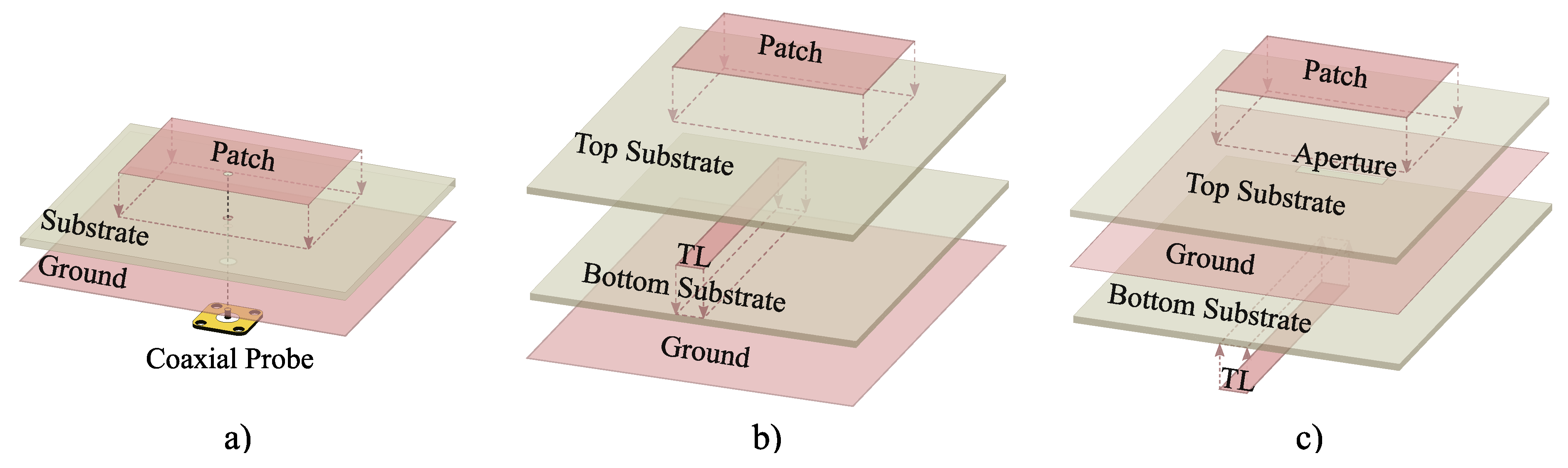
2.1.2. Multilayer Feeding Techniques

Ideally, multilayer feeding techniques provide a better textile performance than coaxial probes, since there is no need for rigid pins going through different layers, and the connector can be removed after the antenna evaluation is performed. There are two main multilayer feeding techniques, based on electromagnetic (proximity) and aperture coupling. Their basic construction schemes are shown in Figure 1b,c, respectively. The former is composed (from bottom to top) of a ground layer, bottom substrate, transmission line (TL), top substrate, and radiator patch. The latter is composed (from bottom to top) of a TL, bottom substrate, ground layer with an aperture, top substrate, and radiator patch.
The proximity coupled microstrip antenna is excited from the TL and electromagnetically coupled through the top substrate to the radiator patch. The TL is inserted between two substrate layers, the ground plane and partially the radiator patch, where any radiation from the feeding line is shielded and potentially re-radiated by the patch, leading to a good cross-polarization [60] and a good body isolation. On the other hand, aperture-coupled fed microstrip antennas [61,62] are not ideal for off-body communications since the TL is not isolated from the body. This creates a non-desired energy absorption and modifies the radiation signal pattern due to the high permittivity and losses of human skin tissue.
Multilayer microstrip feeding techniques increase the BW of the antennas, they are robust to bending, but the manufacturing process needs to be more precise due to the required multilayer alignment [32,40,49,63]. According to the latest literature, there have not been any designs found with parasitic elements or slots in the radiator patch.

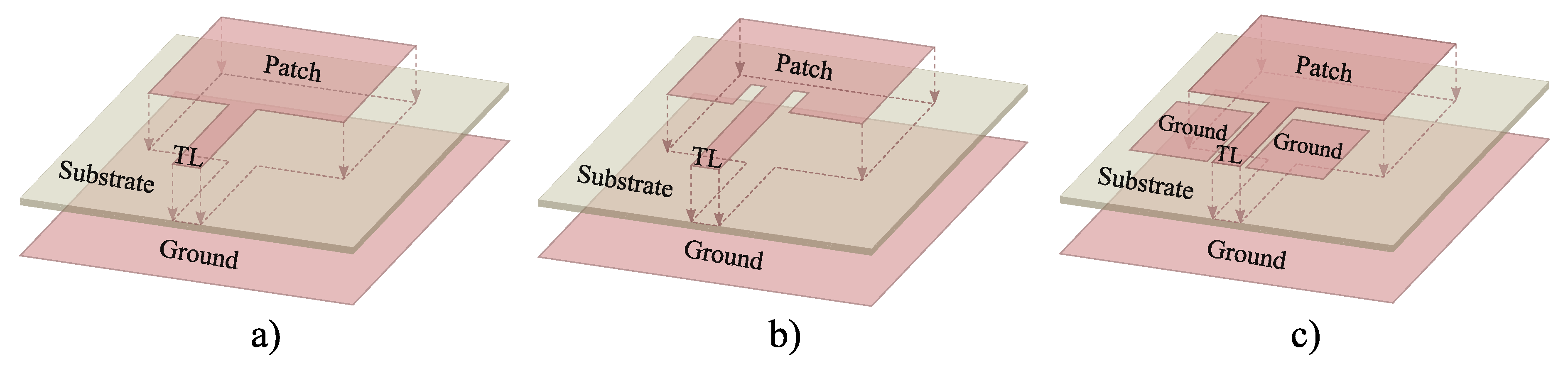
2.1.3. Microstrip Line Feeding Techniques

The microstrip line feeding technique is also widely used for textile applications. It consists of a radiator patch with a TL, a dielectric substrate, and a ground plane, as illustrated in Figure 2a. They do not have any coaxial probe going through the layers or multilayer structures, which decreases the manufacturing complexity and improves the antenna’s flexibility. The impedance matching is made possible by modifying the width and length of the TL [64,65,66] or by creating an inset gap in the patch [33,67], as shown in Figure 2b. With this feeding technique, array antennas can be easily implemented—modifying the TL length and width to obtain the required input impedance for each antenna element [32,49,68]. On the other hand, the increase of TL length also increases the losses, the overall size of the antenna, and the impedance matching complexity. According to the latest literature, slotted radiator patches fed with a TL have also been proposed [51,69].

2.1.4. Coplanar Waveguide Fed Antennas

The coplanar waveguide (CPW) fully grounded feeding technique is based on the microstrip line feeding technique, but with a truncated ground plane close to the TL [40,70,71]. Two equal planar ground planes are placed symmetrically on each side of the CPW line, as shown in Figure 2c. The impedance matching of the CPW feeding technique is achieved by optimizing the width of the TL and the gap between the TL and ground planes. This feeding technique is designed on three layer antenna structures (ground, substrate, and radiator patch), but multilayer antennas have also been used [40].

2.2. Antenna Topologies

There are three main planar antenna topologies for textile off-body communications—the microstrip antenna, the planar inverted F-antenna (PIFA), and the substrate integrated waveguide (SIW) antenna. They are shown in Figure 3, and the coaxial feeding technique has been used for sake of visual simplicity. Some general characteristics of these topologies are their light weight, their stable EM performance under bending conditions, their multi-band performance, and their flexibility to choose between linear or circular polarization.

2.2.1. Microstrip Antenna

The microstrip antenna, as shown in Figure 3a consists of a radiator patch, a dielectric substrate, a ground plane, and a feeding point that can be implemented with different techniques. The radiator patch dimensions (width ( W p ) , length ( L p ) , and thickness ( h ) ) determine the resonant frequency, BW, and efficiency of the microstrip antenna. The shape of the radiator patch (rectangular [32,33,35,37,42,49,50,72,73], circular [52,54,56,57], square [6,34,39,58], and others [7,36,40,41,42,43]) combined with the feeding technique (type, number of feeds, and their positions) determines the number of frequency bands, polarization, BW, and gain of the antenna.
Several BW enhancement techniques have been proposed for microstrip antenna topologies: (I) The modification of the patch creating complex designs to combine different resonant frequency bands [7,36,41,43], (II) the insertion of slots in the radiator patch [6,36,42,50,52,69], (III) the addition of parasitic elements to the radiator patch layer [7,36,40,42], and (IV) the modification of the feeding technique [34,40,42,49,63,74].

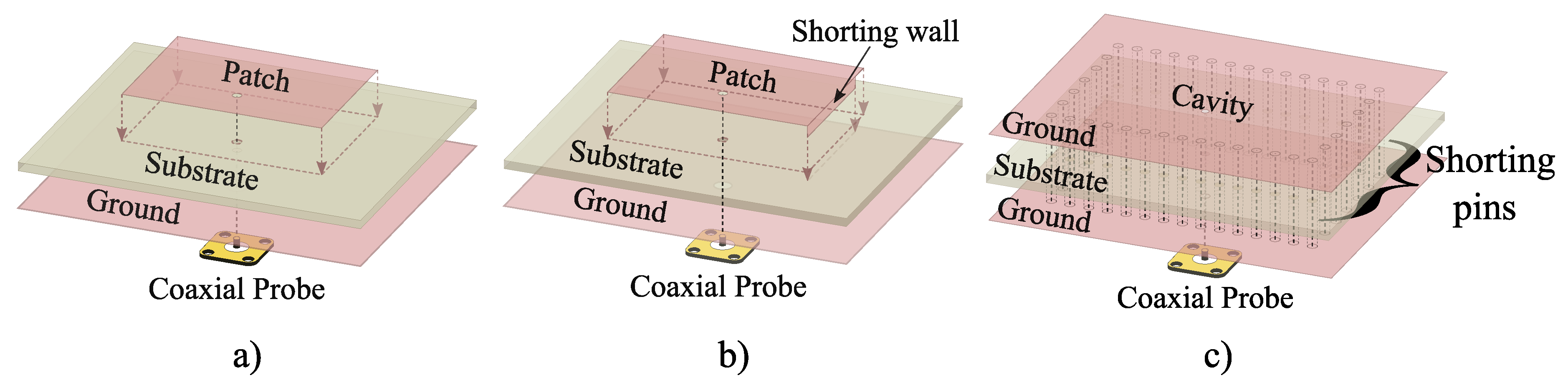
2.2.2. Planar Inverted F-Antenna

The PIFA antenna is an evolution of the microstrip antenna. It consists of a radiator patch, a dielectric substrate, a ground plane, a shorting wall, and a feeding probe, as shown in Figure 3b [42,47,48]. The shorting wall design and location, the feed line position, the thickness of the substrate, and the ground plane size are significant PIFA parameters [47] in order to improve the impedance BW and the dual–multi band performance compared to conventional microstrip antennas.
The main impedance BW enhancement techniques proposed for PIFA topologies are the insertion of slots in the radiator patch [47,48]. The utilization of other feeding techniques is not an option, and the addition of parasitic elements or the design of complex radiator patches have not been found in the recent literature for PIFA textile off-body communication antennas.

2.2.3. Substrate Integrated Waveguide Antenna

The SIW antenna could be considered as another evolution of the PIFA topologies. The single or specific shorted area between the ground and the radiator patch of PIFA topologies becomes periodic shorted pins of a closed shape, creating a resonant cavity, as shown in Figure 3c. The SIW structure consists of two conductive layers separated by a dielectric substrate, where the top conductive layer is usually fed with a coaxial probe. The advantages of these topologies are: (I) The increased isolation between antenna and wearer without the need for a large ground plane, (II) low-cost and low-loss implementation, (III) being compact and low profile [44], and (IV) their miniaturization possibilities by exploiting the symmetry of the field distribution of the resonant modes, like a half-mode or quarter-mode SIW [45]. The body isolation is significantly increased when compared to conventional microstrip antennas with larger ground planes and smaller dimensions [53].
The use of slots in the resonant cavity to enhance the impedance BW or to obtain dual band antennas has been reported in the recent literature [44,45,51,53,55]. Finally, note that most SIW topologies found in the literature for textile off-body communication antennas are fed with a coaxial probe, nevertheless, other feeding techniques have been found like the microstrip lines [51].

2.3. EM Antenna Performance

The main EM antenna performance parameters reported in this survey, as shown in Table 1 are: (I) −10 dB | S 11 | BW (%); (II) the maximum measured gain (dBi); (III) the total efficiency (%) of an antenna, as the ratio between the power radiated by the antenna and the power delivered to the antenna; (IV) the front To back radiation (FTBR) (dB), as the ratio between the power radiated in the main radiation lobe and the power radiated in the opposite direction; and (V) the Specific Absorption Rate (SAR) (W/kg), which is the absorbed RF energy by human tissue.
According to the latest literature: (I) The highest measured impedance BW are found on coaxially fed antennas with complex radiator patches, including parasitic elements and slots [7,36]; (II) the highest gain levels are reported on proximity fed rectangular and complex patch microstrip antennas, and on coaxially fed SIW topologies [7,42,55]; (III) the best measured antenna efficiencies are reported on SIW and PIFA topologies with slots [44,47,55]; (IV) the highest FTBR results are reported on proximity and coaxially fed microstrip patch antennas [32,42,45,48,57,73]; and (V) the lowest SAR values are found on coaxially fed slotted patch microstrip antennas [6,37,43,50,52,54,54].

2.4. Conclusions

Textile off-body communication antennas have a wide variety of design alternatives related to the feeding techniques (coaxial, proximity, aperture, microstrip line, microstrip inset line, and CPW) and antenna topologies (microstrip, PIFA, and SIW). Other alternative designs have been reported in the literature for BW enhancement, like the insertion of slots in the radiator patch or resonant cavities, or the addition of parasitic elements. Table 1 compiles the most relevant research works done so far in order to ease future designs of fully grounded textile antennas for off-body communications. A figure of merit has been used, considering the importance of having a high impedance BW, a high FTBR, and a low antenna volume. The measured efficiency of the antenna has not been taken into account, because of the lack of information in the reported literature. Nevertheless, it should be another feature to take into account in future surveys. The figure of merit has been calculated using (1), which has been normalized to 100 in Table 1.
k = B W ( % ) · F T B R ( d B ) v o l u m e ( λ 3 ) = f 2 f 1 f c · G f G b W · L · h ,
where f 1 , f 2 and f c are the minimum, maximum, and central frequencies of an antenna with return losses below −10 dB, respectively. G f and G b are the antenna gain at its peak (bore-sight) and its opposite direction, respectively.
The overall size ( λ ) of the antennas has been calculated using the lowest frequency of the −10 dB | S 11 | band. The overall volume of the antenna has been calculated (W·L·Thickness(h)) ( λ 3 ) . The measured gain, as shown in Table 1, represents the maximum gain in any given direction. Most FTBR values have been obtained from the measured radiation pattern graphs, since most of the reported literature just illustrate the graphs, but do not numerically describe the FTBR values. Most literature offers measured BW results, nevertheless, there is a lack of measured gain and efficiency parameters of the antennas. When a publication reports more than one relevant antenna implementation, each of them could be represented in separate rows in the table. All measured results illustrated in Table 1 have been obtained in free-space and flat surface scenarios. Antenna measurements under diverse conditions have been described in Section 4.
The figure of merit k shows that the combination of the highest BW, the highest FTBR, and the smallest antenna volume can be achieved using PIFA and proximity fed microstrip topologies. PIFA with slots and fed by a coaxial probe, reports excellent BW versus volume results. Proximity fed microstrip antennas, report excellent FTBR versus volume results. Note that a high FTBR in textile off-body communication antennas is key to obtain a low SAR and a low disturbance of the EM performance of the antenna due to the body proximity.
SIW topologies have reported a low k in this survey’s figure of merit, because their volume is large compared to their BW. Nevertheless, their radiation efficiency and FTBR are excellent for off-body communications. PIFA’s main drawbacks are their high substrate thickness and low FTBR, which makes this topology complex to embed in garments. Nevertheless, their wide BW and small overall surface ( W · L ) give them a good k value. Microstrip topologies have reported inconsistent results, nevertheless, proximity fed microstrip antennas show thin substrates and excellent FTBR results.

3. Antenna Construction Techniques

The right selection of feeding, antenna topology, or the BW enhancement techniques are the first steps to achieving the desired EM performance of a fully grounded planar antenna. However, in textile applications, the construction techniques and materials are also crucial, and are sometimes even more restrictive. A state of the art regarding materials for textile antennas can be found in [75]. Nevertheless, a brief enumeration of the latest reported dielectric and conductive materials is given in this survey. The main dielectric substrates are: (I) Felt [6,7,36,37,39,40,43,46,47,48,50,51,53,56,57,72], (II) foam [34,42,44,45,55], (III) denim [32,49,72,73], (IV) leather [41,54,58], (V) neoprene [58], and (VI) Polydimethylsiloxane (PDMS) [52]. The main conductive textile fabrics are: (I) Pure Copper Polyester Taffeta Fabric (PCPTF) [32,35,44,45,47,49,55,58], (II) silver-coated nylon ripstop fabric [42,52], (III) Nickel–copper polyester ripstop fabric [33,73], (IV) ShieldIt Super fabric [6,7,36,37,40,43,46,47,50,53,72], (V) Shieldex Zell [41,51,54,56,57], and (VI) Shieldex NoraDell [39]. Conductive threads have also been reported for PIFA and SIW antennas’ shorting vias and for fully embroidered antennas: (I) Metallic wires [37], (II) 92 ShieldEx [51,54,56], (III) Liberator 20 [39], and (IV) ShieldEX 117f17 1-2 ply [69].
This section introduces the state of the art of how the latest literature deals with (I) the attachment of RF connectors to the textile antennas, (II) the multilayer attachment, (III) alignment, and (IV) the different cutting techniques of the fabrics.
(1) The attachment of an RF connector is necessary to evaluate the EM performance of the antennas [37,76]. SubMiniature version A (SMA) straight RF connectors [7,40,42,45,46,47,52] and Hirose Ultra-small surface mount coaxial connector (U.FL) [34,55] have been used for antenna evaluations, according to the recent literature. SMA connectors are bulky and degrade the flexibility of the antenna [37,46], but have a pin which serves as a feed for the coaxial probe, decreasing the manufacturing process complexity compared to U.FL connectors [55]. The addition of a planar and rigid structure like a shim of brass to increase the connector’s robustness has been used in [69]. On the other hand, U.FL connectors provide better antenna flexibility performance and robustness during washing [37,46], but the connector attachment complexity increases the resonance frequency error between simulation and measurement, and reduces the expected measured BW [55].
The attachment between connector and conductive layers has been performed using galvanic soldering or gluing. Galvanic soldering increases the stiffness of the feeding area making it less flexible, but it provides better conductivity than most glues [7,33,39,40,48,72]. High Frequency Silver Epoxy [34,37,42,47,51,52,54,56,69] provides a low resistivity of <0.001 ohm·cm and higher flexibility rates, making it suitable for wearable antennas and construction processes.
(2) The over-stacking of conductive and dielectric fabrics is the most common antenna construction method. Nonetheless, a few embroidered techniques have been reported in the latest literature for off-body communication antennas [64,77]. The layer attachment is performed using glue or dielectric threads (sewing) [32,39,47,49,51,54,56,57,63,73]. The sewing of the antennas can be hand-made [51,57] or machine-made [32,39,49]. The two main reported gluing techniques to attach the antenna layers are the thermally activated adhesive sheet-glue [44,45,55,58] and the embedded adhesive on the conductive layer [7,46,47,50,72,73]. Other gluing techniques have been reported, like conventional glues [35,42,58], bi-adhesive tape [34], PDMS [52], and spray adhesive [33]. According to the latest literature on off-body communication antennas, and to the best of our knowledge, an evaluation of the permittivity and thickness variations that are introduced by the thermally activated adhesive sheets or the embedded adhesive has not been reported.
(3) There is a lack of systematic layer alignment techniques for multi-layer antenna topologies or for complex radiator patches with parasitic elements [42,55]. Complex off-body communication antennas need layer alignment techniques: (I) Multilayer structures, where the positioning of each layer is key to obtain the desired EM performance; (II) parasitic elements, where the distance to the radiator patch and its orientation is key to obtain the desired coupling; and (III) PIFA or SIW topologies, where the positioning of each shorted wall, the thickness of the vias, and its distance are also key aspects.
(4) The cutting technique for each antenna layer determines the manufacturing accuracy and repeatability. This survey separates two main techniques: (I) hand-made using scissors, a blade cutter, or a scalpel [6,7,32,37,40,44,46,47,49,50,52]; and (II) laser-cutting [33,42,45,53,55,58,69]. The hand-made fabrication method has been mainly used for simple antenna designs to avoid mayor fabrication errors [7,37,47]. But fabrication tolerance studies have been reported [47], and, according to the latest literature, the antenna’s EM performance difference between simulated and measured results have been attributed to them [6,7,40,47,49,52]. On the other hand, laser-cutting machines have demonstrated their accuracy [33,42,45,55,58] and repetitiveness [33,42,55], they prevent miss-alignments between slots and the patch [55], they increase and simplify the fabrication procedure [55], and they allow to remove single layer areas [69]. As main drawbacks, the first setup and calibration time of the machine is time consuming, and the heat of the laser cures the edge of the material leaving the edge not as clean as a knife’s cut [55].
The conductive textile fabrics that have been laser-cut are: (I) PCPTF [45,55,58], (II) silver-coated nylon ripstop fabric [42], (III) Nickel–copper polyester ripstop fabric [33], and (IV) ShieldIt Super fabric [53].
To the best of our knowledge, and according to the latest reported literature on off-body communication textile antennas: (I) PIFA topologies have mainly used high conductive silver epoxy to attach the RF connectors to the feeding point, embedded adhesive to attach the layers [42,47], and the hand-made cutting technique [47,48], as shown in Table 2. (II) SIW topologies have used galvanic soldering for their RF connectors and thermally activated adhesive sheet to attach the antenna layers [44,45,46,53,55]. (III) Coaxially fed microstrip antennas have been cut using hand-made techniques. (IV) ShieldIt Super conductive fabric and Nylon ripstop fabric materials are the only reported conductive fabric that have embedded adhesives [7,42,46,47,48,52]. (V) The thinnest dielectric fabric reported in this survey is Denim, with a unitary thickness of 0.7mm, as shown in Table 2. Nevertheless, it has been used for proximity fed microstrip antennas [32], which uses a multilayer feeding technique with a total of 5 layers (2 dielectric layers and 3 conductive layers). (VI) an embroidered antenna [69] which uses the laser-machine cutting technique to create a slot, by removing one layer after the antenna is constructed.

4. Antenna Measurements under Diverse Conditions

It is assumed that the performance of textile antennas designed for off-body communications depend not only on ideal (flat surface, free-space) scenarios, but also body-proximity, bending conditions, diverse compression levels of the substrate [35], diverse crumpling shapes [78], and diverse humidity levels [55]. The antenna performance can vary significantly from that in free-space scenarios [7,37,43,44,46,51,52]. Such differences can mainly vary based on: (I) The ground plane size [36,42,43,44,45,46,47,48,52,54], (II) the distance gap between the body and the antenna [36,47,48,50], (III) the antenna orientation [36,48,50,52], (IV) and the antenna location on the body (chest [7,37,40,42,43,44,45,46,47,48,50,55,56], arm [36,37,40,42,46,49,52,55], forearm [37,42,56], back [7,47,48], and thigh [37]), and (V) the bending radius [6,33,37,42,43,44,46,51,52,53,55,56,57,73].
The typical consequences of body-proximity evaluations are the impedance matching deterioration [6,37,40,43,44,45,46,47,48,49,50,55,56], the resonant frequency detuning [6,37,40,44,45,47,48,49,50], the radiation performance degradation [39,43,44,45,46,47,48,50,55,56], and a non-acceptable SAR value [6,37,43,44,45,46,47,48,50,53]. The literature uses computer aided CST Hugo [50,53] and Duke voxel models [54,56], phantoms [40,44,46,50] based on the IEEE C95.1, and the distance gaps used between the body and antenna are 2 mm [44], 5 mm [53,56], and 10 mm [6,50,52].
To the best of our knowledge, and according to the latest literature for off-body communication textile antennas, different antenna measurements under diverse conditions have been reported, as shown in Table 3. (I) The distance gap between the body model or phantom, and the antenna under test is normally between 1 and 10 mm. Computer aided simulations have been done with 3 layer phantoms, or voxel models (Hugo and Duke models), while real bodies [6,7,37,43,44,45,46,47,48,49,55] or phantoms [39,51,52,56,57] have been used for on-body measurements. (II) The evaluation of the antennas under bending is done with a solid cylinder. The bending radius reported in this literature varies from a small wrist (20 mm) [6] to the upper side of a leg (80 mm) [46]. The EM performance under bending conditions has been studied using 1 radius [44,52,53], 2 radii [33,42,73], and 3 radii [6,55]). The bending of the antenna under different antenna axes has also been reported measuring 1 axis [33,42,53,55], 2 axes [52,73], or 3 axes [44]. The most common measured axes are x-axis, diagonally, and y-axis. (III) It has been found that the maximum gain of the antennas tends to decrease when they are on-body [7,42,44,45,52]. (IV) The antenna efficiency also decreases when they are on-body due to the absorption produced by the body [39,44,48,56]. (V) the FTBR of the antennas increase when they are on-body, because it acts as a reflector [7,44,45,52,55].
Note that the only parameter measured under bending conditions shown in Table 3 is the impedance BW. The rest of the parameters under bending conditions were not shown because of the lack of information from the reported literature.

5. Conclusions

Planar textile antennas for off-body communications have been mainly designed using microstrip, SIW, and PIFA topologies with full ground planes, to achieve the desired EM performance on-body scenarios and under bending conditions. These antenna topologies have used a variety of feeding techniques (coaxial, proximity, microstrip line, microstrip inset line, and CPW) to obtain the desired mechanical and EM performance. Different BW enhancement techniques have been also reported, like the insertion of slots in the radiator patch or resonant cavities, or the addition of parasitic elements.
It is concluded (in flat surface and free-space measurement scenarios) that PIFA and proximity fed microstrip topologies are the best candidates if the goal is a combination of the highest BW, the highest FTBR, and the smallest antenna volume. PIFA with slots and fed by a coaxial probe showed an excellent BW versus volume results. Proximity fed microstrip antennas have reported excellent FTBR versus volume results. Last but not least, SIW topologies have achieved high radiation efficiencies and high FTBR levels.
Nevertheless, the performance of textile antennas designed for off-body communications depend not only on ideal (flat surface, free-space) scenarios, but also depends on the body-proximity, bending conditions, compression levels of the substrate, crumpling shapes, and humidity levels. The ability to control the ground plane size, the distance gap to the body, the orientation, and the bending radius of the antennas determine the robustness of the antenna prototypes under diverse conditions. Typical consequences of on-body antennas are the impedance matching deterioration, resonant frequency detuning, radiation performance degradation, and non-acceptable safety requirements (SAR above standard threshold). Nonetheless, computer aided voxel models and phantoms, and real on-body measurements using volunteers or phantoms have been found to evaluate and optimize the EM performance of textile off-body communication antennas under such conditions.
The construction techniques of planar textile antennas are key to obtain the desired EM performance with an acceptable repeatability factor. Therefore, it has been concluded that 4 major steps need to be considered for the construction of planar textile antennas: (I) The attachment of the RF connector to the antenna. SMA and U.FL connectors have been connected using galvanic soldering or gluing. Galvanic soldering increases the stiffness of the feeding area making it less or even not flexible, but it offers better conductivity than most glues. High Frequency Silver Epoxy provides higher flexibility rates, making them more suitable for wearable antennas and manufacturing processes. (II) The attachment of the antenna layers. This is performed using glue or dielectric threads (sewing). The sewing can be hand-made or machine-made, and the gluing is done using thermally activated adhesive sheet glue or using embedded adhesive on the conductive layer. (III) The lafyer alignment technique is mainly required for multi-layer antenna structures and for complex radiator patches with parasitic elements, since the positioning of each layer is key to obtain the desired EM performance. The distance to the radiator patch and its orientation are key to obtain the desired coupling, and the positioning, thickness, and distance of the shorting vias of PIFA and SIW topologies also need accurate alignment. Finally, (IV) the cutting technique for each antenna layer are hand-made and laser-cutting made, where the hand-made fabrication method has been mainly used for simple antenna designs to avoid mayor fabrication errors, and laser-cutting made to provide higher cutting accuracy and repetitiveness for more complex antenna designs.
Finally, it has been concluded that most literature usually offers the simulated and measured data (BW and gain) of the antennas on free-space scenarios, nevertheless, there is a lack of information in other fields. Most FTBR values have been obtained from the measured radiation patterns graphs. Simulated and measured results of the radiation efficiency of the antennas are not reported. On-body and under-bending results are missing in most of the reported literature. The effects of the permittivity and thickness variations that are introduced by the thermally activated adhesive sheets or the embedded adhesives on the antennas have also not been found.

Author Contributions

R.D.-R.-R. contributed to the conceptualization, investigation, resources, and the overall research. J.-M.L.-G. contributed to the investigation, resources, writing—review and editing. J.L. contributed to the writing—review and editing, supervision and project administration.

Funding

This research was funded by the Collaborative Research in Strategic Areas 2018, Department of Economic Development and Infrastructure of the Basque Government. LangileOK: Advanced technologies to support the workers of Industry 4.0. File No.: KK-2018/00071.

Acknowledgments

This research was supported by the Department of Education of the Basque Government, by granting a Pre-Doctoral scholarship to Ruben Del-Rio-Ruiz.

Conflicts of Interest

The authors declare no conflict of interest.

References

  1. Roh, E.; Hwang, B.U.; Kim, D.; Kim, B.Y.; Lee, N.E. Stretchable, Transparent, Ultrasensitive, and Patchable Strain Sensor for Human–Machine Interfaces Comprising a Nanohybrid of Carbon Nanotubes and Conductive Elastomers. ACS Nano 2015, 9, 6252–6261. [Google Scholar] [CrossRef] [PubMed]
  2. Gong, S.; Lai, D.T.H.; Su, B.; Si, K.J.; Ma, Z.; Yap, L.W.; Guo, P.; Cheng, W. Highly Stretchy Black Gold E-Skin Nanopatches as Highly Sensitive Wearable Biomedical Sensors. Adv. Electron. Mater. 2015, 1, 1400063. [Google Scholar] [CrossRef]
  3. Lemey, S.; Declercq, F.; Rogier, H. Dual-Band Substrate Integrated Waveguide Textile Antenna With Integrated Solar Harvester. IEEE Antennas Wirel. Propag. Lett. 2014, 13, 269–272. [Google Scholar] [CrossRef] [Green Version]
  4. Gachagan, A.; Hayward, G.; Banks, R. A flexible piezoelectric transducer design for efficient generation and reception of ultrasonic Lamb waves. IEEE Trans. Ultrason. Ferroelectr. Freq. Control. 2005, 52, 1175–1182. [Google Scholar] [CrossRef] [PubMed]
  5. Goncalves, R.; Carvalho, N.B.; Pinho, P.; Loss, C.; Salvado, R. Textile antenna for electromagnetic energy harvesting for GSM900 and DCS1800 bands. In Proceedings of the 2013 IEEE Antennas and Propagation Society International Symposium (APSURSI), Lake Buena Vista, FL, USA, 7–12 July 2013; pp. 1206–1207. [Google Scholar] [CrossRef]
  6. Yan, S.; Soh, P.J.; Vandenbosch, G.A.E. Low-Profile Dual-Band Textile Antenna With Artificial Magnetic Conductor Plane. IEEE Trans. Antennas Propag. 2014, 62, 6487–6490. [Google Scholar] [CrossRef]
  7. Samal, P.B.; Soh, P.J.; Vandenbosch, G.A.E. UWB All-Textile Antenna With Full Ground Plane for Off-Body WBAN Communications. IEEE Trans. Antennas Propag. 2014, 62, 102–108. [Google Scholar] [CrossRef]
  8. Luo, G.Q.; Hu, Z.F.; Li, W.J.; Zhang, X.H.; Sun, L.L.; Zheng, J.F. Bandwidth-Enhanced Low-Profile Cavity-Backed Slot Antenna by Using Hybrid SIW Cavity Modes. IEEE Trans. Antennas Propag. 2012, 60, 1698–1704. [Google Scholar] [CrossRef]
  9. Dong, Y.; Itoh, T. Miniaturized Substrate Integrated Waveguide Slot Antennas Based on Negative Order Resonance. IEEE Trans. Antennas Propag. 2010, 58, 3856–3864. [Google Scholar] [CrossRef]
  10. Jin, C.; Li, R.; Alphones, A.; Bao, X. Quarter-Mode Substrate Integrated Waveguide and Its Application to Antennas Design. IEEE Trans. Antennas Propag. 2013, 61, 2921–2928. [Google Scholar] [CrossRef]
  11. Liu, N.; Zhu, L.; Choi, W.; Zhang, X. Wideband Shorted Patch Antenna Under Radiation of Dual-Resonant Modes. IEEE Trans. Antennas Propag. 2017, 65, 2789–2796. [Google Scholar] [CrossRef]
  12. Jin, J.Y.; Liao, S.; Xue, Q. Design of Filtering-Radiating Patch Antennas With Tunable Radiation Nulls for High Selectivity. IEEE Trans. Antennas Propag. 2018, 66, 2125–2130. [Google Scholar] [CrossRef]
  13. Sun, W.; Li, Y.; Zhang, Z.; Chen, P. Low-Profile and Wideband Microstrip Antenna Using Quasi-Periodic Aperture and Slot-to-CPW Transition. IEEE Trans. Antennas Propag. 2019, 67, 632–637. [Google Scholar] [CrossRef]
  14. Yang, G.; Li, J.; Cao, B.; Wei, D.; Zhou, S.; Deng, J. A Compact Reconfigurable Microstrip Antenna With Multidirectional Beam and Multipolarization. IEEE Trans. Antennas Propag. 2019, 67, 1358–1363. [Google Scholar] [CrossRef]
  15. Mitha, T.; Pour, M. Investigation of Dominant Transverse Electric Mode in Microstrip Patch Antennas. IEEE Trans. Antennas Propag. 2019, 67, 643–648. [Google Scholar] [CrossRef]
  16. He, Y.; Li, Y.; Sun, W.; Zhang, Z.; Chen, P. Dual Linearly Polarized Microstrip Antenna Using a Slot-Loaded TM50 Mode. IEEE Antennas Wirel. Propag. Lett. 2018, 17, 2344–2348. [Google Scholar] [CrossRef]
  17. An, W.; Li, Y.; Fu, H.; Ma, J.; Chen, W.; Feng, B. Low-Profile and Wideband Microstrip Antenna With Stable Gain for 5G Wireless Applications. IEEE Antennas Wirel. Propag. Lett. 2018, 17, 621–624. [Google Scholar] [CrossRef]
  18. Saghati, A.P.; Saghati, A.P.; Entesari, K. An Ultra-Miniature SIW Cavity-Backed Slot Antenna. IEEE Antennas Wirel. Propag. Lett. 2017, 16, 313–316. [Google Scholar] [CrossRef]
  19. Luo, G.Q.; Hu, Z.F.; Dong, L.X.; Sun, L.L. Planar Slot Antenna Backed by Substrate Integrated Waveguide Cavity. IEEE Antennas Wirel. Propag. Lett. 2008, 7, 236–239. [Google Scholar] [CrossRef]
  20. Luo, G.Q.; Hu, Z.F.; Liang, Y.; Yu, L.Y.; Sun, L.L. Development of Low Profile Cavity Backed Crossed Slot Antennas for Planar Integration. IEEE Trans. Antennas Propag. 2009, 57, 2972–2979. [Google Scholar] [CrossRef]
  21. Nguyen-Trong, N.; Piotrowski, A.; Hall, L.; Fumeaux, C. A Frequency- and Polarization-Reconfigurable Circular Cavity Antenna. IEEE Antennas Wirel. Propag. Lett. 2017, 16, 999–1002. [Google Scholar] [CrossRef]
  22. Asadallah, F.A.; Costantine, J.; Tawk, Y. A Multiband Compact Reconfigurable PIFA Based on Nested Slots. IEEE Antennas Wirel. Propag. Lett. 2018, 17, 331–334. [Google Scholar] [CrossRef]
  23. Pour, M.; Henley, M.; Young, A.; Iqbal, Z. Cross-Polarization Reduction in Offset Reflector Antennas With Dual-Mode Microstrip Primary Feeds. IEEE Antennas Wirel. Propag. Lett. 2019, 18, 926–930. [Google Scholar] [CrossRef]
  24. Radavaram, S.; Pour, M. Wideband Radiation Reconfigurable Microstrip Patch Antenna Loaded With Two Inverted U-Slots. IEEE Trans. Antennas Propag. 2019, 67, 1501–1508. [Google Scholar] [CrossRef]
  25. Nguyen-Trong, N.; Fumeaux, C. Tuning Range and Efficiency Optimization of a Frequency-Reconfigurable Patch Antenna. IEEE Antennas Wirel. Propag. Lett. 2018, 17, 150–154. [Google Scholar] [CrossRef]
  26. Li, W.; Li, P.; Zhou, J.; Liu, Q.H. Control of Higher Order Harmonics and Spurious Modes for Microstrip Patch Antennas. IEEE Access 2018, 6, 34158–34165. [Google Scholar] [CrossRef]
  27. Inserra, D.; Wen, G.; Hu, W. Sequentially Rotated Circular Antenna Array With Curved PIFA and Series Feed Network. IEEE Trans. Antennas Propag. 2018, 66, 5849–5858. [Google Scholar] [CrossRef]
  28. Shao, Z.; Zhang, Y.P. Miniaturization of Differentially-Driven Microstrip Planar Inverted F Antenna. IEEE Trans. Antennas Propag. 2019, 67, 1280–1283. [Google Scholar] [CrossRef]
  29. Liu, D.Q.; Zhang, M.; Luo, H.J.; Wen, H.L.; Wang, J. Dual-Band Platform-Free PIFA for 5G MIMO Application of Mobile Devices. IEEE Trans. Antennas Propag. 2018, 66, 6328–6333. [Google Scholar] [CrossRef]
  30. Liu, J.; Jackson, D.R.; Long, Y. Substrate Integrated Waveguide (SIW) Leaky-Wave Antenna With Transverse Slots. IEEE Trans. Antennas Propag. 2012, 60, 20–29. [Google Scholar] [CrossRef]
  31. Chen, Q.; Li, J.; Yang, G.; Cao, B.; Zhang, Z. A Polarization-Reconfigurable High-Gain Microstrip Antenna. IEEE Trans. Antennas Propag. 2019, 67, 3461–3466. [Google Scholar] [CrossRef]
  32. Grilo, M.; Correra, F.S. Rectangular Patch Antenna on Textile Substrate Fed by Proximity Coupling. J. Microw. Optoelectron. Electromagn. Appl. (JMOe) 2015, 14, 103–112. [Google Scholar]
  33. Haagenson, T.; Noghanian, S.; de Leon, P.; hsiang Chang, Y. Textile Antennas for Spacesuit Applications: Design, simulation, manufacturing, and testing of textile patch antennas for spacesuit applications. IEEE Antennas Propag. Mag. 2015, 57, 64–73. [Google Scholar] [CrossRef]
  34. Virili, M.; Rogier, H.; Alimenti, F.; Mezzanotte, P.; Roselli, L. Wearable Textile Antenna Magnetically Coupled to Flexible Active Electronic Circuits. IEEE Antennas Wirel. Propag. Lett. 2014, 13, 209–212. [Google Scholar] [CrossRef]
  35. Sanjari, H.R.; Merati, A.A.; Varkiani, S.M.H.; Tavakoli, A. A study on the effect of compressive strain on the resonance frequency of rectangular textile patch antenna: Elastic and isotropic model. J. Text. Inst. 2014, 105, 156–162. [Google Scholar] [CrossRef]
  36. Hussin, E.; Soh, P.; Jamlos, M.; Lago, H.; Al-Hadi, A.; Rahiman, M. A wideband textile antenna with a ring-slotted AMC plane. Appl. Phys. A 2017, 123, 46. [Google Scholar] [CrossRef]
  37. Yan, S.; Soh, P.J.; Vandenbosch, G.A.E. Compact All-Textile Dual-Band Antenna Loaded With Metamaterial-Inspired Structure. IEEE Antennas Wirel. Propag. Lett. 2015, 14, 1486–1489. [Google Scholar] [CrossRef]
  38. Virkki, J.; Wei, Z.; Liu, A.; Ukkonen, L.; Björninen, T. Wearable Passive E-Textile UHF RFID Tag Based on a Slotted Patch Antenna with Sewn Ground and Microchip Interconnections. Int. J. Antennas Propag. 2017, 2017, 3476017. [Google Scholar] [CrossRef]
  39. Paraskevopoulos, A.; de Sousa Fonseca, D.; Seager, R.D.; Whittow, W.G.; Vardaxoglou, J.C.; Alexandridis, A.A. Higher-mode textile patch antenna with embroidered vias for on-body communication. IET Microw. Antennas Propag. 2016, 10, 802–807. [Google Scholar] [CrossRef]
  40. Poffelie, L.A.Y.; Soh, P.J.; Yan, S.; Vandenbosch, G.A.E. A High-Fidelity All-Textile UWB Antenna With Low Back Radiation for Off-Body WBAN Applications. IEEE Trans. Antennas Propag. 2016, 64, 757–760. [Google Scholar] [CrossRef]
  41. Tak, J.; Choi, J. An All-Textile Louis Vuitton Logo Antenna. IEEE Antennas Wirel. Propag. Lett. 2015, 14, 1211–1214. [Google Scholar] [CrossRef]
  42. Chen, S.J.; Kaufmann, T.; Ranasinghe, D.C.; Fumeaux, C. A Modular Textile Antenna Design Using Snap-on Buttons for Wearable Applications. IEEE Trans. Antennas Propag. 2016, 64, 894–903. [Google Scholar] [CrossRef] [Green Version]
  43. Lago, H.; Soh, P.; Jamlos, M.; Shohaimi, N.; Yan, S.; Vandenbosch, G. Textile antenna integrated with compact AMC and parasitic elements for WLAN/WBAN applications. Appl. Phys. A 2016, 122, 1059. [Google Scholar] [CrossRef]
  44. Agneessens, S.; Rogier, H. Compact Half Diamond Dual-Band Textile HMSIW On-Body Antenna. IEEE Trans. Antennas Propag. 2014, 62, 2374–2381. [Google Scholar] [CrossRef] [Green Version]
  45. Agneessens, S.; Lemey, S.; Vervust, T.; Rogier, H. Wearable, Small, and Robust: The Circular Quarter-Mode Textile Antenna. IEEE Antennas Wirel. Propag. Lett. 2015, 14, 1482–1485. [Google Scholar] [CrossRef]
  46. Yan, S.; Soh, P.J.; Vandenbosch, G.A.E. Dual-Band Textile MIMO Antenna Based on Substrate-Integrated Waveguide (SIW) Technology. IEEE Trans. Antennas Propag. 2015, 63, 4640–4647. [Google Scholar] [CrossRef]
  47. Soh, P.J.; Vandenbosch, G.A.E.; Ooi, S.L.; Rais, N.H.M. Design of a Broadband All-Textile Slotted PIFA. IEEE Trans. Antennas Propag. 2012, 60, 379–384. [Google Scholar] [CrossRef]
  48. Soh, P.J.; Boyes, S.; Vandenbosch, G.; Huang, Y.; Liam Ooi, S. On-Body Characterization of Dual-Band All-Textile PIFAs. Prog. Electromagn. Res. 2012, 129, 517–539. [Google Scholar] [CrossRef]
  49. Grilo, M.; Seko, M.H.; Correra, F.S. Wearable textile patch antenna fed by proximity coupling with increased bandwidth. Microw. Opt. Technol. Lett. 2016, 58, 1906–1912. [Google Scholar] [CrossRef]
  50. Aun, N.; Soh, P.; Jamlos, M.; Lago, H.; Al-Hadi, A. A wideband rectangular-ring textile antenna integrated with corner-notched artificial magnetic conductor (AMC) plane. Appl. Phys. A 2017, 123, 1–6. [Google Scholar] [CrossRef]
  51. Hong, Y.; Tak, J.; Choi, J. An All-Textile SIW Cavity-Backed Circular Ring-Slot Antenna for WBAN Applications. IEEE Antennas Wirel. Propag. Lett. 2016, 15, 1995–1999. [Google Scholar] [CrossRef]
  52. Simorangkir, R.B.V.B.; Yang, Y.; Matekovits, L.; Esselle, K.P. Dual-Band Dual-Mode Textile Antenna on Substrate for Body-Centric Communications. IEEE Antennas Wirel. Propag. Lett. 2017, 16, 677–680. [Google Scholar] [CrossRef]
  53. Lajevardi, M.E.; Kamyab, M. Ultraminiaturized Metamaterial-Inspired SIW Textile Antenna for Off-Body Applications. IEEE Antennas Wirel. Propag. Lett. 2017, 16, 3155–3158. [Google Scholar] [CrossRef]
  54. Tak, J.; Hong, Y.; Choi, J. Textile antenna with EBG structure for body surface wave enhancement. Electron. Lett. 2015, 51, 1131–1132. [Google Scholar] [CrossRef]
  55. Baelen, D.V.; Lemey, S.; Verhaevert, J.; Rogier, H. A Novel Manufacturing Process for Compact, Low-Weight and Flexible Ultra-Wideband Cavity Backed Textile Antennas. Materials 2018, 11, 67. [Google Scholar] [CrossRef] [PubMed]
  56. Tak, J.; Lee, S.; Choi, J. All-textile higher order mode circular patch antenna for on-body to on-body communications. IET Microw. Antennas Propag. 2015, 9, 576–584. [Google Scholar] [CrossRef]
  57. Rajo-Iglesias, E.; Gallego-Gallego, I.; Inclan-Sanchez, L.; Quevedo-Teruel, O. Textile Soft Surface for Back Radiation Reduction in Bent Wearable Antennas. IEEE Trans. Antennas Propag. 2014, 62, 3873–3878. [Google Scholar] [CrossRef]
  58. Loss, C.; Gonçalves, R.; Pinho, P.; Salvado, R. Influence of some structural parameters on the dielectric behavior of materials for textile antennas. Text. Res. J. 2019, 89, 1131–1143. [Google Scholar] [CrossRef]
  59. Xu, H.; Jackson, D.R.; Williams, J.T. Comparison of models for the probe inductance for a parallel-plate waveguide and a microstrip patch. IEEE Trans. Antennas Propag. 2005, 53, 3229–3235. [Google Scholar] [CrossRef]
  60. Duffy, S.M. An enhanced bandwidth design technique for electromagnetically coupled microstrip antennas. IEEE Trans. Antennas Propag. 2000, 48, 161–164. [Google Scholar] [CrossRef]
  61. Zhang, J.; Yan, S.; Vandenbosch, G.A.E. A Miniature Feeding Network for Aperture-Coupled Wearable Antennas. IEEE Trans. Antennas Propag. 2017, 65, 2650–2654. [Google Scholar] [CrossRef]
  62. Hertleer, C.; Tronquo, A.; Rogier, H.; Vallozzi, L.; Langenhove, L.V. Aperture-Coupled Patch Antenna for Integration Into Wearable Textile Systems. IEEE Antennas Wirel. Propag. Lett. 2007, 6, 392–395. [Google Scholar] [CrossRef] [Green Version]
  63. Del-Rio-Ruiz, R.; Lopez-Garde, J.; Macon, J.L. Design and Performance Analysis of a Purely Textile Proximity Fed Microstrip Patch Antenna for On-Body Wireless Communications. In Proceedings of the 2018 IEEE International Symposium on Antennas and Propagation USNC/URSI National Radio Science Meeting, Boston, MA, USA, 8–13 July 2018; pp. 1293–1294. [Google Scholar] [CrossRef]
  64. Shakhirul, M.S.; Jusoh, M.; Sahadah, A.; Nor, C.M.; Rahim, H.A. Embroidered wearable textile antenna on bending and wet performances for UWB reception. Microw. Opt. Technol. Lett. 2014, 56, 2158–2163. [Google Scholar] [CrossRef]
  65. Sundarsingh, E.F.; Ramalingam, V.S.; Kanagasabai, M. Statistical analysis on the bandwidth of a dual frequency textile antenna. IET Microw. Antennas Propag. 2015, 9, 1683–1690. [Google Scholar] [CrossRef]
  66. Koski, K.; Vena, A.; Sydanheimo, L.; Ukkonen, L.; Rahmat-Samii, Y. Design and Implementation of Electro-Textile Ground Planes for Wearable UHF RFID Patch Tag Antennas. IEEE Antennas Wirel. Propag. Lett. 2013, 12, 964–967. [Google Scholar] [CrossRef]
  67. Locher, I.; Klemm, M.; Kirstein, T.; Troster, G. Design and Characterization of Purely Textile Patch Antennas. IEEE Trans. Adv. Packag. 2006, 29, 777–788. [Google Scholar] [CrossRef] [Green Version]
  68. Choi, S.; Lim, S. Foldable thin electro-textile antenna array for 4 by 4 multiple-input multiple-output mobile router applications. J. Electromagn. Waves Appl. 2015, 29, 375–385. [Google Scholar] [CrossRef]
  69. Alonso-González, L.; Ver-Hoeye, S.; Fernández-García, M.; Álvarez-López, Y.; Vázquez-Antuña, C.; Andrés, F.L. Fully Textile-Integrated Microstrip-Fed Slot Antenna for Dedicated Short-Range Communications. IEEE Trans. Antennas Propag. 2018, 66, 2262–2270. [Google Scholar] [CrossRef] [Green Version]
  70. Kamardin, K.; Rahim, M.; Hall, P.; Samsuri, N.; Latef, T.; Ullah, M. Textile artificial magnetic conductor jacket for transmission enhancement between antennas under bending and wetness measurements. Appl. Phys. A 2016, 122, 423. [Google Scholar] [CrossRef]
  71. Kamardin, K.; Rahim, M.; Hall, P.; Samsuri, N.; Latef, T.; Ullah, M. Planar textile antennas with artificial magnetic conductor for body-centric communications. Appl. Phys. A 2016, 122, 363. [Google Scholar] [CrossRef]
  72. Mantash, M.; Tarot, A.C.; Collardey, S.; Mahdjoubi, K. Investigation of Flexible Antennas and AMC Reflectors. Electron. Lett. 2011, 47, 236505. [Google Scholar] [CrossRef]
  73. Ferreira, D.; Pires, P.; Rodrigues, R.; Caldeirinha, R.F.S. Wearable Textile Antennas: Examining the effect of bending on their performance. IEEE Antennas Propag. Mag. 2017, 59, 54–59. [Google Scholar] [CrossRef]
  74. Kamardin, K.; Rahim, M.K.A.; Samsuri, N.A.; Jalil, M.E.; Majid, H.A. Transmission enhancement using textile artificial magnetic conductor with coplanar waveguide monopole antenna. Microw. Opt. Technol. Lett. 2015, 57, 197–200. [Google Scholar] [CrossRef]
  75. Salvado, R.; Loss, C.; Gonçalves, R.; Pinho, P. Textile materials for the design of wearable antennas: A survey. Sensors 2012, 12, 15841–15857. [Google Scholar] [CrossRef] [PubMed]
  76. Soh, P.J.; Vandenbosch, G.; Wee, F.H.; van den Bosch, A.; Martinez-Vazquez, M.; Schreurs, D. Specific Absorption Rate (SAR) Evaluation of Textile Antennas. IEEE Antennas Propag. Mag. 2015, 57, 229–240. [Google Scholar] [CrossRef]
  77. Wang, Z.; Zhang, L.; Bayram, Y.; Volakis, J.L. Embroidered Conductive Fibers on Polymer Composite for Conformal Antennas. IEEE Trans. Antennas Propag. 2012, 60, 4141–4147. [Google Scholar] [CrossRef]
  78. Du, J.; Roblin, C. Stochastic Surrogate Models of Deformable Antennas Based on Vector Spherical Harmonics and Polynomial Chaos Expansions: Application to Textile Antennas. IEEE Trans. Antennas Propag. 2018, 66, 3610–3622. [Google Scholar] [CrossRef]
Figure 1. (a) Coaxially fed microstrip antenna. (b) Electromagnetically coupled microstrip antenna. (c) Aperture-coupled microstrip antenna.
Electronics 08 00714 g001
Figure 2. (a) Microstrip line fed. (b) Microstrip line inset fed. (c) Coplanar waveguide fed (CPW).
Electronics 08 00714 g002
Figure 3. (a) Microstrip antenna. (b) Planar inverted F-antenna (PIFA). (c) Substrate integrated waveguide (SIW) antenna.
Electronics 08 00714 g003
Table 1. Textile antenna’s design vs. electromagnetic (EM) performance.
Ref.kAntenna DesignEM Antenna Performance
Overall Size ( λ )
W × L × h
Feed TypePatch TypeStructureBW EnhacementCentr. Freq.
(GHz)
Meas. BW
(%)
Meas. Gain
(dBi)
Meas. Eff.
(%)
Meas. FTBR
(dB)
[47]1000.12 × 0.32 × 0.04CoaxialRectang.PIFANone2.48*44.71.5377.23*6
[47]72.30.12 × 0.31 × 0.04CoaxialRectang.PIFASlot2.47*47.81.7480.52*4
[32]610.50 × 0.61 × 0.01Proxim.Rectang.Micr.None2.4515.50.33-23
[32]35.10.52 × 0.64 × 0.01Proxim.Rectang.Micr.None2.4511.80.41-21
[36]26.90.64 × 1.07 × 0.04CoaxialComplexMicr.Both2.20523.38-21
[40]23.20.66 × 0.87 × 0.05CPWOctagoneMicr.Parasitic9.50*108.8**7.2-10
[48]18.90.22 × 0.29 × 0.04CoaxialTriangularPIFASlot2.1415.2-70.6**5
[7]18.91.06 × 1.16 × 0.04CoaxialComplexMicr.Parasitic596.46.757514
[42]140.32 × 0.32 × 0.03Proxim.Rectang.PIFANone2.45*3.33.1-*15
[52]13.20.56 × 0.56 × 0.02CoaxialCircularMicr.Slot2.453.35.02**63.5*13
[6]10.50.71 × 0.71 × 0.02CoaxialSquareMicr.Slot2.21*14.32.540*12
[42]7.930.63 × 0.63 × 0.05ProximRectang.Micr.Slot4.8108-*30
[45]7.570.51 × 0.51 × 0.03CoaxialComplexSIWSlot2.454.84.281*24
[46]6.390.80 × 0.73 × 0.02CoaxialRectang.SIWNone2.46.42.9**55*22
[44]5.120.55 × 0.45 × 0.03CoaxialComplexSIWSlot2.454.94.172.8*14
[55]4.820.44 × 0.75 × 0.07CoaxialRectang.SIWSlot5.35*20.26.66908
[51]3.110.79 × 1.41 × 0.02Micr.Rectang.SIWSlot5.8*4.3--*18
[69]3.070.94 × 0.94 × 0.02Micr.Rectang.Micr.Slot5.919.3-2.817.29
[42]2.440.70 × 0.70 × 0.06Proxim.Rectang.Micr.None5.35*2.87.8-*20
[53]2.320.59 × 0.38 × 0.03CoaxialRectang.SIWSlot2.45*5.15.2873*5
[41]1.721.42 × 1.42 × 0.03CoaxialComplexMicr.None2.4917.1-0.315.2*17
[37]0.910.80 × 0.80 × 0.10CoaxialRectang.Micr.Slot5.1*13.66.2**75*8
[56]0.360.32 × 0.32 × 0.01CoaxialCircularMicr.None2.466.5-7.224*0
* Calculated from graph; ** Simulation result.
Table 2. Antenna Construction Techniques and Materials.
Ref.MaterialsAntenna DesignConstruction Method
Diel. NameUnit. Thick.
(mm)
Cond. NameFeed TypeStructure# of Total LayersPort Attach. MethodPort Glue TypeLayer Attach. MethodLayer Glue TypeCutting Method
[47]Felt6ShieldIt Sup.Coax.PIFA3GlueAg EpoxyGlueEmb.Man.
[47]Felt6PCPTFCoax.PIFA3GlueAg EpoxySewn-Man.
[48]Felt6ShieldIt Sup.Coax.PIFA3Galv.NAGlueEmb.Man.
[42]Foam1.6Nylon Rips.Prox.PIFA5GlueAg EpoxyGlueEmb.Laser
[45]Foam3.7PCPTFCoax.SIW3Galv.NAGlueAdh. SheetLaser
[46]Felt3ShieldIt Sup.Coax.SIW3Galv.NAGlueEmb.Man.
[44]Foam3.9PCPTFCoax.SIW3Galv.NAGlueAdh. SheetMan.
[55]Foam4PCPTFCoax.SIW3Galv.NAGlueAdh. SheetLaser
[53]Felt3ShieldIt Sup.Coax.SIW3Galv.NAGlue-Laser
[32]Denim0.7PCPTFProx.Micr.5Galv.NASewn-Laser
[32]Denim0.7PCPTFProx.Micr.5Galv.NASewn-Man.
[42]Foam1.6Nylon Rips.Prox.Micr.5GlueAg EpoxyGlueAg EpoxyLaser
[36]Felt3ShieldIt Sup.Coax.Micr.3--Glue-Man.
[7]Felt3ShieldIt Sup.Coax.Micr.3Galv.NAGlueEmb.Man.
[52]PDMS-Nylon Rips.Coax.Micr.3GlueAg EpoxyGluePDMSMan.
[6]Felt1.5ShieldIt Sup.Coax.Micr.3--Glue-Man.
[37]Felt6ShieldIt Sup.Coax.Micr.3GlueAg EpoxyGlue-Man.
[56]Felt1ZellCoax.Micr.3GlueAg EpoxySewn-Man.
[39]Felt1NoraDellCoax.Micr.3Glue-Sewn-Man.
[69]PET-PES0.025117f17Micr.Micr.3GlueAg EpoxySewn-Laser
[40]Felt2ShieldIt Sup.CPWMicr.5Galv.NAGlue-Man.
Table 3. Antenna Measurements under Diverse Conditions.
Ref.Measurement SetupDesignBW (%)Gain (dBi)Eff. (%)FTBR(dB)
Dis. Gap
(mm)
Bend. Radii
(mm)
Centr. Freq.
(GHz)
Body ModelFeed TypeStructureFlat Free- SpaceFlat BodyBend Free- SpaceFlat Free- SpaceFlat BodyFlat Free- SpaceFlat BodyFlat Free- SpaceFlat Body
[44]1402.45PhantomCoax.SIW5454.14.4736113.514
[44]1405.8PhantomCoax.SIW5575.85.7866912.513.5
[45]2-2.45PhantomCoax.SIW55-4.23.881812428
[6]10202.21PhantomCoax.Micr.1414132.5-40-1212
[6]10305.5PhantomCoax.Micr.2217134-40-1212
[7]5-5PhantomCoax.Micr.9693-6.86.345451420
[53]5302.45Hugo Mod.Coax.SIW5555.285.3573745-
[52]10452.45PhantomCoax.Micr.3445.024.16--1316.5
[52]10455.8PhantomCoax.Micr.4443.664.34--1115.2
[51]5505.8Duke Mod.Micr.SIW44--3.12-381817
[55]--5.8-Coax.SIW1616156.64-90-8.520
[42]0304.8PhantomProx.Micr.1091187.55--30-
[48]1-2.14Hugo Mod.Coax.PIFA1513---7140--
[48]1-5.28Hugo Mod.Coax.PIFA1110---7353--
[37]5-5.1Hugo Mod.Coax.Micr.1414-6.2---8-
[37]5-2.45Hugo Mod.Coax.Micr.23--3.8-----
[46]5402.4PhantomCoax.SIW67-2.9---22-
[46]5805.65PhantomCoax.SIW1212-5---10-
[43]15-2.44Hugo Mod.Coax.Micr.42-5-----
[33]-43.22.44-Micr.Micr.222------
[39]10-2.4PhantomCoax.Micr.56-01.85742--
[73]-28.52.4-Coax.Micr.565-3.8--23-

