1. Introduction
Recently, the research into electric vehicles (EVs) has gained in popularity and has attracted great attention from research communities [
1,
2,
3]. Additionally, to cope with a reduction in carbon dioxide and various environmental regulations, the automotive paradigm of the modern society is changing with the development of various EVs. Among the various EVs, pure EVs and plug-in hybrid EVs employ the energy stored in battery packs. Therefore, they require battery packs with much larger sizes and capacities when compared with other EVs. The energy stored in the battery packs is able to supply the power for the electrical equipment of the EVs by using a low DC/DC converter (LDC) [
4,
5,
6].
The LDC supplies the power from the battery packs with high voltage to the electrical equipment with low voltage. In EVs using the LDC, since the engine power is not consumed in contrast to that of the alternator in a conventional internal combustion generator, the fuel efficiency can be improved. In addition, it has advantages such as miniaturization and weight lightening. Therefore, the research into the topologies and control strategies of the LDC have been actively progressed.
There are many topologies for the LDC that can largely be classified into two types: non-insulated converters and insulated converters. The non-insulated converters for the LDC include the buck and buck-boost converter [
7]. The insulated converters for the LDC include flyback, forward, push–pull, half-bridge, and full-bridge converter [
8,
9,
10]. Among the insulated converters, the flyback, forward, and push–pull converter have disadvantages such as the large size of the transformer and the voltage stress of the switches. In the half-bridge converter, asymmetric control is required to use the zero-voltage switching (ZVS) method, and causes unbalanced voltage and current stress of the switches. Contrary to other insulated converters, in the full-bridge converter, the ZVS method can be used without asymmetric control thus its control method can be simplified [
11]. Therefore, in general, the full-bridge converter is used for the LDC.
Full-bridge converters for the LDC can be classified into resonant full-bridge converters and phase-shift full-bridge (PSFB) converters. The resonant full-bridge converter has a complex system design and it can be difficult to accomplish a wide range of output voltages. In addition, it requires an additional algorithm to control the output voltage at no load system [
12,
13]. Compared to the resonant full-bridge converter, the system can be designed easily with a PSFB converter and can be achieved with high efficiency because the ZVS method is used by utilizing the resonant inductor and paralleled parasitic capacitor in the PSFB converter. In addition, the PSFB converter has a greater voltage transfer ratio through its transformer galvanic isolation ability [
14,
15,
16,
17,
18]. In this paper, among the topologies of the various PSFB converters, the PSFB center-tapped (PSFB-CT) converter was used for the LDC.
There are various voltage control methods for the PSFB-CT converter. One of them is a sliding mode controller (SMC) based on PI control. It has a fast-dynamic characteristic and is robust for the disturbance. However, when a gain of the SMC is increased to improve the dynamic characteristic, the output voltage ripple is increased by the chattering problem [
19,
20,
21,
22,
23,
24]. Therefore, it is important to set an appropriate gain of the SMC, which can reduce the output voltage ripple.
In this paper, the PSFB-CT converter was operated by using the hybrid fuzzy SMC in contrast to other studies that have used the PI controller with implementation convenience to operate the DC-DC converter [
15]. Additionally, contrary to other research using the adaptive fuzzy SMC for the general full-bridge converter [
25], the hybrid fuzzy SMC proposed in this paper was used for the PSFB-CT converter, and the output voltage of the PSFB-CT converter was controlled by the hybrid fuzzy SMC and the phase-shift between two switch pairs.
This paper presents a control method for a PSFB-CT converter using hybrid fuzzy SMC to improve the dynamic characteristic in comparison to the PI controller in the output voltage control. In the proposed control method, the gain of the SMC is changed by the fuzzy logic control, depending on the magnitude of the output voltage error. Therefore, the LDC using the PSFB-CT converter is able to achieve a fast-dynamic characteristic and decreased output voltage ripple. Additionally, at the same time, the proposed control method based on the SMC has stability and robustness from the disturbance. The effectiveness of the proposed control method for the PSFB-CT converter was verified by the simulation and experimental results.
The rest of this paper is organized as follows: the circuit configuration and operation principle of the PSFB-CT converter are described in
Section 2. The control method for the PSFB-CT converter using hybrid fuzzy SMC is proposed and analyzed in
Section 3. In
Section 4 and
Section 5, the simulation and experimental results are implemented and provided to verify the effectiveness of the proposed control method, respectively. Finally, the conclusion of this research is given in
Section 6.
3. Proposed Control Method for PSFB-CT Converter Using Hybrid Fuzzy SMC
3.1. Output Voltage Control Using the SMC
The SMC is a type of various variable structure controller (VSC) and is a non-linear control method. The SMC for the PSFB-CT converter has an error trajectory of the variables such as output voltage and current, which need to be controlled. The error trajectory reaches the sliding plane by a proper control input of the SMC. Once the error trajectory of the PSFB-CT converter is applied to the input of the sliding plane, the SMC for the PSFB-CT converter is robust to internal parameter variation and external disturbance. In the SMC represented by either a linear or nonlinear high-order differential equation, the differential equation of the sliding mode can be entirely independent of effects due to internal parameter variation and external disturbance. Therefore, the sliding mode is said to be robust to internal parameter variation and disturbance [
29,
30]. Therefore, it is possible to effectively control the variables of the PSFB-CT converter and achieve robust control performance without accurate mathematical modeling of the converter.
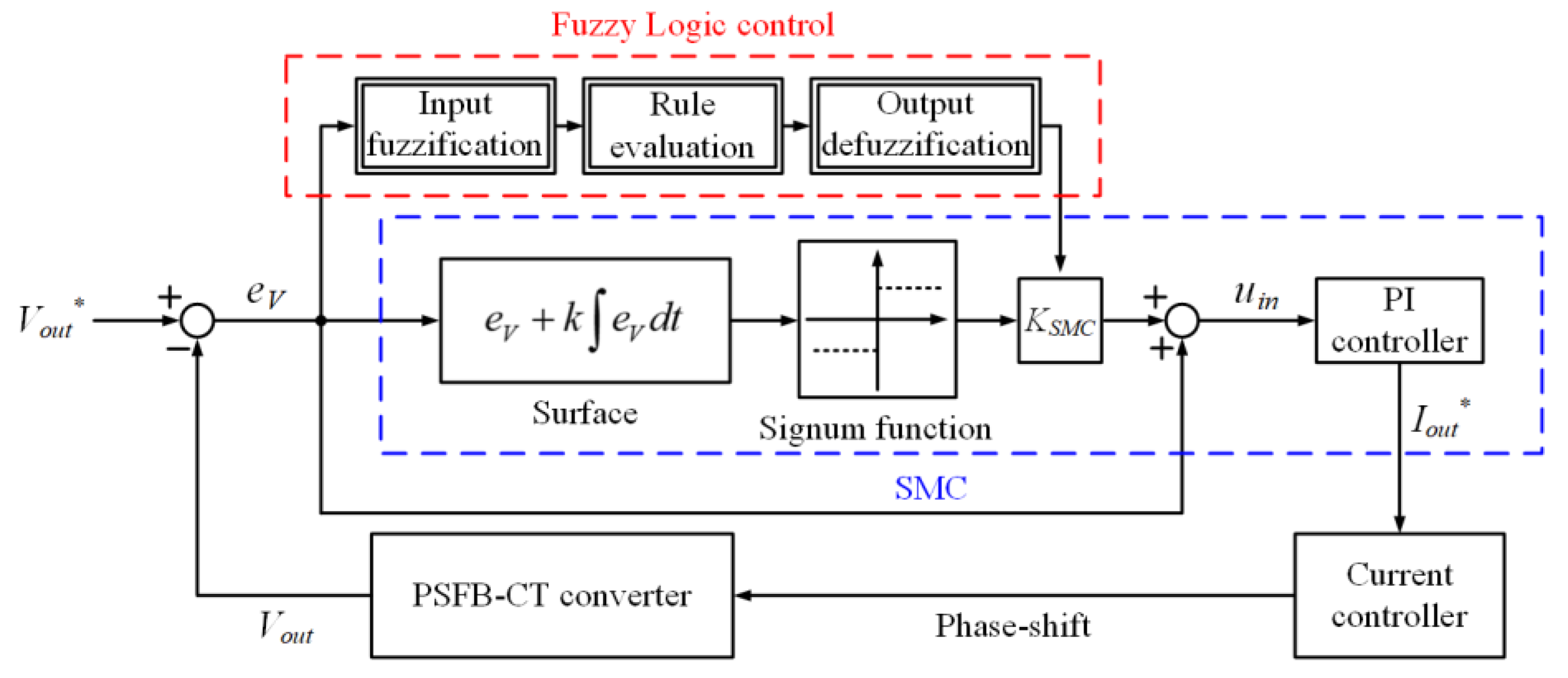
Figure 3 shows the proposed control block diagram of the PSFB-CT converter using hybrid fuzzy SMC. First, in the SMC, an output voltage error (
eV) is calculated by the difference between the reference output voltage (
Vout*) and the real output voltage (
Vout) of the PSFB-CT converter. This is applied to the input of the SMC and a sliding plane of the SMC is obtained by the
eV. Since the sliding plane is an important variable that determines the control performance of the SMC, it is designed by various forms suitable for each system [
19,
22,
23,
24]. In this paper, it was designated as
Surface, which is designed with the
eV and its integral term as Equation (3).
where
k is a sliding coefficient, which is set to 1 in this paper.
The
Surface passes the signum function to relieve the chattering phenomenon, which is expressed as Equation (4).
Additionally, the error (
eVSC) of the VSC using the SMC is obtained through the sgn(
Surface) multiplies by the gain (
KSMC) of the SMC. Finally, the input of the PI controller in the SMC is formed in parallel with the
eV and
eVSC as in Equation (5).
The uin is controlled to zero by the PI controller and the reference output current (Iout*) is obtained as a result of the SMC.
The output current (
Iout) of the PSFB-CT converter is controlled to the
Iout* by the current controller based on the PI control, which is modeled as an inner loop of the proposed hybrid fuzzy SMC for the output voltage control. In order to design the current controller based on the PI control, in general, the linearized model of the PSFB-CT converter should be determined by using a small signal analysis in general. In addition, since the PSFB-CT converter contains a center-tapped rectifier, the small signal analysis of the PSFB-CT converter is modeled with the synchronous buck converter as a form of two phase interleaved. By using the small signal analysis, the output voltage and current of the PSFB-CT converter are modeled linearly. As a result, the transfer function of the current controller, which controls the output current, is represented by the linearized model of the output voltage and current [
31]. Finally, a phase-shift is obtained as a result of the current controller and the PSFB-CT converter drives using the phase-shift.
In the SMC, as shown in
Figure 3, the
uin is composed of the
eV and
eVSC that lead to the formation of a linear structure and the VSC, respectively. Therefore, the SMC for the PSFB-CT converter has a fast dynamic characteristic and is robust to internal parameter variation and external disturbance [
29]. However, in the case where the
KSMC is increased to achieve the fast dynamic characteristic of the SMC for the PSFB-CT converter, the ripple of the
Vout is also increased due to the chattering phenomenon, which causes an unstable system. Therefore, in order to supplement this disadvantage of the SMC, the
KSMC was properly changed by the fuzzy logic control with the
eV in the proposed control method as shown in
Figure 3.
3.2. Stability Analysis of the Hybrid Fuzzy SMC
The transfer function of the PSFB-CT converter is necessary to analyze the stability of the hybrid fuzzy SMC for the PSFB-CT converter. However, it is difficult to obtain the accurate transfer function of that considering the operating modes. Therefore, in this paper, the hybrid fuzzy SMC for the PSFB-CT converter is treated as a black-box model, which is able to analyze with only input and output discrete data. In order to analyze the discrete data, in this paper, the least square parameter estimation algorithm is used [
32,
33]. As a result, the discrete transfer function of the hybrid fuzzy SMC can be built based on the results of the parameter estimation. It is converted to a continuous transfer function, which is expressed as in (6), using the zero-order-hold method [
33].
where
kvps and
kvis are proportional and integral gain of the voltage controller based on the hybrid fuzzy SMC, respectively. In addition,
kcps and
kcis are proportional and integral gain of the current controller based on the PI control, respectively. By using the
H(
s) as in (6), the stability of the hybrid fuzzy SMC can be analyzed with the bode diagram and the poles and zeros on complex plane as follows.
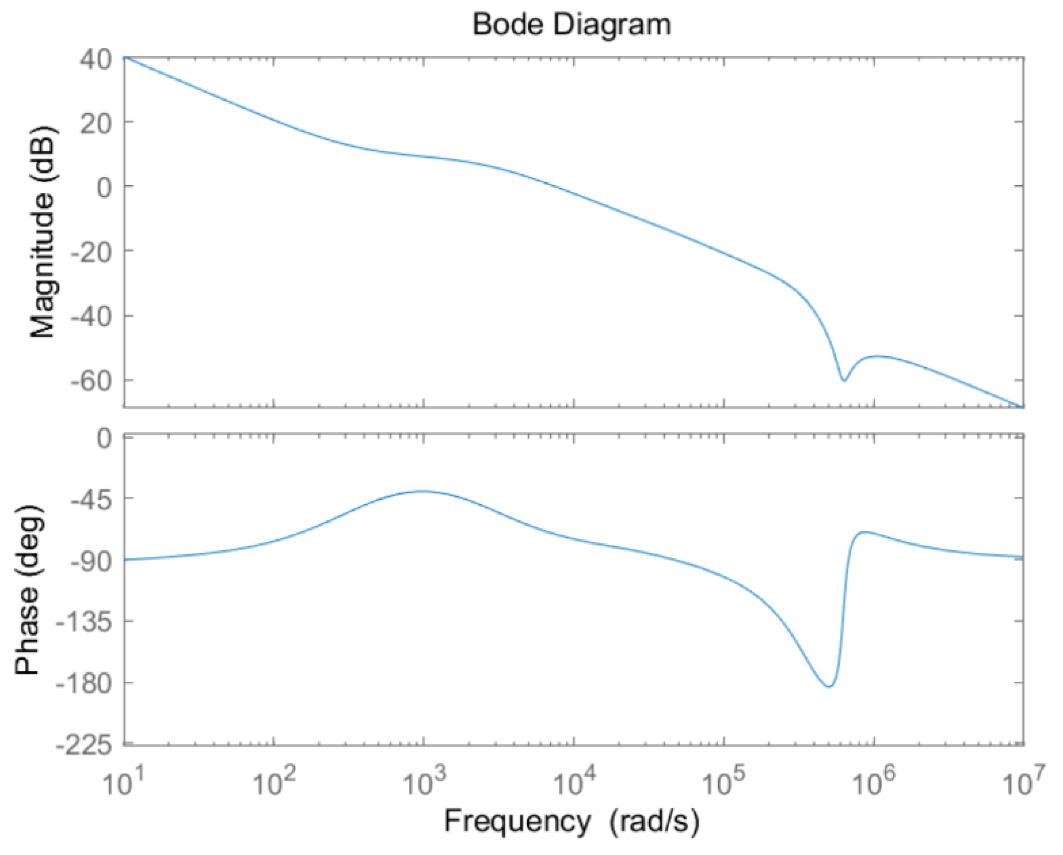
Figure 4 shows the bode diagram of the transfer function
H(
s). In the
H(
s), the
kvps,
kvos,
kcps, and
kcis are set to 0.995456, 2816, 0.00658924, and 2.33, respectively. In
Figure 4, the crossing frequency is about 10,000 rad/s, the gain margin (GM) is 41 dB, and the phase margin (PM) is 108°. Therefore, through the stability analysis using the bode diagram, it is proved that the hybrid fuzzy SMC for the PSFB-CT converter is stable.
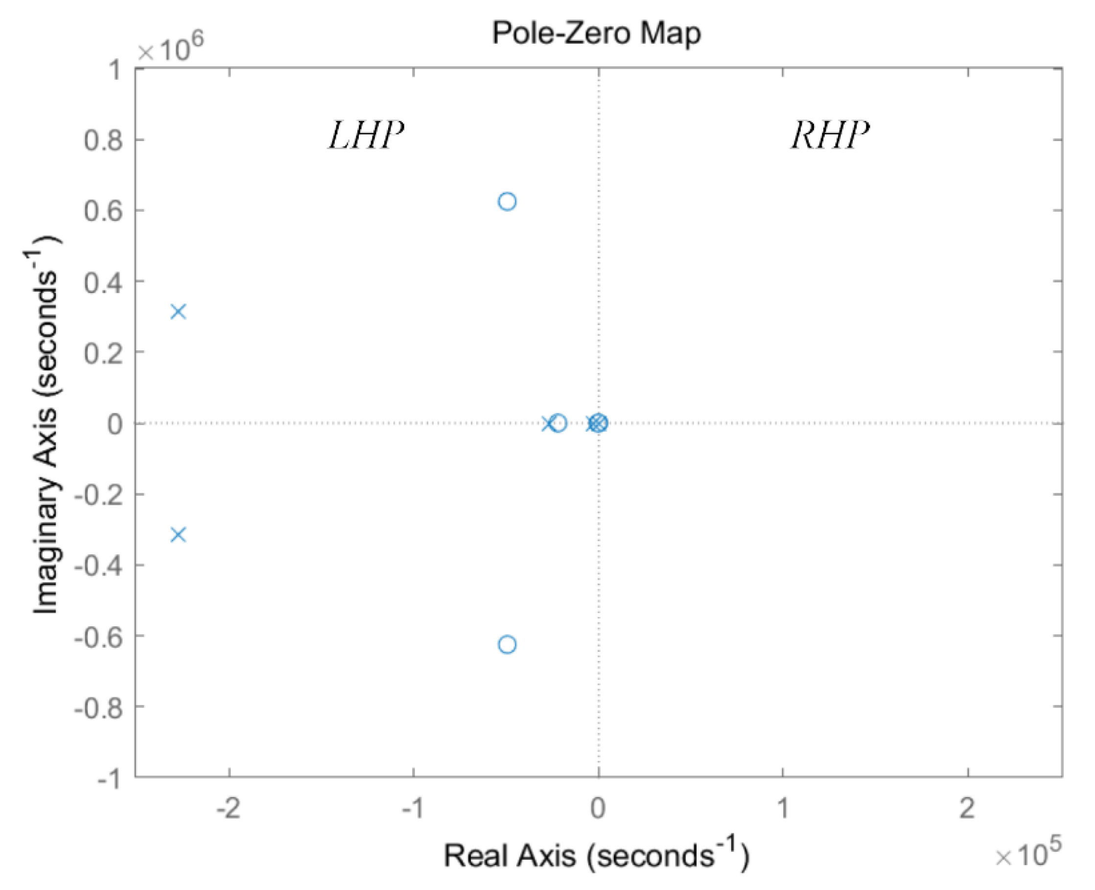
In addition,
Figure 5 shows the poles and zeros of the transfer function
H(
s) on complex plane. In
Figure 5, all of the poles are positioning in the left half plane (LHP). Therefore, through the stability analysis using the poles and zeros on complex plane, it is also proved that the hybrid fuzzy SMC for the PSFB-CT converter is stable.
3.3. Design of Fuzzy Logic Control
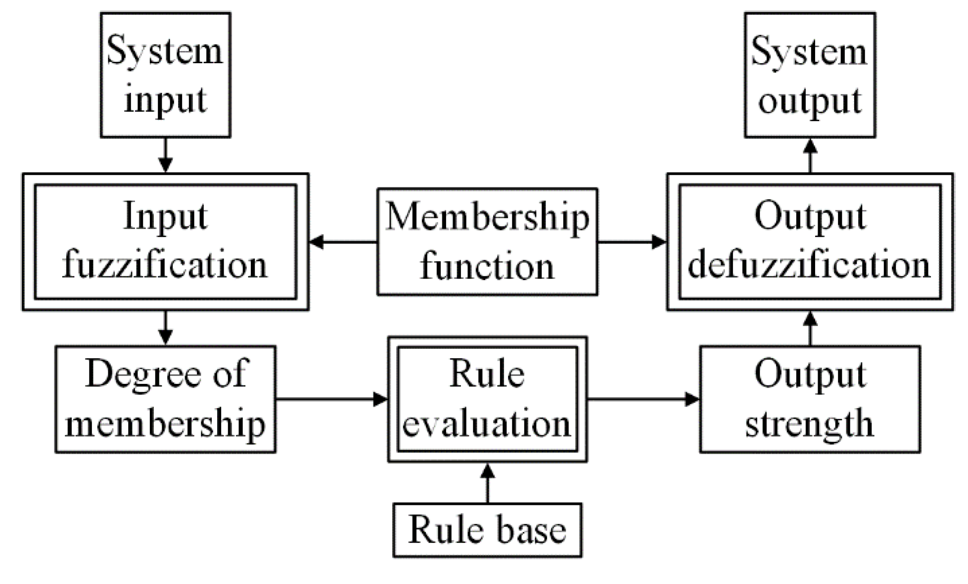
The fuzzy logic control is one of the control methods based on a mathematical system analyzing analog values.
Figure 6 shows the data flow of the fuzzy logic control. It is mainly classified into three major transformations: an input fuzzification, a rule evaluation, and an output defuzzification. By using the three major transformations in the data flow of the fuzzy logic control, the system output of the fuzzy logic control can be obtained from the system input [
34,
35,
36,
37,
38]. In other words, in this paper, the system input and output were the
eV and the
KSMC, respectively. As a result, the appropriate
KSMC for reducing the ripple of the
Vout depending on the
eV can be obtained by using the fuzzy logic control.
The input fuzzification is the process that the system input assigns to one or several membership functions, which are pre-defined depending on the value of the system input. The number and shape of the membership function determine the dynamic characteristic and stability of the fuzzy logic control. Through input fuzzification using the membership function, a degree of membership (DOM) is obtained, which indicates the degree of belonging for each system input to the membership function. The rule evaluation is the process that an output strength based on the DOM is decided by using the if-then grammar. The output strength indicates an influence of the system input that affects the system output. Finally, the output defuzzification is the process that produces a quantifiable result in the fuzzy logic control and calculates the system output of the fuzzy logic control by using the pre-defined membership function, corresponding DOM, and output strength. In this paper, the center of gravity (COG) defuzzification method is used for the fuzzy logic control because it is the most popular defuzzification method [
39]. In the COG defuzzification method, the system output is calculated as a sum of multiplication between the DOM and the corresponding output strength.
3.4. Variation of the KSMC Using Fuzzy Logic Control
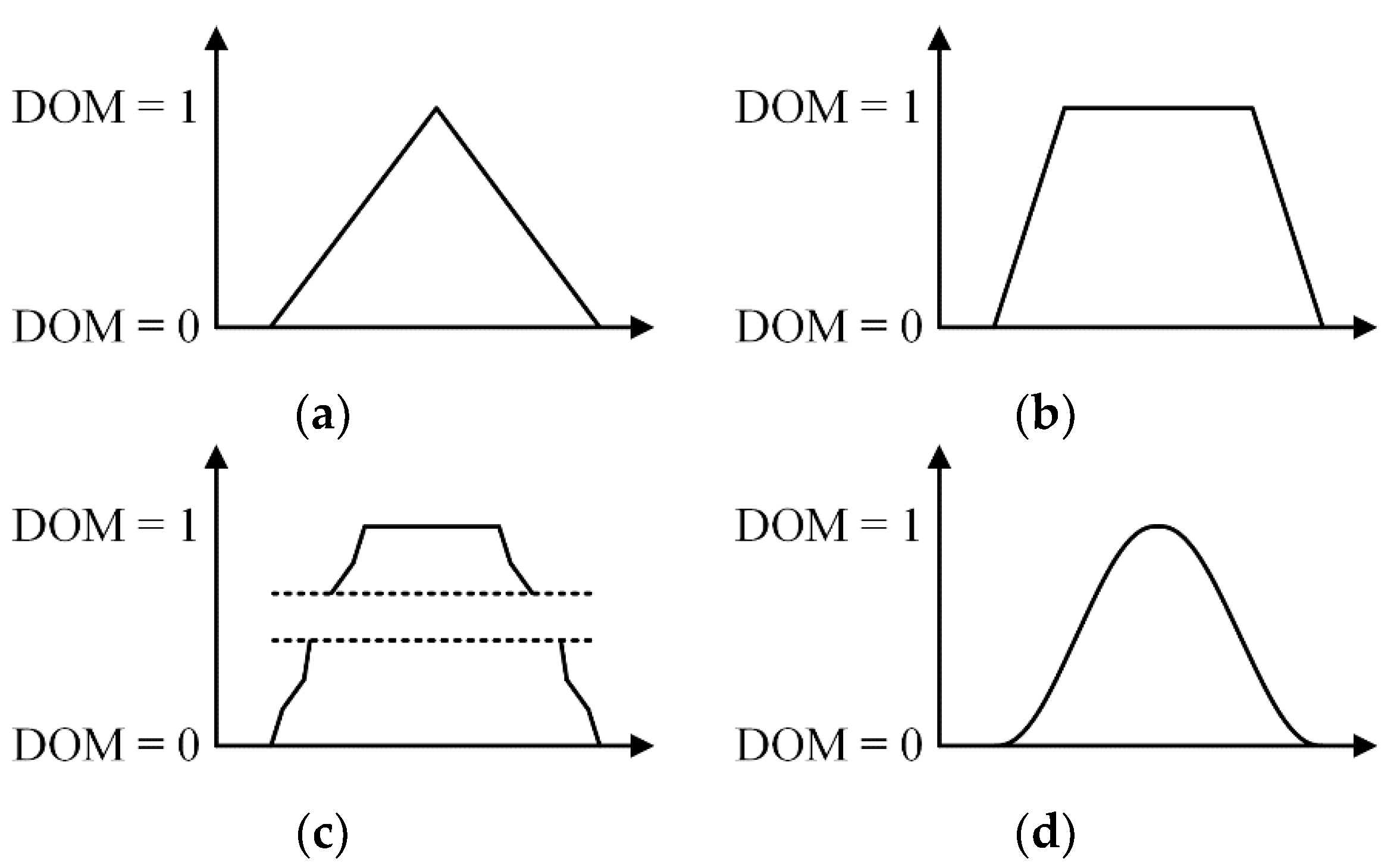
In fuzzy logic control, recently, research regarding the shape of the membership function has actively progressed [
40].
Figure 7 shows the various shapes of the membership function such as triangular, trapezoidal, polygonal, and Gaussian. However, except for the triangular membership function, the others are complicated in terms of implementation.
The performance of the fuzzy logic control using the trapezoidal membership function is almost the same as that using the triangular membership function. However, the trapezoidal membership function is hard to implement when compared with the triangular membership function. In addition, the fuzzy logic control using the triangular membership function has no overshoot and fast dynamic characteristic when compared with that obtained when using the others [
41]. Therefore, in this paper, the triangular membership function with an advantage of convenience of implementation was adopted among various shapes of the membership function [
34,
36].
The number and values of the triangular membership function should be set properly in order to achieve outstanding performance of the fuzzy logic control. The performance of the fuzzy logic control with a number of the membership functions can be improved, however, it has a computation burden. Therefore, in this paper, the number of the membership function was set to five. Additionally, the values of the membership function are determined by experiences and intuitions because the fuzzy logic control is readily customized in human language terms. The output voltage error of 6 V is considered as a large error. Therefore, in this paper, 6 V and −6 V were the values of the triangular membership function allocated as the big positive and negative values, respectively. In addition, the output voltage error of 1 V is considered as a small error, therefore, 1 V and −1 V were the values allocated as the small positive and negative values, respectively.
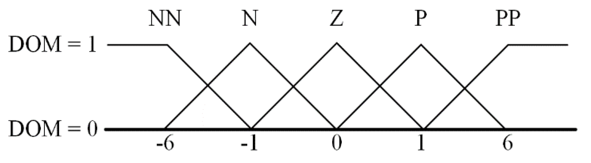
Figure 8 shows the membership functions with the DOM. In this paper, the number of membership functions was set to five and their shape was constructed as a triangle. The five membership functions were composed of NN, N, Z, P, and PP and the DOM was set as zero to 1. The definition of the membership functions is listed in
Table 1. NN and N represent the big and small negative values, which were set to −6 and −1, respectively. Z is the nearly zero and was set as zero. In addition, PP and P were the big and small positive values, which were set as 6 and 1, respectively. In this paper, the values of the membership functions indicate the
eV as the output voltage error.
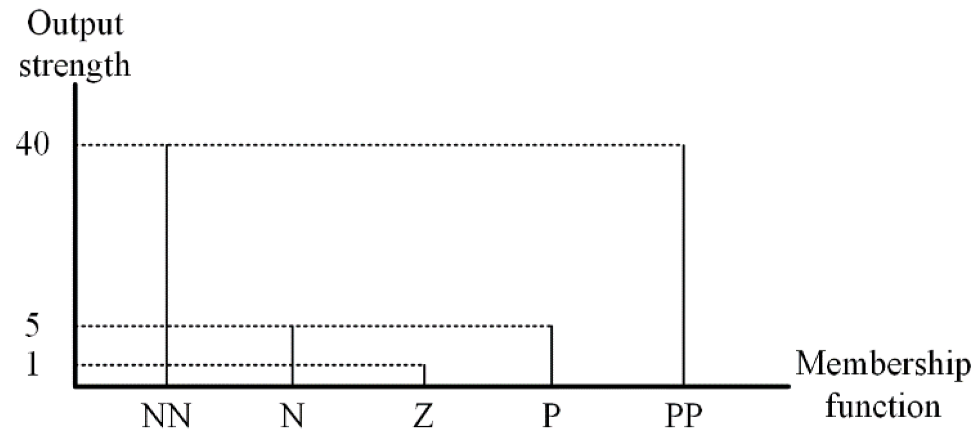
Figure 9 shows the output strength based on the DOM depending on the membership function. The output strength was set to 40, 5, and 1 using the rule evaluation as If-Then grammar:
If the eV is very large as positive, Then the KSMC is very large.
If the eV is slightly large as positive, Then the KSMC is slightly small.
If the eV is nearly zero, Then the KSMC is nearly zero.
If the eV is slightly large as negative, Then the KSMC is slightly small.
If the eV is very large as negative, Then the KSMC is very large.
As a result, with the above rule evaluation, the KSMC can be properly changed smoothly depending on the eV.
In this paper, through the proposed control method for the PSFB-CT converter using the hybrid fuzzy SMC, the ripple of the Vout could be reduced and the dynamic characteristic improved.
The proposed hybrid fuzzy SMC is different from a look-up table, which is just an array that replaces runtime computation with a simple array. Contrary to the KSMC, which is discontinuously changed depending on the look-up table, the KSMC in the proposed hybrid fuzzy SMC is continuously changed by its feedback. Therefore, the KSMC in the proposed hybrid fuzzy SMC is adequate compared with that in the look-up table.
4. Simulation Results
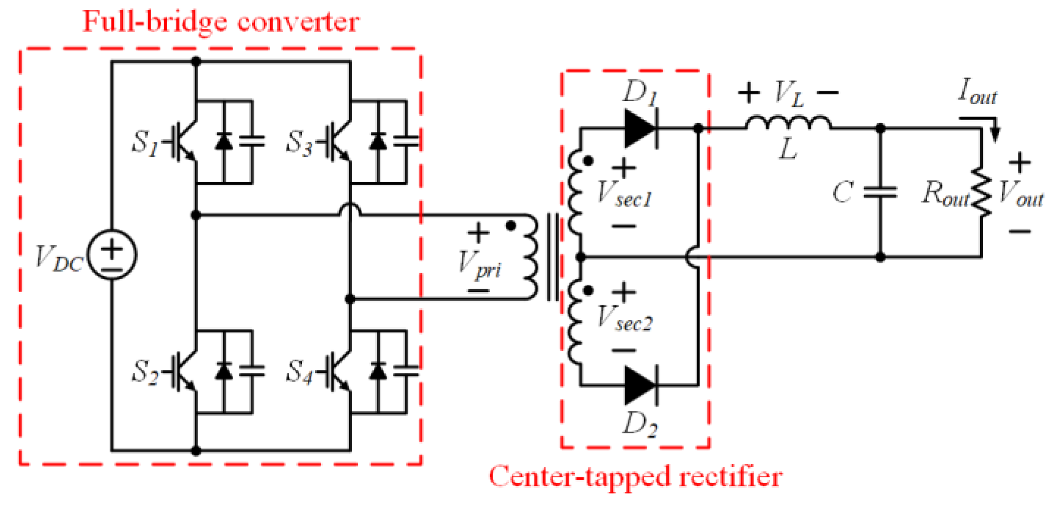
In order to verify the effectiveness of the proposed hybrid fuzzy SMC, a simulation was performed using PSIM software. The simulation circuit diagram was designed as the configuration of the PSFB-CT converter, as shown in
Figure 1. The input DC voltage (
VDC) was set to 300 V and the additional simulation parameters are given in
Table 2. In the voltage controller based on the hybrid fuzzy SMC, the proportional and integral gain are set to 0.995456 and 2816, respectively. Additionally, in the current controller based on the PI control, the proportional and integral gain were set to 0.00658924 and 2.33, respectively.
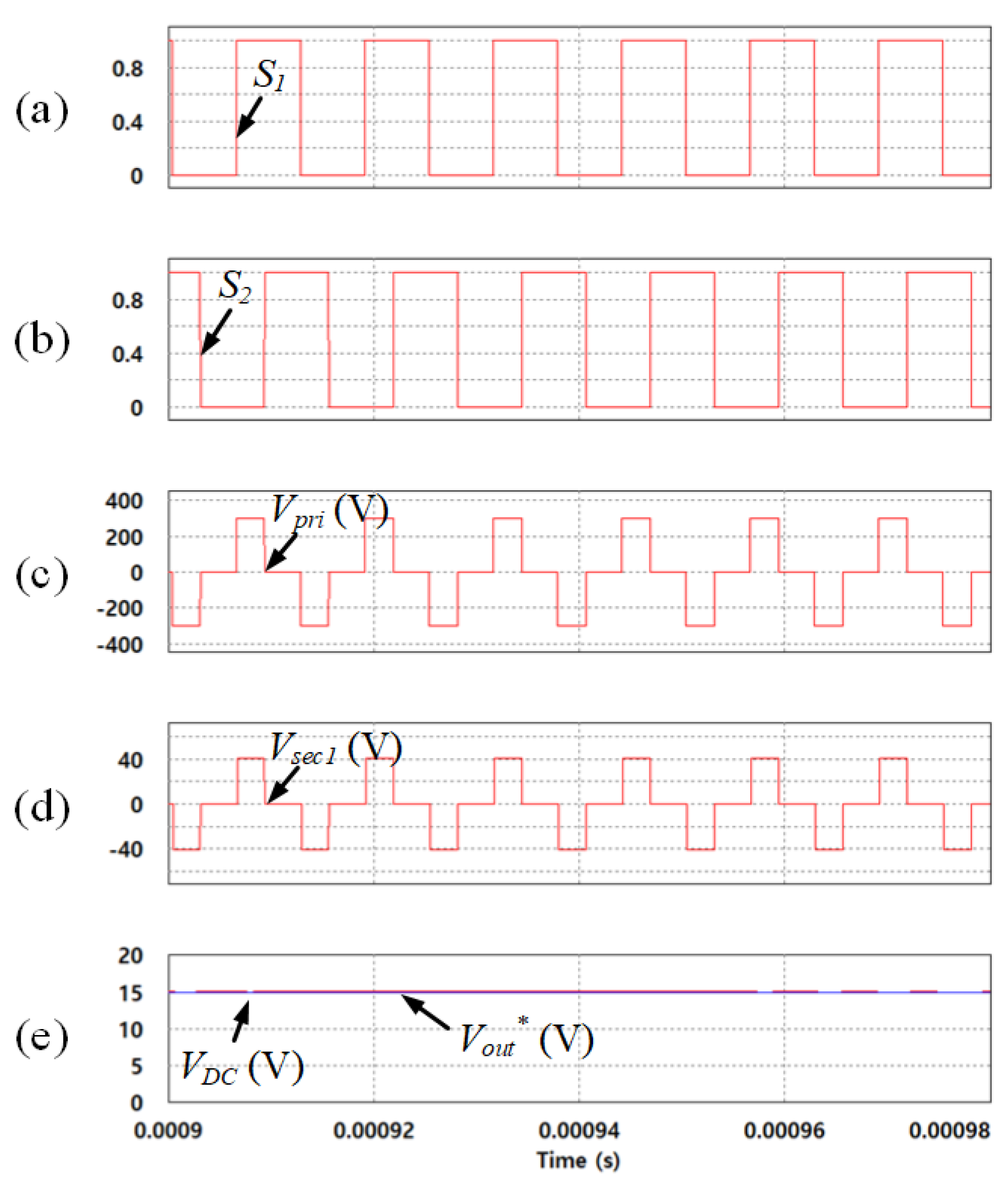
Figure 10 shows the simulation results about operation principle of the PSFB-CT converter. It indicates (a) the operation status of
S1 and (b)
S3, (c) primary (
Vpri), and (d) secondary voltage (
Vsec1) of the transformer, and (e) output DC voltage (
Vout) and reference output voltage (
Vout*). The phase-shift between
S1 and
S3 makes the
Vpri. Since the
VDC was set to 300 V, the
Vpri was 300 V
peak and was reduced to
Vsec1, which was 41 V
peak by the transformer turn ratio of 87:12. Additionally, the
Vsec1 as the pulse waveform became
Vout through the center-tapped rectifier. The
Vout was controlled to the
Vout*, which was set to 15 V.
Figure 11 shows the simulation results of the PSFB-CT converter using the SMC depending on
KSMC, which was set to (a) 0, (b) 1, and (c) 3, respectively. The
Vout* was changed to 15 V from 10 V at 0.01 s and the
Vout was controlled to
Vout*. In
Figure 11a, the
eVSC in
uin as in (5) became a zero because the
KSMC is 0. Therefore, the SMC was performed the same as the PI controller. In contrast to
Figure 11a, in
Figure 11b,c, the dynamic characteristic of the PSFB-CT converter was improved because the
KSMC increased to 1 and 3, respectively. However, in these results, the output voltage and current ripple increased at the same time.
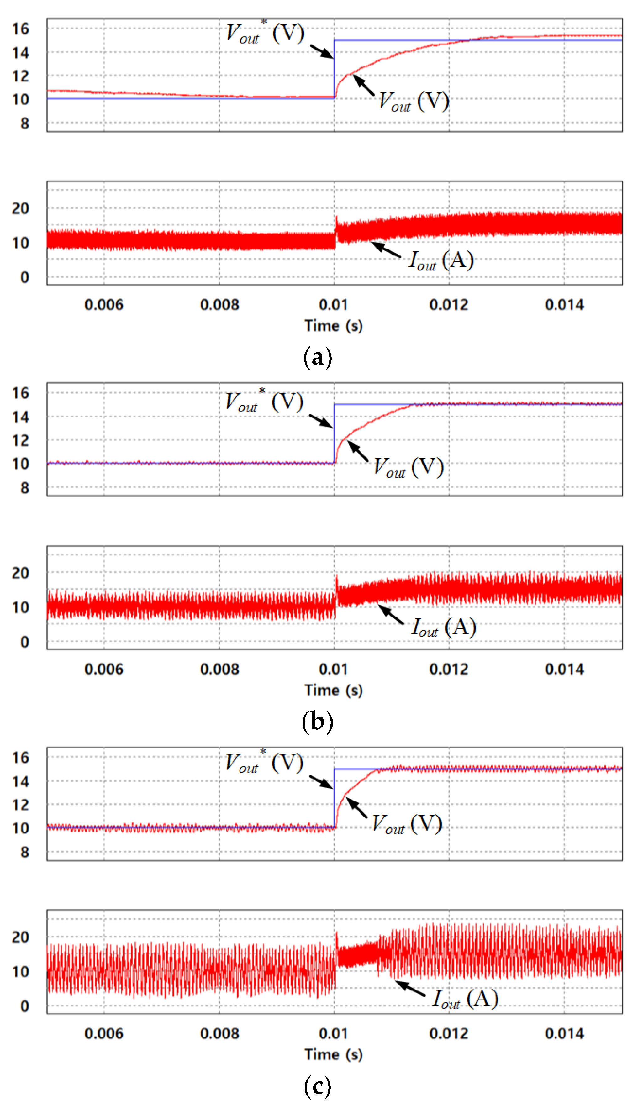
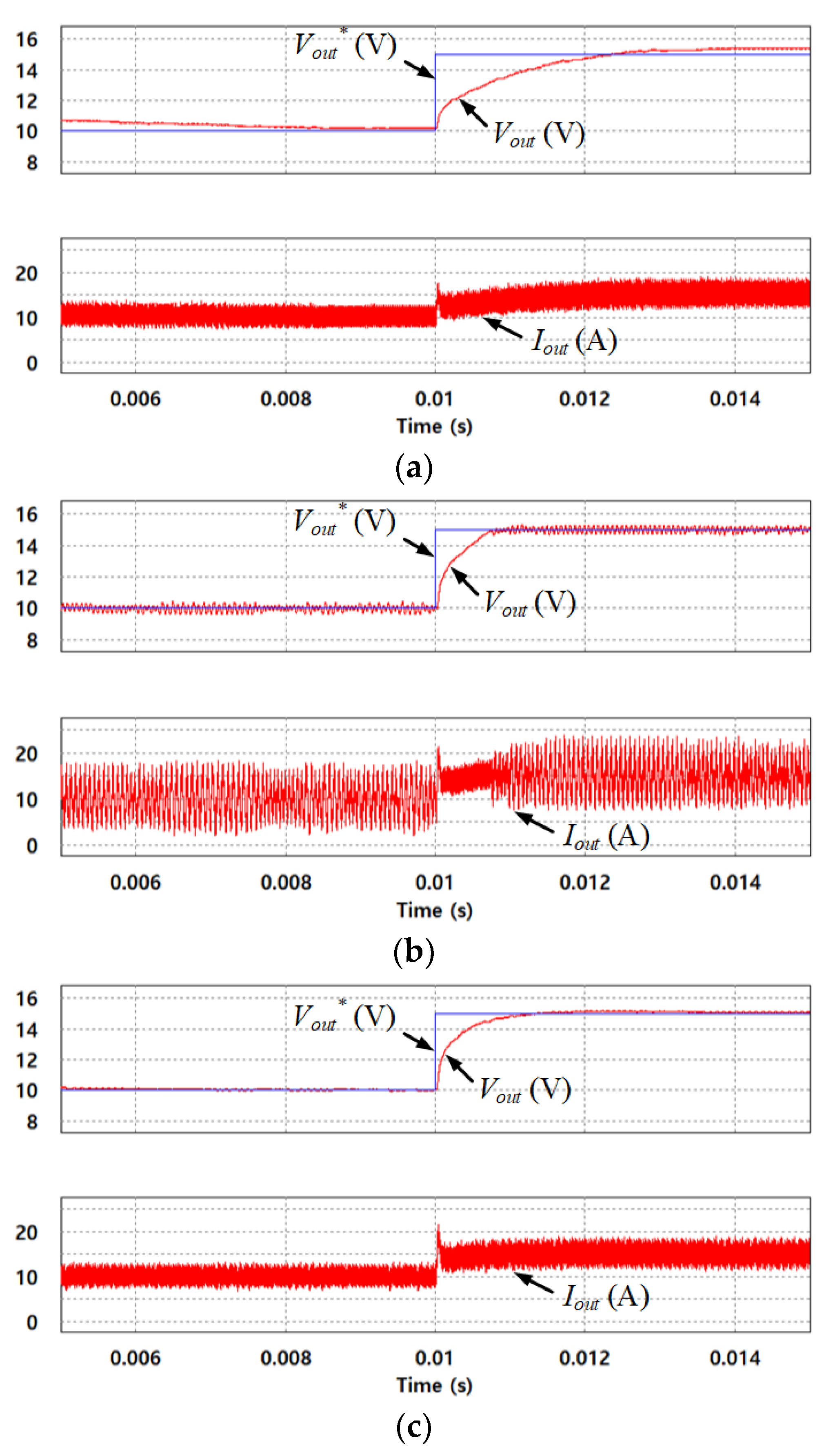
Using the same scenario as that in
Figure 11,
Figure 12 shows the simulation results of the PSFB-CT converter using three different controllers: (a) the PI controller, (b) SMC, and (c) proposed hybrid fuzzy SMC. In
Figure 12a with the PI controller, the dynamic characteristic of the PSFB-CT converter was undesirable, where the settling time was about 2 ms. In the steady state, the output voltage ripple was nearly zero and the output current ripple was relatively small. In
Figure 12b with the SMC, the dynamic characteristic of the PSFB-CT converter was improved, where the settling time was about 0.8 ms when compared to that of the PI controller as shown in
Figure 12a. However, in the steady state, the output voltage and current ripple were increased by the chattering phenomenon. Finally, in
Figure 12c with the proposed hybrid fuzzy SMC, the dynamic characteristic of the PSFB-CT converter was also improved, where the settling time was about 0.9 ms when compared with the PI controller. It was desirable compared to the SMC. In the proposed hybrid fuzzy SMC, the
KSMC is properly varied depending on the output voltage error. As a result, the dynamic characteristic of the PSFB-CT converter is improved and the output voltage and current ripple are decreased by varying the
KSMC.
5. Experimental Results
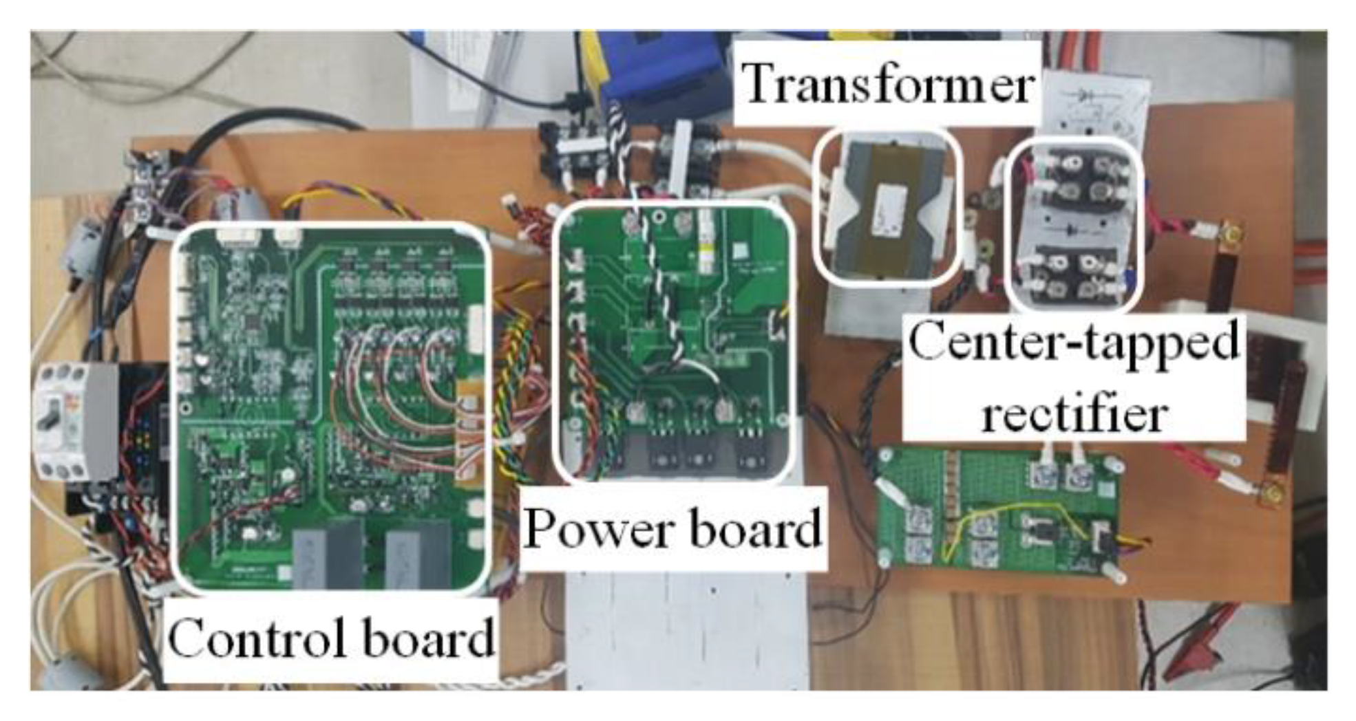
In order to demonstrate the performance of the proposed control method for the PSFB-CT converter using the hybrid fuzzy SMC, experiments were conducted.
Figure 13 shows the experimental setup, which was composed of a control board, a power board, transformer, and center-tapped rectifier. The power for the experimental setup was generated by the switching mode power supply (SMPS) of Power Plaza, Seoul, Korea. The control board consisted of a micro controller unit (MCU) using the SPC570S50E1 of ST microelectronics, Geneva, Switzerland. The control method for the PSFB-CT converter using the proposed hybrid fuzzy SMC was programmed on the MCU. The control board obtained the signals from the input–output voltage and current sensors to control the PSFB-CT converter and transferred the PWM signals obtained from the proposed hybrid fuzzy SMC to the power board. Additionally, the
Vpri was generated by the operation of the PSFB-CT converter in the power board, which was composed of four MOSFETs using a SCT3030KL of a ROHM semiconductor, Kyoto, Japan. Finally, through the transformer of Chang Sung electronics, Gunpo, Korea, and the center-tapped rectifier composed of two diode-modules using STPS200170TV1Y of ST microelectronics, Geneva, Switzerland, the
Vout came out, which connected to the resistance load. The experimental parameters were the same as the simulation parameters given in
Table 2.
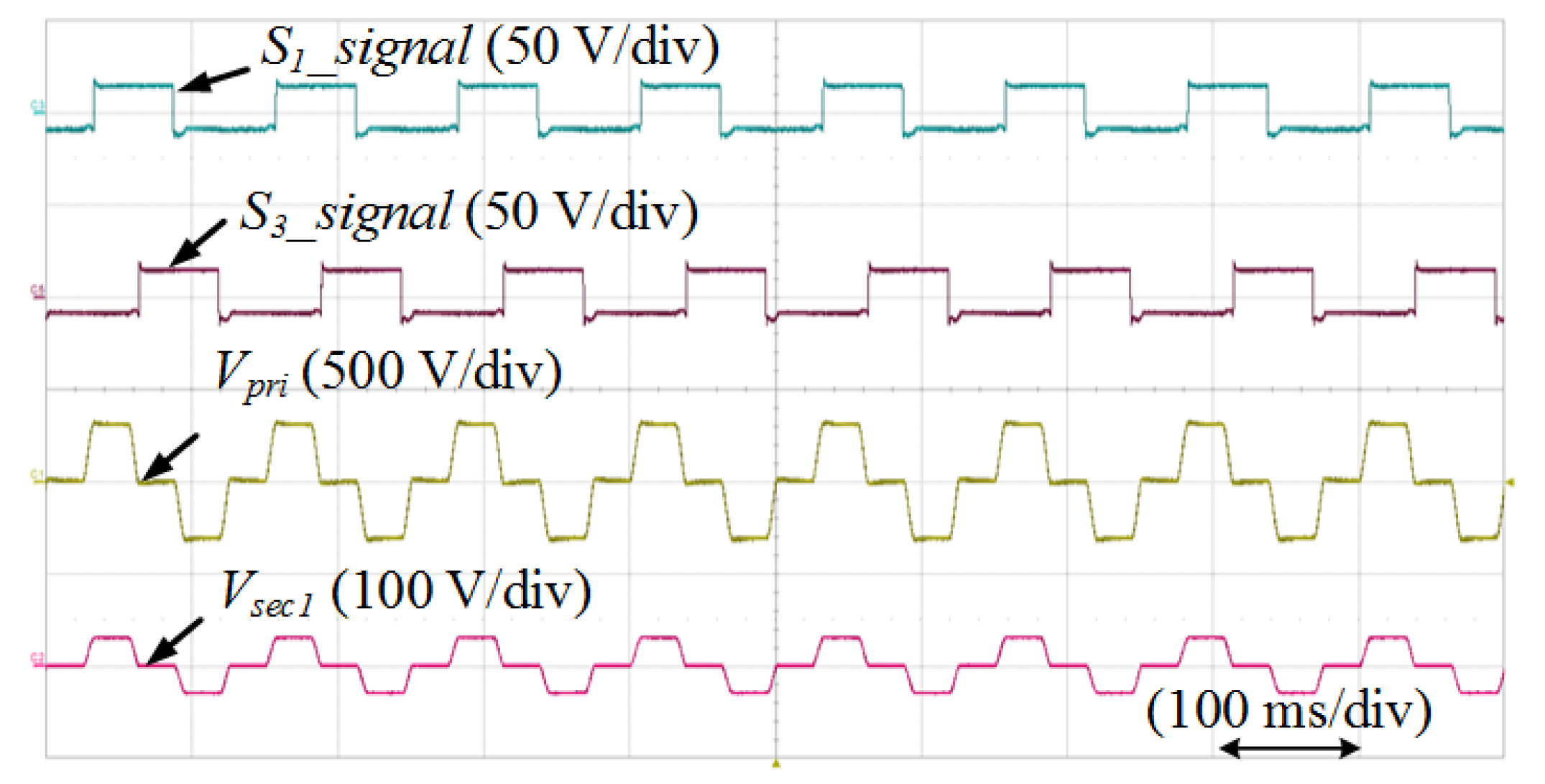
Figure 14 shows the experimental results on the operation principle of the PSFB-CT converter when the
Vout* was 15 V and indicates the gate signals (
S1_signal and
S3_signal) of
S1 and
S3, the primary voltage (
Vpri), and secondary voltage (
Vsec1). The phase-shift between
S1 and
S3 makes the
Vpri, which is transferred to the secondary side of the transformer as the
Vsec1.
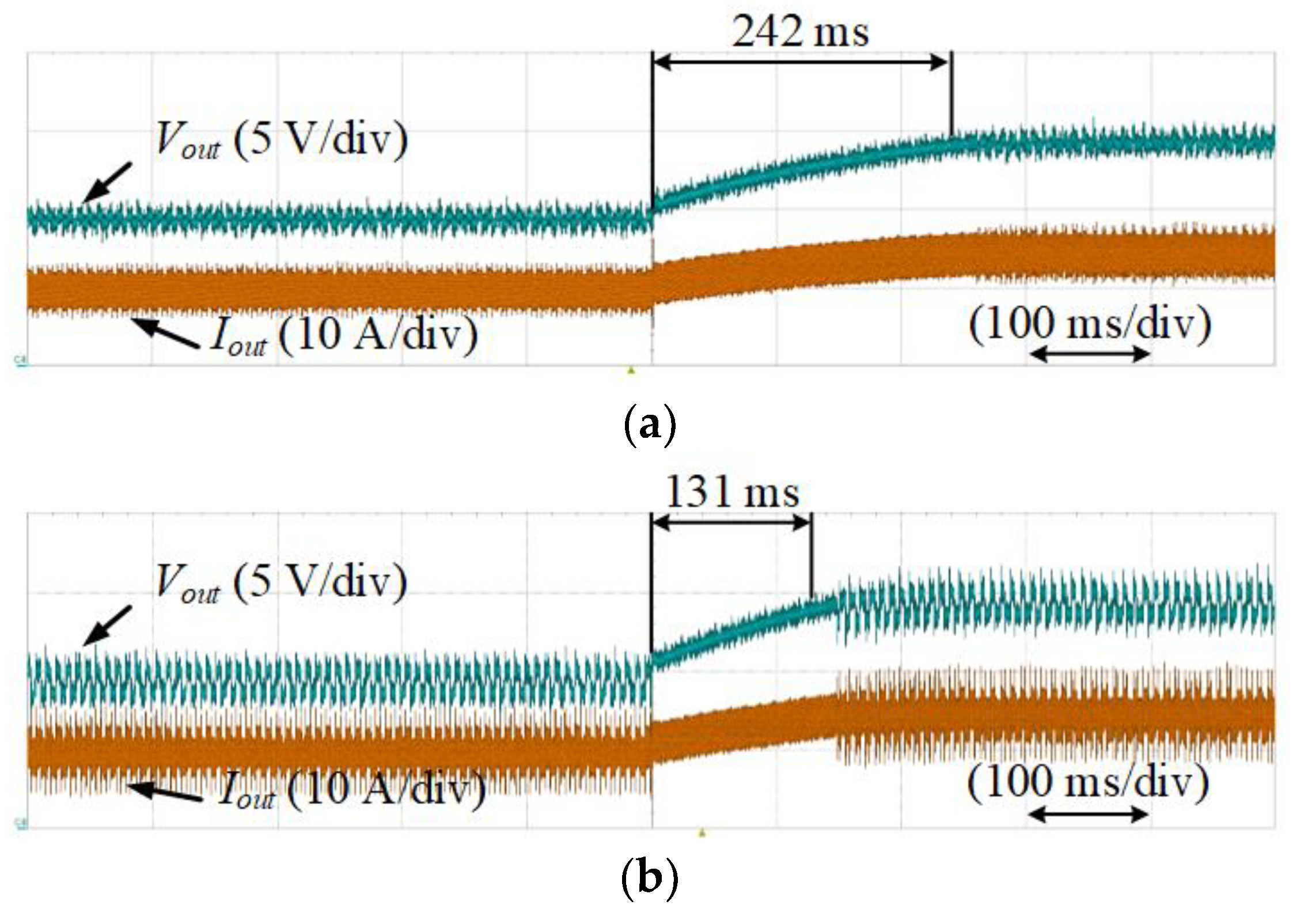
Figure 15 shows the experimental results of the PSFB-CT converter using the SMC depending on the
KSMC, which was set to (a) 1 and (b) 3, respectively. The
Vout* was changed to 15 V from 10 V and the
Vout was controlled to
Vout*. In the case that the SMC is used for the PSFB-CT converter, the dynamic characteristic is improved depending on the
KSMC. In
Figure 12a,b with the
KSMC as 1 and 3, the settling time was about 242 ms and 131 ms, respectively. However, in the steady state, the output voltage and current ripple were increased, which can make system unstable.
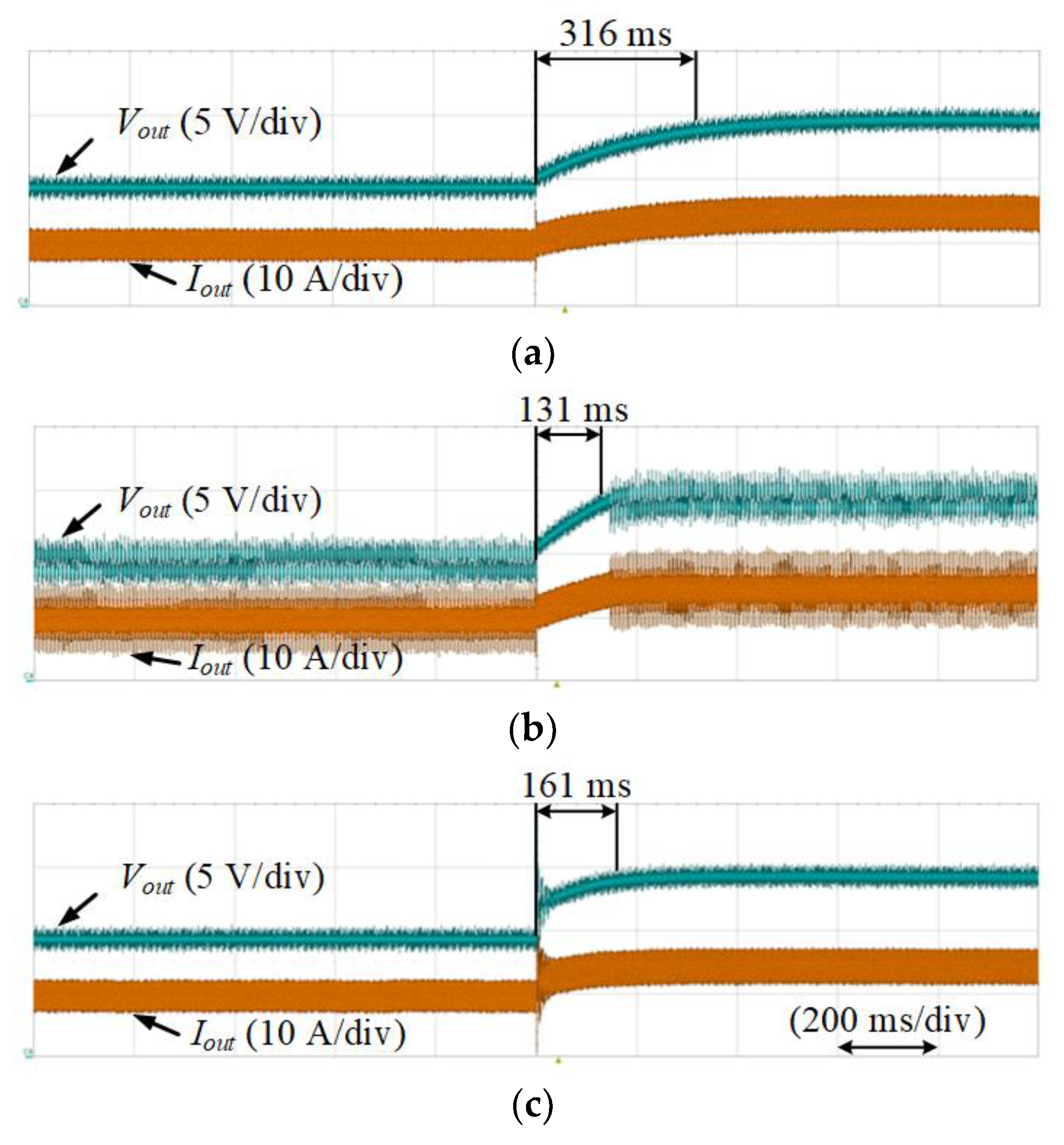
In the same scenario as that in
Figure 15,
Figure 16 shows the experimental results of the PSFB-CT converter using three different controllers: (a) the PI controller, (b) SMC, and (c) proposed hybrid fuzzy SMC. In
Figure 16a with the PI controller, the dynamic characteristic of the PSFB-CT converter was undesirable, where the settling time was about 316 ms, which is relatively long. In the steady state, the output voltage ripple was almost zero and the output current ripple was relatively small. In
Figure 16b with the SMC, the dynamic characteristic of the PSFB-CT converter was improved where the settling time was roughly 131 ms in comparison to the PI controller. However, in the steady state, the output voltage and current ripple are increased by the chattering phenomenon. In the proposed hybrid fuzzy SMC as shown in
Figure 16c, the dynamic characteristic of the PSFB-CT converter was also improved, where the settling time was roughly 161 ms when compared to the PI controller. In addition, in contrast to the SMC as shown in
Figure 16b, the output voltage and current ripple were relatively small. As a result, by properly varying the
KSMC depending on the output voltage error in the proposed hybrid fuzzy SMC, the dynamic characteristic is improved and the output voltage and current ripple are decreased in the steady state.


