1. Introduction
Massive multiple-input multiple-output (MIMO) transmission technique has gained a lot of attention in recent decades [
1,
2,
3,
4,
5,
6,
7,
8,
9,
10,
11,
12,
13], since it can achieve significant improvement in terms of the energy and spectral efficiency while using simple signal processing [
1,
2,
3,
4]. Massive MIMO systems prefer operating in the time division duplex (TDD) mode in which users must synchronously send mutually orthogonal pilot signals to the corresponding base station (BS) so that the BS can estimate the channels. This method uses the estimated channels to perform signal processing [
5,
6,
7,
8,
9,
10,
11,
12,
13], so that pilot signals account for a significant part of the total coherent interval, which decreases the spectral efficiency. In addition, when the number of users is large, the orthogonal pilot set has to be reused in every cell, which leads to pilot contamination problems; this is considered as a performance bottleneck in massive MIMO systems.
The authors of [
8] investigate the power allocation to improve the spectral efficiency, this require a large information exchange in backhaul of system between BSs or between BSs and users. Besides, the algorithm to optimize the power is quite complex. Some semi-blind and blind channel estimation methods in uplink massive MIMO have been proposed. In [
9], the authors proposed an eigenvalue decomposition-based method to blindly estimate the uplink channel from the data signal. However, they assumed that the number of antennas was very large such that the channel vectors become mutually orthogonal. The authors of [
10] derived a new channel estimator based on subspace projection. However, this channel estimation algorithm relies heavily on the eigenvalues of the channel matrix. Interestingly, the authors of [
11] proposed an energy detection scheme in which data symbols could be detected without relying on estimated channels. The scheme used in [
11] requires designing unique modulated signal constellation for each user in the system. Another promising technique that does not require estimated channels is differential modulation, but it has not received much attention in the massive MIMO research field until now. In [
12], differential quadrature amplitude modulation (DQAM) was proposed for massive MIMO systems. The modulation scheme used in [
12] was based on the asymptotic behavior of the channel when the number of BS antennas goes to infinity; however, the authors of [
12] did not show the detector when the number of BS antennas is finite. The authors of [
13] generalized the QAM detector in [
12] and proposed a new detector and non-coherent distance with better performance when the number of BS antennas is not very large. The differential encoding part of [
13] was done via the look-up table algorithm used in [
14,
15]; this is known as the optimum encoding algorithm for differential modulation. Besides, both [
12,
13] can only detect two consecutive symbols at a time. Recently, the authors of [
16] developed a new differential detector based on multiple-symbol differential detection (MSDD) and the generalized likelihood ratio test (GLRT) criterion. However, the authors of [
16] only consider the case of M-ary Phase Shift Keying modulation (M-ary PSK).
In this paper, we propose a novel multiple-symbol detector for DQAM based on the maximum likelihood metric, which can detect more than two symbols at a time and varies following channel condition to adapt better with the change in environment. In addition, we propose a novel distance which can be used to encode and decode data by using the look-up table algorithm in [
14,
15] for DQAM encoding. Since the proposed scheme varies following the change in channel statistic information while the schemes in [
12,
13] are unchanged, they adapt better to the change of environment and show significantly better performance when compared to previous works [
12,
13].
2. System Model and Previous Works
Similar to [
12,
13], we also consider an uplink massive MIMO system consisting of a single-antenna user and a base station equipped with a large number of antennas
. We consider the TDD mode and the block fading model which are popular used in research on massive MIMO system [
1,
3,
5,
7,
8], in which the channel is unchanged in one coherent interval
T. The received signal vector at the
mth BS antenna is modeled as [
1]
where
presents the average signal-to-noise ratio (SNR);
is the transmit signal vector with length
and
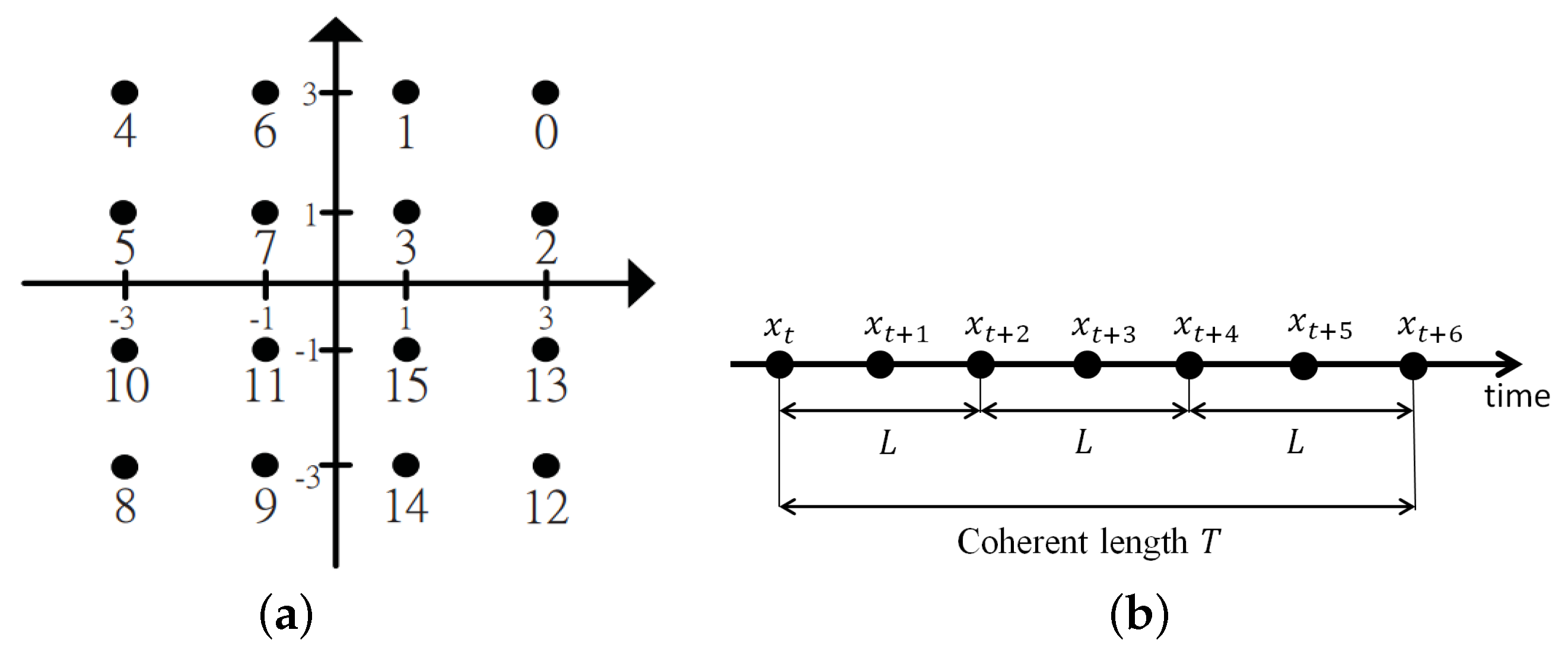
, where elements of
are taken from the conventional QAM constellation as shown in
Figure 1a,
is the additive white Gaussian noise vector at the
mth BS antenna whose entries follow
; and
is the channel coefficient with
. An example of the block fading model and signal vector is illustrated as in
Figure 1b.
For simplicity, we normalize the channel so that
. Since Rayleigh and Rician fading models are very popular in evaluating system performance on both massive and regular MIMO system [
17,
18], we focus on these two models with
and
[
12]. Thus, the channel vector from a user to a BS now can be modeled as
where
represents the Rician factor; In a special case, when
, the channel becomes a Rayleigh fading channel. Additionally,
with the arrival angle
; is the light-of-sight (LOS) component when the antenna spacing is a half of wavelength.
denotes the non-light-of-sight (NLOS) component whose elements follow i.i.d Gaussian variables with zero mean and unit variance.
In [
12,
13], the authors considered two consecutive
tth and
th instants, with channel vectors
; and
, and assumed
. The received signal vector at the
tth instant is given as
where
is taken from a 16-DQAM constellation based on [
19]. With a very large number of BS antennas
M, they have
Eventually, the signal symbol at the
tth instant can be detected as
in which
can be mapped back to the information symbol by the encoding rule of [
19]. However, the authors of [
12] did not propose a detector for when the number of BS antennas
M is finite. The authors of [
13] generalized the detector in [
12] as ([
13], Equation (
6)), which can be applied for any value of
M. After that, they proposed a new two consecutive-symbol detector based on the conditional probability and a new non-coherent distance as ([
13], Equations (9) and (10)). The new distance in [
13] is used for look-up table algorithm in [
14,
15] for differential encoding.
Particularly, the authors of [
14] had already proved that any differential encoding techniques can be transform equivalently to a differential encoding via a look-up table. Using the algorithm in [
14,
15] to create look-up table for encoding and decoding 16-DQAM signal, a brief explanation of a look-up table is as follows. The readers should refer to [
14,
15] for the details of the algorithm.
Sort all possible codeword pair and in descending order based on their proposed distance.
Arrange all groups: Take codeword pair one by one from the sorted list L. Put two codewords of a pair into the same group if possible; Otherwise, put them into two different groups and the two groups are written into L, which is called the list of near group pairs (near groups means the distance between members in two groups are small, which means there is a big chance that these two groups may be wrongly estimated as each other). Two codewords cannot be in the same group if their first symbols are identical.
Assign modulated symbol to each group based on list L: Take group pairs one by one in order from list L. The number of different bits assigned for the considered two groups taken from L should be as small as possible (since two near groups have big change to be wrongly estimated as each other, this step’s goal is to minimize the bit error).
Some properties of the look-up table are listed up below.
The number of rows in the table are numbers of groups of codewords.
Codewords belong to the same group will encode for the same information.
Number of codewords in each group are the same.
The important metric to generalize the look-up table is the non-coherent distance between any codewords, which is one of the new propose in this paper.
General rules of generating the look-up table is that two codewords with small non-coherent distance should be placed in the same group. Otherwise, they should be putted into different groups.
Moreover, this look-up table can be optimized by using algorithms proposed in [
14,
15]. In this paper, we propose new non-coherent detector, new non-coherent distance and apply the algorithm in [
14,
15] to generate the look-up table. We compare the performance of the proposed detector and distance to the existing detectors and distances proposed in [
12,
13]. Due to the limitation of length, we would like to skip the detail of the look-up table algorithm and refer interested readers to [
14,
15].
3. New Differential Detector and Non-Coherent Distance
Consider the received signal at
mth BS antenna as in Equation (
1), the conditional probability of the received signal vector
, given transmitted signal vector
, is calculated as
where
is the mean of
and is given as
where
is the determinant of
, and
is the covariance matrix of
, which can be calculated as
Since the proposed detector aims to maximize the summation of the conditional probability of received signal vector
at all BS antennas
, given transmitted signal vector
, the estimated signal vector
can be calculated as
where
presents the vector space of all possible transmitted signal vectors
. Since the natural logarithm function is monotonically increasing, maximizing
is equivalent to maximize
. Finally, the proposed detector is given as
Specially, when the channel is Rayleigh fading, we have
, and the proposed detector becomes
where
is the first quadrant. This means the number of decision values that need to be calculated is reduced by a factor of four, from
to
, with
N-QAM. The reduction occurs since when
, for any codeword
with the first symbol
belongs to the first quadrant of the constellation, there are also three other codewords which have the first symbol
belong to three other quadrants, that have the same estimated vector
as
. In other words, we only need to calculate the decision values of codewords which have the first symbol
belongs to the first quadrant of the constellation in case of Rayleigh fading. To calculate the proposed non-coherent distance, we propose the distance from
to
and the distance from
to
as in Equations (
12) and (
13) based on the proposed detector, Equation (
10), as below:
in Equations (
12) and (
13) are calculated as
The Equation (
12) is the non-coherent distance from
to
, which is based on the assumption that we did send the codeword
but the detector wrongly estimated that
was sent. Inversely, the Equation (
13) is the non-coherent distance from
to
in which, the
was actually sent but the detector wrongly estimated that
was sent. In other words, Equations (
12) and (
13) can be used by likelihood estimator as a distance between two codewords
and
. The larger the values of Equations (
12) and (
13) are, the less chance the detector wrongly estimates between
and
. Eventually, the proposed non-coherent distance is calculated as
In the differential encoding part, we apply the look-up table algorithm for DQAM as in [
14,
15] by using the proposed non-coherent distance in Equation (
15).
The main contribution of these above steps and equations are summed up as follow.
4. Numerical Results
In simulations, we use the conventional 16-QAM constellation and apply the look-up table algorithm in [
14,
15] to differentially encode the information. Particularly, one 4-bit information symbol is encoded into two consecutive 16-QAM points; thus, the non-coherent distance as in Equation (
15) calculated with the length of transmitted signal vectors
is 2. Finally, the look-up table for 16-DQAM has 16 rows presenting 16 different groups; each group contains 16 different vectors
, and all transmitted signal vectors in the same group correspond to the same information symbol. The look-up table for the proposed 16-DQAM scheme with Rician fading channel
and an average SNR
dB is given in
Table 1 as an example. Notice that, in [
14,
15] after generating the look-up table, there is one more step that maps information bit to each group. This step adds a little more improvement in bit error rate performance since groups with small non-coherent distance are mapped to information bit symbols with a small difference in the number of bits. However, in this simulation, we focus on comparing the performance of detector and distance between our proposed ones and previous ones in [
12,
13] so that we skip this step and add the information bit symbols sequentially from first group to last group in the look-up table.
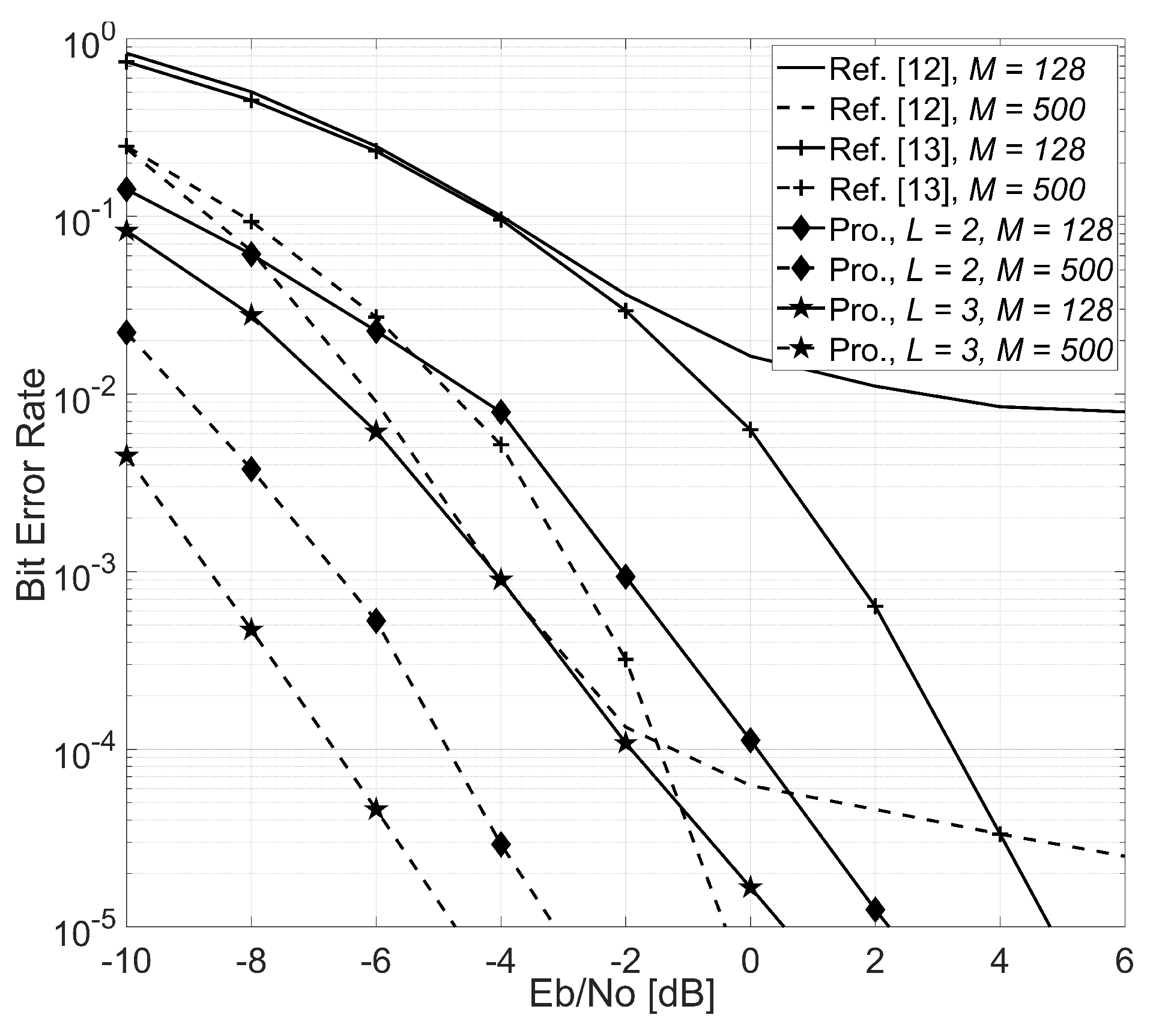
Figure 2 illustrates the simulation results of the proposed 16-DQAM scheme with different lengths of estimated signal vector
and 3, as well as the 16-DQAM schemes in [
12,
13] where the number of BS antennas are
and 500, and the coherent length
. Since the authors of [
12] did not show the detector when
M is finite, we suppose that the 16-DQAM scheme in [
12] uses the generalized detector as in [
13], Equation (
6), and the corresponding non-coherent distance in [
13]. As previously shown in [
12,
13], the 16-DQAM scheme of [
12] shows an error floor when
M is not very large. The proposed scheme significantly outperforms the schemes in [
12,
13] for both
and 500.
Since the schemes in [
12,
13] can only detect two consecutive symbols at a time, we simulate our proposed scheme when the length of signal vector is
. We can clearly see that, with the same channel condition and signal vector’s length, the proposed scheme outperforms the other schemes for
with nearly 3 dB when BER =
. With not so large number of BS antenna
, the significant improvement of the proposed scheme shows a huge potential that it can be deployed in real system. When M increases to 500, the BER performance increases much more further with nearly 5 dB at BER =
, which also shows the advantages of massive MIMO with very large number of BS antennas.
Noticeably, the performance of the proposed scheme is improved significantly when the length of the estimated signal vector
L increases, regardless of the value of
M. The gain is nearly 1.5 dB at BER
when the length
L increases from 2 to 3. When
, the scheme of [
13] only performs better than [
12] at low BER (
) while the performance of the proposed scheme is remarkably better than both [
12,
13]; the gain is approximately 3 dB at BER
in comparison with [
13].
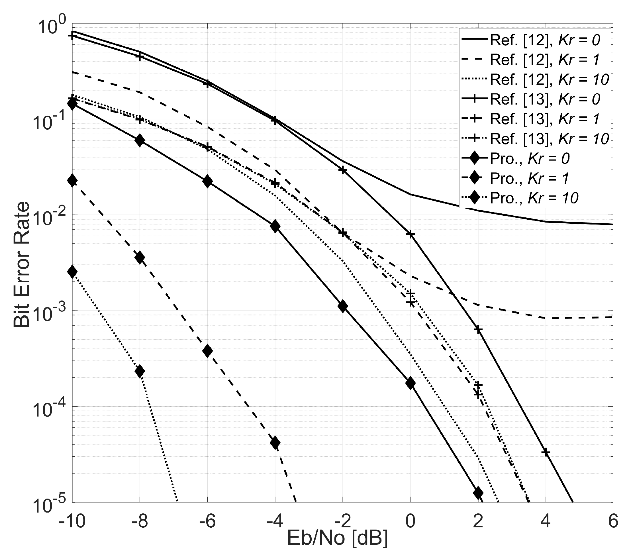
Figure 3 shows the simulation results for the aforementioned schemes under Rician fading with
,
,
and different values of the Rician factor
and 10. Notice that when
, the Rician channel becomes a Rayleigh channel. The error floor still happens when
in the case of [
12]. However, when the LOS component of the Rician channel becomes stronger with
, the error floor seems to disappear and the performance of [
12] is improved much more than [
13]; the performance gap is nearly 1 dB at BER
. The performances of scheme of [
13] are nearly the same with different values of
, this is because the detector in [
13] cancels out the channel coefficient between two consecutively received symbols. The performance of the proposed scheme is the best among three schemes. Even with
(i.e., Rayleigh fading), the performance of the proposed scheme remains better than the other schemes with
or 10. When
is increased from 0 to 1 and 10, the performance of the proposed scheme is improved significantly with gains 5.5 dB and 9.5 dB, respectively. In summary, we conclude that the proposed scheme shows much better performance in Rician channels than in Rayleigh channels.


