Article

Dual-Hop Cooperative Relaying with Beamforming Under Adaptive Transmission in κμ Shadowed Fading Environments

Department of Electronics Engineering, Dong-A University, Busan 604-714, Korea
*
Author to whom correspondence should be addressed.
Electronics 2019, 8(6), 658; https://doi.org/10.3390/electronics8060658
Submission received: 28 March 2019 / Revised: 3 June 2019 / Accepted: 5 June 2019 / Published: 11 June 2019
(This article belongs to the Special Issue Cooperative Communications for Future Wireless Systems)

Abstract

:
In this paper, we analyze the performance of a dual-hop cooperative decode-and-forward (DF) relaying system with beamforming under different adaptive transmission techniques over κ μ shadowed fading channels. We consider multiple antennas at the source and destination, and communication takes place via a single antenna relay. The published work in the literature emphasized the performance analysis of dual-hop DF relaying systems, in conjunction with different adaptive transmission techniques for classical fading channels. However, in a real scenario, shadowing of the line-of-sight (LoS) signal is caused by complete or partially blockage of the LoS by environmental factors such as trees, buildings, mountains, etc., therefore, transmission links may suffer from fading as well as shadowing, either concurrently or separately. Hence, the κ μ shadowed fading model was introduced to emulate such general channel conditions. The κ μ shadowed fading model is a general fading model that can perfectly model the fading and shadowing effects of the wireless channel in a LoS propagation environment, and it includes some classical fading models as special cases, such as κ μ , Rician, Rician-shadowed, Nakagami- m ^ , One-sided Gaussian, and Rayleigh fading. In this work, we derive the outage probability and average capacity expressions in an analytical form for different adaptive transmission techniques: (1) optimal power and rate adaptation (OPRA); (2) optimal rate adaptation and constant transmit power (ORA); (3) channel inversion with a fixed rate (CIFR); and (4) truncated channel inversion with a fixed rate (TIFR). We evaluate the system performance for different arrangements of antennas and for different fading and shadowing parameters. The obtained analytical expressions are verified through extensive Monte Carlo simulations.

1. Introduction

The major difficulties for state of the art and future wireless communication systems are the requirements of higher data rate and improved quality of service [1]. Bandwidth limitation and varying nature of the wireless channel are required to be investigated during the development of a new generation wireless systems [1]. Several advancements have been introduced for 5G and future wireless communication networks such as cooperative relaying systems.
A dual-hop cooperative relaying system is a well-known technique, used in cooperative communication systems to achieve substantial improvements in the overall system performance [2,3,4,5]. Impairments of wireless communication channels are mitigated, and many communication metrics, such as the data rate, coverage range, and link stability, were improved by the deployment of this technique [2,3,4,5]. Mainly, there are two dual-hop relaying techniques, which are categorized as decode-and-forward (DF) and amplify-and-forward (AF) relays. In a DF relaying method, the received signals are first decoded and re-encoded, then forwarded to the destination or end-user, whereas, in an AF relaying method, the received signals from the transmitter or source node are amplified first, then forwarded to the destination [5,6,7,8].
In recent years, the integration of transmit and receive beamforming (i.e., using multiple antennas) in dual-hop relaying received a lot of attention due to its improvement of the quality and reliability of the wireless links [2,3,4,5]. In multi-antenna systems, beamforming techniques are used to improve the signal-to-noise-ratio (SNR) [4].
Besides the beamforming techniques, the implementation of adaptive transmission techniques in a cooperative relaying system provide a better system performance, as compared to non-adaptive transmission techniques [2]. In adaptive transmission schemes, the transmitter adapts the constellation size, transmit power, data rate, coding gain, or any other mixture of such parameters to increase the system performance, according to the channel conditions [2].

1.1. Related Works

Cooperative DF/AF relaying systems have been studied by several authors and their performance was analyzed using different adaptive transmission schemes in various fading environments. An AF relaying system with adaptive techniques was investigated for Rayleigh fading channels in [9]. In [10], using different adaptive schemes in a repetition-based AF relaying system, the authors analyzed the average capacity and outage performance over Rayleigh fading channels, where the selection combining method was used at the destination. The system performance of an opportunistic two-hop AF relaying system was analyzed for Rayleigh fading channels in [11,12,13], where communication occurs through direct (i.e., source-destination) and indirect (i.e., best relay) links. From the set of multiple relays, the best relay was chosen for communication, such that the SNR at the destination is maximized. In [14,15], considering the impacts of outdated channel state information (CSI), a performance analysis of cooperative two-hop AF relay selection schemes was conducted for identical and non-identical Rayleigh fading environments.
The closed-form solution of the outage probability (OP) and average capacity expressions for different adaptive policies were also derived. Furthermore, in [16,17], the DF opportunistic relay and AF partial relay selection systems, with an outdated CSI, were investigated in a Rayleigh fading environment. In [18], the performance of a DF relaying system was investigated in Rician environments. The capacity performance of an AF relaying system, in conjunction with adaptive transmission techniques, was analyzed, in [19,20,21], for Rician and Nakagami- m ^ fading channels. The system performance of a two-hop opportunistic AF relaying system, with antenna selection, was evaluated, in [2], in Rayleigh fading environment. In [22], orthogonal space-time block-codes (OSTBCs) were used in a two-hop multiple-input multiple-output (MIMO) AF relaying system over Nakagami- m ^ fading channels. The effect of antenna correlation on OSTBCs in two-hop AF relaying in Rayleigh fading environments was analyzed in [23]. Furthermore, the multi-hop systems, with DF and AF relays, were studied using adaptive transmission techniques in Rician and Nakagami- m ^ environments in [24,25], respectively.
The work mentioned in the above literature emphasized the performance analysis of dual-hop cooperative relaying systems, in conjunction with various adaptive transmission policies for classical fading channels. However, in a real scenario, transmission links can suffer from fading as well as shadowing, either concurrently or separately. In [26], the κμ shadowed fading model was introduced to emulate such general channel conditions. This model provides us a generalization of different conventional fading models. It deals with the effects of both large-scale fading (i.e., shadowing) and small-scale fading and can transform into κμ, Rician, Rayleigh, One-sided Gaussian, Nakagami- m ^ , and Rician-shadowed fading channels.
The κμ shadowed fading model is widely used for modeling the point-to-point (P2P) and relay links using non-adaptive transmission techniques [4,26,27,28,29,30,31,32,33]. First, in [26], the κμ shadowed fading model was introduced, and the probability density function (PDF), momentum generating function (MGF), and cumulative distribution function (CDF) were derived in closed-form for a P2P communication system. It considers only single-hop P2P channel while our work deals with dual-hop relay channel which is applicable to recent advanced cellular relay systems. The average capacity in a closed-form expression of a P2P system was obtained in [27,28], and the system performance was analyzed for different fading and shadowing parameters. Furthermore, in [29], the system performance was examined in terms of the average capacity and OP, when the signal-of-interest and interferer were experiencing the κμ shadowed fading. In case of cooperative systems, the system performance of a fixed-gain AF relaying system with beamforming was analyzed, in [30], in terms of the OP and error rate. The authors in [4] studied a variable-gain AF relaying system with beamforming, and they derived the exact analytical results for the OP and average capacity. In [31], an AF relaying system with beamforming in a satellite communication system was studied, and the analytical expressions for the SER were obtained. The performance of a DF satellite relaying system was evaluated in [32], and the OP, BER, and average capacity expressions were derived. In [33], a dual-hop DF energy harvesting relaying system was studied in the presence of hardware impairments in κμ shadowed fading environments. A non-linear energy harvester was accounted at the relay node, which restricts the harvested power level, with a saturation threshold. Using the received radio-frequency (RF) signals from the source node, the relay harvests the energy and uses it to send the information to the destination.

1.2. Contributions

To the best of the authors’ knowledge, the performance of a dual-hop DF relaying system with beamforming using adaptive transmission techniques in κμ shadowed fading environment has not been analyzed in the literature. Therefore, in our work, we evaluate the performance of a dual-hop DF relaying system with beamforming using adaptive transmission techniques in κμ shadowed fading environments. We use a relay with a single antenna for communication between two nodes (i.e., the multiple-antenna source and the multiple-antenna destination). We considered a dual-hop relaying system, where mobile equipment (i.e., a relay with a single antenna) assists other transceivers by relaying signals. A similar system design is considered for adaptive and non-adaptive transmission systems in [22] and [34,35,36,37,38,39,40,41,42,43,44], respectively.
Our key contributions are summarized as follows:
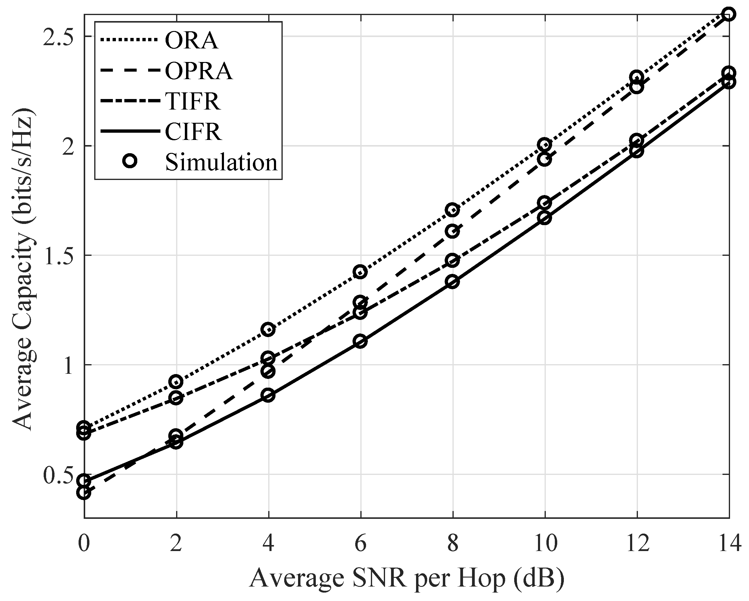
  • We obtain new and exact results in an analytic form for the OP and average capacity using adaptive transmission techniques, such as optimal power and rate adaptation (OPRA), optimal rate adaptation with a constant transmit power (ORA), truncated channel inversion with a fixed rate (TIFR), and channel inversion with a fixed rate (CIFR).
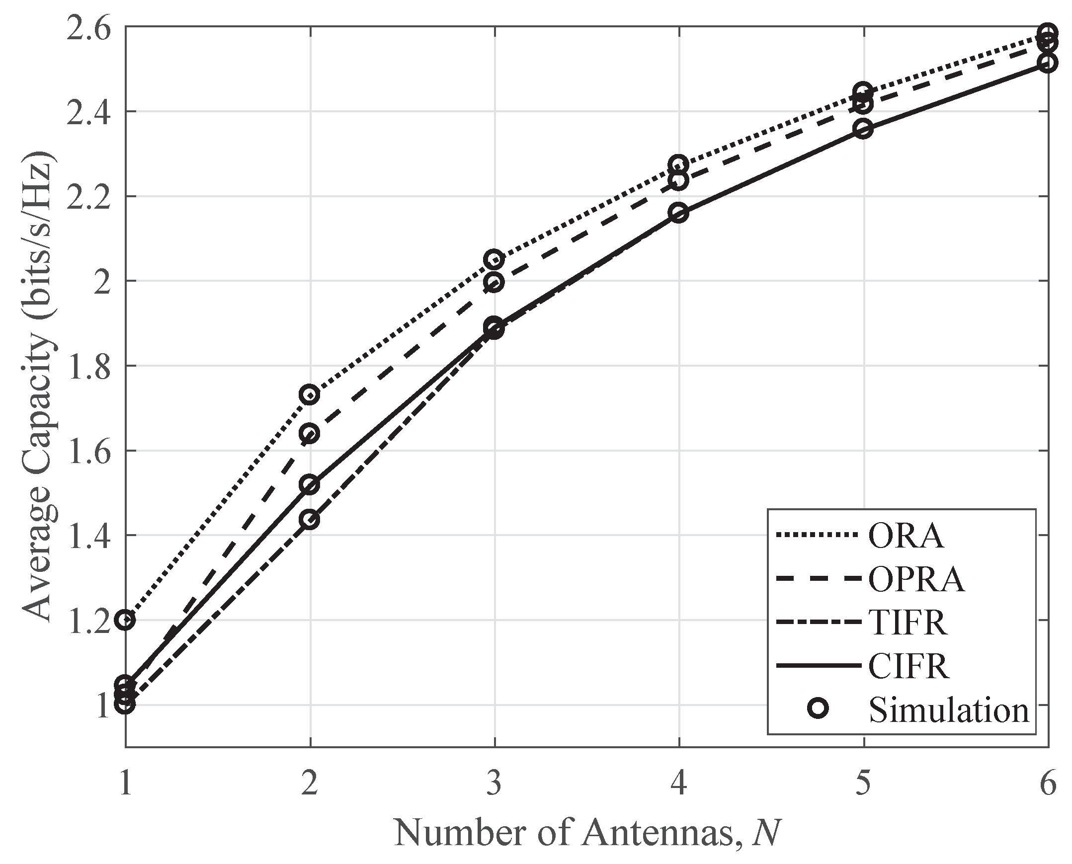
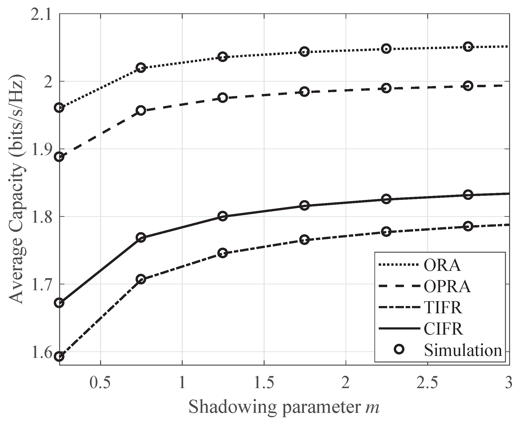
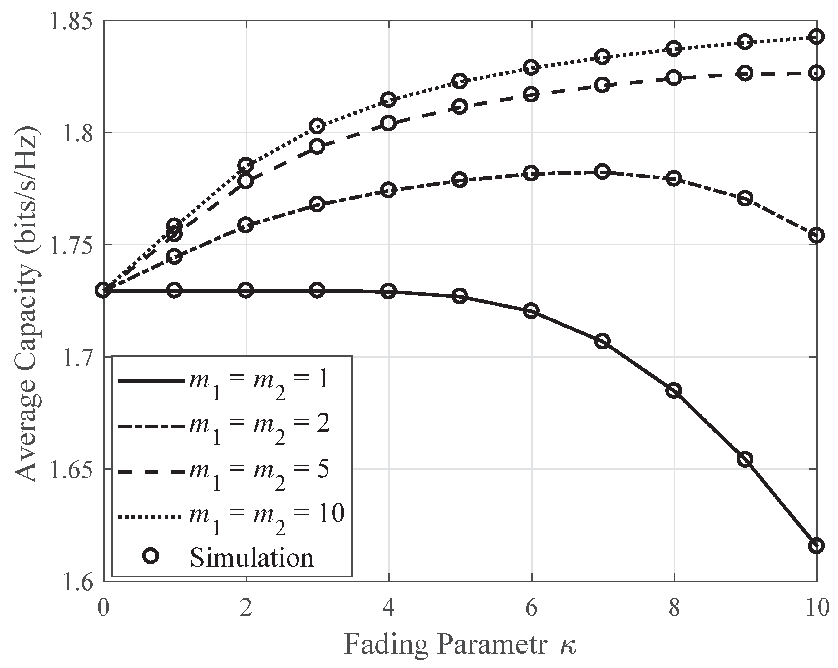
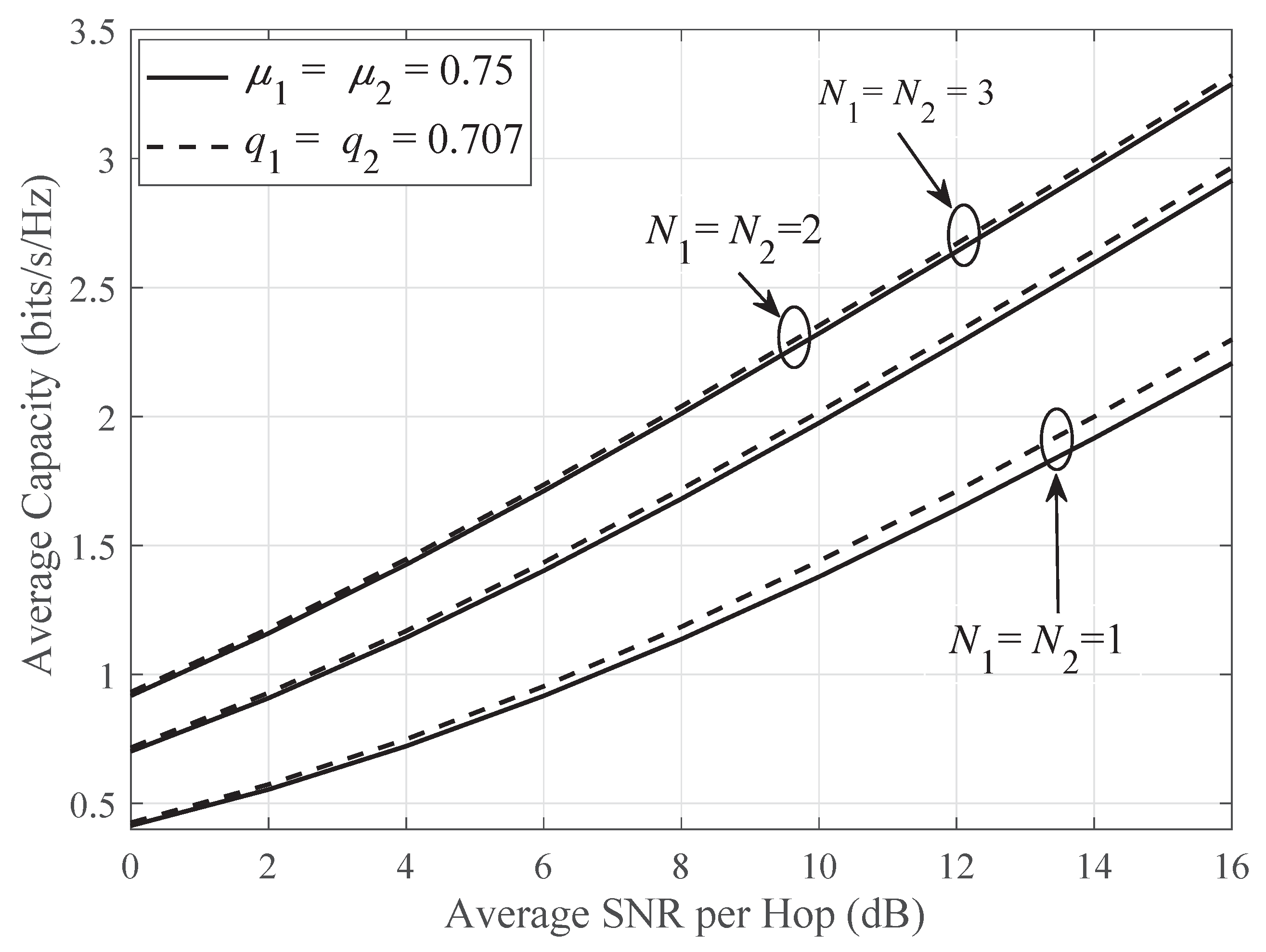
  • Using the obtained analytical results, we analyzed the system performance for various combinations of source and destination antennas and for different shadowing and fading parameters.
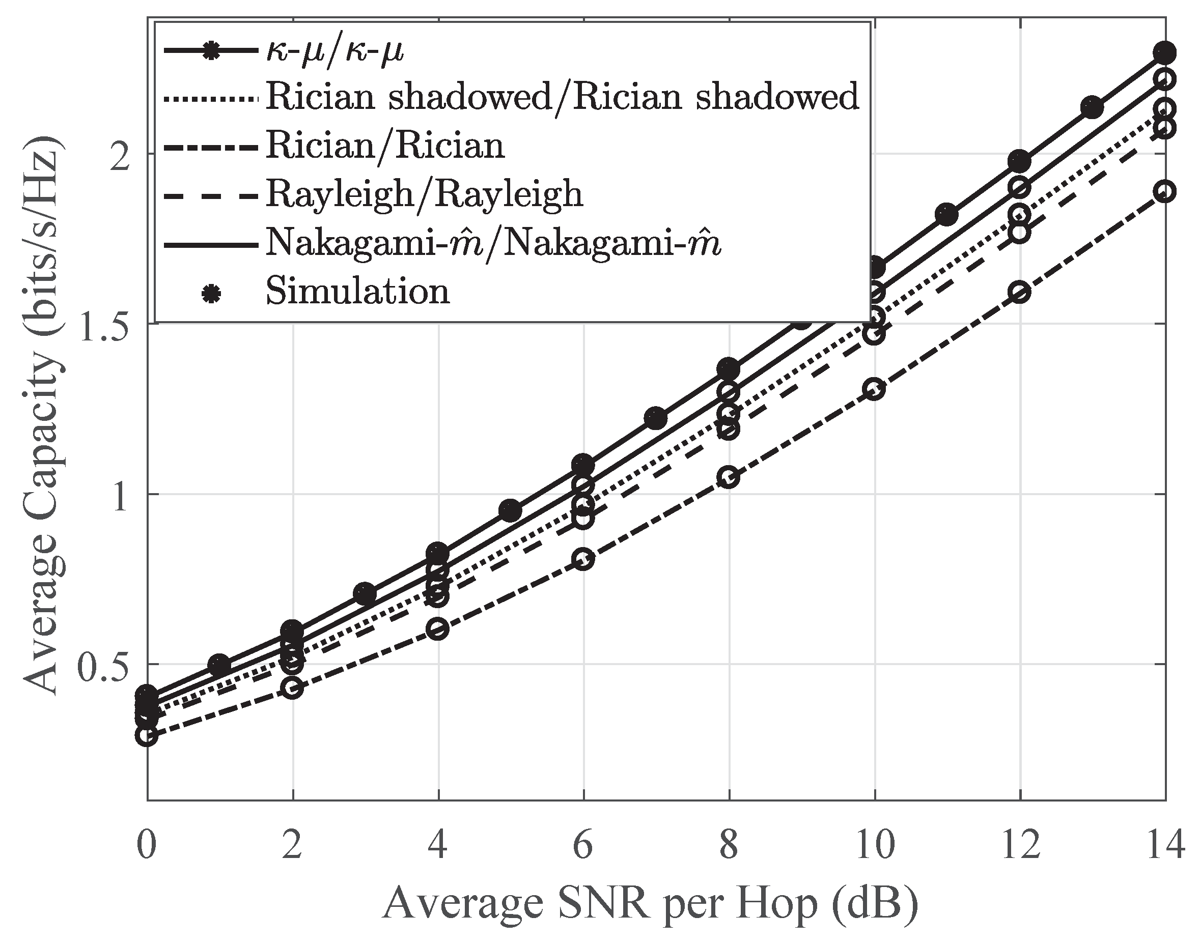
  • It should be noted that all the obtained analytical expressions are general for κ μ shadowed fading scenario, and we can therefore easily transform these expressions into some special cases, namely, Nakagami- m ^ /Nakagami- m ^ , κ μ / κ μ , Rayleigh/Rayleigh, Rician-shadowed/Rician-shadowed, Rician/Rician, and mixed Rayleigh, κ μ , Rician-shadowed, Nakagami- m ^ , and Rician fading links. These fading arrangements can occur in various applications including satellite, micro-/macro-cellular, and/or hybrid satellite/terrestrial communication systems.
  • Our results can efficiently be used to investigate the behavior of various channels like the ones in land mobile satellite systems, underwater acoustic communications, body centric communications, and other different wireless communication applications.
The rest of the paper is organized into six sections. Section 2 gives the descriptions about our considered system model and the channel model. The OP expression and average capacity expressions, which are derived using adaptive transmission techniques in the considered system, are given in Section 3. In Section 4, some special cases, obtained from our derived expressions, are discussed. The simulation results and numerical results, based on our obtained expressions in analytic form, are provided in Section 5, and finally, in Section 6, this paper is summarized and concluded.

2. System and Channel Models
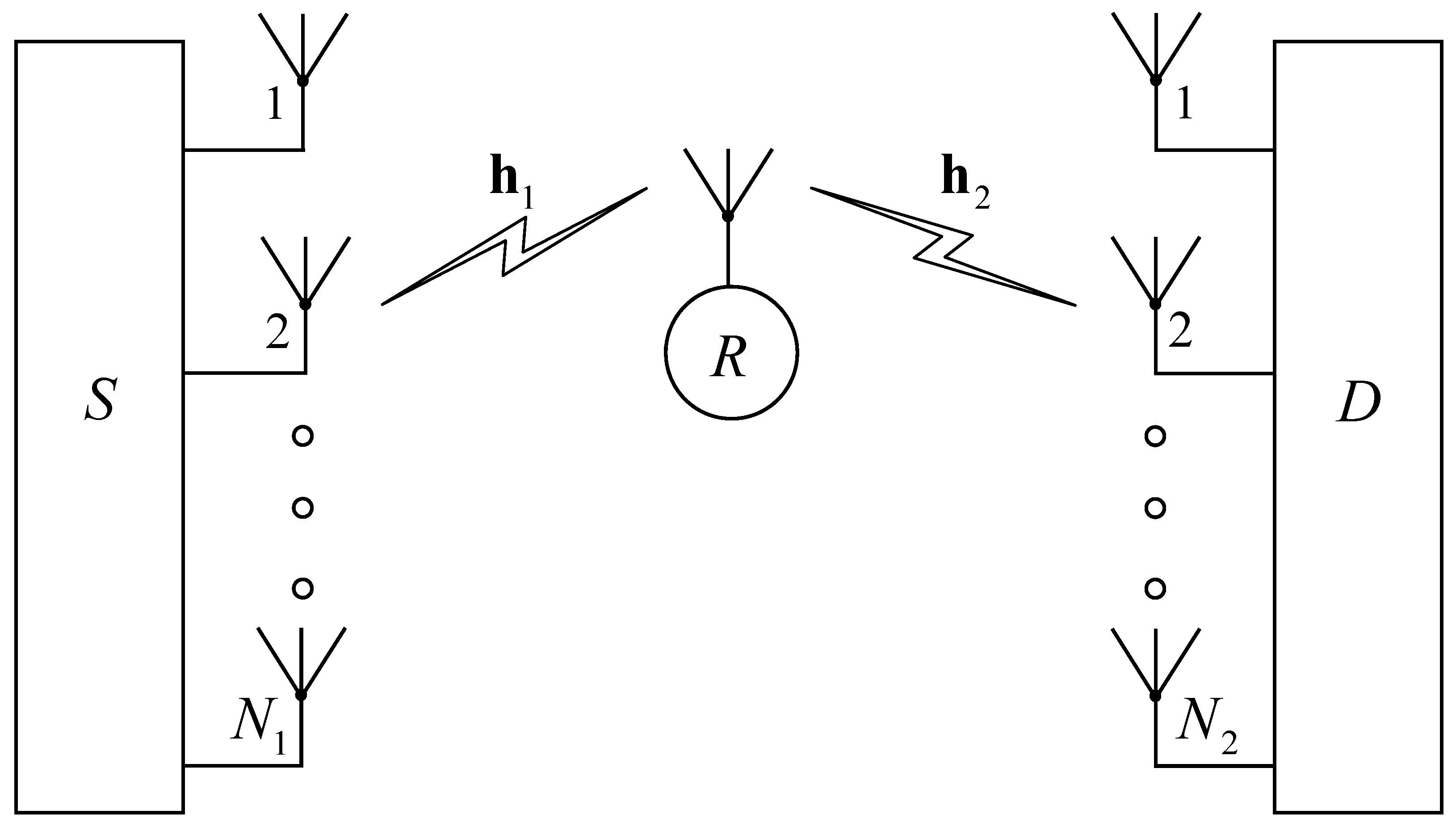
2.1. System Model

Here, a dual-hop half-duplex DF cooperative relaying system is considered, as shown in Figure 1, where a single antenna relay R assists a source S with multiple antennas N 1 to communicate with a destination D with multiple antennas N 2 . It is assumed that the CSI is available at each node. The communication from S to D is possible only through node R, and the whole transmission of a wireless signal is completed in two consecutive phases. Node S uses the maximum-ratio transmission (MRT) technique and propagates wireless signals to node R during the first phase. At node R, the collected signals are first decoded and encoded, then forwarded to node D during the next phase. The maximal-ratio combining (MRC) technique is employed at node D to aggregate all the received signals from node R. Let the channel vectors, h 1 C N 1 × 1 and h 2 C 1 × N 2 , be from S to R and from R to D links, respectively.
The total end-to-end instantaneous SNR γ t at node D is given by [45]:
γ t = min γ 1 , γ 2
where γ = | | h | | / n o ( = 1 , 2 ) represents the -th hop instantaneous SNR, with | | · | | denoting the Frobenius norm, and n o 1 and n o 2 show the average power of the additive white Gaussian noises (AWGNs) at node R and at each antenna of node D, respectively.

2.2. κ μ Shadowed Fading Model

The κμ shadowed fading model concurrently emulates both the shadowing and the multi-path fading. If κμ shadowed fading is experienced by the -th relaying hop of the relaying system, then we can write the PDF of the -th hop instantaneous SNR as [4] (Equation (3)):
f γ ( γ ) = μ ( 1 + κ ) γ ¯ N μ m m + κ μ N m 1 Γ ( N μ ) = Δ ξ γ N μ 1 exp μ ( 1 + κ ) γ ¯ = Δ ψ γ × 1 F 1 ( N m ; N μ ; κ μ 2 ( 1 + κ ) ( m + κ μ ) γ ¯ = Δ δ γ )
where Γ ( · ) designates the Gamma function, γ ¯ symbolizes the average SNR of the -th hop, κ designates the power ratio of the dominant component to the scattered waves, m denotes the shadowing parameter, and μ denotes the fading (i.e., several clusters). Additionally, 1 F 1 ( · ; · ; · ) represents the confluent hypergeometric function [46], and it is defined in the form of an infinite series as 1 F 1 ( a ; b ; z ) = i = 0 ( a ) i z i i ! ( b ) i [46] (Equation (9.210.1)), where ( z ) n = Γ ( z + n ) Γ ( z ) shows the Pochhammer symbol [46].
The κμ shadowed fading model contains the distribution of some general fading models, namely, Rician, Rician-shadowed, One-sided Gaussian, κμ, Nakagami- m ^ , and Rayleigh, as special cases [26]. Table 1 summarizes these special cases, where K and m , ^ show the fading parameters of the Rician (also for Rician-shadowed) and Nakagami- m ^ fading links, respectively.

3. Performance Analysis

The OP expression in exact analytical form of the considered system is derived first, then that for the four adaptive techniques is derived, and the new and exact average capacity expressions are also obtained.

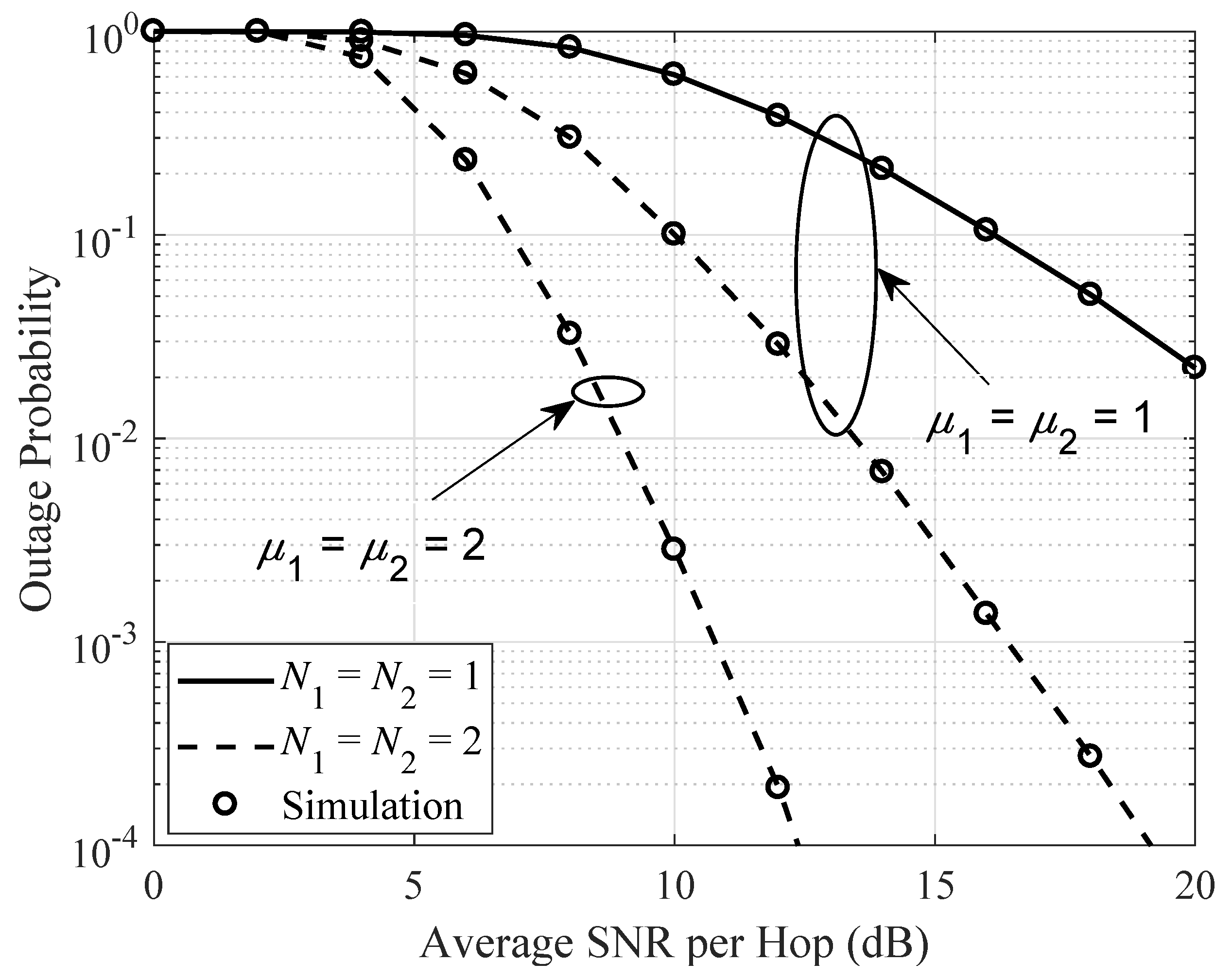
3.1. Outage Probability Analysis

In a dual-hop DF relaying system, an outage occurs when the instantaneous SNR of any hop falls down to a pre-defined value γ t h . The OP of the considered system is given by [18] (Equation (18)):
P o u t = F γ t ( γ ) = 1 P r [ γ 1 > γ ] P r [ γ 2 > γ ] = 1 γ f γ 1 ( γ ) d γ γ f γ 2 ( γ ) d γ
where f γ 1 ( γ ) and f γ 2 ( γ ) are given in Equation (2), F γ t ( γ ) is the CDF of γ t , and P r [ · ] symbolizes the probability. Using Equation (2), and with the help of [46] (Equation (3.351.2)), the integral terms of Equation (3) become:
γ f γ ( γ ) d γ = i = 0 n = 0 N μ + i 1 ξ Γ ( N m + i ) Γ ( N μ ) δ i γ n i ! n ! Γ ( N m ) ψ N μ i + n e ψ γ d γ .
Now, inserting Equation (4) into Equation (3), we obtained the OP as:
P o u t = F γ t ( γ ) = 1 i = 0 j = 0 n = 0 N 1 μ 1 + i 1 l = 0 N 2 μ 2 + j 1 ξ 1 ξ 2 Δ Π Ψ γ n + l e ( ψ 1 + ψ 2 ) γ d γ
where
Δ = Γ ( N 1 m 1 + i ) Γ ( N 1 μ 1 ) δ 1 i Γ ( N 1 m 1 ) , Π = Γ ( N 2 m 2 + j ) Γ ( N 2 μ 2 ) δ 2 j i ! j ! n ! l ! Γ ( N 2 m 2 ) , and Ψ = ψ 1 N 1 μ 1 i + n ψ 2 N 2 μ 2 j + l .
The exact OP expression in Equation (5) is presented in infinite summations, the summands decay is exponentially due to factor 1 i ! j ! n ! l ! [5]. Hence, the summations converge rapidly, with a finite number of terms. The related PDF is obtained by:
f γ t ( γ ) = 1 i = 0 j = 0 n = 0 N 1 μ 1 + i 1 l = 0 N 2 μ 2 + j 1 ξ 1 ξ 2 Δ Π Ψ d d γ γ n + l e ( ψ 1 + ψ 2 ) γ d γ = i = 0 j = 0 n = 0 N 1 μ 1 + i 1 l = 0 N 2 μ 2 + j 1 ξ 1 ξ 2 Δ Π Ψ exp ( ψ 1 γ + ψ 2 γ ) ( ψ 1 + ψ 2 ) γ n + l ( n + l ) γ n + l 1 d γ .

3.2. Capacity Analysis with Adaptive Transmission

The Shannon capacity is the maximum rate at which the information can be transmitted to the receiver, with a very small error probability, via a communication channel. In designing wireless communication systems, adaptive transmission techniques play a significant role, exploiting the channel conditions for the adaptive rate and/or transmission power. In this section, considering the most widely used adaptive transmission schemes, such as ORA, OPRA, CIFR, and TIFR, we obtain the expressions of the average capacity in analytic form.

3.2.1. Optimal Power and Rate Adaptation (OPRA)

In OPRA, the node S adapts both the transmission rate as well as the transmission power in accordance with the channel conditions. The average channel capacity using this scheme is given by [2] (Equation (17)):
C ¯ O P R A = B 2 γ o log 2 γ γ o f γ t ( γ ) d γ ,
where γ o and the parameter B denote an optimal cutoff SNR level and a channel bandwidth in Hertz, respectively. The transmission between the node S and node D is halted when the SNR level drops below the cutoff SNR level γ o . Therefore, it must satisfy [2]:
γ o γ γ o γ γ o f γ t ( γ ) d γ = 1 .
To obtain the average capacity for OPRA, C ¯ O P R A , node S and node D must have a perfect knowledge of CSI [14]. In line with the channel conditions, node S adjusts its transmit rate and transmit power, such that higher rates and powers are assigned to good channel conditions and v i c e v e r s a . In this technique, the instantaneous adaptive power and instantaneous adaptive rate, are, respectively, given by [2]:
P O P R A / P = 0 , γ < γ o 1 γ o 1 γ , γ γ o
and
R O P R A = B 2 log 2 γ γ o ,
where P designates the average power constraint. By employing the logarithmic properties, Equation (7) can be rewritten as:
C ¯ O P R A = B 2 ln ( 2 ) γ o ln ( γ ) ln ( γ o ) f γ t ( γ ) d γ .
Inserting Equation (6) into Equation (11), we have:
C ¯ O P R A = i = 0 j = 0 n = 0 N 1 μ 1 + i 1 l = 0 N 2 μ 2 + j 1 B ξ 1 ξ 2 Δ Π Ψ 2 ln ( 2 ) [ γ o ln ( γ ) γ n + l ( ψ 1 + ψ 2 ) e ( ψ 1 + ψ 2 ) γ d γ γ o ln ( γ ) γ n + l 1 ( n + l ) e ( ψ 1 + ψ 2 ) γ d γ γ o γ o γ n + l ( ψ 1 + ψ 2 ) e ( ψ 1 + ψ 2 ) γ d γ γ o γ n + l 1 ( n + l ) e ( ψ 1 + ψ 2 ) γ d γ ] .
Now, using integral relationships, [47] (Equation (A.6)) and [46] (Equation (3.381.3)), we obtained C ¯ O P R A as:
C ¯ O P R A = i = 0 j = 0 n = 0 N 1 μ 1 + i 1 l = 0 N 2 μ 2 + j 1 ξ 1 ξ 2 Δ Π Ψ B 2 ln ( 2 ) ( ψ 1 + ψ 2 ) n + l [ { ln ( γ o ) Γ n + l + 1 , ( ψ 1 + ψ 2 ) γ o + G 3 , 0 2 , 3 ( ψ 1 + ψ 2 ) γ o | 1 , 1 0 , 0 , n + l + 1 } ( n + l ) { ln ( γ o ) Γ n + l , ( ψ 1 + ψ 2 ) γ o + G 3 , 0 2 , 3 × ( ψ 1 + ψ 2 ) γ o | 1 , 1 0 , 0 , n + l } Γ n + l + 1 , ( ψ 1 + ψ 2 ) γ o ( n + l ) Γ n + l , ( ψ 1 + ψ 2 ) γ o ]
where G . , . . , . [ · ] and Γ ( · , · ) are the Meijer G-function [46] (Sec. 9.3) and upper incomplete gamma function [46], respectively.

3.2.2. Optimal Rate Adaptation with Constant Transmit Power (ORA)

In the ORA technique, node S only alters its transmission rate with the variations of the total end-to-end SNR. The average channel capacity using this scheme is given by [2] (Equation (24)):
C ¯ O R A = B 2 ln ( 2 ) 0 ln ( 1 + γ ) f γ t ( γ ) d γ .
Plugging Equation (6) into Equation (14), we obtain:
C ¯ O R A = i = 0 j = 0 n = 0 N 1 μ 1 + i 1 l = 0 N 2 μ 2 + j 1 ξ 1 ξ 2 Δ Π Ψ B 2 ln ( 2 ) × ( ψ 1 + ψ 2 ) 0 ln ( 1 + γ ) γ n + l e ( ψ 1 + ψ 2 ) γ d γ ( n + l ) 0 ln ( 1 + γ ) γ n + l 1 e ( ψ 1 + ψ 2 ) γ d γ .
Furthermore, solving the integrals of Equation (15) with the help of [47] (Equation (A.3)), one can obtain the average channel capacity using the considered technique as:
C ¯ O R A = i = 0 j = 0 n = 0 N 1 μ 1 + i 1 l = 0 N 2 μ 2 + j 1 ξ 1 ξ 2 Δ Π Ψ B 2 ln ( 2 ) e ( ψ 1 + ψ 2 ) ( ψ 1 + ψ 2 ) n + l [ p = 0 n + l Γ p , ( ψ 1 + ψ 2 ) × ( ψ 1 + ψ 2 ) p Γ ( n + l + 1 ) q = 0 n + l 1 Γ q , ( ψ 1 + ψ 2 ) Γ ( n + l ) ( n + l ) ( ψ 1 + ψ 2 ) q ] .

3.2.3. Channel Inversion with Fixed Rate (CIFR)

The CIFR technique alters the transmission power at node S to sustain a constant SNR level of the system, with the fixed rate modulation and the fixed-code design. The average capacity of the CIFR technique employed in this scheme can be written as [2] (Equation (28)):
C ¯ C I F R = B 2 log 2 1 + 0 1 γ f γ t ( γ ) d γ 1 .
Plugging Equation (6) into Equation (17), we have:
C ¯ C I F R = log 2 2 i = 0 j = 0 n = 0 N 1 μ 1 + i 1 l = 0 N 2 μ 2 + j 1 ξ 1 ξ 2 B Δ Π Ψ × 1 + 0 ( ψ 1 + ψ 2 ) γ n + l e ( ψ 1 + ψ 2 ) γ d γ 0 ( n + l ) γ n + l 1 e ( ψ 1 + ψ 2 ) γ d γ 1 .
Now, solving the integral, with the help of [46] (Equation (3.351.3)), we obtain the average capacity as:
C ¯ C I F R = log 2 2 i = 0 j = 0 n = 0 N 1 μ 1 + i 1 l = 0 N 2 μ 2 + j 1 ξ 1 ξ 2 B Δ Π Ψ 1 + ( ψ 1 + ψ 2 ) n + l Γ ( n + l + 1 ) ( n + l ) Γ ( n + l ) .
In CIFR, the degradation of the transmission capacity occurs because it maintains a fixed rate, regardless of the channel condition. A modified channel inversion technique, called truncated channel inversion with fixed rate, is used to improve this capacity loss. In TIFR, the fading channel is inverted when the total SNR from node S to node D rises above the predetermined threshold SNR γ o . The channel capacity using the TIFR scheme is derived by [2]:
C ¯ T I F R = B 2 log 2 1 + 1 γ o 1 γ f γ t ( γ ) d γ 1 P o u t .
The exact analytical expression for the channel capacity using this technique can be derived by inserting Equation (6) into Equation (21), which gives:
C ¯ T I F R = log 2 2 i = 0 j = 0 n = 0 N 1 μ 1 + i 1 l = 0 N 2 μ 2 + j 1 ξ 1 ξ 2 B Δ Π Ψ × 1 + γ o ( ψ 1 + ψ 2 ) γ n + l 1 e ( ψ 1 + ψ 2 ) γ d γ γ o ( n + l ) γ n + l 2 e ( ψ 1 + ψ 2 ) γ d γ 1 1 P o u t .
Now, solving the integral, with the aid of [46] (Equation (3.351.2)), we obtain:
C ¯ T I F R = log 2 2 i = 0 j = 0 n = 0 N 1 μ 1 + i 1 l = 0 N 2 μ 2 + j 1 ξ 1 ξ 2 B Δ Π Ψ × 1 + Γ n + l , ( ψ 1 + ψ 2 ) γ o ( n + l ) Γ n + l 1 , ( ψ 1 + ψ 2 ) γ o ( ψ 1 + ψ 2 ) n + l 1 1 ( 1 P o u t ) .

4. Special Cases

As discussed above, the κμ shadowed fading model contains some known fading models, namely, Rician, Rician-shadowed, κμ, Nakagami- m ^ , and Rayleigh fading, as special cases [26]. Owing to these special cases, our obtained expressions in analytic form are general, and we can reduce them into asymmetric and symmetric fading conditions. For the sake of brevity, different scenarios, for asymmetric and symmetric fading conditions, are summarized in Table 2. We discuss special cases and the relation between previous works and new contributions for the outage probability and average capacity using adaptive transmission techniques in the following subsections.

4.1. Special Cases for Outage Probability Analysis

The obtained analytical results for the κμ/κμ, κμ/Rician, κμ/Nakagami- m ^ , κμ/Rayleigh, Rician/κμ, Rician/Nakagami- m ^ , Rician/Rayleigh, Nakagami- m ^ /Nakagami- m ^ , Nakagami- m ^ /κμ, Nakagami- m ^ /Rician, Nakagami- m ^ /Rayleigh, Rayleigh/Rayleigh, Rayleigh/κμ, Rayleigh/Rician, and Rayleigh/Nakagami- m ^ fading links given in Table 2 are already reported in [45].
The remaining derived analytical results given in Table 2 for the κμ shadowed/κμ, κμ shadowed/Rician-shadowed, κμ shadowed/Rician, κμ shadowed/Nakagami- m ^ , κμ shadowed/Rayleigh, κμ/κμ shadowed, κμ/Rician-shadowed, Rician-shadowed/Rician-shadowed, Rician-shadowed/κμ shadowed, Rician-shadowed/κμ, Rician-shadowed/Rician, Rician-shadowed/Nakagami- m ^ , Rician-shadowed/Rayleigh, Rician/κμ shadowed, Rician/Rician-shadowed, Nakagami- m ^ /κμ shadowed, Nakagami- m ^ /Rician-shadowed, Rayleigh/κμ shadowed, and Rayleigh/Rician-shadowed fading links are new in the literature.

4.2. Special Cases for Average Capacity Analysis

In Table 2, all obtained special cases for the average capacity using adaptive transmission techniques are not found to be reported in any literature.

5. Numerical Results and Discussions

In κμ shadowed fading environments, we evaluated the system performance of a dual-hop DF relaying system with beamforming using adaptive transmission techniques.
The obtained analytical results (i.e., Equations (3), (13), (16), (19) and (22)) closely match with the results from the Monte Carlo simulations (where, each simulation point is average of 2 × 10 8 runs). Moreover, the expressions in analytic form are presented by an infinite expression of the form, which converges rapidly with several terms and are evaluated numerically. The infinite summations are truncated up to three decimal places and we used the numerical computation to ensure correctness.
Figure 2 shows the outage performance with respect to the average SNR per hop ( γ ¯ = γ ¯ 1 = γ ¯ 2 ) for various antenna numbers ( N 1 and N 2 ) and for different parameter values of μ ( μ 1 , μ 2 ). Figure 2 confirms that the numerical results obtained from Equation (5) are perfectly consistent with the simulation results. The fading parameter μ and the number of antennas have a positive relationship with the system performance. Therefore, as expected, the system performance was improved with the fading parameter μ and the number of antennas.
In Figure 3, the average channel capacity is presented against the average SNR per hop using four adaptive transmission approaches, such as ORA, OPRA, CIFR, and TIFR. It can be observed that the analytical and the simulation results are closely matching with each other. Generally, the ORA technique performs well, as compared to the other techniques. In a high SNR regime, the ORA and OPRA techniques have an equivalent capacity performance. To improve the quality of links, the OPRA policy uses more transmit power, whereas the ORA policy only adapts its rate. Therefore, the ORA technique has a lower complexity, as compared to the OPRA technique. The CIFR technique performs poorly in the low and medium average SNR regions, when compared to the other techniques. However, in a high SNR regime, it attains the same capacity performance as TIFR.
Figure 4 exhibits the average channel capacity of the OPRA technique against the average SNR per hop for the distinct channel models, viz., the Rician/Rician, κμ/κμ, Rayleigh/Rayleigh, Rician-shadowed/Rician-shadowed, and Nakagami- m ^ /Nakagami- m ^ fading links. As discussed before, the generalized κμ shadowed fading model contains these channel models as special cases, as listed in Table 2. Note that the parameter m ( m 1 , m 2 ) is set as m 1 = m 2 = 100 for non-shadowing environments, m 1 = m 2 = 0.5 for shadowing environments, and the accuracy is confirmed through simulation. Furthermore, it is clear, from Figure 4, that κμ/κμ outperforms the other fading models, whereas the Rician/Rician shows the lowest performance, owing to shadowing.
In Figure 5, the capacity performance is shown with respect to the number of antennas. We notice that the capacity performance increases with the increasing number of antennas at S and D nodes for all adaptive policies. It can also be seen that the ORA policy obtains a larger capacity, as compared to OPRA, when the number of antennas is low, but the performance gap between ORA and OPRA reduces with the increasing number of antennas. Additionally, a gap in the capacities of the TIFR and CIFR techniques is also observed with a lower number of antennas, but it is unnoticeable when the number of antennas is increased.
Figure 6 shows the average channel capacity for the parameter, m ( m 1 , m 2 ) , in the considered environment of κμ shadowed fading. It can be noticed that the capacity performance improves with the increasing value of the parameter m. The shadowing parameter m is the degree of fluctuation in the dominant component of the signal, owing to shadowing. For the larger parameter m, the power of the dominant component is more stable and thus causes less shadowing.
Figure 7 exhibits the average channel capacity of the ORA technique as a function of the fading parameter κ ( κ 1 , κ 2 ) for the different shadowing parameter m. An improvement in the system performance is observed for the higher value of m (i.e., light shadowing conditions), as compared to the smaller value of m (i.e., strong shadowing conditions). Additionally, the capacity performance decreases in a strong shadowing environment as κ increases and v i c e v e r s a .
The κμ shadowed distribution contains Nakagami- m ^ distribution as a particular case (when κ 0 , μ = m ^ , and m ). It is known that the Hoyt (Nakagami-q) distribution can be approximated by the Nakagami- m ^ distribution by setting a relation between the Nakagami-q parameter q and the Nakagami- m ^ parameter m ^ , as m = ( 1 + q 2 ) 2 / 2 ( 1 + 2 q 4 ) when m 1 [48] (Equation (2.25)). Thus, the κμ shadowed distribution can also approximate the Nakagami-q distribution, and the equivalence notion between the parameters can be written as:
μ = ( 1 + q 2 ) 2 2 ( 1 + 2 q 4 ) , for κ 0 , μ 1 , and m .
In Figure 8, we investigate the equivalence notion in the capacity performance of the considered system. We set the parameter values as μ = 0.75 and q = 0.707 for the κμ shadowed links and Nakagami-q fading links, respectively, which satisfies Equation (23). Figure 8 shows the capacity performance of the ORA technique against the κμ shadowed fading links (when μ 1 = μ 2 = 0.75 ) and its analogous counterpart Nakagami-q fading links (when q 1 = q 2 = 0.707 ). The channel capacity for κμ shadowed fading is obtained from Equation (16), whereas, for the Nakagami-q fading, it is obtained from the simulation. It is observed that the performance difference is greater when each node is equipped with a single antenna, whereas this performance gap reduces when the number of antennas increase. For instance, when the system is operating over κμ shadowed fading links and its equivalent Nakagami-q fading links for N 1 = N 2 = 1 , at an average SNR per hop of 14 dB, a difference in the capacity of 0.083 dB is obtained, while a smaller difference in the capacity of 0.033 dB is obtained when N 1 = N 2 = 3 .

6. Conclusions

In this paper, a dual-hop DF relaying system was studied using different adaptive transmission techniques, where multiple antennas were only employed at the S and D nodes. The system performance for different adaptive techniques were evaluated for κμ shadowed fading channels. The new and exact analytical expressions for the OP and average capacity using the ORA, OPRA, TIFR, and CIFR techniques were obtained. With the aid of the obtained analytic expressions, the performance was analyzed for different parameters, such as shadowing (i.e, m 1 and m 2 ), fading (i.e., κ and μ ), and the number of antennas (i.e., N 1 and N 2 ). The parameter μ and number of antennas have a positive relationship with the system performance. The ORA technique performs better, as compared to the OPRA, CIFR, and TIFR techniques. The improvement in the capacity performance is observed under light shadowing conditions (larger m) than under strong shadowing conditions (lower m). Additionally, the capacity performance decreases in a strong shadowing environment as κ increases, and v i c e v e r s a . The main contribution of our paper was to derive new and exact analytical expressions in the general form for a dual-hop DF relaying system with beamforming using adaptive transmission techniques, therefore, the derived analytical results are useful for evaluating system performance under different fading and shadowing environments. Our results are helpful to system design in the sense that the system performance can efficiently be analyzed for arbitrary system parameters without any need for an extensive and complex Monte Carlo simulation.

Author Contributions

Z.B. carried out formal analysis, provided the research methodology, performed numerical analysis and Monte Carlo simulations of the proposed system model, W.Y. supervised and reviewed the manuscript.

Funding

This work was supported by the Dong-A University Research Fund.

Acknowledgments

The authors extend their gratitude to the anonymous reviewers for their valuable and constructive comments, which helped us to improve the quality this manuscript.

Conflicts of Interest

The authors declare no conflicts of interest.

References

  1. Baki, A.K.M.; Absar, M.W.; Rehman, T.; Ahamed, K.M.A. Investigation of Rayleigh and Rician Fading Channels for State of the Art (SOA) LTE-OFDM Communication System. In Proceedings of the 4th International Conference on Advances in Electrical Engineering (ICAEE), Dhaka, Bangladesh, 28–30 September 2017. [Google Scholar]
  2. Kumar, R.; Aziz, A.; Joe, I. Opportunistic Relaying Analysis using Antenna Selection under Adaptive Transmission. IEICE Trans. Commun. 2016, E99-B, 2435–2441. [Google Scholar] [CrossRef]
  3. Hussain, A.; Kim, S.H.; Chang, S.H. On the Performance of Dual-Hop Variable-Gain AF Relaying with Beamforming over η-μ Fading Channels. IEICE Trans. Commun. 2017, E100-B, 619–626. [Google Scholar] [CrossRef]
  4. Hussain, A.; Kim, S.H.; Chang, S.H. Dual-hop Variable-Gain AF Relaying with Beamforming over κμ Shadowed Fading Channels. In Proceedings of the 2016 IEEE Global Communications Conference (GLOBECOM), Washington, DC, USA, 4–8 December 2016. [Google Scholar]
  5. Hussain, A.; Lee, K.; Kim, S.H.; Chang, S.H.; Kim, D.I. Performance Analysis of Dual-hop Variable-Gain Relaying with Beamforming over κμ Fading Channels. IET Commun. 2017, 11, 1587–1593. [Google Scholar] [CrossRef]
  6. Tran, T.; Voznak, M. Multi-Points Cooperative Relay in NOMA System with N-1 DF Relaying Nodes in HD/FD Mode for N User Equipments with Energy Harvesting. Electronics 2019, 8, 167. [Google Scholar] [CrossRef]
  7. Ai, Y.; Cheffena, M. On Multi-Hop Decode-and-Forward Cooperative Relaying for Industrial Wireless Sensor Networks. Sensors 2017, 17, 695. [Google Scholar] [CrossRef] [PubMed]
  8. Nyarko, J.K.N.; Mbom, C.A. A Performance Study of Massive MIMO Heterogeneous Networks with Ricean/Rayleigh Fading. Electronics 2018, 7, 79. [Google Scholar] [CrossRef]
  9. Nechiporenko, T.; Phan, K.T.; Tellambura, C.; Nguyen, H.H. On the Capacity of Rayleigh Fading Cooperative Systems under Adaptive Transmission. IEEE Trans. Wirel. Commun. 2009, 8, 1626–1631. [Google Scholar] [CrossRef]
  10. Nguyen, B.Q.; Doung, T.Q.; Tran, N.N. Ergodic Capacity of Cooperative Networks using Adaptive Transmission and Selection Combining. In Proceedings of the 3rd International Conference on Signal Processing and Communication Systems (ICSPCS), Omaha, NE, USA, 28–30 September 2009. [Google Scholar]
  11. Ikki, S.S.; Ahmed, M.H. On the Capacity of Relay-Selection Cooperative-Diversity Networks under Adaptive Transmission. In Proceedings of the 72nd IEEE Vehicular Technology Conference (VTC), Ottawa, ON, Canada, 6–9 September 2010. [Google Scholar]
  12. Torabi, M.; Haccoun, D.; Frigon, J.F. On the Performance of AF Opportunistic Relaying with Adaptive Transmission over Rayleigh Fading Channels. In Proceedings of the 2011 IEEE Pacific Rim Conference on Communications, Computers and Signal Processing, Victoria, BC, Canada, 22–24 August 2011. [Google Scholar]
  13. Kong, H.Y.; Bao, V.N. Capacity Analysis of Opportunistic Cooperative Networks under Adaptive Transmission over Rayleigh Fading Channels. Wirel. Pers. Commun. 2006, 62, 411–430. [Google Scholar] [CrossRef]
  14. Torabi, M.; Haccoun, D. Capacity of Amplify-and-Forward Selective Relying with Adaptive Transmission under Outdated Channel Information. IEEE Trans. Veh. Technol. 2011, 60, 2416–2422. [Google Scholar] [CrossRef]
  15. Torabi, M.; Haccoun, D.; Frigon, J.F. Impact of Outdated Relay Selection on the Capacity of AF Opportunistic Relaying Systems with Adaptive Transmission over Non-Identically Distributed Links. IEEE Trans. Wirel. Commun. 2011, 10, 3626–3631. [Google Scholar] [CrossRef]
  16. Kim, S.; Lee, S.; Lee, H.; Hong, D. Capacity Analysis of Outdated Relay Selection in Opportunistic Relaying System using an Adaptive Transmission Technique. In Proceedings of the 2014 IEEE Wireless Communications and Networking Conference (WCNC), Istanbul, Turkey, 3–6 April 2014. [Google Scholar]
  17. Zhong, B.; Zhang, X.; Li, Y.; Zhang, Z.; Long, K. Impact of Partial Relay Selection on the Capacity of Communications Systems with Outdated CSI and Adaptive Transmission Techniques. In Proceedings of the 2013 IEEE Wireless Communications and Networking Conference (WCNC), Shanghai, China, 7–10 April 2013. [Google Scholar]
  18. Bhatnagar, M.R. On the Capacity of Decode-and-Forward Relaying over Rician Fading Channels. IEEE Commun. Lett. 2013, 17, 1100–1103. [Google Scholar] [CrossRef] [Green Version]
  19. Modi, B.; Olabiyi, O.; Annamalai, A.; Vaman, D. On Ergodic Capacity of Cooperative Non-regenerative Relay Networks in Rice Fading Environments. In Proceedings of the IEEE Global Communications Conference, Houston, TX, USA, 5–9 December 2011. [Google Scholar]
  20. Modi, B.; Annamalai, A.; Olabiyi, O.; Palat, R.C. Ergodic Capacity Analysis of Cooperative Amplify-and-Forward Relay Networks over Rice and Nakagami Fading Channels. Int. J. Wirel. Mob. Netw. 2012, 14, 97–116. [Google Scholar] [CrossRef]
  21. Modi, B.; Annamalai, A.; Olabiyi, O.; Palat, R.C. Ergodic Capacity Analysis of Cooperative Amplify-and-Forward Relay Networks over Generalized Fading Channels. Wirel. Commun. Mob. Comput. 2015, 15, 1259–1273. [Google Scholar] [CrossRef]
  22. Phan, H.; Duong, T.Q.; Zepernick, H.J.; Shu, L. Adaptive Transmission in MIMO AF Relay Networks with Orthogonal Space-Time Block Codes over Nakagami-m Fading. EURASIP J. Wirel. Commun. Netw. 2011, 2012, 1–13. [Google Scholar] [CrossRef]
  23. Torabi, M.; Frigon, J.F.; Haccoun, D. Adaptive Transmission in Amplify-and-Forward Cooperative Communications using Orthogonal Space-Time Block Codes under Spatially Correlated Antennas. IET Commun. 2015, 9, 1683–1690. [Google Scholar] [CrossRef]
  24. Thanh, T.L.; Bao, V.N.Q.; Duy, T.T. Capacity Analysis of Multi-Hop Decode-and-Forward over Rician Fading Channels. In Proceedings of the 2014 International Conference on Computing, Management and Telecommunications (ICCMT), Da Nang, Vietnam, 27–29 April 2014. [Google Scholar]
  25. Farhadi, G.; Beaulieu, N.C. Capacity of Amplify-and-Forward Multi-Hop Relaying Systems under Adaptive Transmission. IEEE Trans. Commun. 2010, 58, 758–763. [Google Scholar] [CrossRef]
  26. Pairs, J.F. Statistical Characterization of κμ Shadowed Fading. IEEE Trans. Veh. Technol. 2014, 63, 518–526. [Google Scholar] [CrossRef]
  27. Corrales, C.G.; Canete, F.J.; Paris, J.F. Capacity of κμ Shadowed Fading Channels. Int. J. Antennas Propag. 2014, 2014, 1–8. [Google Scholar] [CrossRef]
  28. Martinez, F.J.; Paris, J.F.; Jerez, J.M. The κμ Shadowed Fading Model with Integer Fading Parameters. IEEE Trans. Veh. Technol. 2017, 66, 7653–7662. [Google Scholar] [CrossRef]
  29. Kumar, S. Approximate Outage Probability and Capacity for κμ Shadowed Fading. IEEE Wirel. Commun. Lett. 2015, 4, 301–304. [Google Scholar] [CrossRef]
  30. Aloqlah, M.S.; Atawi, M.S.; Mistarihi, M.F. On the Performance of Fixed Gain Amplify-and-Forward Dual-hop Relay Systems with Beamforming under κμ Shadowed Fading. In Proceedings of the IEEE Annual International Symposium on Personal, Indoor, and Mobile Radio Communications (PIMRC), Hongkong, China, 30 August–2 September 2015. [Google Scholar]
  31. Arti, M.K. Beamforming and Combining Based Scheme over κμ Shadowed Fading Satellite Channels. IET Commun. 2016, 10, 1–9. [Google Scholar]
  32. Zhang, J.; Li, X.; Ansari, I.S.; Liu, Y.; Qaraqe, K.A. Performance Analysis of Dual-Hop DF Satellite Relaying over κμ Shadowed Fading. In Proceedings of the 2017 IEEE Wireless Communications and Networking Conference (WCNC), San Francisco, CA, USA, 19–22 March 2017. [Google Scholar]
  33. Hussain, A.; Kim, S.H.; Chang, S.H. Nonlinear Energy-Harvesting Relaying with Beamforming and Hardware Impairments in κμ Shadowed Fading Environment. Trans. Emerg. Telecommun. Technol. 2018, 29, e3303. [Google Scholar] [CrossRef]
  34. Ferdinand, N.S.; Rajatheva, N. Unified Performance Analysis of Two-Hop Amplify-and-Forward Relay Systems with Antenna Correlation. IEEE Trans. Wirel. Commun. 2011, 10, 3002–3011. [Google Scholar] [CrossRef]
  35. Costa, D.B.; Aissa, S. Beamforming in Dual-Hop Fixed Fain Relaying Systems. In Proceedings of the 2009 IEEE International Conference on Communications (ICC), Dresden, Germany, 14–18 June 2009. [Google Scholar]
  36. Costa, D.B.; Aissa, S. Cooperative Dual-Hop Relaying Systems with Beamforming over Nakagami-m Fading channels. IEEE Trans. Wirel. Commun. 2009, 8, 3950–3954. [Google Scholar] [CrossRef]
  37. Yang, N.; Elkashlan, M.; Yuan, J.; Shen, T. On the SER of Fixed Gain Amplify-and-Forward Relaying with Beamforming in Nakagami-m Fading. IEEE Commun. Lett. 2010, 14, 942–944. [Google Scholar] [CrossRef]
  38. Lin, M.; An, K.; Ouyang, J.; Huang, Y.; Li, M. Effect of Beamforming on Multi-Antenna Two hop Asymmetric Fading Channels with Fixed Gain Relays. Prog. Electron. Res. 2013, 133, 367–390. [Google Scholar] [CrossRef]
  39. Badarneh, O.S.; Mesleh, R. Cooperative Dual-Hop Wireless Communication Systems with Beamforming over η-μ Fading Channels. IEEE Trans. Veh. Technol. 2016, 65, 37–46. [Google Scholar] [CrossRef]
  40. Louie, R.H.Y.; Li, Y.; Vucetic, B. Performance Analysis of Beamforming in Two-Hop Amplify-and-Forward Relay Networks. In Proceedings of the 2008 IEEE International Conference on Communications (ICC), Beijing, China, 19–23 May 2008. [Google Scholar]
  41. Louie, R.H.Y.; Li, Y.; Vucetic, B. Performance Analysis of Beamforming in Two-Hop Amplify-and-Forward Relay Networks with Antenna Correlation. IEEE Trans. Wirel. Commun. 2009, 8, 3132–3141. [Google Scholar] [CrossRef]
  42. Duong, T.Q.; Zepernick, H.J.; Bao, V.N.Q. Symbol Error Probability of Hop-by-Hop Beamforming in Nakagami-m Fading. Electron. Lett. 2009, 45, 1042–1044. [Google Scholar] [CrossRef]
  43. Chen, S.; Liu, F.; Zhang, X.; Han, Y.; Yang, D. On the Performance of Two-Hop Amplify-and-Forward Relay Networks with Beamforming over Rayleigh-Rician Fading Channels. In Proceedings of the 72nd IEEE Vehicular Technology Conference (VTC), Ottawa, ON, Canada, 6–9 September 2010. [Google Scholar]
  44. Miridakis, N.I.; Vergados, D.D.; Michalas, A. Dual-Hop Communication over a Satellite Relay and Shadowed Rician Channels. IEEE Trans. Veh. Technol. 2015, 64, 4031–4040. [Google Scholar] [CrossRef]
  45. Kumar, R.; Aziz, A.; Joe, I. Cooperative Dual-Hop Decode-and-Forward Relaying with Beamforming over κμ Fading Channels. J. Next Gen. Technol. 2016, 7, 38–49. [Google Scholar]
  46. Gradshteyn, I.S.; Ryzhik, I.M. Table of Integrals, Series, and Products, 7th ed.; Academic Press: San Diego, CA, USA, 2007. [Google Scholar]
  47. Vagenas, E.D.; Karadimas, P.; Kotsopoulos, S.A. Ergodic Capacity for the SIMO Nakagami-m Channel. EURASIP J. Wirel. Commun. Netw. 2009, 2009, 1–9. [Google Scholar] [CrossRef]
  48. Simon, M.K.; Alouini, M.-S. Digital Communication over Fading Channels, 2nd ed.; John Wiley & Sons: Hoboken, NJ, USA, 2000. [Google Scholar]
Figure 1. Dual-hop DF relaying system with beamforming.
Electronics 08 00658 g001
Figure 2. Outage probability against average SNR per hop for different arrangements of antenna and fading parameter μ when κ 1 = κ 2 = 1 , m 1 = m 2 = 2 , and γ t h = 10 dB.
Electronics 08 00658 g002
Figure 3. Average channel capacity for four different adaptive transmission methods with respect to the average SNR per hop when m 1 = m 2 = 0 . 5 , μ 1 = μ 2 = 1 , κ 1 = κ 2 = 1 , and N 1 = N 2 = 2 .
Electronics 08 00658 g003
Figure 4. Average channel capacity of OPRA scheme for some channel models, viz., the Rician (when K 1 = K 2 = 5 ), κ μ (when κ 1 = κ 2 = 4 and μ 1 = μ 2 = 2 ), Rician-shadowed (when K 1 = K 2 = 8 and m 1 = m 2 = 0 . 5 ), Rayleigh fading, and Nakagami- m ^ (when the shaping factor of the Nakagami- m ^ is set to 2 for each link).
Electronics 08 00658 g004
Figure 5. Average channel capacity of four adaptive transmission policies for different arrangements of antennas, N ( N 1 , N 2 ), when γ ¯ 1 = γ ¯ 2 = 8 dB, κ 1 = κ 2 = 1 , μ 1 = μ 2 = 1 , and m 1 = m 2 = 1 .
Electronics 08 00658 g005
Figure 6. Average channel capacity under different adaptive transmission techniques for different shadowing parameter, m ( m 1 , m 2 ) , when γ ¯ 1 = γ ¯ 2 = 10 , N 1 = N 2 = 2 , κ 1 = κ 2 = 1 , and μ 1 = μ 2 = 1 .
Electronics 08 00658 g006
Figure 7. Average channel capacity of ORA technique with respect to the fading parameter κ ( κ 1 , κ 2 ) for different shadowing parameter m when γ ¯ = 8 dB, μ 1 = μ 2 = 1 , and N 1 = N 2 = 2 .
Electronics 08 00658 g007
Figure 8. Average channel capacity using ORA technique of dual-hop relaying systems operating over κ μ shadowed fading links and its equivalent Nakagami-q fading links for different number of antennas.
Electronics 08 00658 g008
Table 1. Special cases obtained from the κ μ shadowed distribution [26,33].
Fading Distribution κ μ m
Rician shadowed κ = K μ = 1 m = m
Nakagami- m ^ κ 0 μ = m ^ m
κ μ κ = κ μ = μ m
Rician κ = K μ = 1 m
Rayleigh κ 0 μ = 1 m
One-sided Gaussian κ 0 μ = 0 . 5 m
Table 2. Special cases obtained from general analyses for κ μ shadowed fading channels with different parameter settings [33].
First Hop/Second Hop κ 1 μ 1 κ 2 μ 2 m 1 m 2
κ μ shadowed/ κ μ κ 1 μ 1 κ 2 μ 2 m 1
κ μ shadowed/Rician-shadowed κ 1 μ 1 K 2 1 m 1 m 2
κ μ shadowed/Rician κ 1 μ 1 K 2 1 m 1
κ μ shadowed/Nakagami- m ^ κ 1 μ 1 0 m ^ 2 m 1
κ μ shadowed/Rayleigh κ 1 μ 1 01 m 1
κ μ / κ μ κ 1 μ 1 κ 2 μ 2
κ μ / κ μ shadowed κ 1 μ 1 κ 2 μ 2 m 2
κ μ /Rician-shadowed κ 1 μ 1 K 2 1 m 2
κ μ /Rician κ 1 μ 1 K 2 1
κ μ /Nakagami- m ^ κ 1 μ 1 0 m ^ 2
κ μ /Rayleigh κ 1 μ 1 01
Rician-shadowed/Rician-shadowed K 1 1 K 2 1 m 1 m 2
Rician-shadowed/ κ μ shadowed K 1 1 κ 2 μ 1 m 1 m 2
Rician-shadowed/ κ μ K 1 1 κ 2 μ 2 m 1
Rician-shadowed/Rician K 1 1 K 2 1 m 1
Rician-shadowed/Nakagami- m ^ K 1 10 m ^ 2 m 1
Rician-shadowed/Rayleigh K 1 101 m 1
Rician/Rician K 1 1 K 2 1
Rician/ κ μ shadowed K 1 1 κ 2 μ 2 m 2
Rician/ κ μ K 1 1 κ 2 μ 2
Rician/Rician-shadowed K 1 1 K 2 1 m 2
Rician/Nakagami- m ^ K 1 10 m ^ 2
Rician/Rayleigh K 1 101
Nakagami- m ^ /Nakagami- m ^ 0 m ^ 1 0 m ^ 2
Nakagami- m ^ / κ μ shadowed0 m ^ 1 κ 2 μ 2 m 2
Nakagami- m ^ / κ μ 0 m ^ 1 κ 2 μ 2
Nakagami- m ^ /Rician-shadowed0 m ^ 1 K 2 1 m 2
Nakagami- m ^ /Rician0 m ^ 1 K 2 1
Nakagami- m ^ /Rayleigh0 m ^ 1 01
Rayleigh/Rayleigh0101
Rayleigh/ κ μ shadowed01 κ 2 μ 2 m 2
Rayleigh/ κ μ 01 κ 2 μ 2
Rayleigh/Rician-shadowed01 K 2 1 m 2
Rayleigh/Rician01 K 2 1
Rayleigh/Nakagami- m ^ 010 m ^ 2

