Article

Estimation of Optimal Operating Frequency for Wireless EV Charging System under Misalignment

by
Sooraj Varikkottil
and
Febin Daya J. L
*,†
School of Electrical Engineering, Vellore Institute of Technology—Chennai Campus, Chennai-600127, India
*
Author to whom correspondence should be addressed.
These authors contributed equally to this work.
Electronics 2019, 8(3), 342; https://doi.org/10.3390/electronics8030342
Submission received: 25 December 2018 / Revised: 14 March 2019 / Accepted: 15 March 2019 / Published: 21 March 2019
(This article belongs to the Section Electrical and Autonomous Vehicles)

Abstract

:
Wireless charging of electric vehicles is achieved by a resonance-enhanced inductive power transfer technique. In this paper, a new method is proposed for the estimation of the operating frequency under the contingency of misalignment of the pickup coil. Analytically, the mutual inductance between the primary and secondary coils is represented in terms of their vertical and horizontal displacements, using Neumann’s approximation formula. The operating frequency of the high-frequency inverter corresponds to the resonance condition, a function of the mutual inductance, which is decided by the coil misalignment. The obtained relations are corroborated with studies of simulations. The proposed method is validated by numerical simulation. A 1 kW experimental prototype is designed and tested. Experimental results corroborate the notion about the analytical expression.

1. Introduction

The inductive power transfer (IPT) technique is one of the most efficient near-field power transfer methods [1,2,3,4,5]. The innovation obtained a wide acceptance and research in the field is advancing in multiple directions [2,4]. Wireless charging of electronic gadgets, electric vehicles, and biomedical applications are under its control. Electric vehicles are conventionally charged through plugging in, most of the times. The invention of an efficient IPT system opens a way to charge through wireless means [6,7,8,9]. The resonance-enhanced IPT system transfers power with a higher distance than the conventional one. The challenges are wide open in charging through a viable transfer medium. The size and shape of the coil, position of the coil, and the topology of the resonance decides the power transfer efficiency [10,11,12]. In the inductive power transfer method, the power is transferred through the primary inductive coil and received in another inductive coil, called the pickup coil, separated vertically by some distance from the primary coil. The pickup coil comes under the proximity of the primary coil, an electromotive force (EMF) will be induced in the pickup coil. This high-frequency alternating voltage is fed to the battery through the rectifier and low pass filter.
There are a few significant research contributions, in the form of research articles, which convey the importance of this technology over a connected charging infrastructure [1,2,13]. Calculation of the mutual inductance of the non-coaxial circular coil, based on Neumann’s formula, has been discussed in [14], where the mutual inductance obtained corresponded to the vertical and horizontal misalignment of the primary and secondary inductive coils. Similarly, an equivalent circuit-based study, as well as Neumann’s formula-based equations, were formed to obtain the maximum efficiency under a given air gap in [10]. The resonance frequency corresponds to the mutual inductance, as discussed in [6,7,13,15]. The resonance frequency corresponds to the reflected capacitance and the reflected capacitance corresponds to the mutual inductance, as discussed in [6,7,15]. The magnetic coupling is tuned, based on the particular distance for a variable load resistance with peak current detection, which has been investigated in [13]. Resonance-enhanced IPT topologies are efficient for power transfer and will improve the distance of power transfer from primary to the secondary [6,16]. Hybrid resonance topologies, such as Inductor-Capacitor-Inductor (LCL) and Capacitor-Inductor-Capacitor (CLC), are very consistent in their performance and stable in operation [6,7,17,18]. The H-bridge inverter switches operate at an 85 kHz operating frequency, as per SAE J2954 standards [1]. The power transfer efficiency is significantly affected by the structure of the coil, alignment of the coil, type of semiconductor devices, and operating frequency [19,20]. The matrix converters and higher-order resonance converter topologies make it possible to attain high frequency AC generation in the system [21,22]. The alignment of the pickup coil, with respect to the primary coil, is the contingent course of action. The mutual inductance between the coils is affected by the misalignment, which, in turn, affects the resonance frequency of the system [23,24,25]. In other words, the exact resonance frequency of the system is decided by the misalignment between the coil. The operating frequency of the inverter decides the condition of resonance in the system [26].
In this paper, the optimal operating frequency for maximum power transfer has been estimated under the contingency of misalignment in the IPT system. In this proposed method, the misalignment is computed based on analytical expressions and corroborated by numerical simulation results. Further, the experimental findings substantiate the theoretical and simulated results. A detailed study is undertaken, in order to outperform the system under the anticipated occurrence of perturbation. Thus, the optimal operating frequency corresponding to maximum power transfer from primary to secondary has been identified in this study.

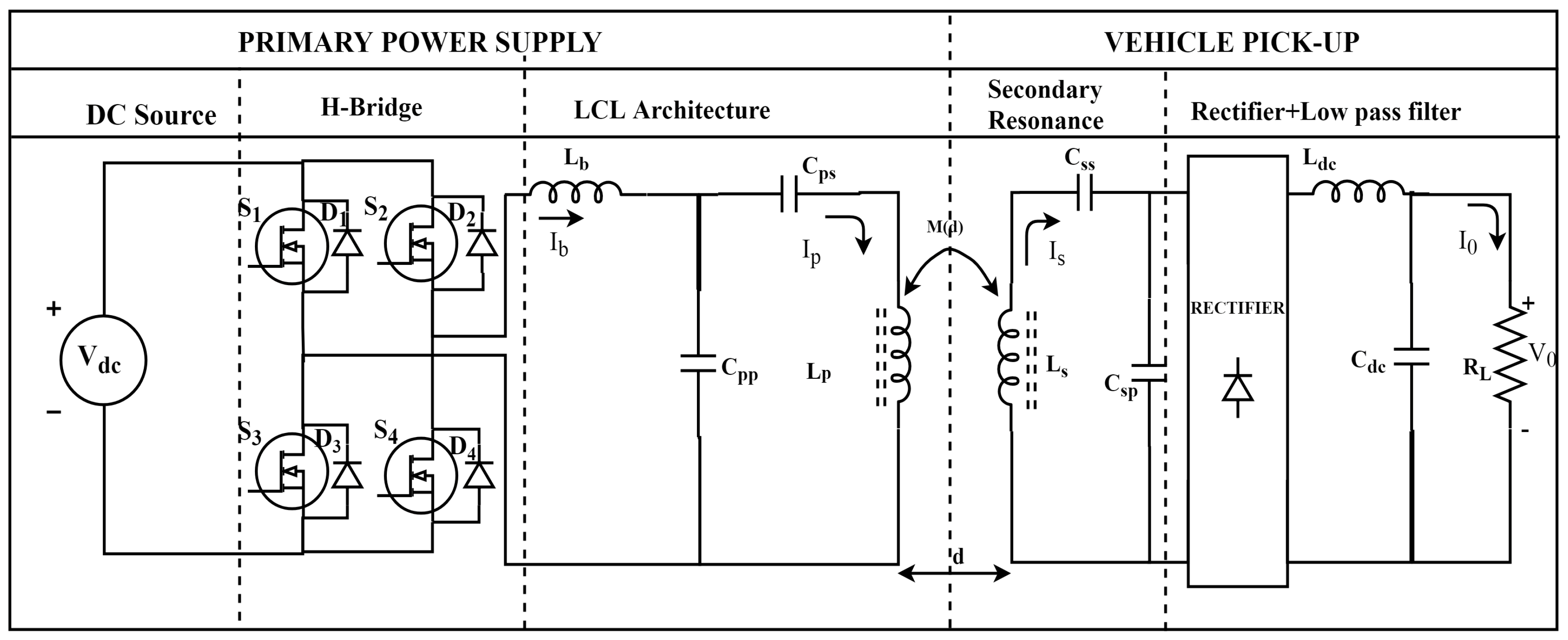
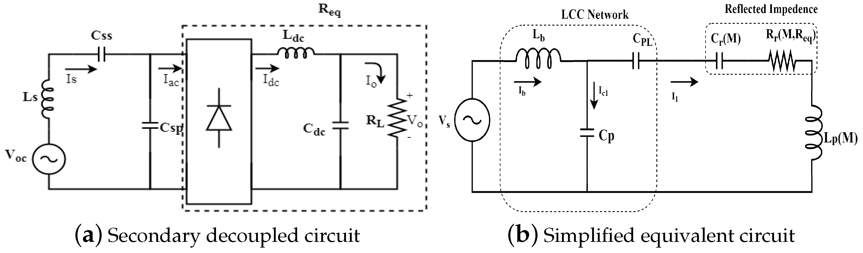
2. LCL IPT Architecture

An LCL-based IPT system is contemplated throughout this study. A magnetically-coupled electrically isolated circuit is simplified, for further analysis.
The conventional LCL IPT system is shown in Figure 1. The simplified equivalent circuit and the secondary decoupled circuit of the aforementioned IPT topology are shown in Figure 2. Secondary side circuit elements have been referred to primary to simplify the coupled circuit. The equivalent resistance R e q , seen instead of the rectifier connected to the load through a low pass filter, is written as
R e q = π 2 R L 8 ,
where R L is the load resistance [6]. Similarly, the secondary resonance frequency ω s is written in terms of the secondary circuit parameters as
ω s = 1 L s e q C s p ,
where the L s e q is the secondary equivalent inductance and C s p is the secondary parallel capacitance. L s e q is written in terms of the secondary series capacitance C s s , as well as the secondary inductance L s , as
L s e q = L s 1 ω 2 C s s .
From the primary equivalent circuit, the primary equivalent inductance L p e q is written as
L p e q = L p 1 ω 2 C p s 1 ω 2 C r .
The reflected impedance consist of a reflected resistor and reflected capacitor, which is referred from secondary to primary. In which, the reflected capacitance is written as
C r ( M , R e q ) = R e q 2 ( w 2 C s p L s e q 1 ) 2 + ( w L s e q ) 2 ( w 4 M 2 ) [ C s p R e q 2 ( w 2 C s p L s e q 1 ) + L s e q ] .
Similarly, the reflected resistance is written as
R r ( M , R e q ) = R e q ( w M ) 2 [ w 2 C s p L s e q ( w 2 C s p L s e q 1 ) ] R e q 2 ( w 2 C s p L s e q 1 ) 2 + ( w L s e q ) 2 .
The primary resonance frequency is obtained by
ω p = 1 L p e q C p p .
It was observed, from the aforementioned expression, that the primary resonance frequency ω p is a function of primary equivalent inductance. The primary equivalent inductance is a function of reflected capacitance, according to (4). Further, the reflected capacitance is a function of mutual inductance. This, in turn, correlates the mutual inductance and resonance frequency.

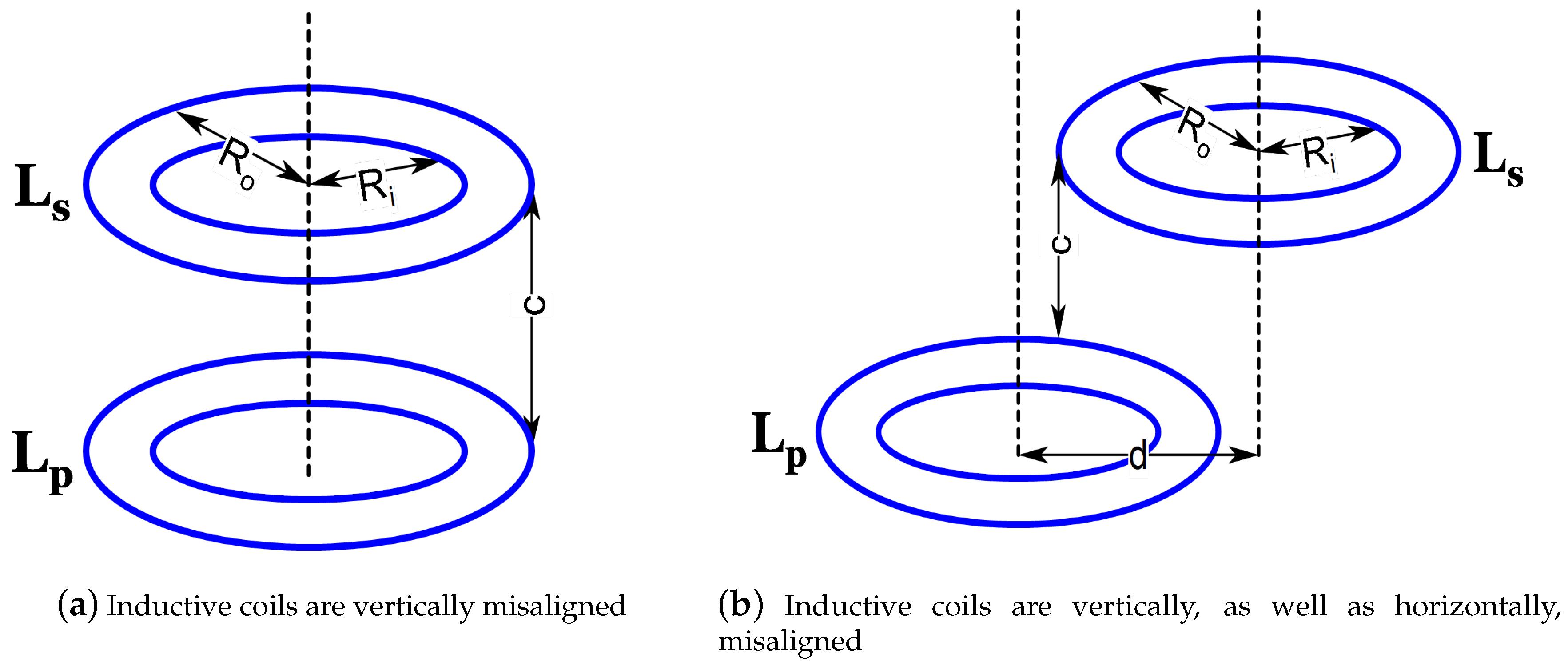
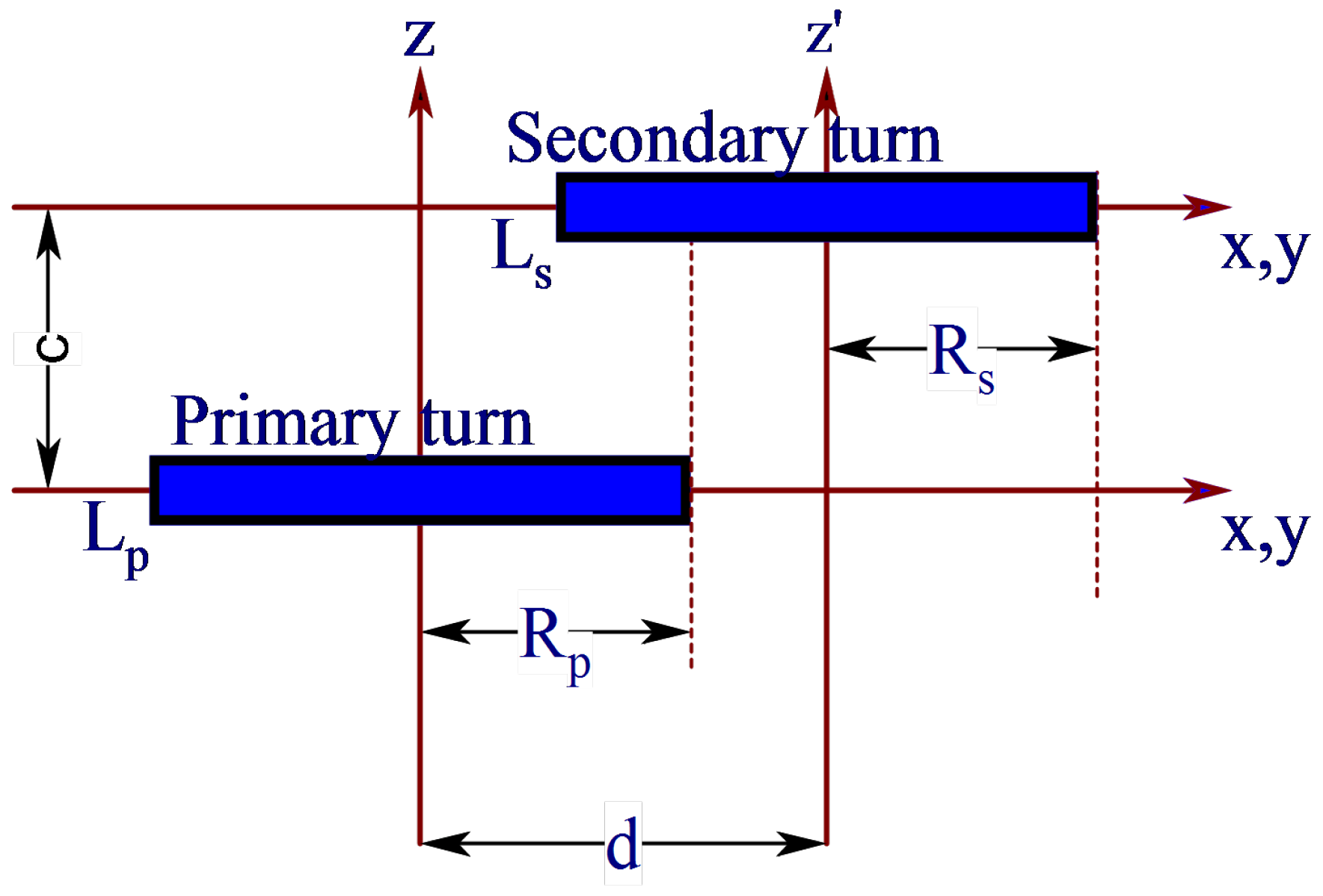
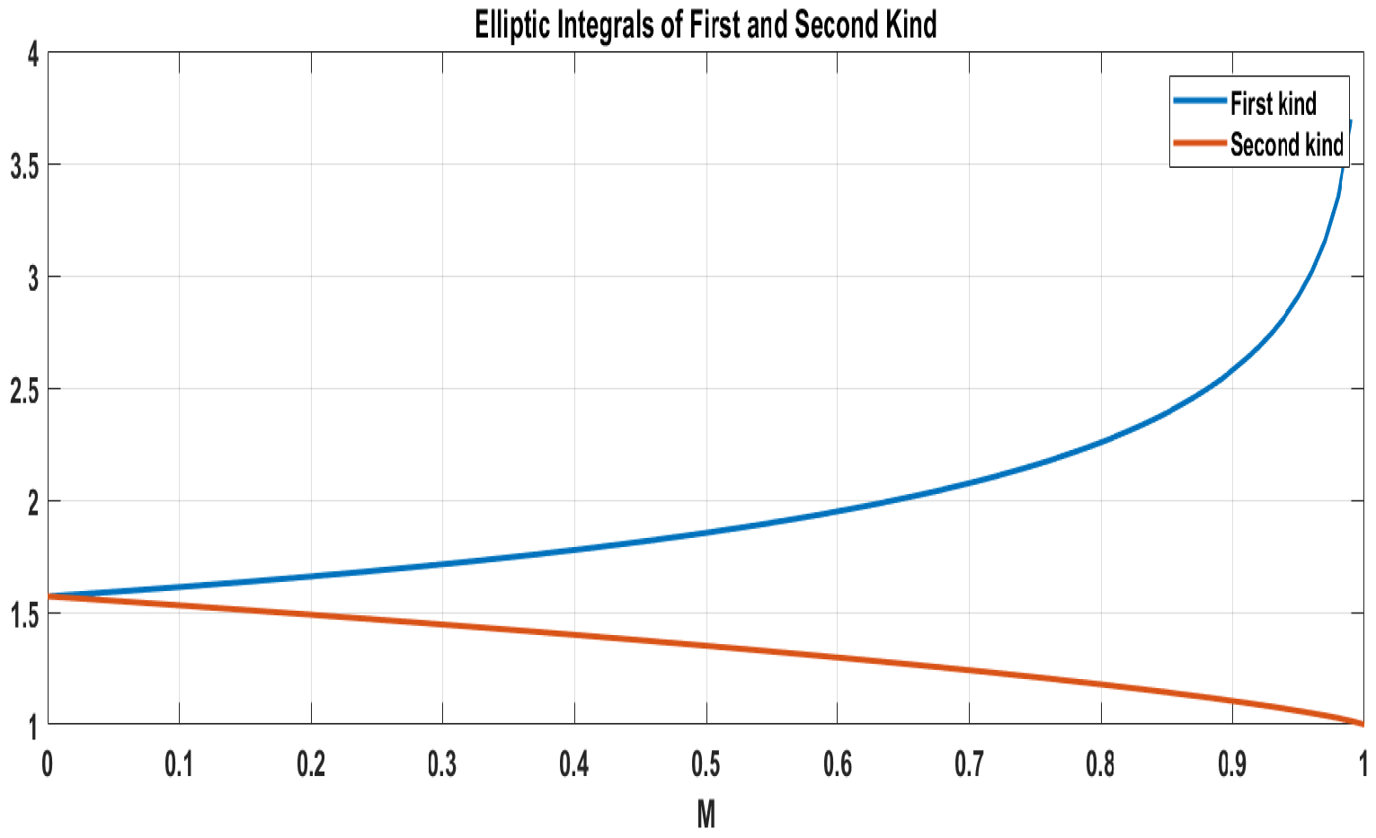
3. Computation of Self and Mutual Inductance

Self and mutual inductance of the coils are calculated analytically. The vertical and horizontal misalignment of pickup coil about the center axis is shown in Figure 3. Wheeler’s formula of approximation is quite useful in this case, in which the self inductance is represented in terms of the physical dimensions of the inductive coil
L ( μ H ) = r 2 N 2 8 r + 11 w ,
where r is the radius to the center of the winding (in inches). The radius r is determined by R o + R i 2 . W is the width of the winding in inches. The width W is determined by R o R i from the Figure 3. N is the number of turns and L is the self-inductance of the coil in μ H. Neumann’s formula is used to calculate the mutual inductance between the coils analytically [10,12].
The mutual inductance between the ith conductor in the primary coil and the jth conductor in the secondary coil is written as
M i j = μ o π R p R s 0 π ( 1 d R s cos ϕ ) Ψ ( k ) V 3 d ϕ ,
where V is the function of horizontal distance between the center of the axis d and Ψ is the function of elliptical integrals of first (K(k)) and second E(k) kind. R p is the radius of the single primary circular conductor and the R s is the radius of the single secondary circular conductor. In case there is no horizontal misalignment, then the value of V is 1. Figure 4 represents the individual turns of the inductive coil, displaced vertically as well as horizontally
V = 1 + d 2 R s 2 2 d R s cos ϕ ,
Ψ ( k ) = ( 2 k k ) K ( k ) 2 k E ( k ) .
In (11), the elliptical integral of first kind is written as
K ( m ) = o π 1 1 m sin 2 θ d θ ,
similarly, the elliptical integral of second kind is written as
E ( m ) = 0 π 1 m sin 2 θ d θ .
The elliptical integrals of first and second kind are plotted against m, as per (12) and (13).
Figure 5 represents the elliptical integrals of first and second kind. When m approaches 1, the curve departs away in two directions with a considerable difference. This indicates that the difference between the elliptical integrals of first and second kind increase as m approaches 1. Meanwhile, the elliptical integrals can be represented as Taylor series expansions, and the error in approximation will be high when the coil vertical misalignment is very small to the outer diameter. Hence, the analytical expressions will be accurate when the coils are separated by a considerable distance. Similarly,
α = R s R p , and
β = c R p .
k is represented in terms of α and β by
k 2 = 4 α V ( 1 + α V ) + β 2 .
In case there is no horizontal misalignment, k is reduced to
k 2 = 4 R p R s ( R p + R s ) 2 + c 2 .
The expression for vertical misalignment and mutual inductance is reduced further by
M i j = 2 μ o R p R s k { ( 1 k 2 2 ) K ( m ) E ( m ) } ,
where m = k 2 and the entire mutual inductance will be the sum of all the ith and jth combinations of the coil.

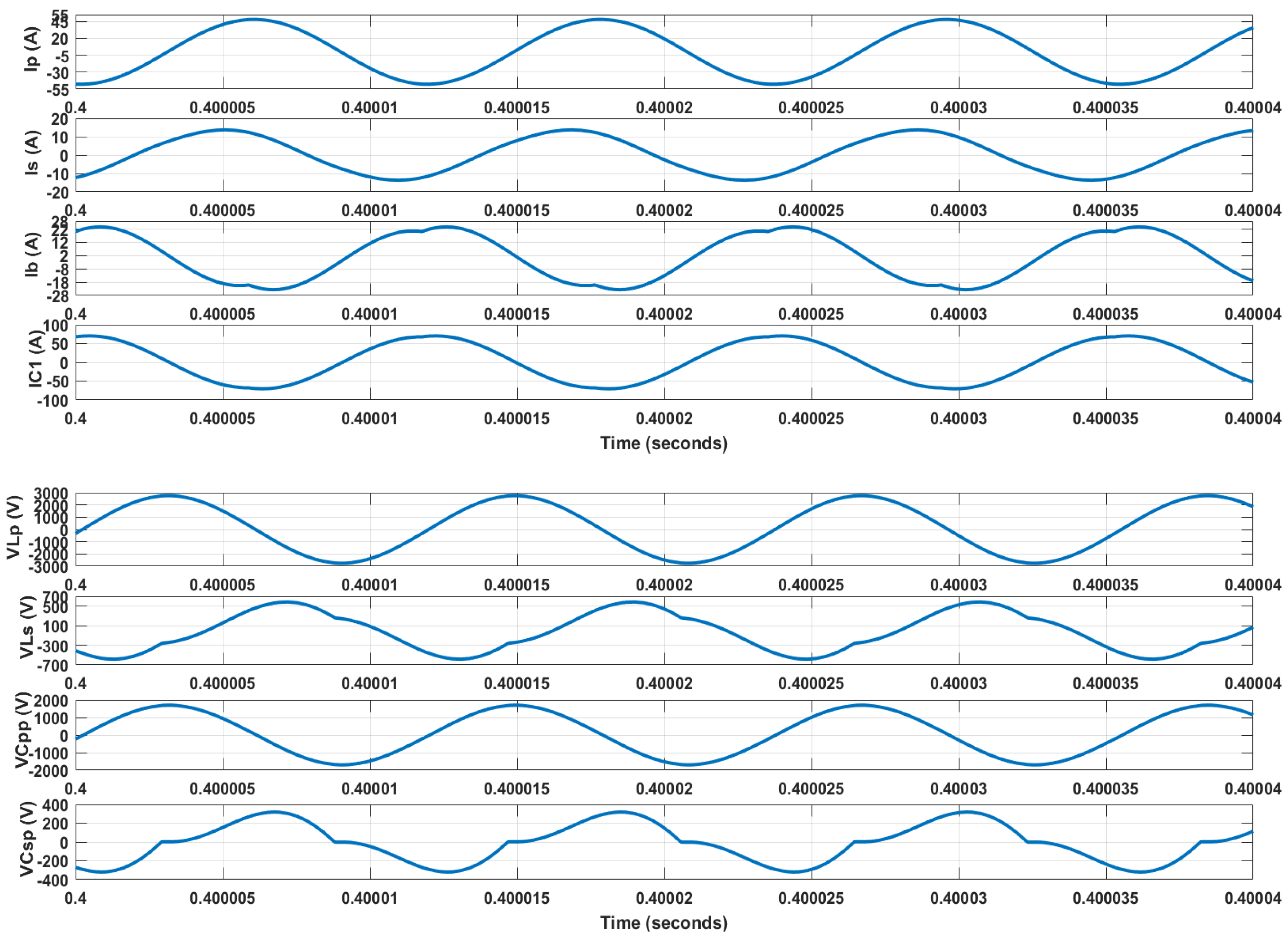
4. Numerical Simulation Results

The circular pancake inductive coils, used for the IPT system, are developed in the ANSYS Maxwell simulation platform. The mutual inductances, corresponding to different misalignments, are computed by the simulation model shown in Figure 6.
A dynamic mechanical structure was developed, in order to test the misalignment effect of inductive coil. Vertical and horizontal misalignments were tested with the developed prototype.
The coil was typically displaced vertically by 20 cm. Similarly, the pickup coil was horizontally displaced by 16 cm. The range was chosen according to the average clearance of the conventional vehicles in the market. The elliptical integrals in the analytical expressions can be expanded in Taylor series expansions; the higher-order differential terms were omitted for fast convergence, and the effect was neglected in the expression. The simulation was run based on the finite element method in the ANSYS Maxwell platform. Hence, the simulated results were more accurate than the analytically computed one. In general, the mutual inductance increased while the pickup coil approached the primary coil. Similarly, mutual inductance falls rapidly when the horizontal misalignment increases. This study eventually brings the variation in mutual inductance corresponding to the misalignment in the IPT system. It is observed that the Neumann’s formula-based analytical expression corroborates the simulated results obtained from the ANSYS Maxwell simulation platform. The coupling coefficients, corresponding to the various misalignments, are shown in Figure 7. Coupling coefficient is shown against horizontal misalignment Figure 7a, and against vertical misalignment in Figure 7b. A dynamic IPT structure was designed and developed, in order to accurately measure the misalignment and test the dynamic behavior of the system shown in Figure 8.

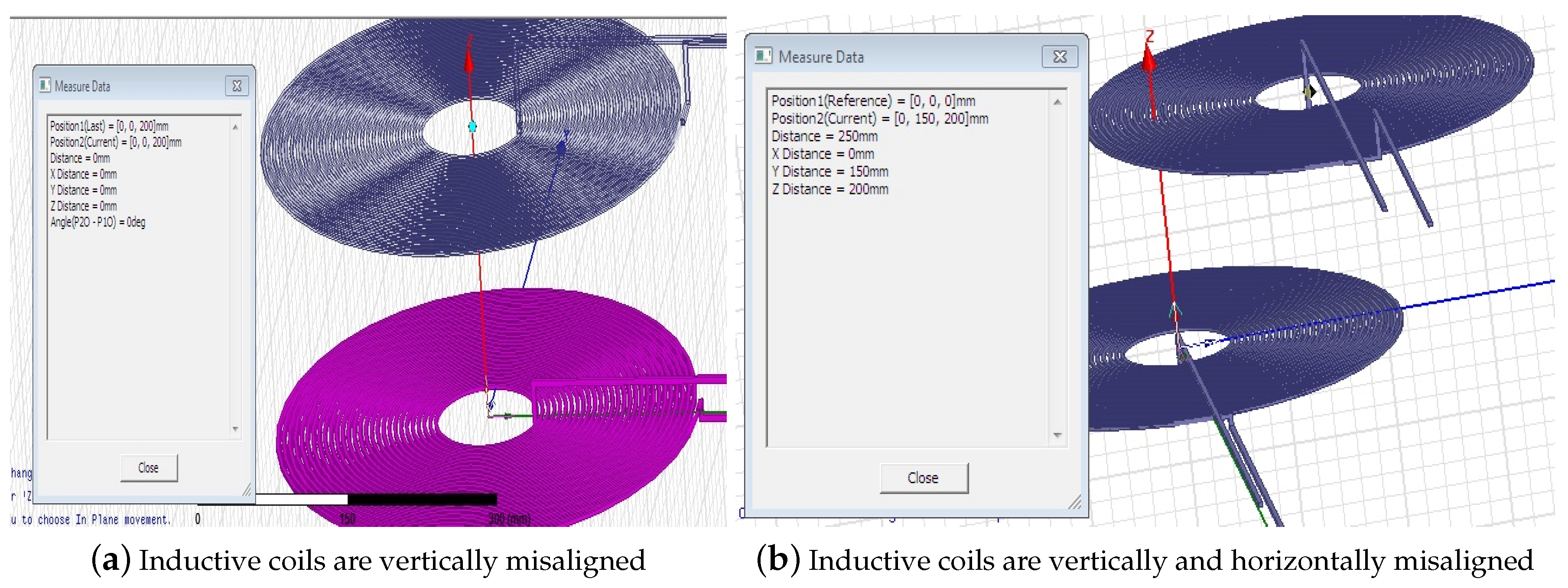
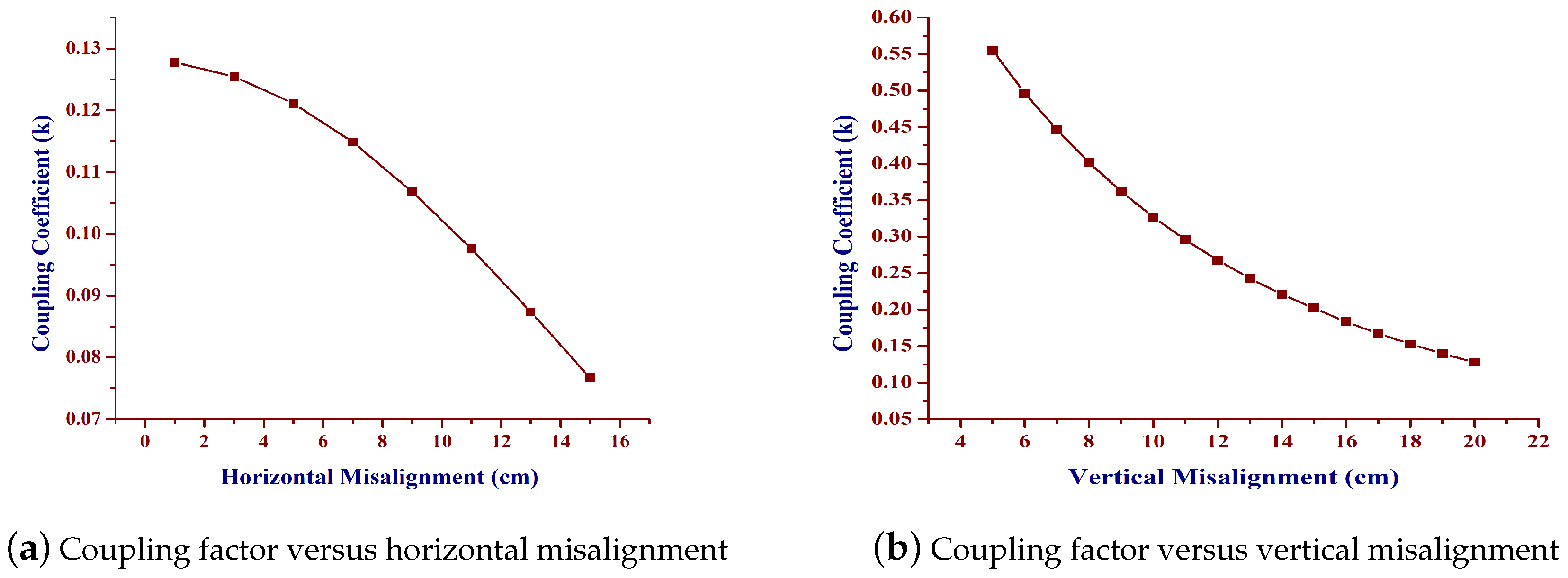
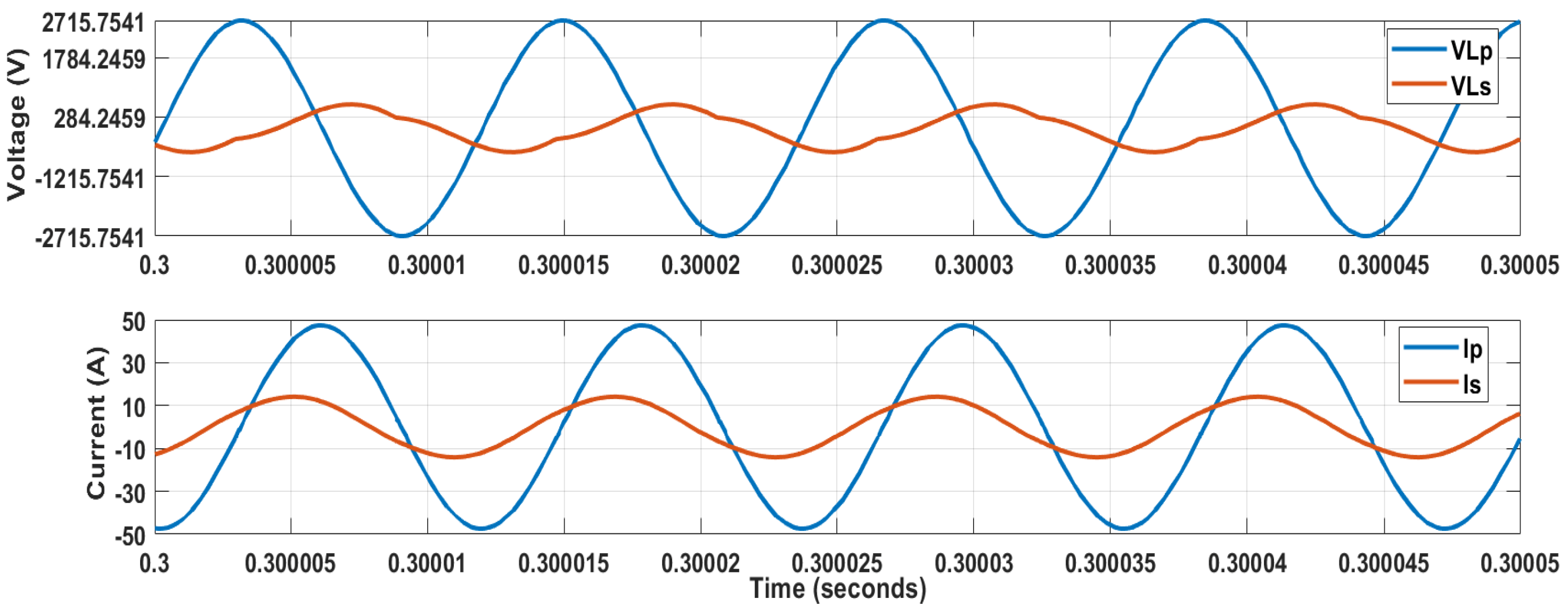
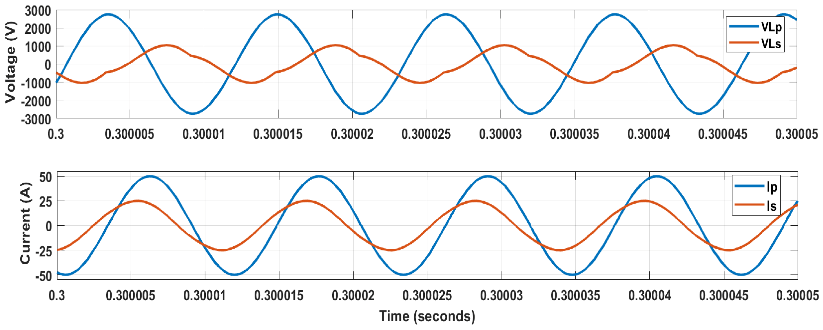
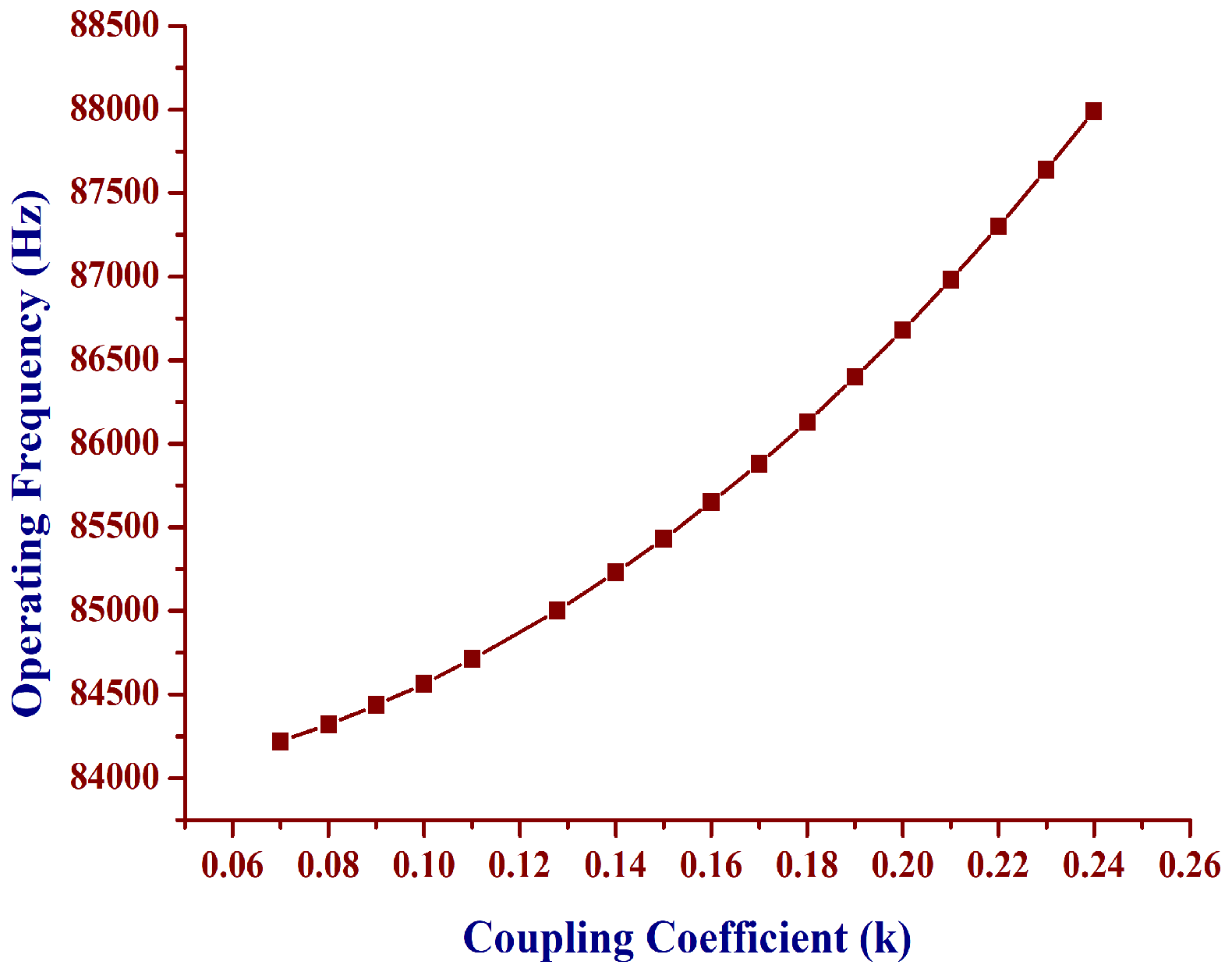
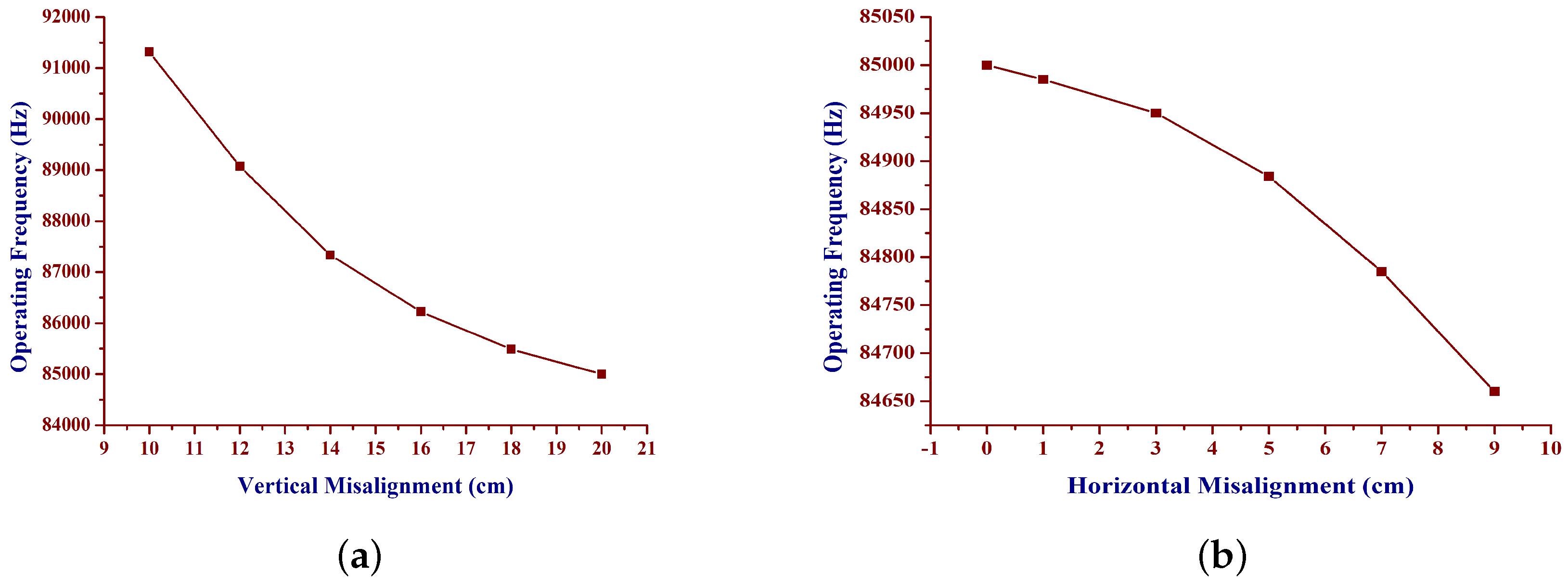
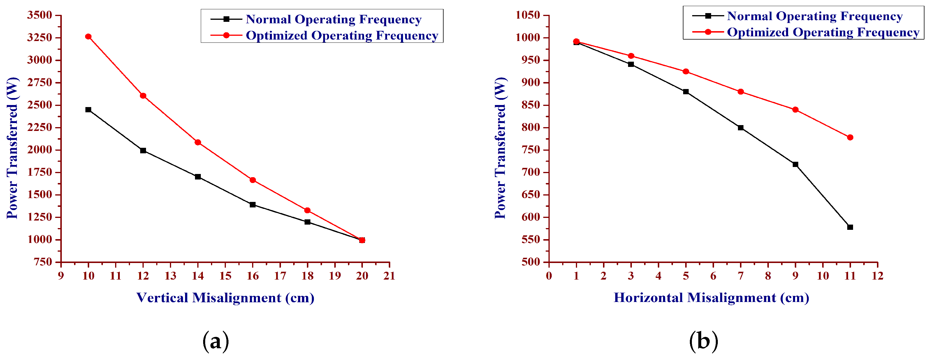
5. Simulation Studies

The entire IPT system was simulated in the MATLAB simulink platform, in order to evaluate the performance of the system. The steady state current and voltage waveform of the system is shown in Figure 9. The internal resistance of the energy storage elements, on resistance of the semiconductor switches, are considered for simulation. A resistive load, equivalent to the value of the steady-state equivalent resistance of the battery, is considered as the load. The system is operated at an 85 kHz operating frequency. The secondary side of the IPT part is designed with the same resonance frequency.
A smooth sinusoidal current is drawn by the primary inductive track during operation. The harmonic content in the waveforms was much less. It was interpreted that the increase and decrease in current values were due to the variation in resonance conditions and the reflected load changes. The values of reflected capacitance and reflected resistance from secondary side changes, according to the mutual inductance variation. Further, the simulation provides information regarding the changes in the instantaneous current and voltage values.

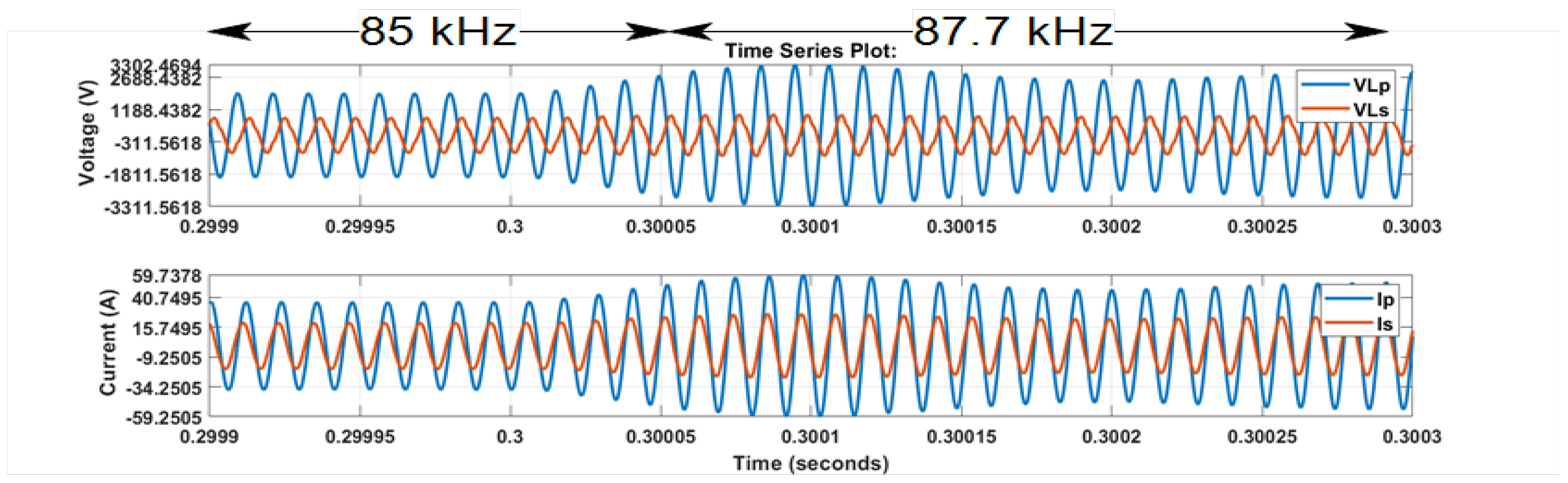
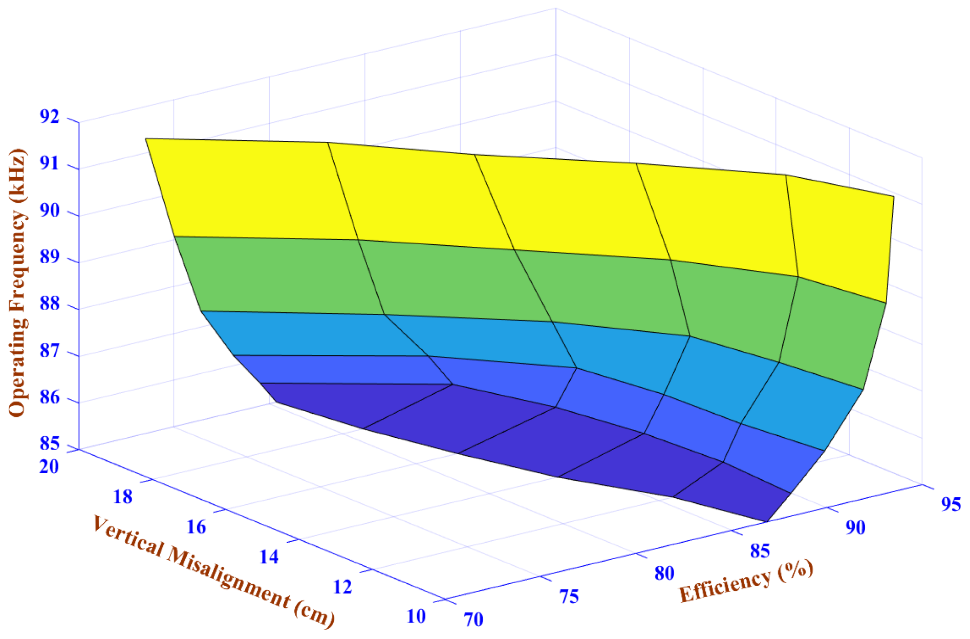
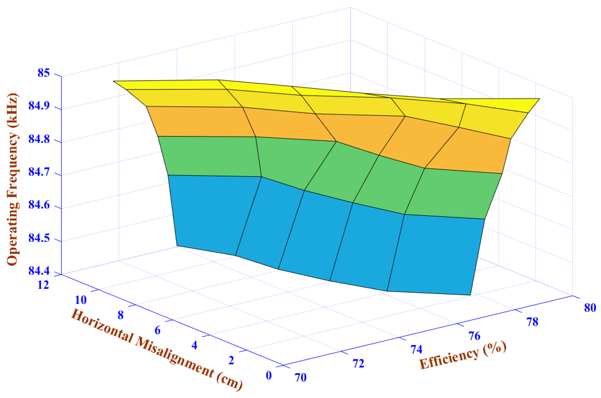
6. Selection of Operating Frequency

The operating frequency corresponding to maximum power transfer is identified based on the conditions of resonance, as per the design equation of an LCL based IPT system,
ω L b = 1 ω C p p = ω L p e q .
The bridge inductor L b limits the current and C p p is the primary parallel capacitance.
In accordance with the misalignment of the pickup coil, the mutual inductance varies. The resonance frequency depends upon the primary capacitance and primary equivalent inductance ( L p e q ) which, in turn, depend upon the mutual inductance. An IPT system with 14 μ H mutual inductance is excited with an 85 kHz operating frequency and 25 μ H mutual inductance with an 87.7 kHz operating frequency. The corresponding voltage and current through the primary and secondary inductive tracks was observed in the simulation and shown in Figure 10 and Figure 11.
An IPT system with 25 μ H mutual inductance is tuned from 85 kHz to 87.7 kHz, based on the obtained frequency plot and shown in Figure 12. An increase in the magnitude of current and voltage at 87.7 kHz, on the receiver side, was observed. Hence, the tuning had done its purpose completely. The operating frequency corresponding to the coupling coefficient is shown in Figure 13.
The Figure 14 shows the operating frequency corresponding to vertical and horizontal misalignment. The aforementioned data reveal the possibility of finding the resonance frequency corresponding to the physical misalignment, according to (19). In the case where the resonance frequency matches with the operating frequency, the circuit offers less impedance for the high frequency supply. This relationship was concluded analytically, and was validated through the simulation studies. Circuit parameters and values of the IPT system are mentioned in Table 1. Further, an experimental prototype was built to validate the notion in both theoretical and simulated aspects.
The power transferred to the reflected load will be
P = R e { I p 2 Z r } ,
where Z r is the reflected impedance from the secondary side. Further,
P = R e q ( ω M I p ) 2 [ ω 2 C s p L s e q ( ω 2 C s p L s e q 1 ) ] R e q 2 ( ω 2 C s p L s e q 1 ) 2 + ( ω L s e q ) 2 .
Now, the mutual inductance is the function of vertical and horizontal misalignment by Neumann’s formula, and the power transferred to the reflected load is the function of mutual inductance. Hence, the power transferred from primary to the secondary, according to the misalignment, was plotted and the improvement in power transfer level is observed in Figure 15a,b.

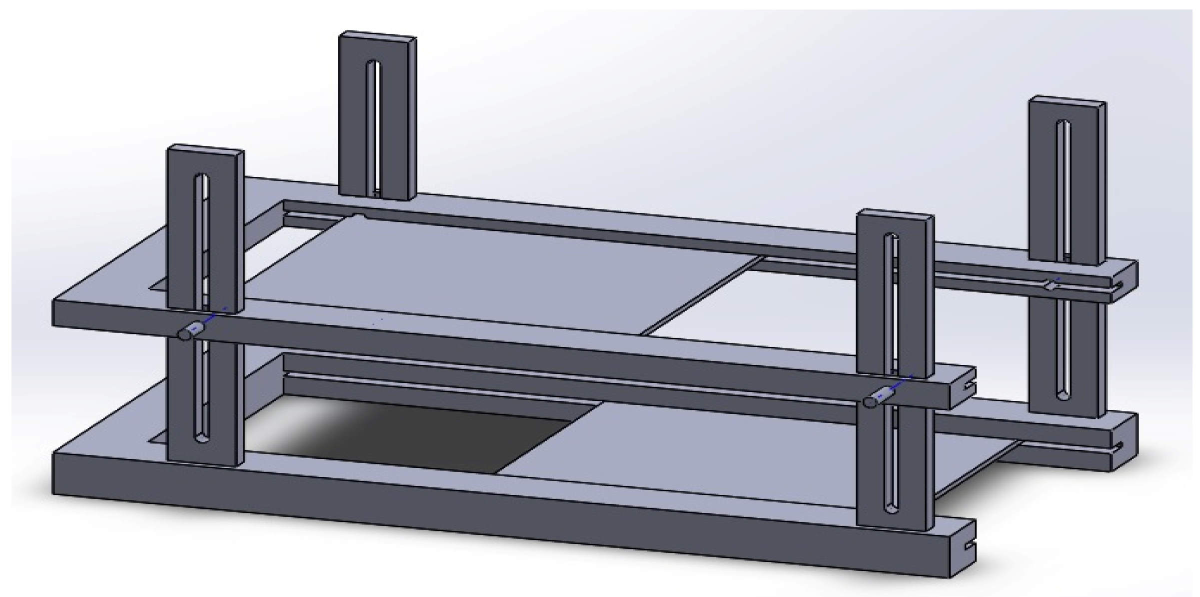
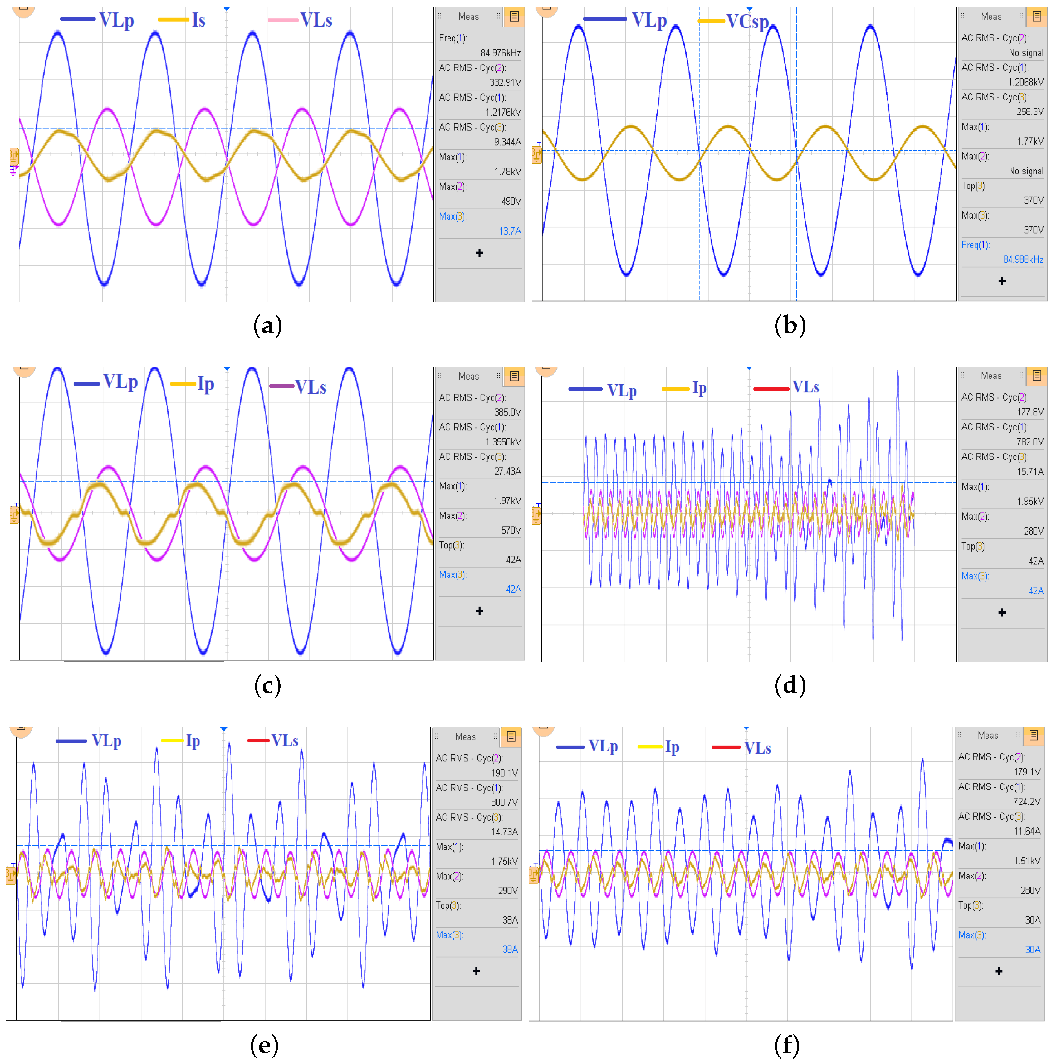
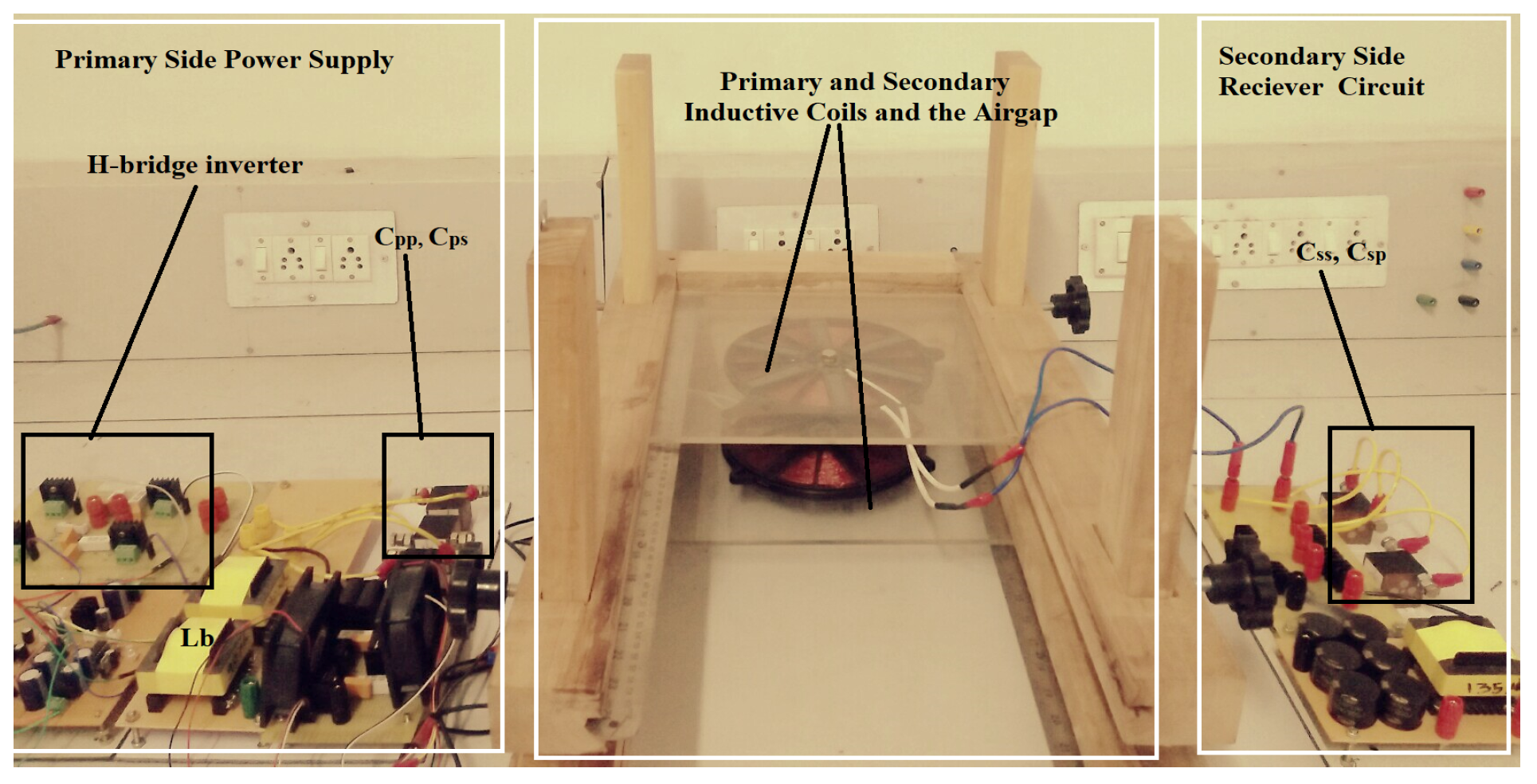
7. Experimental Studies

An experimental prototype was built to evaluate the real-time performance of the system.
High frequency switching MOSFETs (SPW47N60C3) were used for inverting purposes, whereas high frequency diodes (MUR1560G) were used as un-controlled rectifier switches. A co-axial pancake circular coil, made of copper, was mounted on a ferrite spoke, in order to enhance the flux linkage on the pickup coil. The simulation studies were carried out with an ideal copper conductor. However, it was observed that the experimental results with ferrite spokes were closer to the simulated data. High-frequency poly-polypropylene power film capacitors were used as resonance capacitors for the system. The dynamic structure of the coils made a wide range of misalignment possible in the vertical and horizontal directions. The resistive bank, equivalent to the steady state equivalent resistance of the battery, was considered as load.
The steady state current and voltage waveforms are shown in Figure 16a–c. The presence of the AC transients are shown in Figure 16d–f. The current waveform was sinusoidal, which has less harmonic content. The current and voltage waveforms were distorted, due to sudden changes in the position of the pickup coil (Figure 16d). However, the slight misalignment did not make much difference in the current and voltage waveforms (Figure 16f). The developed experimental prototype is shown in Figure 17. The experiments were conducted for static, as well as dynamic, movements of the pickup coil. The primary and secondary currents were distorted, due to the perturbations in the position of the pickup coil. This shows that the velocity of the coil movement and the position of coil decided the amount of distortion present in the voltage and current waveform.
Power transfer efficiency of the IPT system was recorded from the experimental prototype under various misalignments. A 3-D surface plot was plotted for power transfer efficiency against misalignment and operating frequency. The vertical misalignment and power transfer efficiency corresponding to various frequencies is shown in Figure 18. Similarly, the horizontal misalignment and power transfer efficiency corresponding to various frequencies is shown in Figure 19. The obtained results were tabulated and shown in Table 2 and Table 3. For vertical misalignments from 10 cm to 20 cm, the power transfer efficiency varied from 86.85% to 80.36% at an 85 kHz operating frequency. However, under the optimal operating frequency, the efficiency was improved to 93.5% for a 10 cm misalignment at 91.315 kHz. In the case of horizontal misalignment, the coils were horizontally misaligned from 1 cm to 11 cm, and the coil was vertically misaligned by 20 cm. Under vertical misalignment, the operating frequency was selected based on maximum power transfer, and the corresponding power transfer efficiency observed. The efficiency varied from 73.36% to 79.5%, under the optimal operating frequency. Thus, the proper selection of operating frequency, corresponding to the dynamic changes of the pickup coil, improved the power transfer efficiency.

8. Conclusions

The operating frequency, corresponding to the resonance condition, with reference to the mutual inductance over the LCL IPT architecture is analytically studied. Similarly, the mutual inductance, corresponding to the misalignment, is analytically studied based on the Neumann’s approximation formula. It was inferred that both results give a relation between the operating frequency and misalignment. Further, the operating frequency corresponding to the misalignment is identified in the proposed work, and the results are validated by simulation and experimental studies.

Author Contributions

Conceptualization, S.V. and F.D.J.L.; Formal analysis, S.V.; Funding acquisition, F.D.J.L.; Methodology, S.V. and F.D.J.L.; Project administration, F.D.J.L.; Software, S.V.; Supervision, F.D.J.L.; Validation, S.V. and F.D.J.L.; Writing—original draft, S.V.; Writing—review and editing, S.V.

Funding

This research was funded by SERB, Department of Science and Technology Govt. of India, grant number YSS/2015/001277.

Acknowledgments

We thank the support extended by the Vellore Institute of Technology Research laboratory for developing the prototype and funding provided by the SERB, DST for carry out the research.

Conflicts of Interest

The authors declare no conflict of interest. The funders had no role in the design of the study; in the collection, analyses, or interpretation of data; in the writing of the manuscript, or in the decision to publish the results.

Abbreviations

The following abbreviations are used in this manuscript:
IPTInductive power transfer
EMFElectro motive force

References

  1. Boys, J.T.; Covic, G.A. The Inductive Power Transfer Story at the University of Auckland. IEEE Circuit Syst. Mag. 2015, 15, 6–27. [Google Scholar] [CrossRef]
  2. Dai, J.; Ludois, D.C. A Survey of Wireless Power Transfer and a Critical Comparison of Inductive and Capacitive Coupling for Small Gap Applications. IEEE Trans. Power Electron. 2015, 30, 6017–6029. [Google Scholar] [CrossRef]
  3. Wang, T.; Liu, X.; Jin, N.; Tang, H.; Yang, X.; Ali, M. Wireless Power Transfer for Battery Powering System. Electronics 2018, 7, 281. [Google Scholar] [CrossRef]
  4. Choi, S.Y.; Gu, B.W.; Jeong, S.Y.; Rim, C.T. Advances in wireless power transfer systems for roadway-powered electric vehicles. IEEE J. Emerg. Sel. Top. Power Electron. 2015, 2, 18–36. [Google Scholar] [CrossRef]
  5. Miller, J.M.; Jones, P.T.; Li, J.; Onar, O.C. ORNL experience and challenges facing dynamic wireless Power charging of EV’s. IEEE Trans. Ind. Inform. 2012, 8, 585–595. [Google Scholar] [CrossRef]
  6. Esteban, B.; Ahmed, M.S.; Kar, N.C. A comparative study of power supply architectures in wireless EV charging system. IEEE Trans. Power Electron. 2015, 30, 6408–6422. [Google Scholar] [CrossRef]
  7. Wu, H.H.; Gilchrist, A.; Sealy, K.D.; Bronson, D. A high efficiency 5 kW inductive charger for EVs using dual side control. IEEE Trans. Ind. Inform. 2012, 8, 585–595. [Google Scholar] [CrossRef]
  8. Wang, Ch.; Stielau, O.H.; Covic, G.A. Design Considerations for a Contactless Electric Vehicle Battery Charger. IEEE Trans. Ind. Electron. 2005, 52, 1308–1314. [Google Scholar] [CrossRef]
  9. Wang, Ch.; Covic, G.A.; Stielau, O.H. Investigating an LCL load resonant inverter for inductive power transfer applications. IEEE Trans. Power Electon. 2004, 19, 995–1002. [Google Scholar] [CrossRef]
  10. Imura, T.; Hori, Y. Maximizing air gap and efficiency of magnetic resonant coupling for wireless power transfer using equivalent circuit and Neumann formula. IEEE Trans. Ind. Electron. 2011, 58, 4746–4752. [Google Scholar] [CrossRef]
  11. Stergiou, C.A.; Zaspalis, V. Impact of ferrite shield properties on the low-power inductive power transfer. IEEE Trans. Mag. 2016, 52, 8401601–8401609. [Google Scholar] [CrossRef]
  12. Sooraj, V. A study of magnetic coupling and selection of operating frequency for static and dynamic EV charging system. In Proceedings of the 2016 IEEE International Conference on Circuit, Power and Computing Technologies (ICCPCT), Nagercoil, India, 18–19 March 2016; pp. 1–4. [Google Scholar]
  13. Vazquez, J.; Roncero-Sanchez, P.; Parreno, A. Simulation Model of a 2-kW IPT Charger with Phase-Shift Control: Validation through the Tuning of the Coupling Factor. Electronics 2018, 7, 255. [Google Scholar] [CrossRef]
  14. Akyel, S.; Babic, I.; Mahmoudi, M.-M. Mutual inductance calculation for non-coaxial circular air coils with parallel axes. Prog. Electromagn. Res. 2009, 91, 287–301. [Google Scholar] [CrossRef]
  15. Varikkottil, S.; Daya, J.L.F. High-gain LCL architecture based IPT system for wireless charging of EV. IET Power Electron. 2019, 12, 195–203. [Google Scholar] [CrossRef]
  16. Houran, M.A.; Yang, X.; Chen, W. Magnetically Coupled Resonance WPT: Review of Compensation Topologies, Resonator Structures with Misalignment, and EMI Diagnostics. Electronics 2018, 7, 296. [Google Scholar] [CrossRef]
  17. Liu, X.; Jin, N.; Yang, X.; Wang, T.; Hashmi, K.; Tang, H. A Novel Synchronization Technique for Wireless Power Transfer Systems. Electronics 2018, 7, 319. [Google Scholar] [CrossRef]
  18. Feng, H.; Cai, T.; Duan, S.; Zhao, J.; Zhnag, X.; Chen, C. An LCC compensated resonance converter optimized for robust reaction to large coupling variation in dynamic wireless power transfer. IEEE Trans. Ind. Electron 2016, 63, 6591–6601. [Google Scholar] [CrossRef]
  19. Luo, B.; Long, T.; Mai, R.; Dai, R.; He, Z.; Li, W. Analysis and design of hybrid inductive and capacitive wireless power transfer for high-power applications. IET. Power Electron 2018, 11, 2263–2270. [Google Scholar] [CrossRef]
  20. Lu, M.; Ngo, K.D.T. Systematic Design of Coils in Series–Series Inductive Power Transfer for Power Transferability and Efficiency. IEEE Trans. Power Electron 2018, 33, 3333–3345. [Google Scholar] [CrossRef]
  21. Moghaddami, M.; Sarwat, A.I. Single-Phase Soft-Switched AC–AC Matrix Converter With Power Controller for Bidirectional Inductive Power Transfer Systems. IEEE Trans. Ind. Appl. 2018, 54, 3760–3770. [Google Scholar] [CrossRef]
  22. Hou, J.; Chen, Q.; Zhang, Z.; Wong, Si.; Tse, C.K. Analysis of Output Current Characteristics for Higher Order Primary Compensation in Inductive Power Transfer Systems. IEEE Trans. Power Electron. 2018, 33, 6807–6821. [Google Scholar] [CrossRef]
  23. Kamineni, A.; Covic, G.A.; Boys, J.T. Analysis of Coplanar Intermediate Coil Structures in Inductive Power Transfer Systems. IEEE Trans. Power Electron. 2015, 30, 6141–6154. [Google Scholar] [CrossRef]
  24. Babic, S.I.; Akyel, C. New analytic-numerical solutions for the mutual inductance of two coaxial circular coils with rectangular cross section in air. IEEE Trans. Magn. 2006, 42, 1661–1669. [Google Scholar] [CrossRef]
  25. Khan, S.R.; Pavuluri, S.K.; Desmulliez, M.P.Y. Accurate Modeling of Coil Inductance for Near-Field Wireless Power Transfer. IEEE Trans. Microw. Theory Tech. 2018, 66, 4158–4169. [Google Scholar] [CrossRef]
  26. Gao, Y.; Ginart, A.; Duan, C.; Farley, K.B.; Tse, Z.T.H. Simple approach to calculate unity-gain frequency of series–series compensated inductive power transfer. IET Electron. Lett. 2016, 52, 145–146. [Google Scholar] [CrossRef]
Figure 1. LCL based IPT system.
Electronics 08 00342 g001
Figure 2. Simplified circuit.
Electronics 08 00342 g002
Figure 3. Misalignment of inductive coil.
Electronics 08 00342 g003
Figure 4. Circular coils with vertical and horizontal misalignment.
Electronics 08 00342 g004
Figure 5. Complete elliptical integrals of the first and second kinds.
Electronics 08 00342 g005
Figure 6. Misalignment of inductive coils under numerical simulation.
Electronics 08 00342 g006
Figure 7. Coupling factors for various misalignments.
Electronics 08 00342 g007
Figure 8. Dynamic structure of the IPT coil plates.
Electronics 08 00342 g008
Figure 9. Steady-state voltage and current waveform of various circuit elements.
Electronics 08 00342 g009
Figure 10. Voltage and current waveform of the inductive track at M = 14 μ H and f = 85 kHz.
Electronics 08 00342 g010
Figure 11. Voltage and current waveform of the inductive track at M = 25 μ H and f = 87.7 kHz.
Electronics 08 00342 g011
Figure 12. Voltage and current waveform of inductive track at M = 25 μ H while tuning.
Electronics 08 00342 g012
Figure 13. Operating frequency corresponding to coupling coefficient.
Electronics 08 00342 g013
Figure 14. Operating frequency corresponding to misalignment. (a) Operating frequency corresponding to the vertical misalignment. (b) Operating frequency corresponding to the horizontal misalignment.
Electronics 08 00342 g014
Figure 15. Power transfer level corresponding to the misalignment. (a) Power transferred corresponding to the vertical misalignment. (b) Power transferred corresponding to the horizontal misalignment.
Electronics 08 00342 g015
Figure 16. Experimental waveforms. (a) Voltage V L p , current I s , and voltage V L s . (b) Voltage V L p and V C s p . (c) Steady state voltage and current waveform. (d) AC transients, due to horizontal misalignment. (e) AC transients, due to horizontal and vertical misalignment. (f) AC transients, due to minor perturbations ofthe coil.
Electronics 08 00342 g016
Figure 17. Experimental prototype of LCL architecture.
Electronics 08 00342 g017
Figure 18. Power transfer efficiency against to the vertical misalignment and operating frequency.
Electronics 08 00342 g018
Figure 19. Power transfer efficiency against to the horizontal misalignment and operating frequency.
Electronics 08 00342 g019
Table 1. Circuit parameters and values.
ParameterValue
Power, P1 kW
Operating frequency, f85 kHz
Primary Inductance, L p 110 μ H
Secondary Inductance, L s 110 μ H
Minimum coupling coefficient, k m i n 0.08
ControllerTexas Delfino (TMS320F28377S)
MOSFETSPW47N60C3
DiodeMUR1560G
Capacitor, C s p 50 nF
Capacitor, C s s 85 nF
Capacitor, C p s 53.2 nF
Capacitor, C s s 85 nF
Capacitor, C d c 2200  μ F
Inductor, L d c 135 μ H
Table 2. Efficiency corresponding to the vertical misalignment under various operating frequencies.
Vertical Efficiency %
Misalignment (cm)f = 91,315 Hzf = 89,070 Hzf = 87,337 Hzf = 86,223 Hzf = 85,990 Hzf = 85,000 Hz
2073.575.0176.478.179.580.36
1879.280.882.1784.4785.7581.05
1683.0585.1487.1288.487.382.18
1487.6789.4890.589.1388.183.57
1291.6892.3391.3289.3288.4085.76
1093.593.191.989.8888.1186.85
Table 3. Efficiency corresponding to the horizontal misalignment under various operating frequencies.
Horizontal Efficiency %
Misalignment (cm)f = 84,985 Hzf = 84,950 Hzf = 84,884 Hzf = 84,785 Hzf = 84,660 Hzf = 84,440 Hz
179.579.178.578.277.677.1
377.378.2377.9876.876.175.5
575.9376.9177.4176.575.674.8
774.7575.175.5876.3175.274.3
973.573.874.3574.87574.1
1171.1571.672.372.773.0573.36

