Article

Efficient FPGA-Based Architecture of the Overlap-Add Method for Short-Time Fourier Analysis/Synthesis

Department of Engineering, Université du Québec à Rimouski, 300, allée des Ursulines, Rimouski, QC G5L 3A1, Canada
Electronics 2019, 8(12), 1533; https://doi.org/10.3390/electronics8121533
Submission received: 15 October 2019 / Revised: 5 December 2019 / Accepted: 9 December 2019 / Published: 12 December 2019
(This article belongs to the Section Circuit and Signal Processing)

Abstract

:
This paper proposes a simple and efficient FPGA-based architecture of the overlapping/windowing and overlap-add methods for real-time FFT/IFFT-based signal processing algorithms. The analyzed signal is divided into short-time overlapping frames that are windowed before applying Fourier analysis/synthesis. Then, the original signal is reconstructed from the windowed (modified) frames using the overlap-add (OLA) technique. The proposed architecture was implemented on Field Programmable Gate Array (FPGA) using a high-level programming tool in MATLAB/SIMULINK environment. Its performance was evaluated on artificial and actual signals using objective metrics.

1. Introduction

Fourier transform is a powerful mathematical tool that converts a signal from the time domain to the frequency domain (spectrum) and vice versa. It is more appropriate to analyze stationary signals that have non-varying frequency content over time. However, most real-world signals are non-stationary in nature and necessitate the use of the time–frequency representation for analyzing their time-varying characteristics. Many techniques such as short-time Fourier transform (STFT), wavelet transform, wavelet packet transform, Wigner–Ville distribution, and S-transform have been proposed in the literature for analyzing the non-stationary signals in the time–frequency domain [1].
The short-time Fourier transform (STFT) has been widely used in many signal processing fields, such as speech enhancement [2] and recognition [3], music segmentation and classification [4], biomedical signal/image processing [5], vibration analysis, etc. [6]. The original signal is divided into successive overlapping frames and then multiplied by a smoothing window to minimize the amplitude of discontinuities at their boundaries [7]. The overlap-add (OLA) method allows a perfect reconstitution of the original signal from the windowed (modified) overlapping frames [8,9].
STFT-based techniques have been implemented on Field Programmable Gate Array (FPGA) for speech enhancement [10,11,12,13], audio indexing [14], and feature extraction [15,16,17] using Xilinx System Generator (XSG). This high-level programming tool provides a library of SIMULINK blocks allowing bit and cycle accurate modeling for digital signal processing (DSP) functions.
In this paper, an efficient FPGA-based architecture of an overlapping/windowing analysis and overlap-add synthesis techniques has been proposed for real-time signal processing algorithms based on the short-time Fourier transform. The proposed architecture is mainly based on an adequate management of dual-port RAM memories to implement the overlapping/windowing analysis and the overlap-add synthesis techniques. It has been implemented on the Nexys-4 development board using XSG programming tool.

2. Theory

2.1. Overlapping and Windowing

Let us first consider the original signal as x ( n ) , where n is the global time index varying from zero to the total number of samples. This signal is then divided in overlapping frames in order to be processed separately.
x ( m , n ) = x ( n ) w ( n m L )
where w ( n ) is a smoothing window of N samples, m is the frame index, and L is the shift-time step. The overlap rate between consecutive frames is then ( N L ) / N . A frame overlap of 50% corresponds to L = N / 2 . Overlapping and windowing steps of a typical signal are illustrated in Figure 1.
To perform this task in real-time, a circular buffer is often used. It is a fixed-size buffer designed so that its last element is connected to its first one. It is a FIFO (first-in, first-out) register, where the oldest sample is replaced (discarded) by the newest sample, thereby creating a moving window effect.

2.2. Short-Time Fourier Transform

The short-time Fourier transform (STFT) of the mth frame x ( m , n ) is defined as:
X ( m , k ) = n x ( m , n ) e j 2 π n k / N
where N also represents the number of discrete frequencies. It is usually chosen to be a power of 2 to allow the use the fast Fourier transform (FFT) algorithm.
If the windowed frames are transformed (STFT) by a single processor, they must be presented as a longer signal y ( n ) , obtained by non-overlapping concatenation of theses frames y ( n ) = [ x ( 0 , n ) x ( 1 , n ) ] . Figure 1 shows that signal frames are presented without overlapping to a single STFT processor. The Fourier transform of y ( n ) can also be seen as a non-overlapping concatenation of their corresponding STFT, i.e., Y ( k ) = [ X ( 0 , k ) X ( 1 , k ) ] .

2.3. Inverse Discrete Fourier Transform

The windowed frame x ( m , n ) can be reconstructed by transforming back X ( m , k ) using the inverse short-time Fourier transform (ISTFT):
x ( m , n ) = 1 N k = 0 N 1 X ( m , k ) e j n k 2 π / N
The back transformation to the time domain provides a non-overlapping concatenation of the windowed frames,
y ( n ) = [ x ( 0 , n ) x ( 1 , n ) ]
Figure 1 shows that signal frames are transformed back by a single ISTFT processor without overlapping.

2.4. Perfect Reconstruction

The original signal can be reconstructed by overlapping and adding (OLA) all the windowed (modified) signal frames in the time domain.
x r ( n ) = m x ( m , n )
By substituting x ( m , n ) , as defined in Equation (1), the synthesized signal can be written as
x r ( n ) = x ( n ) m w ( n m L )
For perfect reconstruction ( x r ( n ) = x ( n ) ), it is necessary to satisfy
m w ( n m L ) = 1
For 50% frame overlap ( L = N / 2 ), the left-part of Equation (7) is periodic with N / 2 period. Therefore, it is necessary to satisfy Equation (7) only for N / 2 range of n.
w ( n ) + w ( n N / 2 ) = 1 , n = N 2 , , N 1
The reconstruction condition in Equation (8) is satisfied for Hanning, Triangular, and Bartlett windows. It can also be satisfied for Hamming window by readjusting the amplitude of the reconstructed signal. Figure 2 presents the overlap-add (OLA) method using Hanning, Triangular, Bartlett, and Hamming windows of 32-sample width and 16-sample overlap (50%). The reconstruction condition is perfectly satisfied for Hanning, Triangular, and Bartlett windows ( w ( n ) + w ( n 16 ) = 1 ). For Hamming window, w ( n ) + w ( n 16 ) = 1.08 , but the original signal can be recovered by adjusting the amplitude of the reconstructed signal ( x ( n ) = x r ( n ) / 1.08 ).
The reconstruction condition in Equation (8) is also satisfied for any even value of the window width N, greater or equal to 4 (reasonable width). Figure 3 presents the overlap-add (OLA) method for the Hanning window of different widths (N samples), but a fixed shift ( L = N / 2 ) that corresponds to an overlap rate of 50%. It is also satisfied with Hamming, Triangular, and Bartlett windows for even values of the window width N and 50% overlap. However, for a given smoothing window of N-sample width, the reconstructed condition cannot be satisfied for any L-sample shift. A constant OLA is obtained for shift values lower the half of the window width ( L N / 2 ), ideally obtained by dividing N by a power-of-2. For a Hanning window of N = 256 -sample width, Figure 4 shows a constant OLA for three shift values: ( L = 32 , 64, and 128), but only near-constant OLA for L = 46 , which does not correspond to a division of N by a power-of-2. The reconstruction error increases when the shift exceeds the half of the window width ( L = 160 and 192).

2.5. Overlap-Add Synthesis

To implement the overlap-add (OLA) method described by Equation (5), the non-overlapping frames concatenation y ( n ) , defined by Equation (4), must be transformed back to overlapping frames. This can be done by extracting even and odd frames from y ( n ) .
y e ( n ) = [ x ( 0 , n ) x ( 2 , n ) ] y o ( n ) = [ x ( 1 , n ) x ( 3 , n ) ]
The overlap-add method in Equation (5), which allows recovering the original signal, can be defined by
x r ( n ) = y e ( n ) + y o ( n )
All steps in the overlapping/windowing and overlap-add methods are illustrated in Figure 1.

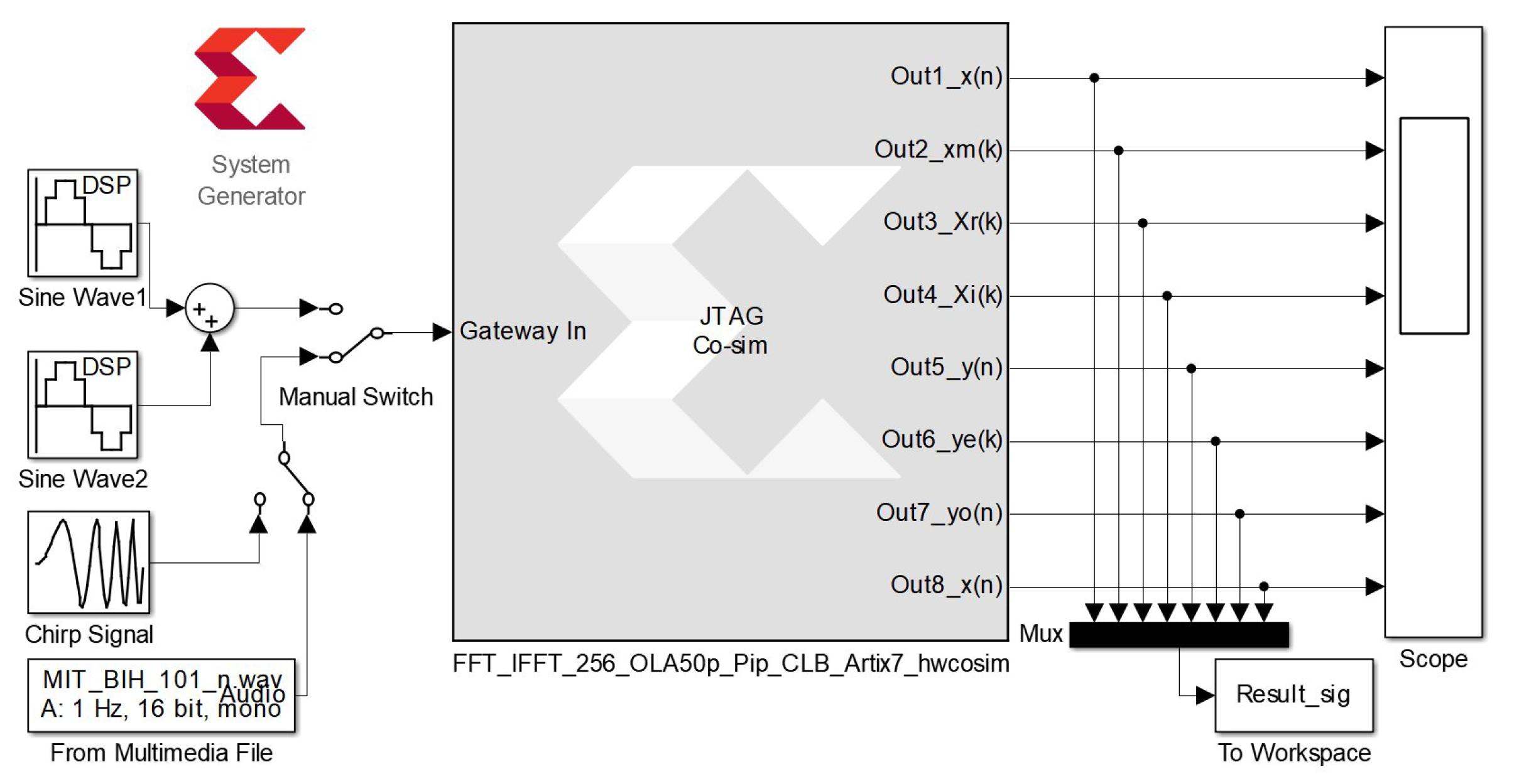
3. FPGA Implementation

The proposed architecture for the overlapping/windowing analysis, STFT/ISTFT, and overlap-add synthesis methods was implemented on FPGA using the Xilinx System Generator (XSG) interface (Figure 5). It was tested using Nexys-4 evaluation kit based on the Artix-7 XC7A100T FPGA chip. The proposed architecture was evaluated for different values of the window width ( N = 256 , 512, and 1024). The XSG-based blocks were pipelined to increase the operating frequency of this hardware architecture.

3.1. Overlapping/Windowing

The input signal was segmented into overlapping frames using a dual-port RAM (Random Access Memory) block that allows simultaneous read/write operations. The control circuit permits progressively storing (writing) the input data into memory through the first port. However, the second port allows reading overlapping signal frames using appropriate address gaps. Each resulting signal frame is then multiplied by a smoothing (Hanning) window w ( n ) , stored on a ROM (Read Only Memory) block, to obtain x ( m , n ) .

3.2. STFT/ISTFT

The STFT and ISTFT algorithms were implemented using Xilinx FFT (Fast Fourier Transform) block. When used in the analysis task (STFT), this block provides the real and imaginary parts of X ( m , k ) , as well as their corresponding frequency index k. These parts can be transformed back (ISTFT) by the same block to recover the original signal x ( m , n ) . Pipelined streaming input/output option was chosen to achieve continuous computation of the short-time Fourier transform. For complex multipliers, two options “CLB logic” and “4-multiplier structure” were tested and evaluated, in terms of used resources and operating frequency, for the FFT/IFFT size of N = 256 .

3.3. Overlap-Add Synthesis

The successive frames of y ( n ) provided by the IFFT block are separated into even and odd frames (alternate dispatching), using two dual-port RAM memories. The time-domain signal y ( n ) is progressively stored on these memories. However, a shift in the reading addresses permits separating even frames y e ( n ) from odd frames y o ( n ) .
As shown in Figure 5, the proposed architecture is very simple and easy to implement. Table 1 presents the required resources and the maximum operating frequency obtained for a 16-bit fixed-point data and a window width of N = 256 samples, as reported by the Xilinx ISE Design Suite 14.7. For the FFT/IFFT blocks, the size was also fixed to N = 256 and the “pipelined streaming input/output” option was selected to achieve continuous analysis/reconstruction. In addition, for the complex multipliers of these blocks, two options “CLB logic” and “4-multiplier structure” were compared, in terms of used resources and operating frequency. This architecture uses a small part of the used Artix-7 XC7A100T FPGA chip and can operate at more than 126.920 MHz. As expected, the “CLB logic”-based hardware architecture required more logic slices (3972 Slices, 15,822 Flip Flops, and 14,199 LUTs (Look-Up Tables)). The only DSP48E1 block was used in the windowing step. However, the “4-multiplier structure”-based architecture used fewer logic slices (1563 Slices, 6504 Flip Flops, and 4775 LUTs), but more DSP48E1 slices (12 for FFT, 12 for IFFT, and 1 for windowing). The use of the embedded multipliers allowed the best calculation performance (133.905 MHz instead of 126.920 MHz). It can be noted, to the best of our knowledge, that only two approaches [10,12] that use Xilinx system generator have been proposed in the literature, but they were not sufficiently detailed to be implemented in the present study.
Finally, the co-simulation block and its associate bitstream file were generated automatically by the XSG tool (Figure 6). During the hardware/software cosimulation, the compiled model (configuration bitstream file) was uploaded and performed on actual FPGA by taking advantage of the flexible simulation environment of MATLAB/SIMULINK.

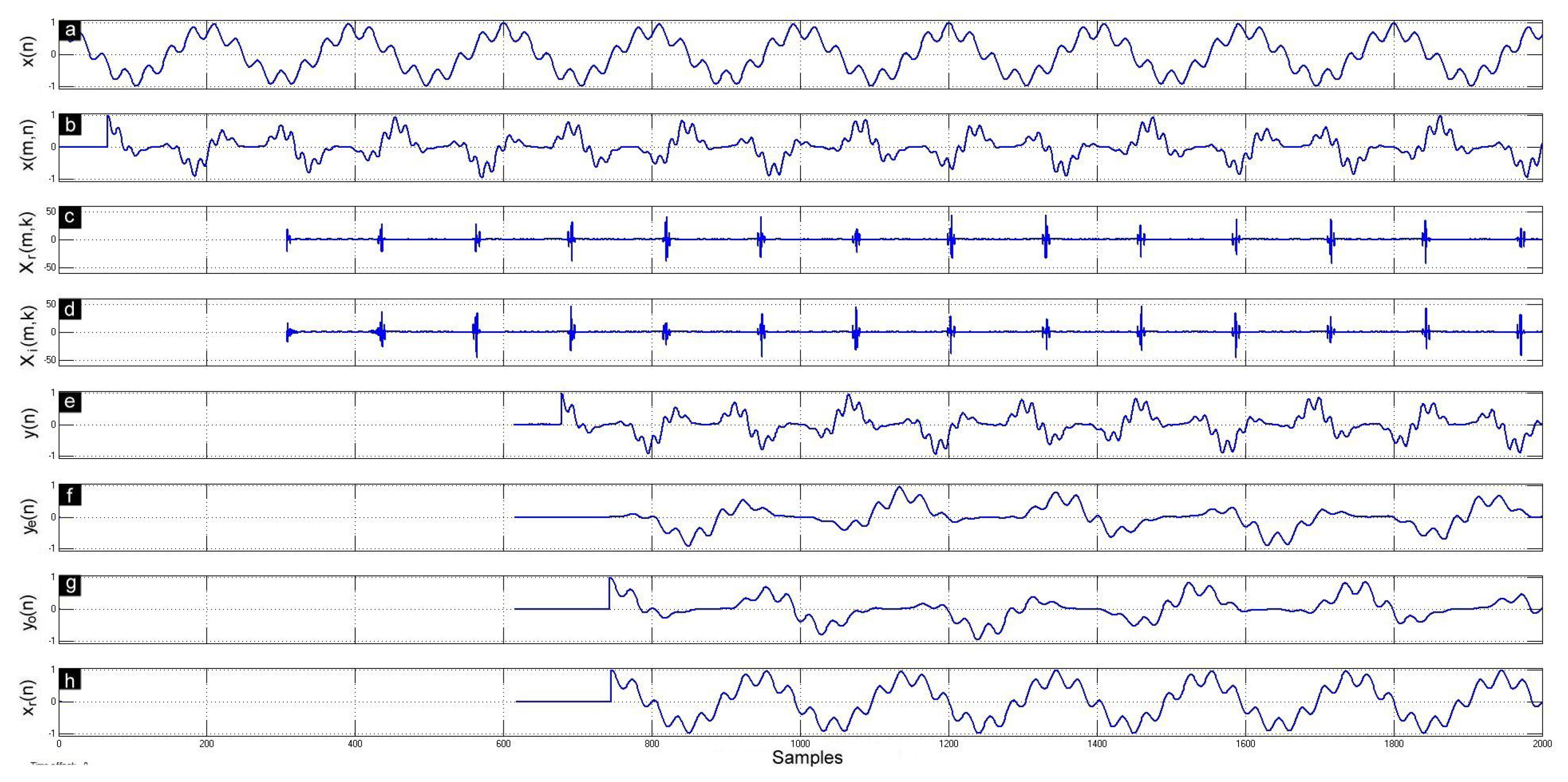
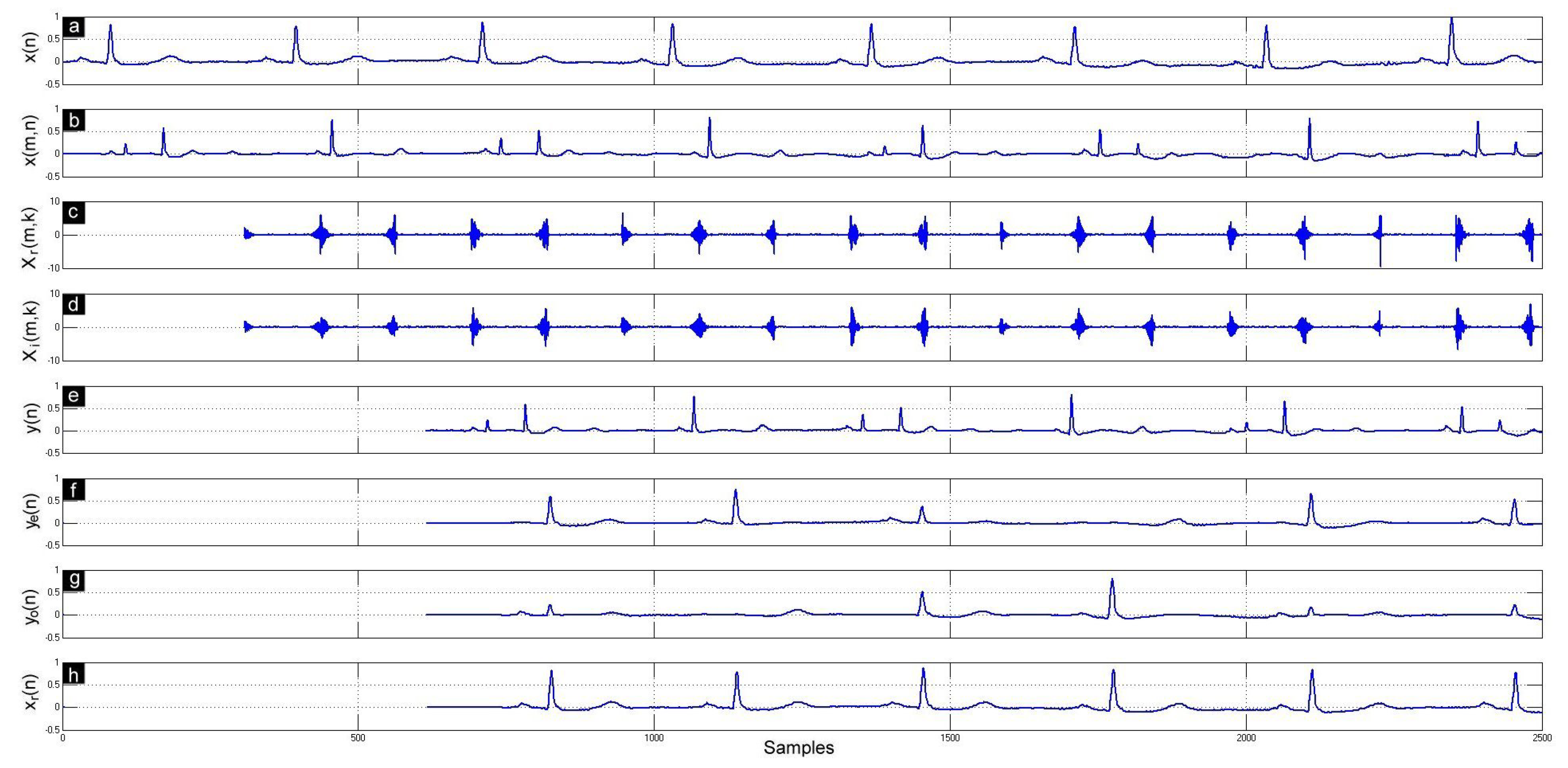
4. Results and Discussion

The proposed FPGA-based architecture was tested and evaluated, by hardware/software co-simulation (Figure 6), using artificial and actual signals. The overlapping, windowing, STFT, ISTFT, and overlap-add methods were tested and evaluated using four smoothing windows (Hanning, Triangular, Bartlett, and Hamming) of 256-sample width and 128-sample overlap (50%).

4.1. Database

A first synthetic signal was constructed from two cosine functions having different amplitudes and frequencies:
x ( n ) = 0.75 cos 2 π f 1 f s n + 0.25 cos 2 π f 2 f s n
where f 1 = f s / 200 , f 2 = f s / 30 , and f s is the sampling frequency. Thus, the lower frequency component has a period of 200 samples, slightly shorter than the windowing size ( N = 256 samples). A cosine signal having a fundamental period different from the smoothing window width allows a good evaluation of the overlap-add method, especially at frame boundaries. A second synthetic signal was obtained from a chirp signal that provides a linear swept-frequency sinusoidal in the time interval 0 n M .
x ( n ) = s i n 2 π f s f 0 + ( f 3 f 0 M ) n n
where f 0 = f s / 400 is the instantaneous frequency at n = 0 and f 3 = f s / 15 is the instantaneous frequency at n = M , where M is the simulation duration in samples.
In addition, an actual ECG (electrocardiogram) signal was taken from MIT-BIH arrhythmia database [18] that was resampled at 360 Hz.

4.2. Evaluation Tests

Three objective tests were used to evaluate the performances of the proposed FPGA-based architecture: the signal-to-noise ratio (SNR), the normalized mean square error (NMSE), and the cross-correlation (CC) measure.
The SNR evaluates the noise level in the reconstructed signal. It is defined as [13]
SNR dB = 10 log 10 n = 0 M 1 ( x ( n ) ) 2 n = 0 M 1 ( x ( n ) x r ( n ) ) 2
where x ( n ) and x r ( n ) are the original signal and the reconstructed signal, respectively. M is the size of these signal in samples.
The NMSE evaluates the distortion introduced by the analysis/synthesis steps. It is given by [19]
NMSE = n = 0 M 1 ( x ( n ) x r ( n ) ) 2 n = 0 M 1 ( x ( n ) ) 2
The CC measure evaluates the similarity between the original signal and the reconstructed signal. It is defined as [20]
CC = n = 0 M 1 [ ( x ( n ) μ o ) ( x r ( n ) μ r ) ] n = 0 M 1 ( x ( n ) μ o ) 2 k = 0 M 1 ( x r ( n ) μ r ) 2
where μ o and μ r are the mean of the original and reconstructed signal, respectively.

4.3. Results and Discussion

The proposed architecture was tested using artificial signals and actual ECG signal. As shown in Figure 7, Figure 8 and Figure 9, the original signal was correctly divided into overlapped (50%) and windowed frames. The time-domain signal was recovered after the FFT/IFFT processing. Overlap-add method was successfully implemented to provide perfect reconstruction of the original signal.
Table 2 and Table 3 show the SNR dB , NMSE, and CC values, estimated on M = 5 N = 1280 samples for various smoothing windows, using 16-bit and 32-bit fixed-point format, respectively. The perfect values ( SNR dB = , NMSE = 0 , and CC = 1 ) of these parameters were obtained by floating-format implementation in MATLAB. It can be noted that a SNR dB = 50 dB corresponds to a SNR = 10 5 , which is very large in practice. The slight difference between the theoretical performances obtained by software (MATLAB) and the practical performances obtained by hardware (XSG) are attributable to the quantization errors that occurred during the FFT/IFFT calculation steps. In fact, when the FFT/IFFT blocks were bypassed, these objective evaluation parameters were greatly improved by increasing the fixed-point data width. When the Hanning window was used with the chirp signal, the SNR reaches 85.93 dB and 182 dB for the 16-bit and 32-bit format, respectively. The NMSE reaches 2.52 × 10 9 and 6.21 × 10 19 for the 16-bit and 32-bit format, respectively.

5. Conclusions

Overlapping/windowing analysis and overlap-add synthesis methods for real-time FFT/IFFT based applications have been efficiently implemented on FPGA. The proposed FPGA-based architecture is mainly based on an adequate management of dual-port RAM memories to implement short-time based analysis/synthesis techniques. The complete system was implemented and evaluated using four smoothing windows with 50% overlap. The output signal can be considered as a perfect reconstruction of the input (original) signal. The slight difference can be explained by the quantization errors, mainly in the FFT/IFFT blocks.
In the future, this architecture will be extended to other overlap rates. It will also be incorporated to more advanced signal processing systems as speech enhancement and feature extraction.

Funding

This research was funded by the Natural Sciences and Engineering Research Council of Canada.

Conflicts of Interest

The author declare no conflict of interest.

References

  1. Gade, S.; Gram-Hansen, K. Non-Stationary Signal Analysis Using Wavelet Transform, Short-Time Fourier Transform and Wigner-Ville Distribution; Technical Reviews 2; Brüel & Kjær: Nærum, Denmark, 1996. [Google Scholar]
  2. Boll, S.F. Suppression of Acoustic Noise in Speech Using Spectral Subtraction. IEEE Trans. Acoust. Speech Signal Process. 1979, 27, 113–120. [Google Scholar] [CrossRef] [Green Version]
  3. Reynolds, D.; Rose, R. Robust Test-Independent Speaker Identification Using Gaussian Mixture Speaker Models. IEEE Trans. Speech Audio Process. 1995, 3, 72–83. [Google Scholar] [CrossRef] [Green Version]
  4. Tzanetakis, G.; Cook, P. Musical genre classification of audio signals. IEEE Trans. Speech Audio Process. 2002, 10, 293–302. [Google Scholar] [CrossRef]
  5. Wacker, M.; Witte, H. Time-frequency techniques in biomedical signal analysis: A tutorial review of similarities and differences. Methods Inf. Med. 2013, 52, 279–296. [Google Scholar] [PubMed]
  6. Mateo, C.; Talavera, J. Short-time Fourier transform with the window size fixed in the frequency domain. Digit. Signal Process. Rev. J. 2018, 77, 13–21. [Google Scholar] [CrossRef]
  7. Allen, J.B.; Rabiner, L.R. A unified approach to short-time Fourier analysis and synthesis. Proc. IEEE 1977, 65, 1558–1564. [Google Scholar] [CrossRef]
  8. Crochiere, R. A weighted overlap-add method of short-time Fourier analysis/Synthesis. IEEE Trans. Acoust. Speech Signal Process. 1980, 28, 99–102. [Google Scholar] [CrossRef]
  9. George, E.B.; Smith, M.J.T. Speech analysis/synthesis and modification using an analysis-by-synthesis/overlap-add sinusoidal model. IEEE Trans. Speech Audio Process. 1997, 5, 389–406. [Google Scholar] [CrossRef]
  10. Whittington, J.; Deo, K.; Kleinschmidt, T.; Mason, M. FPGA implementation of spectral subtraction for in-car speech enhancement and recognition. In Proceedings of the 2nd International Conference on Signal Processing and Communication Systems, ICSPCS 2008, Gold Coast, Australia, 13–15 December 2008. [Google Scholar]
  11. Bahoura, M.; Ezzaidi, H. Implementation of spectral subtraction method on FPGA using high-level programming tool. In Proceedings of the 24th International Conference on Microelectronics (ICM), Algiers, Algeria, 17–20 December 2012; pp. 1–4. [Google Scholar]
  12. Amornwongpeeti, S.; Ono, N.; Ekpanyapong, M. Design of FPGA-based rapid prototype spectral subtraction for hands-free speech applications. In Proceedings of the Signal and Information Processing Association Annual Summit and Conference (APSIPA), Asia-Pacific, Chiang Mai, Thailand, 9–12 December 2014; pp. 1–6. [Google Scholar]
  13. Bahoura, M. Pipelined Architecture of Multi-Band Spectral Subtraction Algorithm for Speech Enhancement. Electronics 2017, 6, 73. [Google Scholar] [CrossRef] [Green Version]
  14. Wassi, G.; Iloga, S.; Romain, O.; Granado, B. FPGA-based real-time MFCC extraction for automatic audio indexing on FM broadcast data. In Proceedings of the 2015 Conference on Design and Architectures for Signal and Image Processing (DASIP), Krakow, Poland, 23–25 September 2015; pp. 1–6. [Google Scholar]
  15. Lin, B.S.; Yen, T.S. An FPGA-based rapid wheezing detection system. Int. J. Environ. Res. Public Health 2014, 11, 1573–1593. [Google Scholar] [CrossRef] [PubMed]
  16. Bahoura, M. FPGA Implementation of Blue Whale Calls Classifier Using High-Level Programming Tool. Electronics 2016, 5, 8. [Google Scholar] [CrossRef] [Green Version]
  17. Boujelben, O.; Bahoura, M. Efficient FPGA-based architecture of an automatic wheeze detector using a combination of MFCC and SVM algorithms. J. Syst. Archit. 2018, 88, 54–64. [Google Scholar] [CrossRef]
  18. Goldberger, A.L.; Amaral, L.A.N.; Glass, L.; Hausdorff, J.M.; Ivanov, P.C.; Mark, R.G.; Mietus, J.E.; Moody, G.B.; Peng, C.K.; Stanley, H.E. PhysioBank, PhysioToolkit, and PhysioNet: Components of a New Research Resource for Complex Physiologic Signals. Circulation 2000, 101, e215–e220. [Google Scholar] [CrossRef] [PubMed] [Green Version]
  19. Berti, E.; Chiaraluce, F.; Evans, N.E.; McKee, J.J. Reduction of Walsh-transformed electrocardiograms by double logarithmic coding. IEEE Trans. Biomed. Eng. 2000, 47, 1543–1547. [Google Scholar] [CrossRef] [PubMed]
  20. Chen, J.; Itoh, S. A Wavelet Transform-Based ECG Compression Method Guaranteeing Desired Signal Quality. IEEE Trans. Biomed. Eng. 1998, 45, 1414–1419. [Google Scholar] [CrossRef] [PubMed]
Figure 1. Bloc diagram of the overlapping, windowing, STFT, ISTFT, and overlap-add methods.
Electronics 08 01533 g001
Figure 2. Illustration of the overlap-add method (red lines) using Hanning, Triangular, Bartlett, and Hamming windows (blues lines) of 32-sample width and 16-sample overlap (50%).
Electronics 08 01533 g002
Figure 3. Illustration of the overlap-add method (red lines) using Hanning window of different widths ( N = 50 , 128, 150, 256, 400, and 512), but a fixed shift ( L = N / 2 ) that corresponds to an overlap rate of 50%.
Electronics 08 01533 g003
Figure 4. Illustration of the overlap-add method (red lines) using Hanning window of a fixed width ( N = 256 ), but different shift values L. For example, a frame shift of L = 32 samples corresponds to an overlap rate of (256 − 32)/256 = 87.5%
Electronics 08 01533 g004
Figure 5. Hardware architecture of the overlapping, windowing, STFT, ISTFT, and overlap-add methods implemented using Xilinx System Generator (XSG) blockset.
Electronics 08 01533 g005
Figure 6. Hardware/software co-simulation corresponding to the diagram of Figure 5.
Electronics 08 01533 g006
Figure 7. Visualization of the intermediate signals obtained during different calculation stages: (a) original cosine mixture signal x ( n ) ; (b) successive windowed frames x ( m , n ) using Hanning function; (c) real parts X r ( m , k ) of their corresponding STFT; (d) imaginary parts X i ( m , k ) of their corresponding STFT; (e) overlapped and windowed signal y ( n ) obtained by back transformation ISTFT; (f) non-overlapped even frames extraction y e ( n ) ; (g) non-overlapped odd frames extraction y o ( n ) ; and (h) reconstructed signal x r ( n ) .
Electronics 08 01533 g007
Figure 8. Same as Figure 7 but using a chirp signal.
Electronics 08 01533 g008
Figure 9. Same as Figure 7 but using an actual ECG signal from record 101 of MIT-BIH database.
Electronics 08 01533 g009
Table 1. Resource utilization and maximum operating frequency of the proposed architecture obtained for the Artix-7 XC7A100T chip with two FFT/IFFT implementation options: “CLB logic” and “4-multiplier structure” of the complex multipliers. CLB, Configurable Logic Block; LUT, Look-Up Table; IOB, Input/Output Block; RAMB, Random Access Memory Block; DSP18E1, Digital Signal Processing slice.
ArchitectureCLB Logic4-Multiplier
Resource utilization
 Slices (15,850)3972 (25.1%)1563 (9.9%)
 Flip Flops (126,800)15,822 (12.5%)6504 (5.3%)
 LUTs (63,400)14,199 (22.4%)4775 (7.5%)
 Bonded IOBs (210)33 (15.7%)33 (15.0%)
 RAMB18E1s (270)6 (2.2%)6 (2.2%)
 DSP48E1s (240)1 (0.4%)25 (10.4%)
Maximum Operating Frequency126.920 MHz133.905 MHz
Table 2. Signal-to-noise ratio ( SNR dB ), normalized mean square error (NMSE), and cross-correlation (CC) parameters obtained by the proposed architecture using 16-bit fixed-point format.
Cosine Mixture Chirp ECG
Window SNR dB NMSECC SNR dB NMSECC SNR dB NMSECC
Hanning 68.31 1.47 × 10 7 0.999999 70.10 0.97 × 10 7 0.999999 50.07 9.83 × 10 6 0.999995
Triangular 64.13 3.86 × 10 7 0.999999 66.55 2.21 × 10 7 0.999999 50.63 9.62 × 10 6 0.999995
Bratlett 65.32 2.93 × 10 7 0.999999 67.15 1.92 × 10 7 0.999999 50.34 9.24 × 10 6 0.999995
Hamming 64.84 3.28 × 10 7 0.999999 67.03 1.98 × 10 7 0.999999 51.01 7.92 × 10 6 0.999996
Table 3. Same as Table 2 but using 32-bit fixed-point format.
Cosine Mixture Chirp ECG
Window SNR dB NMSECC SNR dB NMSECC SNR dB NMSECC
Hanning 68.25 1.49 × 10 7 0.999999 70.31 0.93 × 10 7 0.999999 50.04 9.91 × 10 6 0.999995
Triangular 63.98 3.99 × 10 7 0.999999 66.54 2.21 × 10 7 0.999999 50.19 9.55 × 10 6 0.999995
Bratlett 65.17 3.04 × 10 7 0.999999 67.19 1.91 × 10 7 0.999999 50.33 9.27 × 10 6 0.999995
Hamming 64.82 3.29 × 10 7 0.999999 66.98 2.01 × 10 7 0.999999 50.88 78.18 × 10 6 0.999995

