Effects of the Body Wearable Sensor Position on the UWB Localization Accuracy


Abstract
:
1. Introduction
2. Related Work
3. UWB Interaction with the Human Body
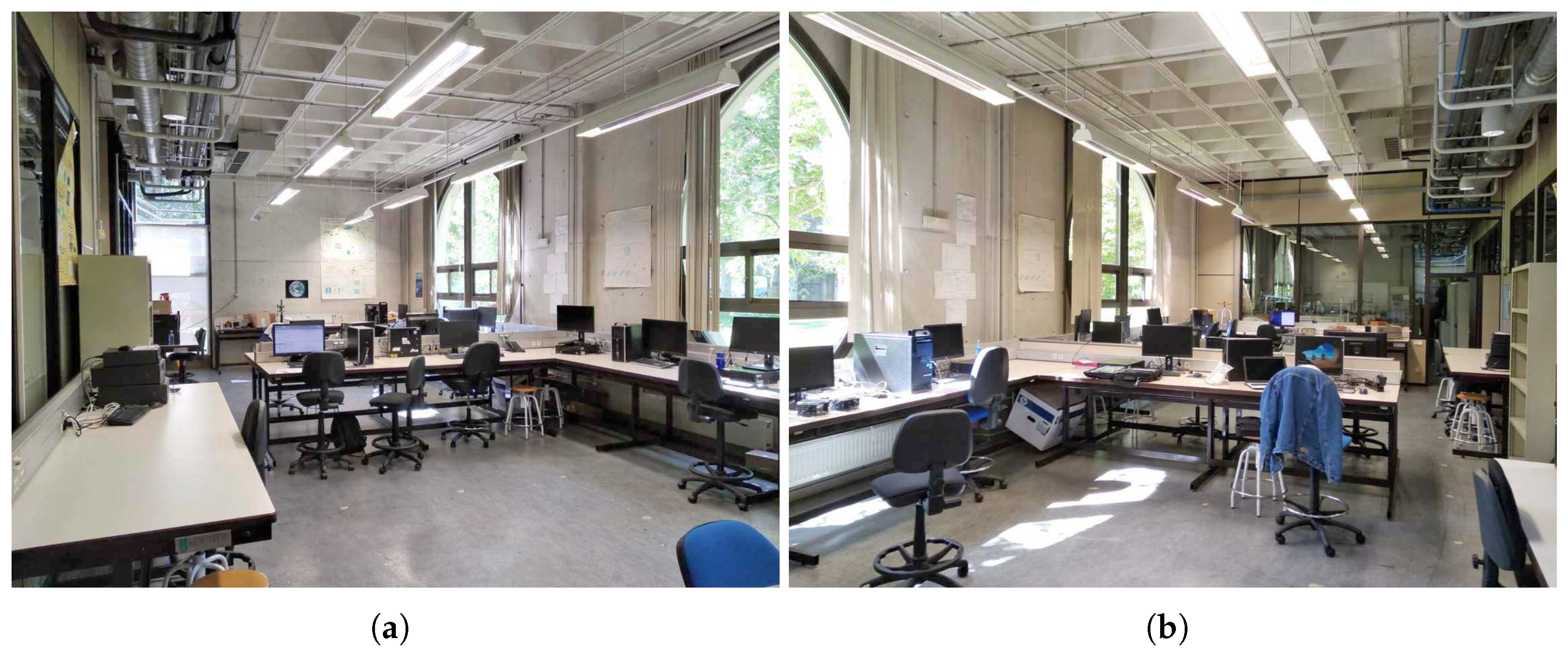
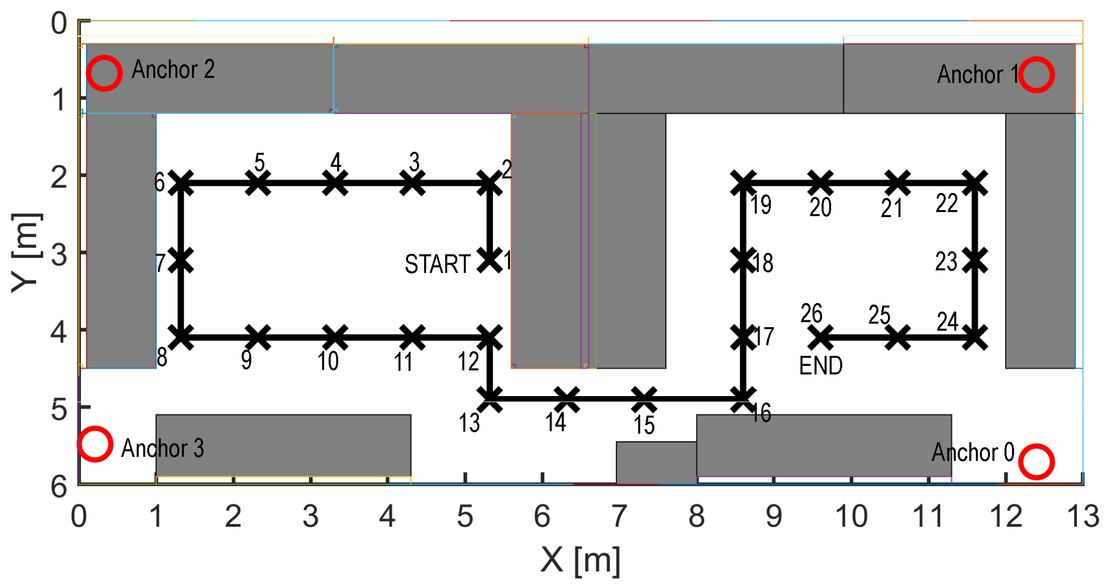
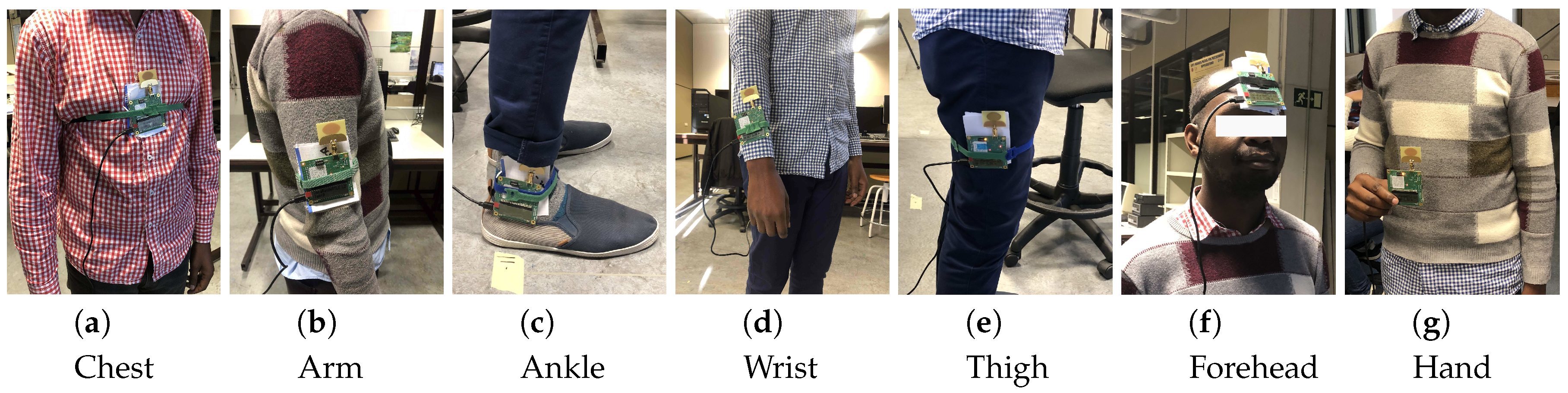
4. Experimental Setup
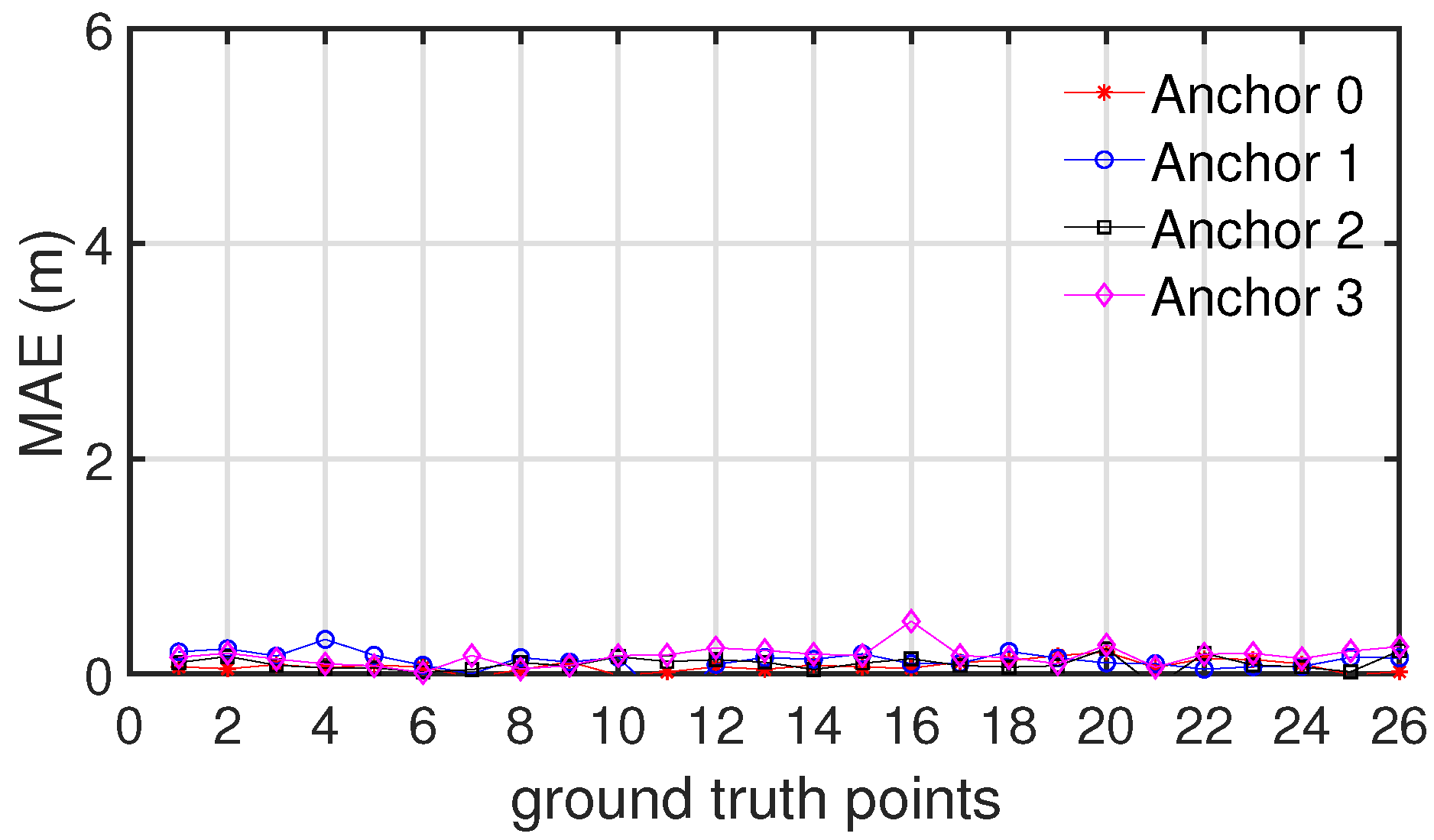
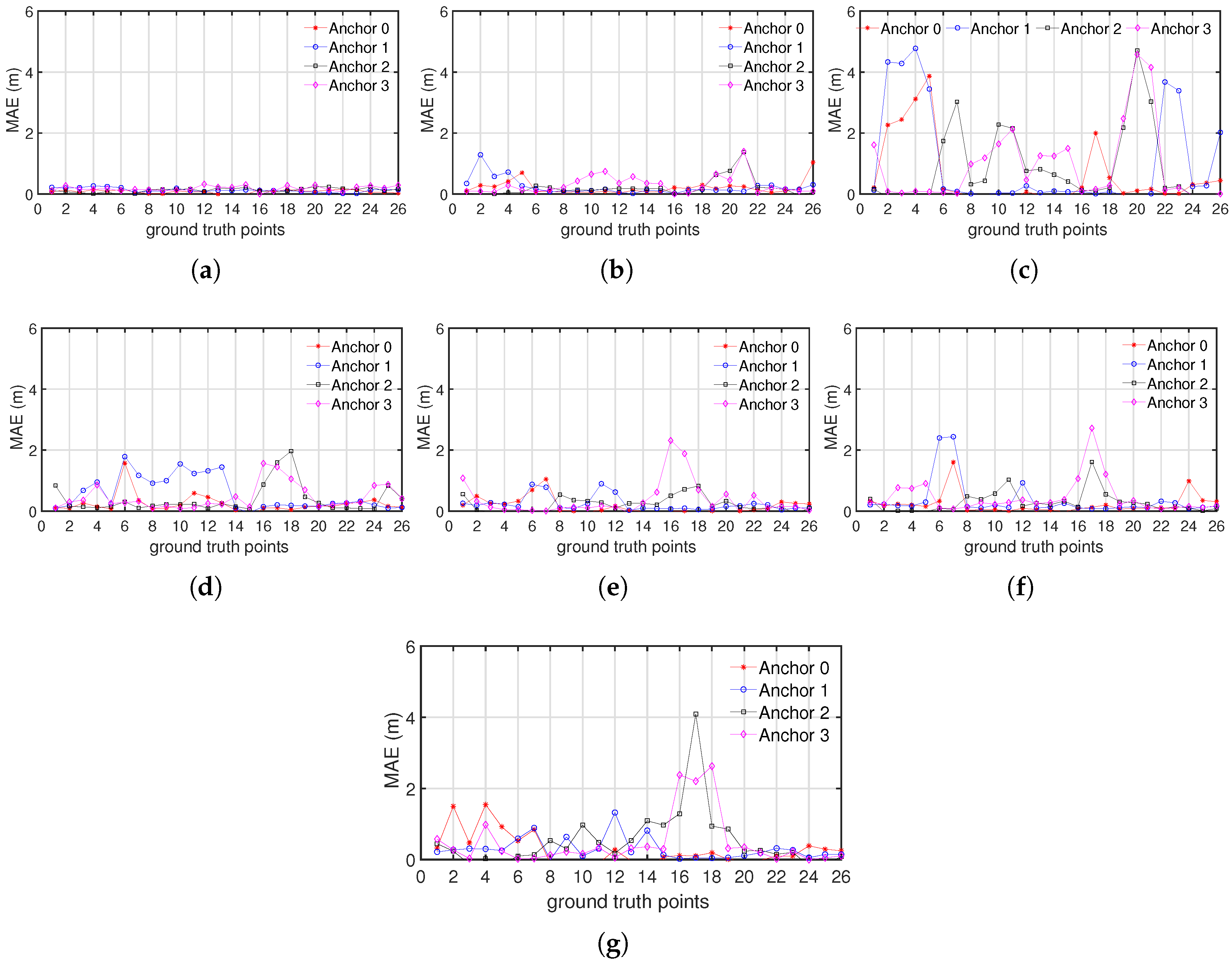
5. Analysis of the Ranging Performance
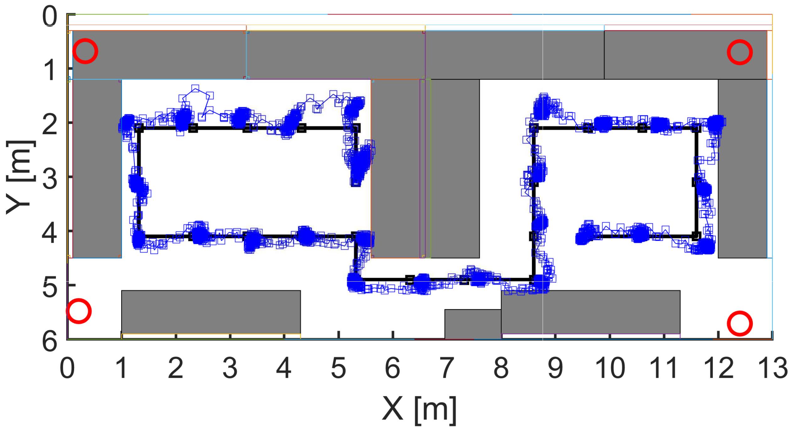
6. Analyzing of the Positioning Performance
- Smoothing: We applied a moving average filter to each position component. The length of the window was empirically set to 4 s.
- Filtering: A moving variance with window length of 4 s was set to minimize the number of outliers in the position estimation.
- A k-means clustering was applied to the filtered estimates to determine the ground-truth positions (extorted from the obtained centroids).
7. Results and Discussion
8. Conclusions
Author Contributions
Funding
Conflicts of Interest
References
- Hayward, J.; Chansin, G.; Zervos, H. Wearable Technology 2017–2027: Technologies, Markets, Forecast; IDTechEx Research: 2017. Available online: http://www.idtechex.com/en/research-report/wearable-technology-2017-2027-markets-players-forecasts/536 (accessed on 11 September 2019).
- Liang, T.; Yuan, Y. Wearable medical monitoring systems based on wireless networks: A Review. IEEE Sens. J. 2016. [Google Scholar] [CrossRef]
- Buchem, I.; Merceron, A.; Kreutel, J.; Haesner, M.; Steinert, A. Gamification designs in Wearable Enhanced Learning for healthy ageing. In Proceedings of the 2015 International Conference on Interactive Mobile Communication Technologies and Learning (IMCL), Thessaloniki, Greece, 19–20 November 2015; pp. 9–15. [Google Scholar] [CrossRef]
- Ferreira, B.V.; Serejo, G.; Ferreira, M.R.; Ferreira, D.F.; Cardoso, L.; Yoshidome, E.; Arruda, H.; Lira, W.; Ferreira, J.; Carvalho, E.; et al. Wearable computing for railway environments: Proposal and evaluation of a safety solution. IET Intell. Transp. Syst. 2017, 11, 319–325. [Google Scholar] [CrossRef]
- De Cillis, F.; Faramondi, L.; Inderst, F.; Marsella, S.; Marzoli, M.; Pascucci, F.; Setola, R. Hybrid Indoor Positioning System for First Responders. IEEE Trans. Syst. Man Cybern. Syst. 2017. [Google Scholar] [CrossRef]
- Moayeri, N.; Mapar, J.; Tompkins, S.; Pahlavan, K. Emerging opportunities for localization and tracking [Guest Editorial]. IEEE Wirel. Commun. 2011, 18, 8–9. [Google Scholar] [CrossRef]
- Mukhopadhyay, S.C. Wearable Sensors for Human Activity Monitoring: A Review. IEEE Sens. J. 2015, 15, 1321–1330. [Google Scholar] [CrossRef]
- Lopez-Nava, I.H.; Munoz-Melendez, A. Wearable Inertial Sensors for Human Motion Analysis: A Review. IEEE Sens. J. 2016, 16, 7821–7834. [Google Scholar] [CrossRef]
- Ramadhan, A. Wearable Smart System for Visually Impaired People. Sensors 2018, 18, 843. [Google Scholar] [CrossRef]
- Iosa, M.; Picerno, P.; Paolucci, S.; Morone, G. Wearable inertial sensors for human movement analysis. Expert Rev. Med. Devices 2016, 13, 641–659. [Google Scholar] [CrossRef]
- Milici, S.; Lazaro, A.; Villarino, R.; Girbau, D.; Magnarosa, M. Wireless Wearable Magnetometer-Based Sensor for Sleep Quality Monitoring. IEEE Sens. J. 2018, 18, 2145–2152. [Google Scholar] [CrossRef]
- Bertuletti, S.; Cereatti, A.; Comotti, D.; Caldara, M.; Della Croce, U. Static and Dynamic Accuracy of an Innovative Miniaturized Wearable Platform for Short Range Distance Measurements for Human Movement Applications. Sensors 2017, 17, 1492. [Google Scholar] [CrossRef]
- Puricer, P.; Kovar, P. Technical Limitations of GNSS Receivers in Indoor Positioning. In Proceedings of the 2007 17th International Conference Radioelektronika, Brno, Czech Republic, 24–25 April 2007; pp. 1–5. [Google Scholar] [CrossRef]
- Kułakowski, P.; Vales-Alonso, J.; Egea-López, E.; Ludwin, W.; García-Haro, J. Angle-of-arrival localization based on antenna arrays for wireless sensor networks. Comput. Electr. Eng. 2010, 36, 1181–1186. [Google Scholar] [CrossRef]
- Lanzisera, S.; Zats, D.; Pister, K.S.J. Radio Frequency Time-of-Flight Distance Measurement for Low-Cost Wireless Sensor Localization. IEEE Sens. J. 2011, 11, 837–845. [Google Scholar] [CrossRef]
- Diono, M.; Rachmana, N. Indoor positioning system based on received signal strength (RSS) fingerprinting: Case in Politeknik Caltex Riau. In Proceedings of the 2014 8th International Conference on Telecommunication Systems Services and Applications (TSSA), Kuta, Indonesia, 23–24 October 2014; pp. 1–5. [Google Scholar]
- He, J.; Geng, Y.; Liu, F.; Xu, C. CC-KF: Enhanced TOA Performance in Multipath and NLOS Indoor Extreme Environment. IEEE Sens. J. 2014, 14, 3766–3774. [Google Scholar] [CrossRef]
- Ma, H.; Wang, K. Fusion of RSS and Phase Shift Using the Kalman Filter for RFID Tracking. IEEE Sens. J. 2017, 17, 3551–3558. [Google Scholar] [CrossRef]
- Xu, C.; Ji, M.; Qi, Y.; Zhou, X. MCC-CKF: A Distance Constrained Kalman Filter Method for Indoor TOA Localization Applications. Electronics 2019, 8, 478. [Google Scholar] [CrossRef]
- Pak, J.M.; Ahn, C.K.; Shmaliy, Y.S.; Lim, M.T. Improving Reliability of Particle Filter-Based Localization in Wireless Sensor Networks via Hybrid Particle/FIR Filtering. IEEE Trans. Ind. Inform. 2015, 11, 1089–1098. [Google Scholar] [CrossRef]
- Akiyama, T.; Ohashi, H.; Sato, A.; Nakahara, G.; Yamasaki, K. Pedestrian dead reckoning using adaptive particle filter to human moving mode. In Proceedings of the 2013 International Conference on Indoor Positioning and Indoor Navigation (IPIN), Montbeliard, France, 28–31 October 2013; pp. 1–7. [Google Scholar]
- Ur Rehman, S.; Liu, R.; Zhang, H.; Liang, G.; Fu, Y.; Qayoom, A. Localization of Moving Objects Based on RFID Tag Array and Laser Ranging Information. Electronics 2019, 8, 887. [Google Scholar] [CrossRef]
- Jimenez Ruiz, A.R.; Seco Granja, F. Comparing Ubisense, BeSpoon, and DecaWave UWB Location Systems: Indoor Performance Analysis. IEEE Trans. Instrum. Meas. 2017, 66, 2106–2117. [Google Scholar] [CrossRef]
- Apple Invents iBeacon Version 2 Using Ultra-Wide Band Radio Technology. Available online: https://www.patentlyapple.com/patently-apple/2019/01/apple-invents-ibeacon-version-2-using-ultra-wide-band-radio-technology.html (accessed on 4 September 2019).
- Lazzari, F.; Buffi, A.; Nepa, P.; Lazzari, S. Numerical Investigation of an UWB Localization Technique for Unmanned Aerial Vehicles in Outdoor Scenarios. IEEE Sens. J. 2017, 17, 2896–2903. [Google Scholar] [CrossRef]
- Tiemann, J.; Schweikowski, F.; Wietfeld, C. Design of an UWB indoor-positioning system for UAV navigation in GNSS-denied environments. In Proceedings of the 2015 International Conference on Indoor Positioning and Indoor Navigation (IPIN), Banff, AB, Canada, 13–16 October 2015; pp. 1–7. [Google Scholar] [CrossRef]
- Perakis, H.; Gikas, V. Evaluation of Range Error Calibration Models for Indoor UWB Positioning Applications. In Proceedings of the 2018 International Conference on Indoor Positioning and Indoor Navigation (IPIN), Nantes, France, 24–27 October 2018; pp. 206–212. [Google Scholar] [CrossRef]
- Ferreira, A.; Fernandes, D.; Catarino, A.; Monteiro, J. Performance Analysis of ToA-Based Positioning Algorithms for Static and Dynamic Targets with Low Ranging Measurements. Sensors 2017, 17, 1915. [Google Scholar] [CrossRef]
- Tian, Q.; Wang, K.I.K.; Salcic, Z. Human Body Shadowing Effect on UWB-Based Ranging System for Pedestrian Tracking. IEEE Trans. Instrum. Meas. 2018. [Google Scholar] [CrossRef]
- He, J.; Geng, Y.; Pahlavan, K. Toward Accurate Human Tracking: Modeling Time-of-Arrival for Wireless Wearable Sensors in Multipath Environment. IEEE Sens. J. 2014, 14, 3996–4006. [Google Scholar] [CrossRef]
- Bharadwaj, R.; Koul, S.K. Experimental Analysis of Ultra-Wideband Body-to-Body Communication Channel Characterization in an Indoor Environment. IEEE Trans. Antennas Propag. 2019, 67, 1779–1789. [Google Scholar] [CrossRef]
- Otim, T.; Bahillo, A.; Diez, L.E.; Lopez-Iturri, P.; Falcone, F. FDTD and Empirical Exploration of Human Body and UWB Radiation Interaction on TOF Ranging. IEEE Antennas Wirel. Propag. Lett. 2019, 18, 1119–1123. [Google Scholar] [CrossRef]
- Geng, Y.; Wan, Y.; He, J.; Pahlavan, K. An empirical channel model for the effect of human body on ray tracing. In Proceedings of the 2013 IEEE 24th Annual International Symposium on Personal, Indoor, and Mobile Radio Communications (PIMRC), London, UK, 8–9 September 2013; pp. 47–52. [Google Scholar] [CrossRef]
- Kilic, Y.; Ali, A.J.; Meijerink, A.; Bentum, M.J.; Scanlon, W.G. The effect of human-body shadowing on indoor UWB TOA-based ranging systems. In Proceedings of the 2012 9th Workshop on Positioning, Navigation and Communication, Dresden, Germany, 15–16 March 2012; pp. 126–130. [Google Scholar] [CrossRef]
- Irahhauten, Z.; Dacuna, J.; Janssen, G.; Nikookar, H. UWB Channel Measurements and Results for Wireless Personal Area Networks Applications. In Proceedings of the European Conference on Wireless Technology, CNIT la Defense, Paris, France, 3–7 October 2005; pp. 209–212. [Google Scholar] [CrossRef]
- Zhang, R.; Cai, L.; He, S.; Dong, X.; Pan, J. Modeling, validation and performance evaluation of body shadowing effect in ultra-wideband networks. Phys. Commun. 2009, 2, 237–247. [Google Scholar] [CrossRef]
- Otim, T.; Bahillo, A.; Diez, L.E.; Lopez-Iturri, P.; Falcone, F. Impact of Body Wearable Sensor Positions on UWB Ranging. IEEE Sens. J. 2019. [Google Scholar] [CrossRef]
- Gengt, Y. Modeling the effect of human body on TOA ranging for indoor human tracking with wrist mounted sensor. In Proceedings of the 16th International Symposium on Wireless Personal Multimedia Communications (WPMC), Atlantic City, NJ, USA, 24–27 June 2013; pp. 1–6. [Google Scholar]
- He, J.; Geng, Y.; Pahlavan, K. Modeling indoor TOA ranging error for body mounted sensors. In Proceedings of the 2012 IEEE 23rd International Symposium on Personal, Indoor and Mobile Radio Communications—(PIMRC), Sydney, Australia, 9–12 September 2012; pp. 682–686. [Google Scholar] [CrossRef]
- Pourhomayoun, M.; Jin, Z.; Fowler, M.L. Accurate Localization of In-Body Medical Implants Based on Spatial Sparsity. IEEE Trans. Biomed. Eng. 2014, 61, 590–597. [Google Scholar] [CrossRef]
- Dove, I. Analysis of Radio Propagation Inside the Human Body for in-Body Localization Purposes. Master’s Thesis, University of Twente, Enschede, The Netherlands, 2014. [Google Scholar]
- Christ, A.; Klingenbock, A.; Samaras, T.; Goiceanu, C.; Kuster, N. The dependence of electromagnetic far-field absorption on body tissue composition in the frequency range from 300 MHz to 6 GHz. IEEE Trans. Microw. Theory Tech. 2006, 54, 2188–2195. [Google Scholar] [CrossRef]
- Kuster, N.; Santomaa, V.; Drossos, A. The dependence of electromagnetic energy absorption upon human head tissue composition in the frequency range of 300–3000 MHz. IEEE Trans. Microw. Theory Tech. 2000, 48, 1988–1995. [Google Scholar] [CrossRef]
- Jiménez, A.R.; Seco, F. Comparing Decawave and Bespoon UWB location systems: indoor/outdoor performance analysis. In Proceedings of the 2016 International Conference on Indoor Positioning and Indoor Navigation (IPIN), Madrid, Spain, 4–7 October 2016; pp. 1–8. [Google Scholar]
- Understanding and Using the DecaRangeRTLS ARM Source Code—Version 2.1. Available online: https://www.coursehero.com/file/35541696/DecaRangeRTLS-ARM-Source-Code-Guidepdf/ (accessed on 11 November 2019).
- Zasowski, T.; Meyer, G.; Althaus, F.; Wittneben, A. UWB signal propagation at the human head. IEEE Trans. Microw. Theory Tech. 2006, 54, 1836–1845. [Google Scholar] [CrossRef]
- Schmitt, S.; Adler, S.; Kyas, M. The effects of human body shadowing in RF-based indoor localization. In Proceedings of the 2014 International Conference on Indoor Positioning and Indoor Navigation (IPIN), Busan, Korea, 27–30 October 2014; pp. 307–313. [Google Scholar]
- Diez, L.E.; Bahillo, A.; Otim, T.; Otegui, J. Step Length Estimation Using UWB Technology: A Preliminary Evaluation. In Proceedings of the 2018 International Conference on Indoor Positioning and Indoor Navigation (IPIN), Nantes, France, 24–27 October 2018; pp. 1–8. [Google Scholar] [CrossRef]
- Ridolfi, M.; Vandermeeren, S.; Defraye, J.; Steendam, H.; Gerlo, J.; De Clercq, D.; Hoebeke, J.; De Poorter, E. Experimental Evaluation of UWB Indoor Positioning for Sport Postures. Sensors 2018, 18, 168. [Google Scholar] [CrossRef] [PubMed] [Green Version]
- Bharadwaj, R.; Parini, C.; Alomainy, A. Experimental Investigation of 3-D Human Body Localization Using Wearable Ultra-Wideband Antennas. IEEE Trans. Antennas Propag. 2015, 63, 5035–5044. [Google Scholar] [CrossRef]


| Tissue | Thorax | Limbs | Head |
|---|---|---|---|
| Skin | 1.4–2.6 | 0.6–2.0 | 0.5–2 |
| Fat | 0.6–15.0 | 0.4–20.6 | 1–2 |
| Muscle | 0.0–30.0 | 0.0–3.0 | 0–4 |
| Bone | 5.6–6.6 | - | 1–10 |
| Anchor | X (cm) | Y (cm) | Z (cm) |
|---|---|---|---|
| Anchor 0 | 1240 | 571 | 170 |
| Anchor 1 | 1240 | 70 | 173 |
| Anchor 2 | 548 | 33 | 172 |
| Anchor 3 | 68 | 21 | 172 |
| Ankle | Thigh | Forehead | Hand | Arm | Chest | Wrist | |
|---|---|---|---|---|---|---|---|
| H | 15 | 70 | 177 | 120 | 130 | 130 | 90 |
| Ankle | Thigh | Forehead | Hand | Arm | Chest | Wrist | |
|---|---|---|---|---|---|---|---|
| SD | 50 | 60 | 10 | 30 | 50 | 130 | 20 |
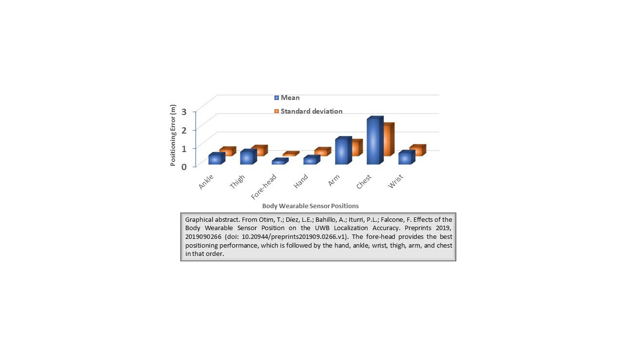
| Wearable Location | Mean | Median | P90 | SD |
|---|---|---|---|---|
| Tripod | 0.12 | 0.10 | 0.21 | 0.06 |
| Forehead | 0.20 | 0.21 | 0.35 | 0.11 |
| Hand | 0.35 | 0.26 | 0.62 | 0.33 |
| Ankle | 0.50 | 0.36 | 0.97 | 0.36 |
| Wrist | 0.62 | 0.52 | 1.14 | 0.48 |
| Thigh | 0.68 | 0.57 | 1.46 | 0.45 |
| Arm | 1.36 | 1.26 | 2.47 | 0.77 |
| Chest | 2.46 | 2.55 | 4.04 | 1.66 |
© 2019 by the authors. Licensee MDPI, Basel, Switzerland. This article is an open access article distributed under the terms and conditions of the Creative Commons Attribution (CC BY) license (http://creativecommons.org/licenses/by/4.0/).
Share and Cite
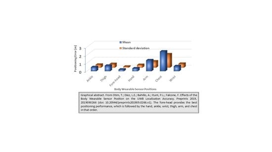
Otim, T.; Díez, L.E.; Bahillo, A.; Lopez-Iturri, P.; Falcone, F. Effects of the Body Wearable Sensor Position on the UWB Localization Accuracy. Electronics 2019, 8, 1351. https://doi.org/10.3390/electronics8111351
Otim T, Díez LE, Bahillo A, Lopez-Iturri P, Falcone F. Effects of the Body Wearable Sensor Position on the UWB Localization Accuracy. Electronics. 2019; 8(11):1351. https://doi.org/10.3390/electronics8111351
Chicago/Turabian StyleOtim, Timothy, Luis E. Díez, Alfonso Bahillo, Peio Lopez-Iturri, and Francisco Falcone. 2019. "Effects of the Body Wearable Sensor Position on the UWB Localization Accuracy" Electronics 8, no. 11: 1351. https://doi.org/10.3390/electronics8111351