Decentralized Power Management for Electrical Power Systems in More Electric Aircrafts


Abstract
:1. Introduction
2. Contributions of Present Work
3. Decentralized Power Management for an MEA EPS
3.1. Limitations of Centralized Power Management
3.2. Decentralized Power Management
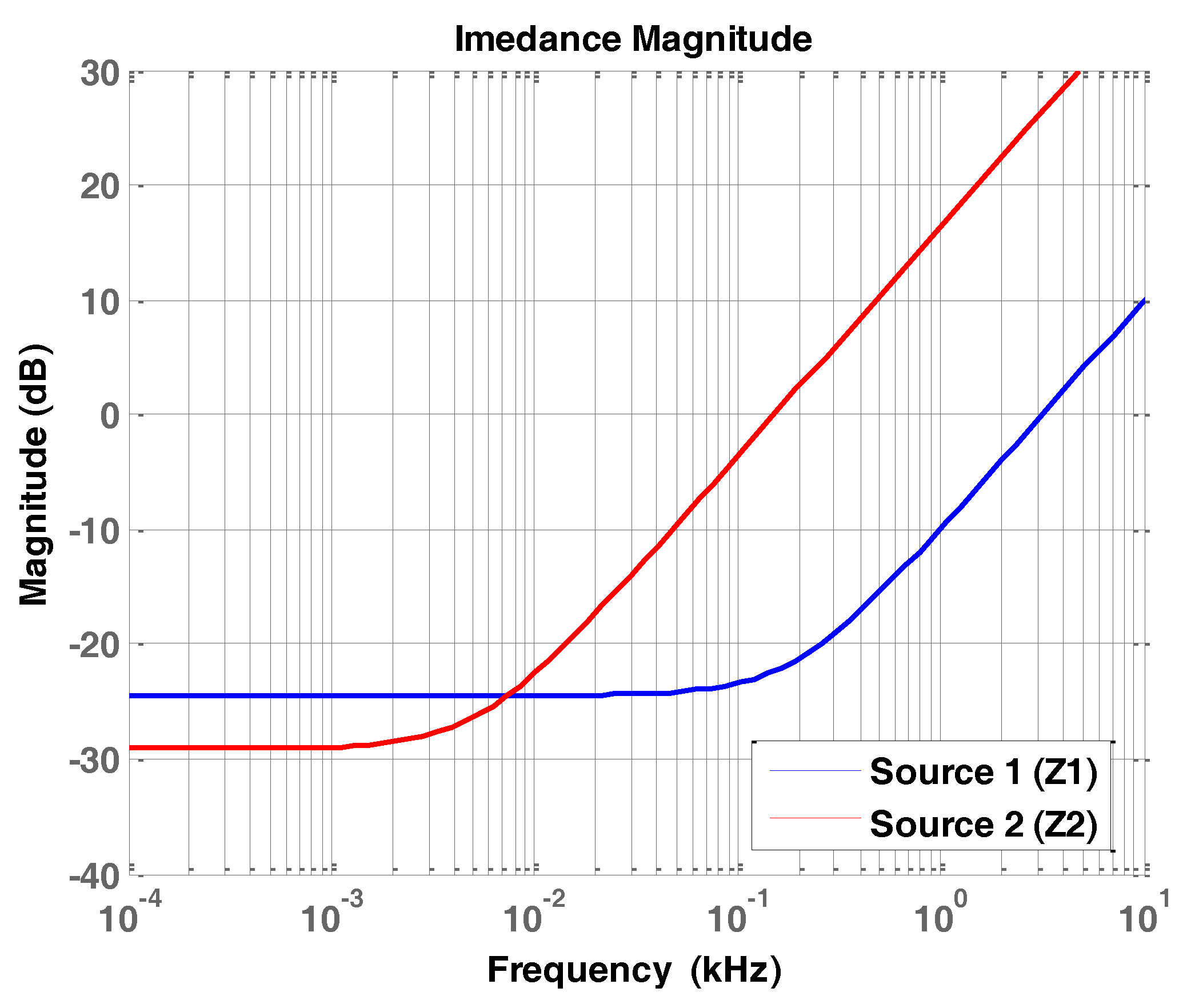
3.3. Virtual Inductance Based Power Management
3.4. Effectivenss of the Proposed Approach for MEA Applications
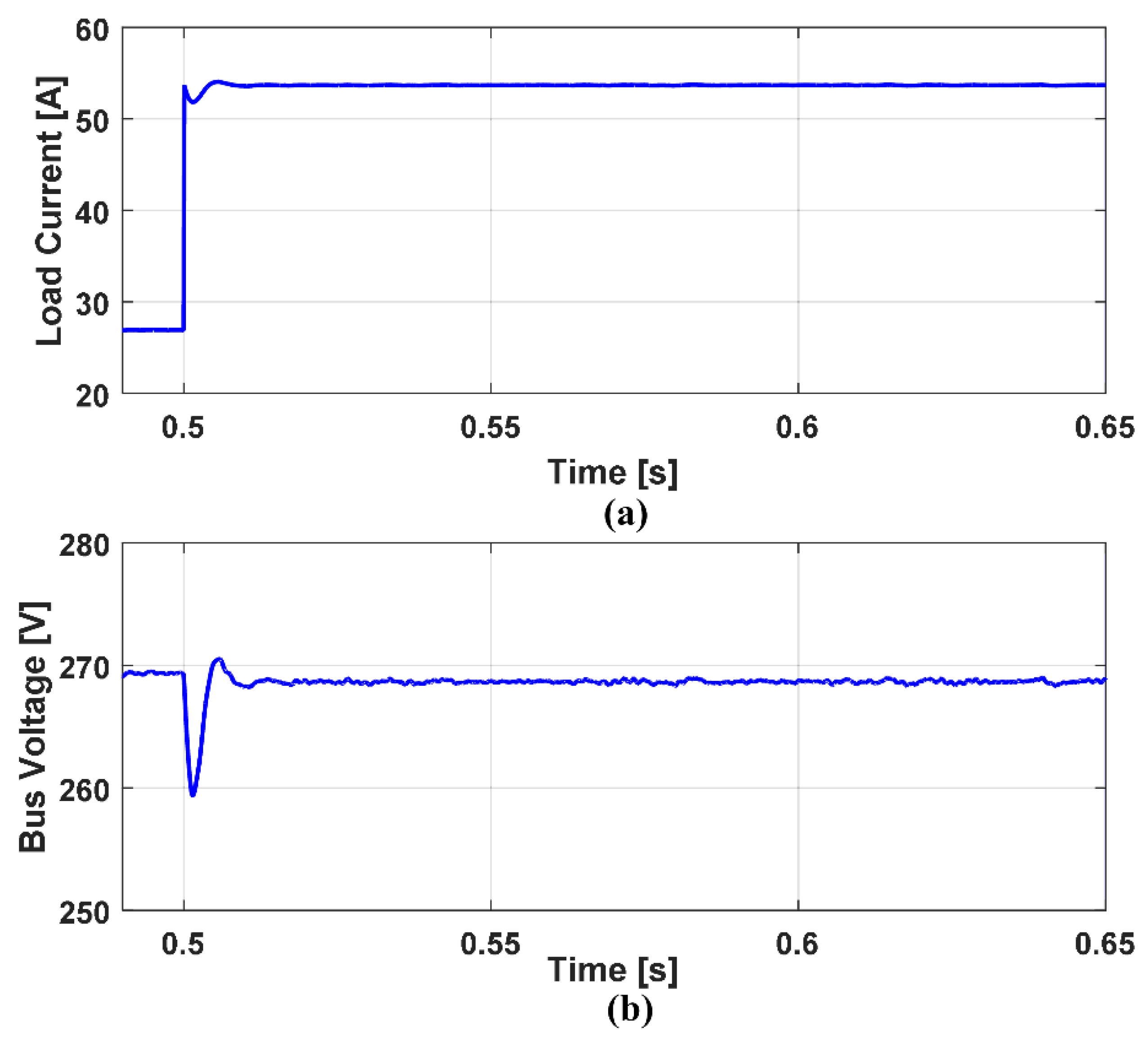
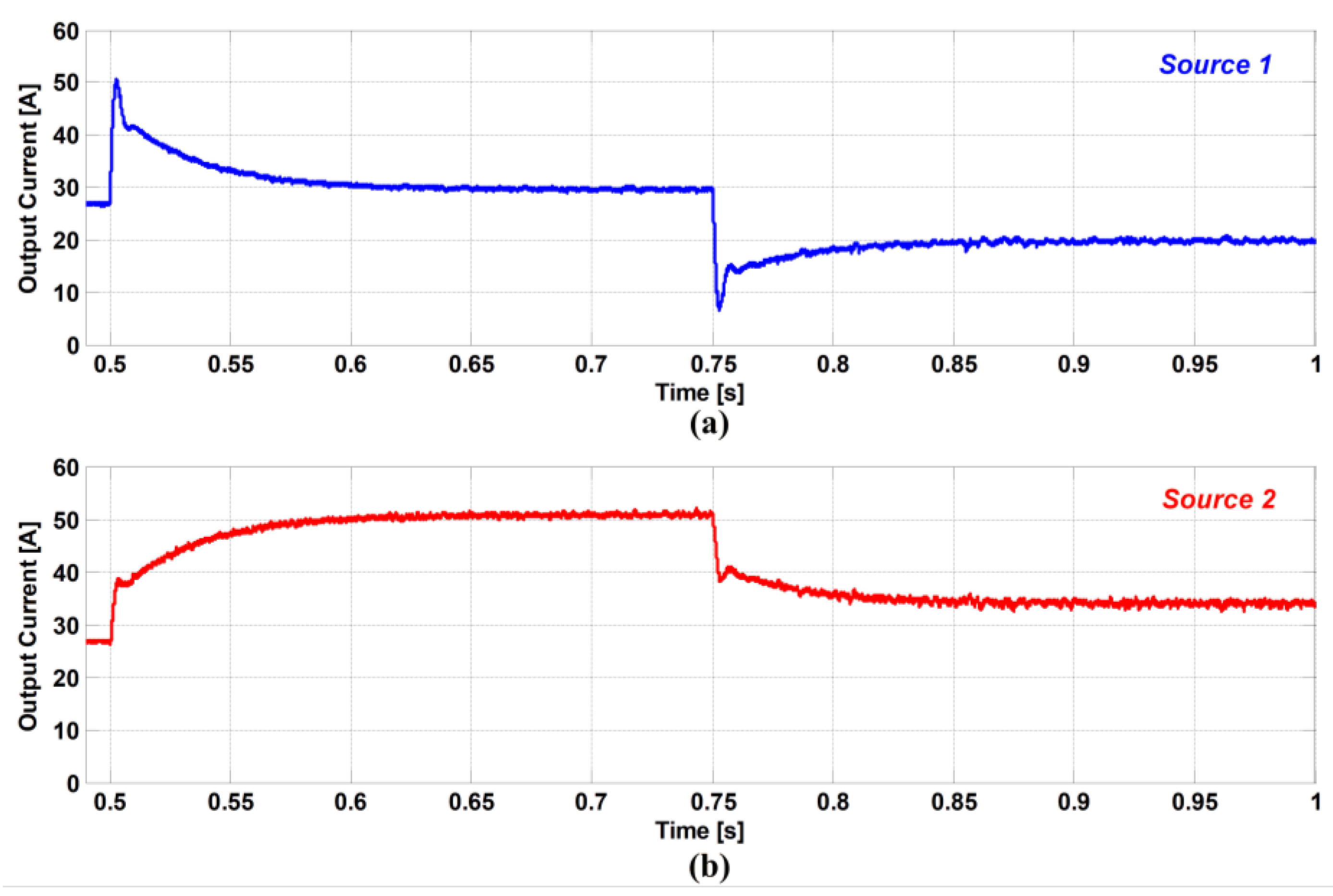
4. Verification Results
5. Conclusions
Author Contributions
Funding
Conflicts of Interest
Nomenclature
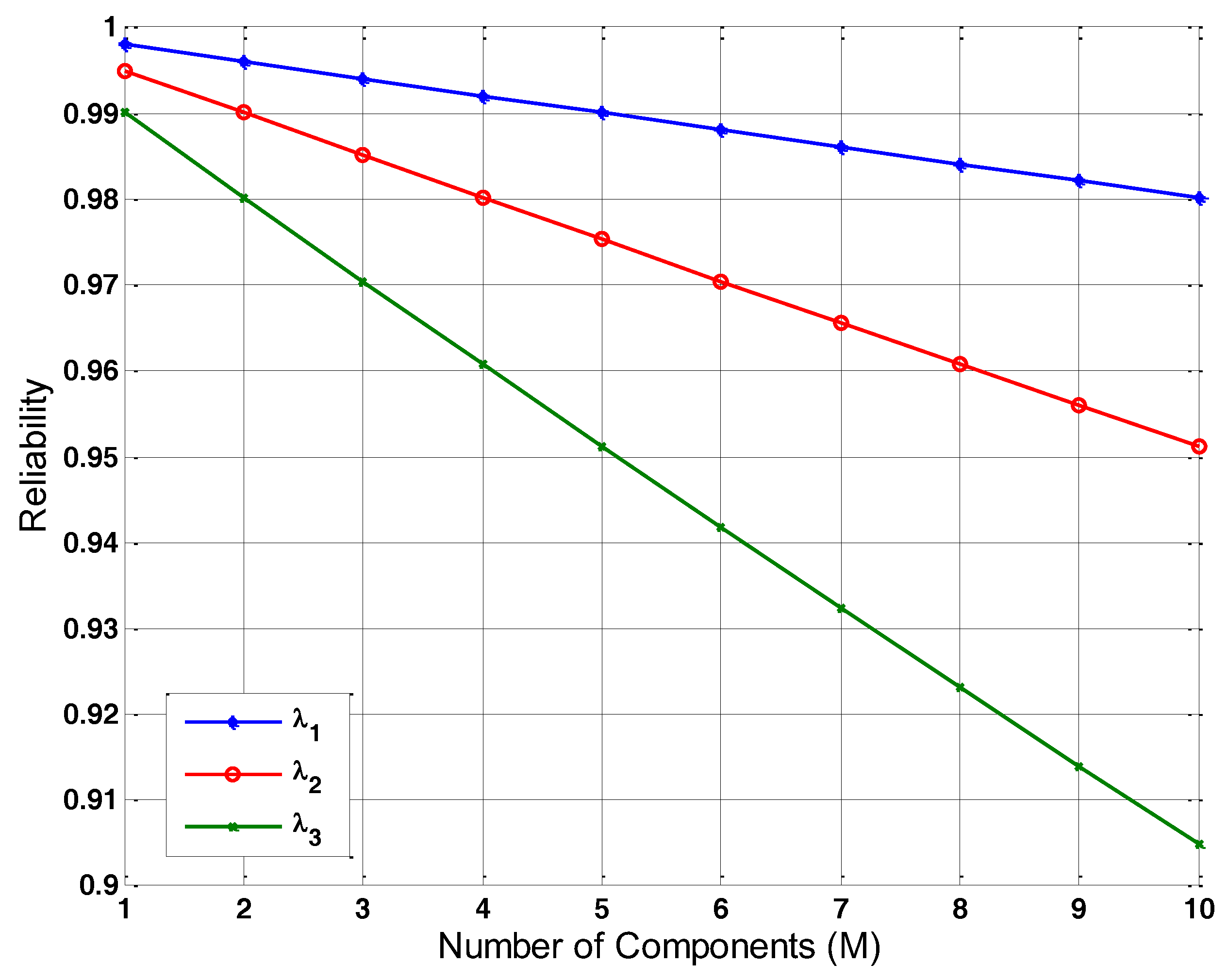
| M | Total number of EPS components |
| REPS | Reliability of the overall EPS |
| Ri | Reliability of the communication link between the PCU and the ith EPS component |
| λ | Failure rate of the communication link |
| Vok; iok | No-load voltage of the kth power source ; Output current of the kth power source |
| Zvk; Rvk; Lvk | Virtual impedance; Virtual resistance; Virtual inductance of the kth power source |
| Iload | Total load current |
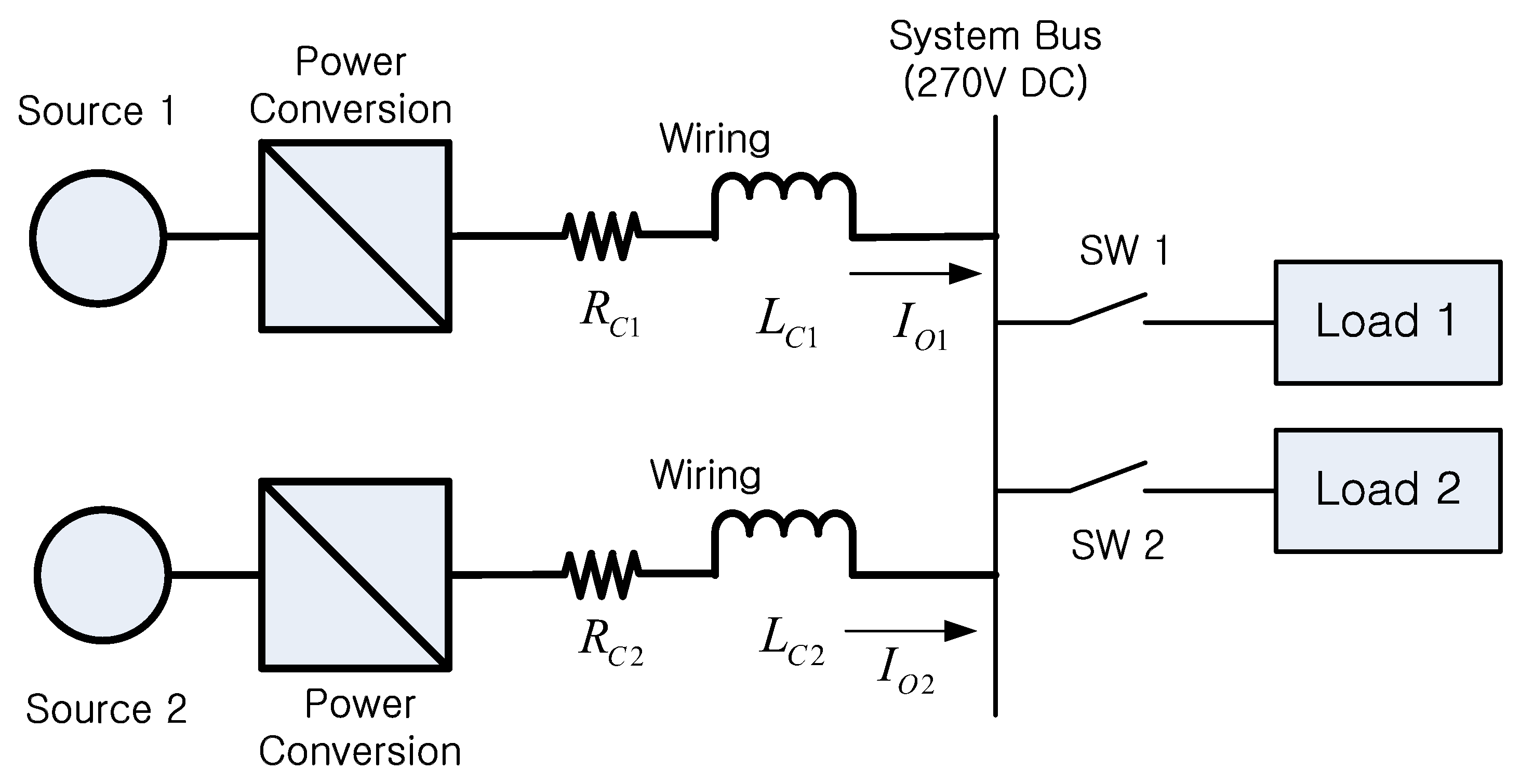
| Zck; Rck; Lck | Cable impedance; Cable resistance; Cable inductance of the kth power source |
| RL | Load resistance |
| Vk* | Voltage command of the kth power source |
| Mk | Transfer function between the load current and output current the kth power source |
| EPS | Electrical Power System |
| EMI | Electromagnetic Interference |
| MEA | More Electric Aircraft |
| PCU | Power Control Unit |
| PEMFC | Proton Exchange Membrane Fuel Cell |
| PV | Photovoltaics |
| PWM | Pulse Width Modulation |
| SOC | State-of-Charge |
| SOFC | Solid Oxide Fuel Cell |
References
- Un-Noor, F.; Padmanaban, S.; Mihet-Popa, L.; Mollah, M.N.; Hossain, E. A comprehensive study of key electric vehicle (EV) components, technologies, challenges, impacts, and future direction of development. Energies 2017, 10, 1217. [Google Scholar] [CrossRef]
- Jin, Z.; Meng, L.; Guerrero, J.M.; Han, R. Hierarchical control design for a shipboard power system with DC distribution and energy storage aboard future more-electric ships. IEEE Trans. Ind. Inform. 2018, 14, 703–714. [Google Scholar] [CrossRef]
- Sarlioglu, B.; Morris, C.T. More electric aircraft: Review, challenges, and opportunities for commercial transport aircraft. IEEE Trans. Transp. Electrif. 2015, 1, 54–64. [Google Scholar] [CrossRef]
- Ganev, E. Selecting the best electric machines for electrical power-generation systems: High-performance solutions for aerospace more electric architectures. IEEE Electrif. Mag. 2014, 2, 13–22. [Google Scholar] [CrossRef]
- Bennet, J.W.; Mecrow, B.C.; Atkinson, D.J.; Atkinson, G.J. Safety-critical design of electromechanical actuation systems in commercial aircraft. IET Electr. Power Appl. 2011, 5, 37–47. [Google Scholar] [CrossRef]
- Neuman, T. Fly the electrics skies. IEEE Spectr. 2016, 53, 44–48. [Google Scholar] [CrossRef]
- Gong, A.; Verstraete, D. Fuel cell propulsion in small fixed-wing unmanned aerial vehicles: Current status and research needs. Int. J. Hydrogen Energy 2017, 42, 21311–21333. [Google Scholar] [CrossRef]
- Moir, I.; Seabridge, A. Aircraft Systems: Mechanical, Electrical, and Avionics Subsystems Integration, 3rd ed.; Wiley: New York, NY, USA, 2008. [Google Scholar]
- Chen, J.; Wang, C.; Chen, J. Investigation on the selection of electric power system architecture for future more electric aircraft. IEEE Trans. Transp. Electrif. 2018, 4, 563–576. [Google Scholar] [CrossRef]
- Chang, J.; Wang, A. New VF-power system architecture and evaluation for future aircraft. IEEE Trans. Aerosp. Electron. Syst. 2006, 42, 527–539. [Google Scholar] [CrossRef]
- Areerak, K.N.; Bozhko, S.V.; Asher, G.M.; De Lillo, L.; Thomas, D.W.P. Stability study for a hybrid AC-DC more-electric aircraft power system. IEEE Trans. Aerosp. Electron. Syst. 2012, 48, 329–347. [Google Scholar] [CrossRef]
- Roboam, X.; Sareni, B.; Andrade, A. More electricity in the air: Toward optimized electrical networks embedded in more-electrical aircraft. IEEE Ind. Electron. Mag. 2012, 6, 6–17. [Google Scholar] [CrossRef]
- Wang, C.; Li, X.; Guo, L.; Li, Y.W. A nonlinear-disturbance-observer-based DC-bus voltage control for a hybrid AC/DC microgrid. IEEE Trans. Power Electron. 2014, 29, 6162–6177. [Google Scholar] [CrossRef]
- Dragicevic, T.; Guerrero, J.M.; Vasquez, J.C.; Skrlec, D. Supervisory control of an adaptive-droop regulated DC microgrid with battery management capability. IEEE Trans. Power Electron. 2014, 29, 695–706. [Google Scholar] [CrossRef]
- Dragicevic, T.; Lu, X.; Vasquez, J.C.; Guerrero, J.M. DC microgrids-Part 1: A review of control strategies and stabilization techniques. IEEE Trans. Power Electron. 2016, 31, 4876–4891. [Google Scholar] [CrossRef]
- Tahim, A.P.N.; Pagano, D.J.; Lenz, E.; Stramosk, V. Modeling and stability analysis of islanded DC microgrids under droop control. IEEE Trans. Power Electron. 2015, 30, 4597–4607. [Google Scholar] [CrossRef]
- Gu, Y.; Li, W.; He, X. Frequency-coordinating virtual impedance for autonomous power management of DC microgrid. IEEE Trans. Power Electron. 2015, 30, 2328–2337. [Google Scholar] [CrossRef]
- Xu, Q.; Hu, X.; Wang, P.; Xiao, J.; Tu, P.; Wen, C.; Lee, M.Y. A decentralized dynamic power sharing strategy for hybrid energy storage system in autonomous DC microgrid. IEEE Trans. Ind. Electron. 2017, 64, 5930–5941. [Google Scholar] [CrossRef]
- Zhao, X.; Li, Y.W.; Tian, H.; Wu, X. Energy management strategy of multiple supercapacitors in a DC microgrid using adaptive virtual impedance. IEEE J. Emerg. Sel. Top. Power Electron. 2016, 4, 1174–1185. [Google Scholar] [CrossRef]
- Ou, T.; Li, K.; Huang, C. Improvement of transient stability in a hybrid power multi-system using a designed NIDC (Novel Intelligent Damping Controller). Energies 2017, 10, 488. [Google Scholar] [CrossRef]
- Ou, T.; Hong, C. Dynamic operation and control of microgrid hybrid power systems. Energy 2014, 66, 314–323. [Google Scholar] [CrossRef]
- Motapon, S.N.; Dessaint, L.A.; Al-Haddad, K. A comprehensive study of energy management schemes for a fuel-cell hybrid emergency power system of more-electric aircraft. IEEE Trans. Ind. Electron. 2014, 61, 1320–1334. [Google Scholar] [CrossRef]
- Zhang, F.; Mollet, F.; Saudemont, C.; Robyns, B. Experimental validation of energy storage system management strategies for a local DC distribution system of more electric aircraft. IEEE Trans. Ind. Electron. 2010, 57, 3905–3916. [Google Scholar] [CrossRef]
- Lee, B.; Kwon, S.; Park, P.; Kim, K. Active power management system for an unmanned aerial vehicle powered by solar cells, a fuel cell, and batteries. IEEE Trans. Aerosp. Electron. Syst. 2014, 50, 3167–3177. [Google Scholar] [CrossRef]
- Ou, T. A novel unsymmetrical fault analysis for microgrid distribution systems. Electr. Power Energy Syst. 2012, 43, 1017–1024. [Google Scholar] [CrossRef]
- Ou, T. Ground fault current analysis with a direct building algorithm for microgrid distribution. Electr. Power Energy Syst. 2013, 53, 867–875. [Google Scholar] [CrossRef]
- Kwasinski, A.; Onwuchekwa, C.N. Dynamic behavior and stabilization of DC microgrids with instantaneous constant-power loads. IEEE Trans. Power Electron. 2011, 26, 822–834. [Google Scholar] [CrossRef]
- Lim, J.; Kim, H.; Cho, K.; Bae, J. Stand-alone microgrid inverter controller design for nonlinear, unbalanced load with output transformer. Electronics 2018, 7, 55. [Google Scholar] [CrossRef]
- Lei, T.; Wu, C.; Liu, X. Multi-objective optimization control for the aerospace dual-active bridge power converter. Energies 2018, 11, 1168. [Google Scholar] [CrossRef]
- Onambele, C.; Elsied, M.; Mpanda Mabwe, A.; El Hajjaji, A. Multi-phase modular drive system: A case study in electrical aircraft applications. Energies 2018, 11, 5. [Google Scholar] [CrossRef]
- Burgos, R.; Chen, G.; Wang, F.; Boroyevich, D.; Odendaal, W.G.; Van Wyk, J.D. Reliability-oriented design of three-phase converters for aircraft applications. IEEE Trans. Aerosp. Electron. Syst. 2012, 48, 1249–1263. [Google Scholar] [CrossRef]
- Muller, J.-K.; Mertens, A. Power electronics design for a direct-driven turbo compressor used as advanced high-lift system in future aircraft. In Proceedings of the 43rd Annual Conference of the IEEE Industrial Electronics Society, Beijing, China, 29 October–1 November 2017; pp. 1–6. [Google Scholar]
- Zhai, L.; Zhang, T.; Cao, Y.; Yang, S.; Kavuma, S.; Feng, H. Conducted EMI prediction and mitigation strategy based on transfer function for a high-low voltage DC-DC converter in electric vehicle. Energies 2018, 11, 1028. [Google Scholar] [CrossRef]
- Giglia, G.; Ala, G.; Piazza, M.C.D.; Giaconia, G.C.; Luna, M.; Vitale, G.; Zanchetta, P. Automatic EMI filter design for power electronic converters oriented to high power density. Electronics 2018, 7, 9. [Google Scholar] [CrossRef]
- Henke, M.; Narjes, G.; Hoffmann, J.; Wohlers, C.; Urbanek, S.; Heister, C.; Steinbrink, J.; Canders, W.R.; Ponick, B. Challenges and opportunities of very light high-performance electric drives for aviation. Energies 2018, 11, 344. [Google Scholar] [CrossRef]
- Diaz, N.L.; Luna, A.C.; Vasquez, J.C.; Guerrero, J.M. Centralized control architecture for coordination of distributed renewable generation and energy storage in islanded AC microgrids. IEEE Trans. Power Electron. 2017, 32, 5202–5213. [Google Scholar] [CrossRef] [Green Version]
- Gao, F.; Bozhko, S.; Costabeber, A.; Asher, G.; Wheeler, P. Control design and voltage stability analysis of a droop-controlled electrical power system for more electric aircraft. IEEE Trans. Ind. Electron. 2017, 64, 9271–9281. [Google Scholar] [CrossRef]
- Kim, M.; Kwasinski, A. Decentralized hierarchical control of active power distribution nodes. IEEE Trans. Energy Convers. 2014, 24, 934–943. [Google Scholar] [CrossRef]
- Guerrero, J.M.; Vasquez, J.C.; Matas, J.; de Vicuna, L.G.; Castilla, M. Hierarchical control of droop-controlled AC and DC microgrids-A general approach toward standardization. IEEE Trans. Ind. Electron. 2011, 58, 158–172. [Google Scholar] [CrossRef]
- Aten, M.; Towers, G.; Whitley, C.; Wheeler, P.; Clare, J.; Bradley, K. Reliability comparison of matrix and other converter topologies. IEEE Trans. Aerosp. Electron. Syst. 2006, 42, 867–875. [Google Scholar] [CrossRef]
- Gao, F.; Bozhko, S.; Asher, G.; Wheeler, P.; Patel, C. An improved voltage compensation approach in a droop-controlled DC power system for the more electric aircraft. IEEE Trans. Power Electron. 2016, 31, 7369–7383. [Google Scholar] [CrossRef]
- Yassine, M.; Fabris, D. Performance of commercially available supercapacitors. Energies 2017, 10, 1340. [Google Scholar] [CrossRef]
- Jayasinghe, S.G.; Meegahapola, L.; Fernando, N.; Jin, Z.; Guerrero, J.M. Review of ship microgrids: System architectures, storage technologies and power quality aspects. Inventions 2017, 2, 4. [Google Scholar] [CrossRef]
- Gonzalez-Espasandin, O.; Leo, T.J.; Navarro-Arevalo, E. Fuel cells: A real option for unmanned aerial vehicles propulsion. Sci. World J. 2014, 2014, 497642. [Google Scholar] [CrossRef] [PubMed]
- Gao, L.; Liu, Y.; Ren, H.; Guerrero, J.M. A DC microgrid coordinated control strategy based on integrator current-sharing. Energies 2017, 10, 1116. [Google Scholar] [CrossRef]
- Liu, Y.; Wang, J.; Li, N.; Fu, Y.; Ji, Y. Enhanced load power sharing accuracy in droop-controlled DC microgrids with both mesh and radial configurations. Energies 2015, 8, 3591–3605. [Google Scholar] [CrossRef]
- Hamzeh, M.; Ghafouri, M.; Karimi, H.; Sheshyekani, K.; Guerrero, J.M. Power oscillations damping in DC microgrids. IEEE Trans. Energy Convers. 2016, 31, 970–980. [Google Scholar] [CrossRef]
- Fletcher, T.; Thring, R.; Watkinson, M. An energy management strategy to concurrently optimize fuel consumption & PEM fuel cell lifetime in a hybrid vehicle. Int. J. Hydrogen Energy 2016, 41, 21503–21515. [Google Scholar]
- Bolborici, V.; Dawson, F.P.; Lian, K.K. Hybrid energy storage systems: Connecting batteries in parallel with ultracapacitors for high higher power density. IEEE Ind. Appl. Mag. 2014, 20, 31–40. [Google Scholar] [CrossRef]
- Rausand, R.; Holyland, A. System Reliability Theory: Models, Statistical Methods, and Applications, 2nd ed.; Wiley-Interscience: Hoboken, NJ, USA, 2004. [Google Scholar]
- Erickson, R.W.; Maksimovic, D. Fundamentals of Power Electronics, 2nd ed.; Springer: New York, NY, USA, 2001. [Google Scholar]
- Augustine, S.; Lakshminarasamma, N.; Mishra, M.K. Control of photovoltaic-based low-voltage DC microgrid system for power sharing with modified droop algorithm. IET Power Electron. 2016, 9, 1132–1143. [Google Scholar] [CrossRef]
- Lu, X.; Guerrero, J.M.; Sun, K.; Vasquez, J.C. An improved droop control for DC microgrids based on low bandwidth communication with DC bus voltage restoration and enhanced current sharing accuracy. IEEE Trans. Power Electron. 2014, 29, 1800–1812. [Google Scholar] [CrossRef]
- Paquette, A.D.; Reno, M.J.; Harley, R.G.; Divan, D.M. Sharing transient loads: Causes of unequal transient load sharing in islanded microgrid operation. IEEE Ind. Appl. Mag. 2014, 20, 23–34. [Google Scholar] [CrossRef]
- Gadoura, I.; Grigore, V.; Hatonen, J.; Kyyra, J.; Vallittu, P.; Suntio, T. Stabilizing a telecom power supply feeding a constant power load. In Proceedings of the 20th International Telecommunications Energy Conference (INTELEC), San Francisco, CA, USA, 4–8 October 1998; pp. 243–248. [Google Scholar]
- Aircraft Electric Power Characteristics. Available online: http://u.dianyuan.com/upload/space/2012/04/06/1333690328-628697.pdf (accessed on 16 July 2018).


| System Parameter | Value |
|---|---|
| Converter Switching Frequency | 20 kHz |
| Converter Inductanace | 1 mH |
| Converter Capacitance | 1 mF |
| Source Output Voltage | 500 V |
| Cable Resistance | Rc = 10 mΩ |
| Cable Inductance | Lc = 50 μH |
© 2018 by the authors. Licensee MDPI, Basel, Switzerland. This article is an open access article distributed under the terms and conditions of the Creative Commons Attribution (CC BY) license (http://creativecommons.org/licenses/by/4.0/).
Share and Cite
Kim, M.; Lee, S.G.; Bae, S. Decentralized Power Management for Electrical Power Systems in More Electric Aircrafts. Electronics 2018, 7, 187. https://doi.org/10.3390/electronics7090187
Kim M, Lee SG, Bae S. Decentralized Power Management for Electrical Power Systems in More Electric Aircrafts. Electronics. 2018; 7(9):187. https://doi.org/10.3390/electronics7090187
Chicago/Turabian StyleKim, Myungchin, Sung Gu Lee, and Sungwoo Bae. 2018. "Decentralized Power Management for Electrical Power Systems in More Electric Aircrafts" Electronics 7, no. 9: 187. https://doi.org/10.3390/electronics7090187