Article

Simple Torque Control Method for Hybrid Stepper Motors Implemented in FPGA

Information Engineering Department (DINFO), University of Florence, 50139 Florence, Italy
*
Author to whom correspondence should be addressed.
Electronics 2018, 7(10), 242; https://doi.org/10.3390/electronics7100242
Submission received: 12 September 2018 / Revised: 30 September 2018 / Accepted: 4 October 2018 / Published: 7 October 2018
(This article belongs to the Section Microelectronics)

Abstract

:
Stepper motors are employed in a wide range of consumer and industrial applications. Their use is simple: a digital device generates pulse-bursts and a direction bit towards a power driver that produces the 2-phase currents feeding the motor windings. Despite its simplicity, this open-loop approach fails if the torque load exceeds the motor capacity, so the motor and driver should be oversized at the expense of efficiency and cost. Field-Oriented closed-loop Control (FOC) solves the problem, and the recent availability of low cost electronics devices like Digital Signal Processors, Field Programmable Gate Arrays (FPGA), or even Microcontrollers with dedicated peripherals, fostered the investigation and implementation of several variants of the FOC method. In this paper, a simple and economic FOC torque control method for hybrid stepper motors is presented. The load angle is corrected accordingly to the actual shaft position through pulse-bursts and direction commands issued towards a commercial stepper driver, which manages the 2-phase winding currents. Thanks to the FPGA implementation, the control loop updates the electrical position every 50 μs only, thus allowing a load angle accuracy of −1/100 rad for a rotor velocity up to 750 rev/min, as shown in the reported experiments.

1. Introduction

The stepper motor [1] is widely used nowadays in a large range of applications such as 3D printers, industrial manufacturing tools, robotic arms, etc. Part of its success is certainly due to its capability of moving in a sequence of accurate and discreet locations (steps). A microcontroller connected to one of the several power drivers available on the market through a “step” clock and a “direction” command is often sufficient for the motor control [2]: For every “step” pulse, the driver modifies the 2-phase currents that feed the motor so that the shaft rotates by a “step” (typically 1.8°) or a fraction of it (μ-step) [3].
Unfortunately, the performance of the stepper motor heavily depends on the load condition. Therefore, if the load accidentally increases over the motor capacity, the control misses the actual shaft position and the application fails. To prevent this catastrophic event, stepper motors (and their drivers) are typically selected with a torque capacity that abundantly exceeds the nominal requirement. This results in oversized motors, and waste of power and heat [4]. Closed-loop motor control with the Field Oriented Control (FOC) method [5,6] solves this problem. The typical FOC implementation is based on Direct-Quadrature (DQ) coordinate transformations [6,7] that, in the past, required a considerable calculation effort and correspondingly complex hardware, which was not compatible with economic consumer applications. In recent years, however, the availability of microcontrollers with dedicated peripherals and/or economic Field Programmable Gate Arrays (FPGAs) has supported the development and implementation of new closed-loop approaches. In particular, FPGA represents a standard device for industrial applications [8,9], including motor control. For example, a Proportional-Integral-Derivative (PID) controller [10] with velocity feed-forward was proposed in [11]; in [12] a closed-loop control system based on motor parameter identification was presented; in [13] and [14], motor controllers based on Neural Networks are proposed.
In this paper a closed-loop torque control method for hybrid stepper motors is presented with its FPGA implementation. The method is based on a simple control loop that, thanks to the FPGA’s performance, executes every few 10 s of μs. Every loop iteration, the motor shaft position is monitored through an incremental encoder, and the stator magnetic field position is updated so that the relative phase between the positions of the stator and the rotor generates the desired load angle. While this quick loop maintains accurate control of the load angle, the magnitude of the phase currents is adjusted to obtain the programmed torque.
The output of the control loop consists of the number of μ-steps and the direction bit the rotor should move to maintain the desired load angle. These data perfectly fit with the “step/direction” interface present in several commercial power devices which are typically employed for open-loop μ-step motor control. In other words, this method does not need custom power electronics for the generation and control of the motor phase currents, which can be delivered by one of the monolithic devices already available in the market.
The proposed control is implemented in a FPGA from the MAX10 family (Intel/Altera, San Jose, CA, USA), connected to the PowerStep01 stepper driver (STMicroelectronics, Geneva, Switzerland). The paper presents the basics of the applied method in the next section; the employed electronics system and the FPGA implementation are described in Section 3; finally, several experiments are reported in Section 4.

2. Methods

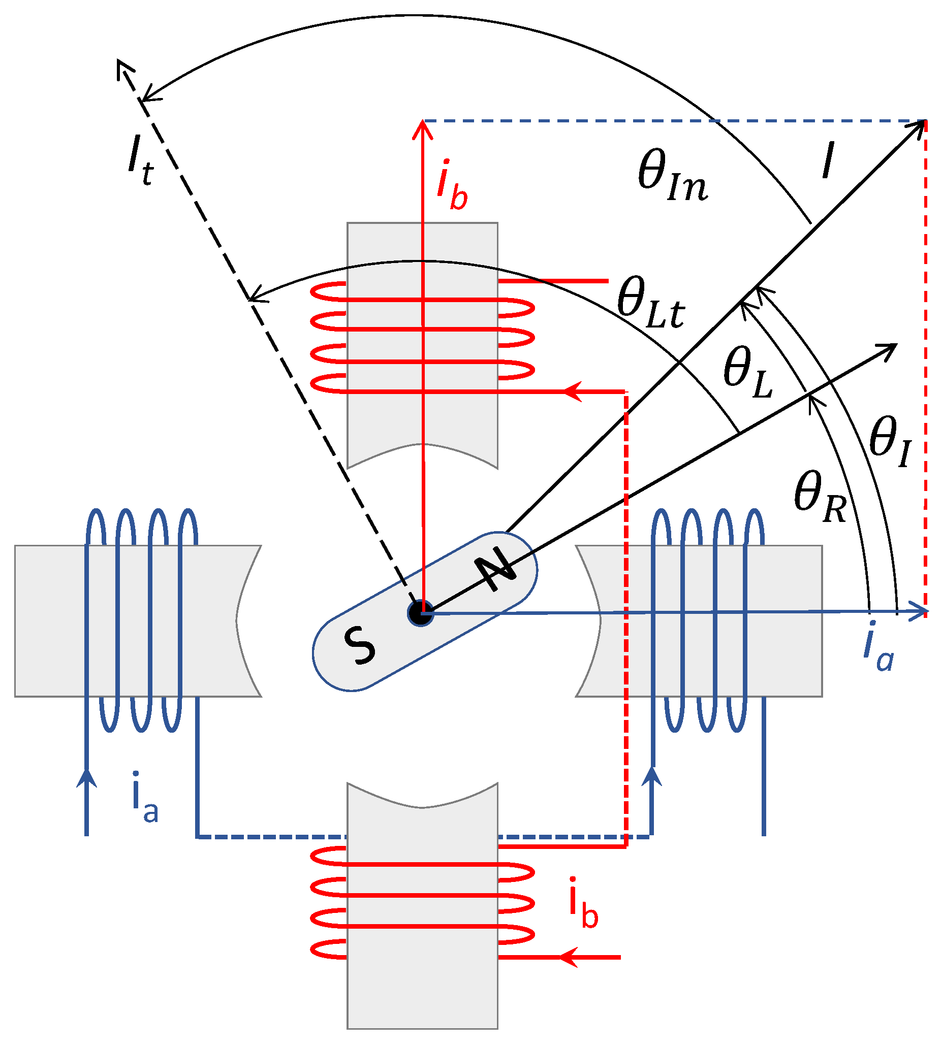
2.1. Torque Generation and Step Movement

In a hybrid 2-phase stepper motor, the torque is generated by the interaction of the field produced by the rotor fixed magnet, and the field dynamically generated by the stator windings. The torque is composed by 3 components: the cogging, the reluctance, and the electrodynamic component [15,16]; however, in this work, the electrodynamic component, being predominant, is the only one considered. With reference to Figure 1, if I a and I b are the currents flowing in the 2 windings, the magnitude and angle of the resulting current is I = I a 2 + I b 2 and θ I = tan 1 ( I b I a ) . The motor torque Γ E is generated by I combined to the load angle θ L , i.e., the phase angle between the rotor position θ R and the current position θ I [15]:
Γ E = K t · I · sin ( θ L ) = K t · I · sin ( θ R θ I )
where K t is the torque constant. The torque is null when θ L = 0 independently from the current magnitude, and it is maximum when θ L = π/2. A sinusoidal current excitation produces a continuous rotation of the current vector of amplitude I and a corresponding movement of the equilibrium position of the rotor. However, the typical commercial stepper driver produces only a limited set of quantized values of the phase currents. If N M is the number of the different current levels the driver produces, 4 N M equilibrium positions are generated around the electrical circle of Figure 1 in θ R = 0 , π 2 N M ,   2   π 2 N M ,   3   π 2 N M , ( 4 N M 1 ) π 2 N M [3].

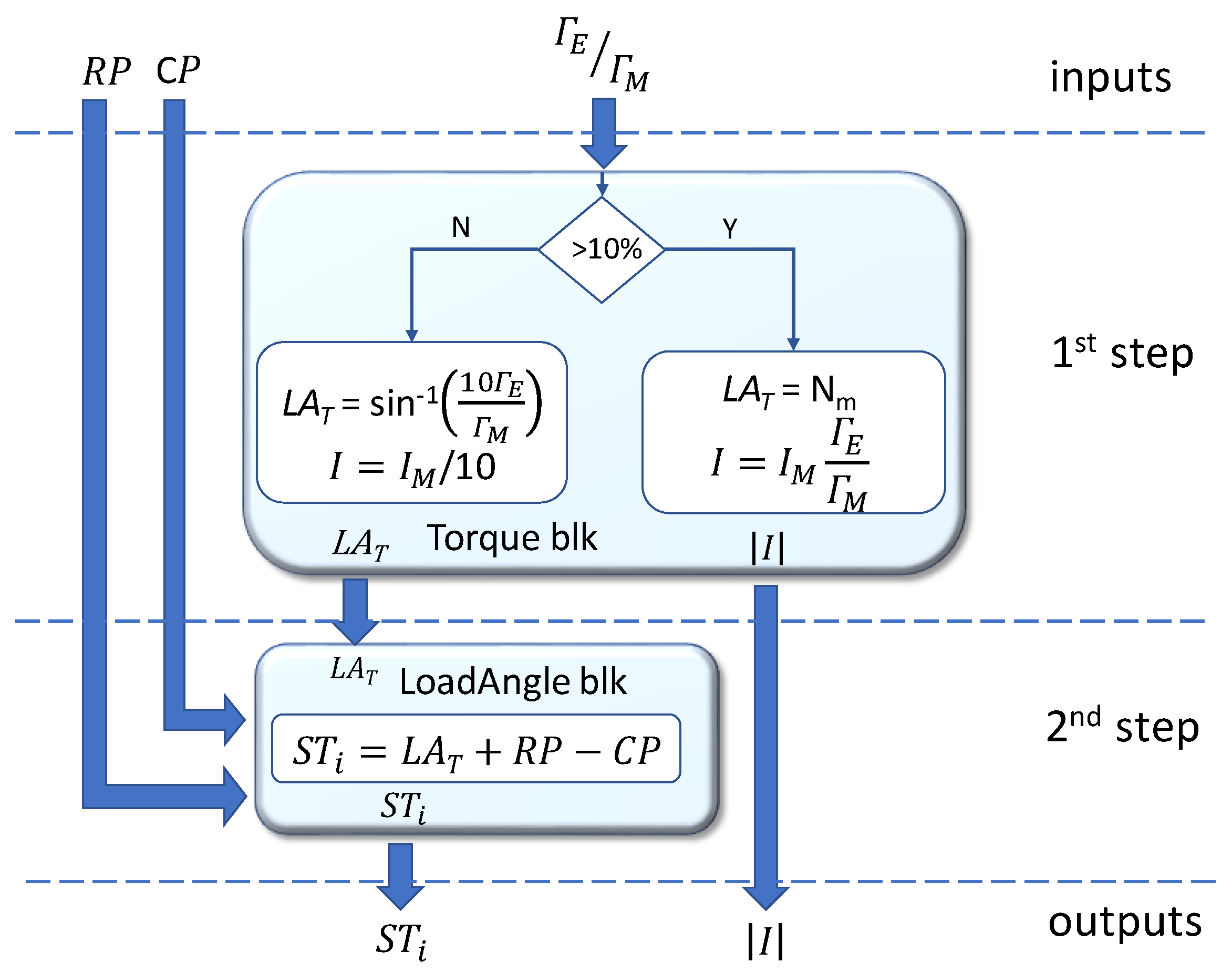
2.2. Torque Modulation

According to (1), the torque can be modulated by controlling the load angle, θ L , and/or the current, I . The typical FOC application regulates the motor windings currents to generate a load angle of θ L = ±π/2, and the current magnitude I modulates the torque. This is the most efficient approach, since the minimum current is used for a given torque. However, in some situations, maintaining I fixed and modulating the torque through θ L can be convenient. Let’s consider, for example, a 10 A motor driver that, at a particular moment, is required to produce a low torque of 1/100 of the nominal value. By controlling the load angle to 90°, the windings’ current magnitude should be reduced to 10/100 = 0.1 A. It is feasible that the driver, which typically employs chopper amplifiers designed for high currents, suffers reduced accuracy in this low current range [17]. Thus, imposing a current magnitude of, for example, I = 1 A, and reducing the load angle at sin ( θ L ) = 1 / 10 , can help to make the driver produce the desired torque while working in its preferred current range.
In order to show that the proposed method is able to modulate the torque by changing both I and θ L , in the proposed implementation we chose a double control approach, as summarized in Table 1. Which of the 2 control approaches is applied depends on the instantaneous required torque ratio Γ E / Γ M , where Γ M = K t · I M is the nominal torque of the motor, produced at the nominal current I M with the maximum load angle. For high torque values, i.e., Γ E / Γ M > 10% (see first row of Table 1), the same approach as in the FOC is used: the load angle is fixed to ±π/2, and, from (1), the torque is Γ E = ± K t I , which is modulated by controlling I (the sign depends on the direction of rotation). On the other hand, when a torque lower than Γ E / Γ M = 10% is required (bottom row in the table), the current is fixed to I = 0.1· I M . From (1), the torque is Γ E = K t I M 10 sin ( θ L ) , which is modulated by changing θ L .
The Torque column of Table 1 describes the achieved torque when the current magnitude and the load angle are known. To control the motor we need the opposite, i.e., given a desired torque Γ E , we need to know the load angle, θ L , and the current, I , which produce such a torque. This result is obtained by solving the torque equations present in the Torque column of Table 1 with respect to the current I and the angle θ L (first row and second row of Table 2):
Table 2 should be read as follow: given the desired torque Γ E , the load angle and current to be used with the the motor to generate such a torque are those reported in Angle and Current columns, at the row selected by the Condition column.
It is now convenient to distinguish the actual current I and load angle θ L , from the target current I t and load angle θ L t , respectively. With reference to Figure 1, the first are the values currently present in the motor, while the others are the values that the motor control should achieve for generating the imposed torque. According to the aforementioned strategy, the electronics control, during the rotor movement, should drive the 2-phase currents so that I has the desired amplitude ( I = I t ) and is dynamically positioned to maintain the target load angle ( θ L = θ L t ). Thus, if θ R and θ I are the actual rotor and current positions, (see Figure 1), the current position should be incremented/decremented by an angle of:
θ I n = θ L t θ L = θ L t + θ R θ I .
For practical reasons, since we are going to use a μ-step driver where the current position can be incremented/decremented in discrete steps of amplitude 2π/4/ N M rad, it is convenient to rewrite (4) as:
S T i = L A T + R P C P
where S T i , L A T , R P , C P , correspond to θ I n , θ L t , θ R , θ I , respectively, now expressed in μ-step unit.
For a better understanding of the proposed method, Figure 2 summarizes the control procedure. The instantaneous desired torque, expressed as torque ratio Γ E Γ M , the present current position, C P , and rotor position, R P , are inputs to the procedure. The calculation is divided into 2 steps. In the first step (Figure 2, top), the torque ratio is compared to the 0.1 threshold. If higher (Y-branch of the graph in Figure 2), the load angle is fixed to the maximum, i.e., θ L t = π 2 , corresponding to L A T = N M µ-steps, and the current magnitude is calculated according to (3a). On the other hand, if the torque ratio is lower than the threshold (N-branch of the graph in Figure 2), the current module is set to its minimum I t = 0.1 · I M , and the torque is modulated through the load angle, as calculated by (3b).
In the second step (Figure 2, bottom), the target load angle L A T and the actual current and rotor positions are used in (5) to obtain the number of μ-steps S T i necessary to update the C P position so that the load angle changes from θ L to the target load angle θ L t . The output values I t and S T i are finally sent to the motor drive. Please note that when the border value of Γ E = 0.1 · Γ M is used in both the branches of the procedure, it produces the same current module I t = 0.1 · I M and target load angle L A T = N M . This confirms that the decision above the threshold does not produce discontinuities in the generated currents and target angles.
The 2nd step of the descripted procedure represents the quick and simple control loop mentioned in Section 1. It should loop at a high rate, so that CP tracks RP accurately with the correct phase during the motion of the shaft, which can rotate at several rev/s. On the other hand, the 1st step is more relaxed, since the torque changes are affected by the relatively slow dynamics of the motor mechanics. For example, let us consider a motor running at a constant velocity of 1000 rpm and loaded by a constant resistant torque. In case of a 200-step/turn motor controlled with 16 μ-step per step, the shaft runs a μ-step every 20 μs. To maintain the load angle, the control loop should correct the CP position with comparable timing, while no change is made to I t and θ L t .

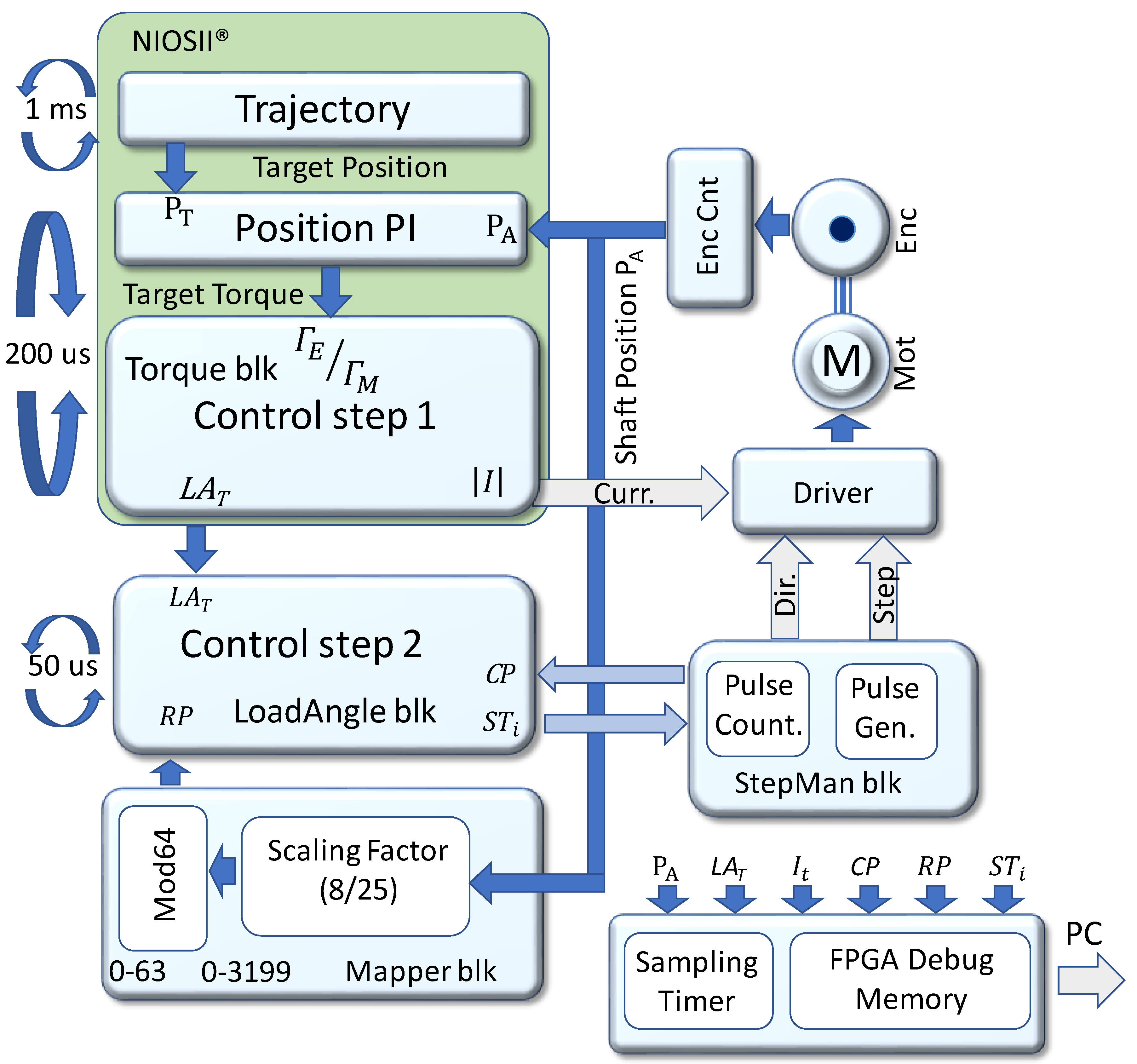
3. Method Implementation

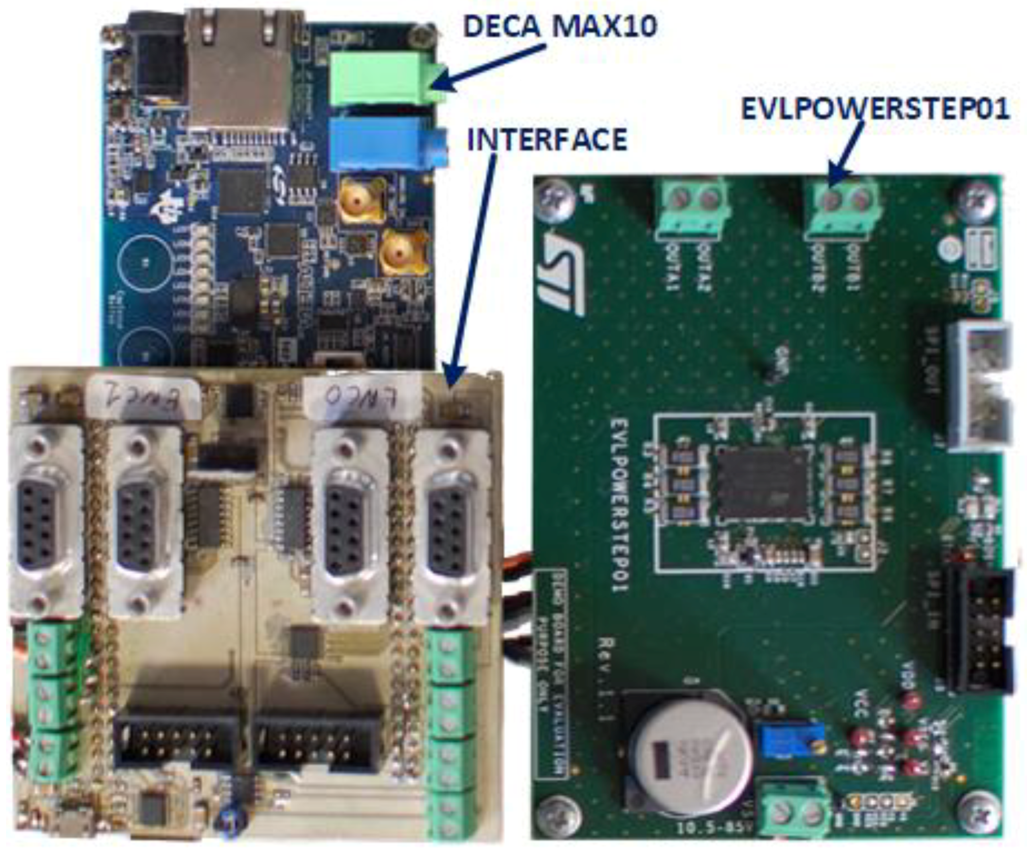
3.1. The Electronics

The proposed method was implemented in an electronics system based on 3 boards (see Figure 3). The DECA MAX10 (Arrow Electronics, Centennial, CO) includes an FPGA from the low-cost MAX10 family produced by Altera (San Jose, CA). It is connected to a homemade interface board that includes the basic electronics to read the quadrature signals from incremental encoders, and to connect to the evaluation boards of the PowerSTEP01 motor control device. The board and the device are both produced by STMicroelectronics (Geneva, Switzerland). PowerSTEP01 is able to drive a stepper motor with up to 80 V and 10 A currents in an open loop. In this work, the device was set for N M = 16 (1/16 μ-step mode), and used in “Step-clock” mode, where it rotates the current position, C P , by a single µ-step every rise-edge generated on the step-clock signal. The direction of the rotation and the current are set by specific commands sent through a SPI channel.

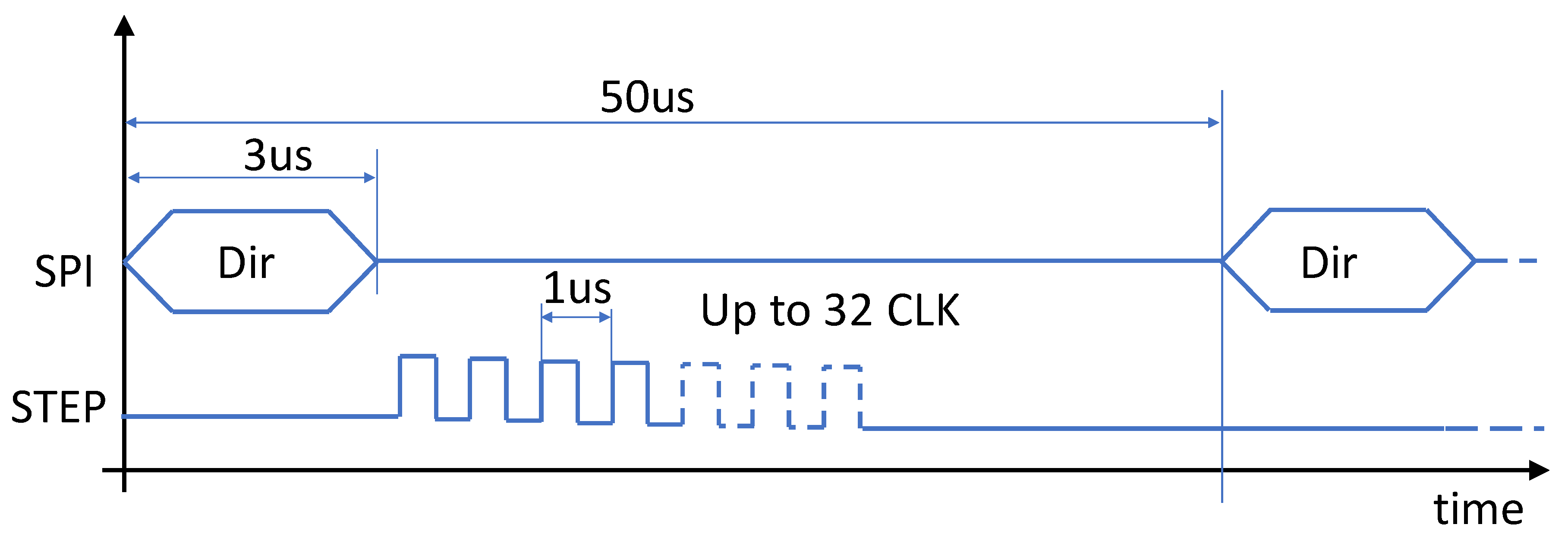
3.2. FPGA Implementation

The proposed method is implemented in the FPGA of the DECA MAX10 board, and is sketched in Figure 4. This implementation refers to a stepper driver set for N M = 16 and a 10 k pulse-per-turn encoder; however, it can easily be adapted to different settings. The time-critical calculations, like the control loop (5), are implemented in the FPGA fabric and coded directly in VHDL, while parts of the remaining tasks are coded in the C language and run in a NiosII® soft processor included in the FPGA. This approach allowed low execution time for the control loop (5) and a faster and easier code development for the other tasks. The sections coded in the soft-processor include a conventional Proportional-Integral (PI) controller [10] and a simple trajectory generator, which are ancillary blocks that are necessary to allow the experimental test of the torque control method.
With reference to Figure 4, the soft processor includes the simple trajectory loop, that according to a programmed trajectory, calculates the target position PT every 1 ms. PT feeds the PI controller [10] that compares PT to the actual position PA and outputs the target torque Γ E . The torque is then processed in the Torque block, which applies the first step of the control procedure detailed in Figure 2, and generates the required current I t and the target load angle L A T . L A T is delivered to the LoadAngle block, while I t is directly programmed to the driver through the SPI. Both the PI and the load angle calculation run every 200 μs.
The FPGA fabrics include several interacting blocks. The EncCnt counter (Figure 4 top, right) tracks the actual rotor position PA by integrating the quadrature signals produced by the encoder. PA is then used by the PI and the Mapper block in the FPGA fabric.
In the Mapper block, the physical position of the rotor PA is converted from encoder to μ-step units [18] (8/25 factor for 10 k pulse/turn encoder and N M = 16). The least-significant 5 bits of this value maps the rotor position in the electrical circle of Figure 1, RP, expressed in μ-step unit, which is delivered to the LoadAngle block.
The current position CP is tracked in the StepMan block (see Figure 4). The number of μ-steps S T i demanded to the driver in every control cycle are accumulated in the “step counter” with a sign that depends on the direction of rotation. The counter works with a 4 N M module: for N M = 16 a 5-bit counter is used.
The LoadAngle block (see Figure 4) finally calculates the μ-steps required to maintain the desired load angle, S T i , by applying the second step of the control procedure described in Figure 2 to the inputs provided from the blocks previously described. Every 50 µs, S T i is delivered to the StepMan block that issues to the powerSTEP01 driver the direction command followed by a burst of S T i electrical pulses of 1 µs each.

3.3. Debug Memory

The FPGA includes a debug memory (see Figure 4 bottom, right), where PA, L A T , I t , CP, RP, and S T i parameters are simultaneously saved with a sampling rate set by the user from 1 μs to 100 ms. Up to 4096 values of each parameter can be saved without interfering with the algorithm. The memory can be downloaded to a host PC when the motor is stopped. Although this feature has no impact on the algorithm, it is essential for debugging and performance analysis.

3.4. Timings and Resources

The trajectory controller updates the target position, PT, every 1 ms, and executes in 1.0 μs on a Nios processor clocked at 100 MHz. The PI controller and the torque control run every 200 μs, and execute the calculations in 1.5 μs only. This result is obtained using a look-up table for the sin inversion necessary in control step 1 (see Table 2, second row) for low torque condition. The remaining tasks, performed in FPGA fabric, are simple mathematical calculations or logic operations that take a few clock cycles at most to execute. The LoadAngle block (step 2 in Figure 2) is evaluated every 50 μs. In this period, the StepMan block issues a SPI command and a step-clock burst to the driver (see Figure 5). The SPI transmission, 1 byte at 4 MHz, takes about 3 μs. PowerSTEP01 driver requires a step-clock period of 1 μs, so the maximum length of the burst is of 32 μs (every position in a 64 μ-steps electrical circle can be reached by, at maximum, 32 μ-steps towards the shorter path). The minimum temporal length of a torque control loop is thus 3 + 32 = 35 μs, which fits well in the 50 μs period used here.
The resources employed in the FPGA are reported in Table 3. As expected, most of the resources are used by the Nios® soft processor, while the other control blocks need relatively few logic cells and registers, and no memory nor mathematical processors (DSPs).

4. Experiments

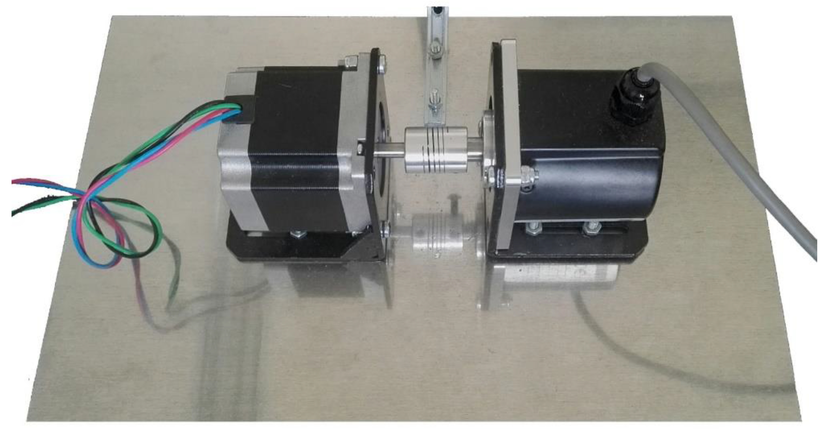
4.1. Experimental Set-Ups

The control method was implemented in the electronics system reported in Section 3.1, which was connected to the set-ups shown in Figure 6. The set-up is composed by the M1233041 stepper motor (Lam Technologies, Florence, Italy) connected to the REV621 (Elap, Milan, Italy) encoder through a flexible mechanical coupling. Table 4 reports the main features of the employed motor and encoder.

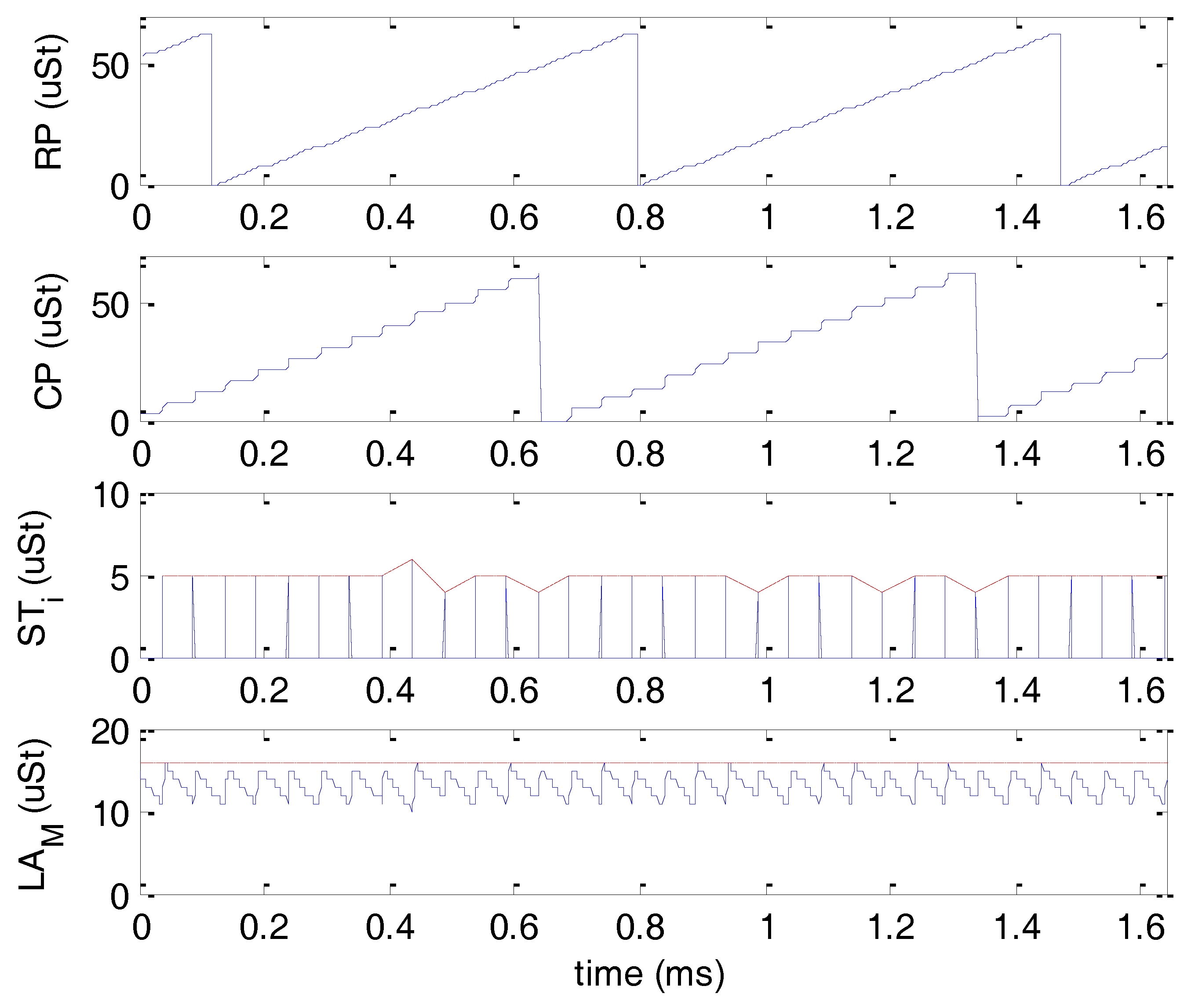
4.2. Control Procedure Test

In this test, the trajectory and PI control loops implemented in the Nios II® were bypassed. The soft processor was programmed to set a fixed torque ratio Γ E Γ M = 0.5. Being the ratio higher than the 0.1 threshold, the control sets a fixed current I t = 0.5 · I M = 2.1 A and a 90° load angle, i.e., L A T = N M = 16 µ-steps. The debug memory in FPGA was programmed to acquire a complete set of parameters every 1 µs. The motor was enabled for 1 s, and when the rotor reached a stable velocity after the initial acceleration, the debug memory was downloaded and processed in Matlab (The Mathworks, Natick, MA, USA). The parameters trend is reported in Figure 7 for a period of about 1.6 ms. The rotor electrical position (RP, Figure 7 first row) completes an electrical revolution (i.e., 64 μ-steps) in 0.68 ms. An electrical revolution corresponds to 4 steps [3]; thus, since the employed motor features 200 step/rev, the shaft performs a complete physical turn in 200/4∙0.68 = 34 ms. The current electrical position, CP, is reported in the 2nd row of Figure 7. As expected, it has a step-like behavior, with each step being 50 μs, i.e., the loop period. Similarly to RP, CP performs an electrical revolution (0–64 μ-steps) in 34 ms.
Every 50 μs, the controller calculates S T i from RP and CP (see 3rd row of Figure 7). In this experiment, S T i is in the range 5 ± 1 μ-steps, but most of the time is exactly 5 μ-steps. The calculated value is then used to update CP in next control period. The measured load angle, calculated in Matlab® as L A M = CP RP (see Figure 1) is reported in the last row of Figure 7, where it is compared to the target angle L A T represented by the horizontal dashed line at 16 μ-step. It features a rough triangular shape of 50 μs period. When the CP is updated by S T i μ-steps, L A M reaches L A T and the load angle error is zero. Then, in the following 50 μs, the shaft moves, RP rises, and L A M diminishes until the next control period zeroes the error again.
This experiment helps to clarify that the error between the measured and target angle depends on the motor velocity and the control period T . In fact, the higher the velocity, the wider the angle turned by RP in the control period. Quantitatively, the load angle peak error, in μ-steps can be expressed as:
Lerr = ω 2 π · 3200 · T
where ω is the motor velocity in rad/s and 3200 is the number of μ-steps per revolution. Since the error features a triangle-like shape (see last row of Figure 7), its mean value is half of the peak, i.e., Lerr/2.

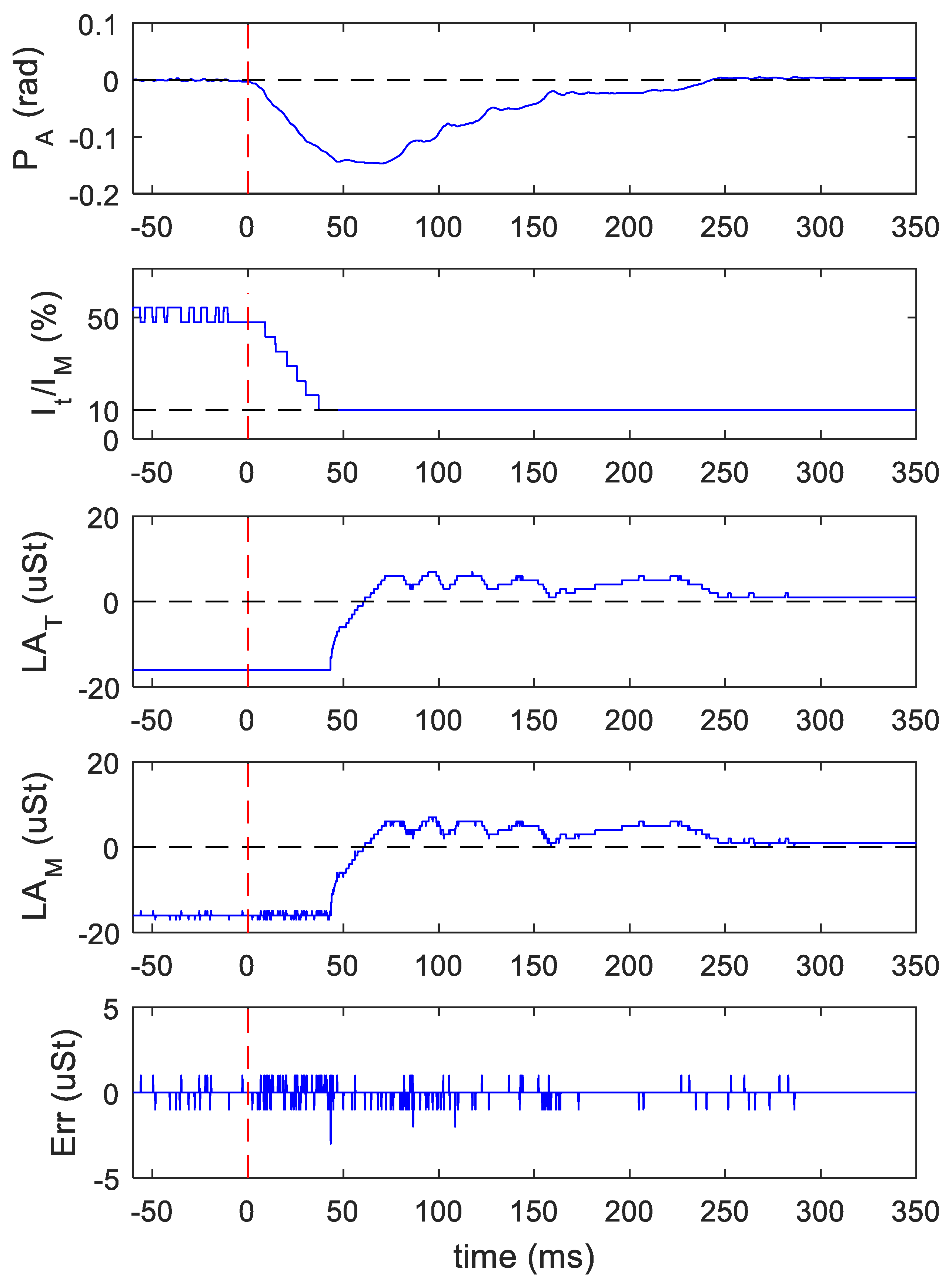
4.3. Torque Load Disturbance Test

With the set-up used in previous experiment, the trajectory generator was disabled and the PI was enabled with its input fixed to PT = 0 (see Figure 4). The debug memory was programmed to save a parameter set every 200 μs. In this test, the motor shaft was loaded with an external positive torque, which was released at time t = 0. Figure 8 reports the shaft position measured by the encoder, PA, the current ratio, It/IM, the target angle, L A T , calculated by the motor control, and the measured load angle, L A M , together with its error with respect to the target angle.
Before the torque was released (t < 0), the control system maintained the rotor at position PA = 0 by imposing the maximum load angle L A T = −16 μ-steps and a current of about 50% of the nominal value. After the external torque was released (t > 0), the control system reacted by reducing the current to its minimum of 10% in about 40 ms, then further reduced the torque by lowering the load angle towards 0. Meanwhile, due to the sudden load change, the shaft rotated of about −1.5 rad out of position, so the PI responded by imposing a slight positive load angle (t > 60 ms), while maintaining the current at its minimum level. The shaft recovered the target position in about 250 ms and the load angle decreased to 0. The error between the target and measured load angles, shown in last row, is within ±1 μ-step, except for few outliers. The load angle error is the same with (t < 0), and without (t > 0) the presence of load. The position error calculated as mean ± standard deviation of the errors measured before torque release (t < 0) is 0.05 ± 1.3 mrad, while after a stable condition was reached at t > 250 ms, is 0.09 ± 1.4 mrad. The test shows that the control reacts to a strong load change recovering the original position and controlling the load angle with a high level of accuracy.

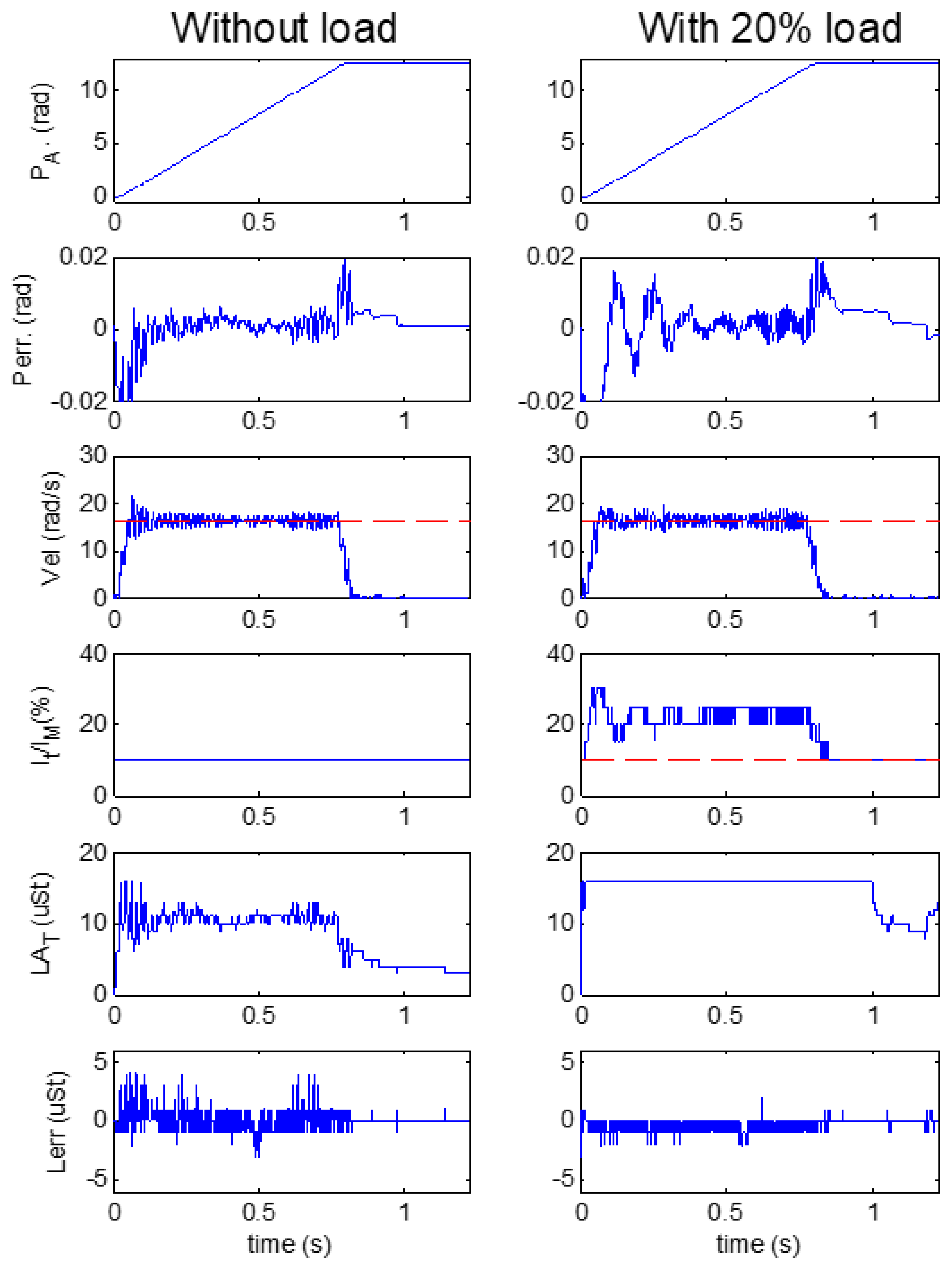
4.4. Trajectory Test in Different Load Conditions

The trajectory generator of Figure 4 was programmed to produce a forward movement of 2π rad, with a constant acceleration/deceleration of 270 rad/s2 and a maximum velocity of 16.4 rad/s. The experiment was repeated with the motor free, i.e., no load except the encoder, and with the motor connected to a load. The load was realized with a weight suspended by wire wrapped around the shaft. In the movement, the motor raised up the weight generating a torque that corresponds to about 20% of the full motor capacity. Figure 9 reports the parameters acquired in the FPGA every 300 μs. Left and right columns report the measurements obtained without and with the load, respectively. The errors are expressed as mean ± standard deviation calculated on the samples population of the corresponding measurement.
The measured position PA is reported on the 1st row of Figure 9. The movement lasted 0.83 s; it featured a typical “S” shape, which is barely visible because of the high acceleration used. The position error Perr is shown in the 2nd row. In the experiment with no load, the error peaks up to ±0.2 rad in the high acceleration/deceleration regions, but it is as low as 1 ± 2 mrad in the constant velocity region. The motor reacts to the acceleration in presence of load with an oscillation error of ±0.02 rad, which damps down in 200 ms. In the remaining part of the constant velocity region, the error is the same as in the no-load condition. With load, after the movement, the controller recovers the right steady position a bit more slowly with respect to no-load condition.
The measured velocity shows the expected trapezoidal shape with some oscillations. The velocity is reported on the 3rd row of Figure 9, where it is compared to the target value, i.e., 16.4 rad/s, highlighted by the red horizontal segment. The velocity error was 0.01 ± 0.58 rad/s with no load, and 0.02 ± 0.85 rad/s with the load.
Without load, as expected, the current was set to its 10% minimum (4th row, left) and the torque was modulated by the load angle ( L A T 5th row, left), which, during the movement, was about 10 μ-steps and reduced in the steady region. The error on the load angle (Lerr, 6th row, left) was 0.03 ± 0.7 μ-step. With load, during the movement, the load angle was fixed to its maximum, i.e., 16 μ-step corresponding to 90° ( L A T 5th row, right), and the torque was modulated by the current (4th row, right), which was about 20% of the nominal value. At the end of the movement, when the torque required reduced, the current went down to 10% and the torque was again modulated by the angle. In this case, the error on the load angle was −0.4 ± 0.5 μ-step.

5. Discussion and Conclusions

Stepper motors are pervasive in modern applications; however, their use of open loops has several drawbacks. This work aims at a simple closed-loop method for overcoming such disadvantages. The method is fully compatible with the commercial monolithic devices typically used for open-loop drive of stepper motors, so that the generation and control of phase currents can be achieved on such devices.
The heart of the method is represented by the loop control (5). It comprises a few simple operations that are executed at a high rate. In fact, the ripple on the load angle error depends on the loop execution period T, according to (6). In this implementation, we used T = 50 μs, which, for example, allowed us to reduce the load angle error to less than −5 μ-step (about 1/100 rad) for a rotor velocity up to 750 rev/min. The proposed method achieves a very low static error both in load (0.05 ± 1.3 mrad) and no-load (0.09 ± 1.4 mrad) conditions, as measured in the experiment reported in Section 4.4). This error can be compared, for example, to those obtained by similar closed loop controllers described in [19] and [20], where static errors of 0.5° (~8 mrad) and 0.2° (3.5 mrad) are reported, respectively. The position error present during constant velocity movement (see experiment 4.4) is similar or lower to that shown in Figure 5 of [11], where a different FOC closed loop controller for stepper motors is presented. The controller presented in [11], among other differences, is based on a microcontroller where the control loop runs at T = 350 μs, with respect to T = 50 μs proposed here.
The high execution rate used in this work would be critical—if not unfeasible—in full microprocess implementation; hence, the use of an FPGA, as proposed here. On the other hand, the remaining tasks, e.g., current calculation, are more time-relaxed, and a C-like microprocessor approach makes the development and the debug easier. The use of the FPGA fabric and the soft processor answers to both requirements with a single electronics device. However, in cases where FPGA resources must be saved, a full VHDL controller implementation is feasible.
Several improvements can be made to the proposed method, like the damping of the motor resonances [21], the use of optimal load angle [22], the sensor-less angle measurement [23,24], ripple reduction [25], and others.
The proposed method represents a simple and economic implementation of closed-loop control, which yields significant improvement in stepper motor performance with respect to the typical open-loop approach.

Author Contributions

Conceptualization, Methodology, Writing paper, Funding Acquisition: S.R.; Software, Investigation, Data Curation: V.M.

Funding

This work is part of the MIPEC project, CUP 4421.02102014.072000051, funded by the Tuscany Region government through the FAR-FAS 2014 program.

Acknowledgments

Authors thank Microtest srl (Altopascio, Italy) for managing the funding project, and the Industrial Engineering Department (DIEF) of the University of Florence for their advices in the realization of the mechanical set-up.

Conflicts of Interest

The authors declare no conflict of interest. The funders had no role in the design of the study; in the collection, analyses, or interpretation of data; in the writing of the manuscript, and in the decision to publish the results.

References

  1. Athani, V.V. Stepper Motors: Fundamentals, Applications and Design; New Age International: New Delhi, India, 2005; ISBN 81-224-1006-5. [Google Scholar]
  2. Robert, B.; Feki, M. Control of the stepping motor. In Control of Non-Con- Conventional Synchronous Motors; Louis, J.P., Ed.; Wiley-ISTE: London, UK, 2012; ISBN 978-1-848-21331-9. [Google Scholar]
  3. Gaan, D.R.; Kumar, M.; Sudhakar, S. Real-time precise position tracking with stepper motor using frequency modulation based microstepping. IEEE Trans. Ind. Appl. 2018, 54, 693–701. [Google Scholar] [CrossRef]
  4. Derammelaere, S.; Vervisch, B.; Cottyn, J.; Vanwalleghem, B.; Cox, P.; De Belie, F.; Stockman, K.; Vandevelde, L.; Van Den Abeele, G. The efficiency of hybrid stepping motors. IEEE Ind. Appl. Mag. 2014, 20, 50–60. [Google Scholar] [CrossRef]
  5. Krause, P.; Wasynczuk, O.; Sudhoff, S.; Pekarek, S. Analysis of Electric Machinery and Drive Systems; IEEE Press Wiley: Hoboken, NJ, USA, 2013; ISBN 978-1-118-02429-4. [Google Scholar]
  6. Wang, F.; Zhang, Z.; Mei, X.; Rodríguez, J.; Kennel, R. Advanced control strategies of induction machine: Field oriented control, direct torque control and model predictive control. Energies 2018, 11, 120. [Google Scholar] [CrossRef]
  7. Blackburn, J.L. Symmetrical Components for Power Systems Engineering; Marcel Dekker: New York, NY, USA, 1993. [Google Scholar]
  8. Monmasson, E.; Cirstea, M.N. FPGA design methodology for industrial control systems—A review. IEEE Trans. Ind. Electron. 2007, 54, 1824–1842. [Google Scholar] [CrossRef]
  9. Ricci, S.; Meacci, V.; Birkhofer, B.; Wiklund, J. FPGA-based system for in-line measurement of velocity profiles of fluids in industrial pipe flow. IEEE Trans. Ind. Electron. 2017, 64, 3997–4005. [Google Scholar] [CrossRef]
  10. Astrom, K.J.; Hagglund, T. Advanced PID Control; ISA-The Instrumentation, Systems, and Automation Society: Research Triangle Park, CA, USA, 2006; ISBN 13: 978-1556179426. [Google Scholar]
  11. Kim, W.; Yang, C.; Chung, C.C. Design and implementation of simple field-oriented control for permanent magnet stepper motors without DQ transformation. IEEE Trans. Magn. 2011, 47, 4231–4234. [Google Scholar] [CrossRef]
  12. Le, K.M.; Hoang, H.V.; Jeon, J.W. An advanced closed-loop control to improve the performance of hybrid stepper motors. IEEE Trans. Power Electron. 2016, 32, 7244–7255. [Google Scholar] [CrossRef]
  13. Jimenez-Fernandez, A.; Jimenez-Moreno, G.; Linares-Barranco, A.; Dominguez-Morales, M.J.; Paz-Vicente, R.; Civit-Balcells, A. A neuro-inspired spike-based PID motor controller for multi-motor robots with low cost FPGAs. Sensors 2012, 12, 3831–3856. [Google Scholar] [CrossRef] [PubMed]
  14. Le, Q.N.; Jeon, J.W. Neural-network-based low-speed-damping controller for stepper motor with an FPGA. IEEE Trans. Ind. Electron. 2009, 57, 3167–3180. [Google Scholar] [CrossRef]
  15. Matsui, N.; Nakamura, M.; Kosaka, T. Instantaneous torque analysis of hybrid stepping motor. IEEE Trans. Ind. Electron. 1996, 32, 1176–1182. [Google Scholar] [CrossRef]
  16. Cetin, E.; Daldaban, F. Analyzing the profile effects of the various magnet shapes in axial flux PM motors by means of 3D-FEA. Electronics 2018, 7, 13. [Google Scholar] [CrossRef]
  17. Kazmierkowski, M.P.; Malesani, L. Current control techniques for three-phase voltage-source PWM converters: A survey. IEEE Trans. Ind. Electron. 1998, 45, 691–703. [Google Scholar] [CrossRef]
  18. Ricci, S.; Meacci, V.; Russo, D.; Matera, R. Encoder-Motor Misalignment Compensation for Closed-Loop Hybrid Stepper Motor Control. In Proceedings of the 6th International Conference Applications in Electronics Pervading Industry Environment Society (APPLEPIES 2018), Pisa, Italy, 26–27 September 2018. [Google Scholar]
  19. Lu, W.; Wang, Q.; Ji, K.; Dong, H.; Lin, J.; Qian, J. Research on closed-loop drive system of two-phase hybrid step motor based on SVPWM. In Proceedings of the 2016 IEEE Vehicle Power and Propulsion Conference (VPPC), Hangzhou, China, 17–20 October 2016. [Google Scholar]
  20. Liu, G.F.; Li, H.W. Design of stepper motor position control system based on DSP. In Proceedings of the 2017 2nd International Conference on Machinery, Electronics and Control Simulation (MECS 2017), Dubai, UAE, 24–25 June 2017. [Google Scholar]
  21. Crnosija, P.; Kuzmanovic, B.; Ajdukovic, S. Microcomputer implementation of optimal algorithms for closed-loop control of hybrid stepper motor drives. IEEE Trans. Ind. Electron. 2000, 47, 1319–1325. [Google Scholar] [CrossRef]
  22. Tsui, K.W.H.; Cheung, N.C.; Yuen, K.C.W. Novel modeling and damping technique for hybrid stepper motor. IEEE Trans. Ind. Electron. 2009, 56, 202–211. [Google Scholar] [CrossRef]
  23. Derammelaere, S.; Vervisch, B.; De Viaene, J.; Stockman, K. Sensorless load angle control for two-phase hybrid stepper motors. Mechatronics 2017, 43, 6–17. [Google Scholar] [CrossRef]
  24. Gutierrez-Villalobos, J.M.; Rodriguez-Resendiz, J.; Rivas-Araiza, E.A.; Martínez-Hernández, M.A. Sensorless FOC performance improved with on-line speed and rotor resistance estimator based on an artificial neural network for an induction motor drive. Sensors 2015, 15, 15311–15325. [Google Scholar] [CrossRef] [PubMed]
  25. Gómez-Espinosa, A.; Hernández-Guzmán, V.M.; Bandala-Sánchez, M.; Jiménez-Hernández, H.; Rivas-Araiza, E.A.; Rodríguez-Reséndiz, J.; Herrera-Ruíz, G. A new adaptive self-tuning Fourier coefficients algorithm for periodic torque ripple minimization in permanent magnet synchronous motors (PMSM). Sensors 2013, 13, 3831–3847. [Google Scholar] [CrossRef] [PubMed]
Figure 1. In a stepper motor the torque is related to the load angle θ L , present between the rotor magnet, θ R , and the current field, θ I . The target load angle θ L t is obtained by advancing of θ I n the current field θ i .
Electronics 07 00242 g001
Figure 2. Procedure of the proposed control method.
Electronics 07 00242 g002
Figure 3. The electronics system is composed of the DECA Max10 and the EVLPOWERStep01 developing boards connected through a homemade interface board. A second drive board can be connected to simultaneously drive 2 motors.
Electronics 07 00242 g003
Figure 4. FPGA implementation of the proposed method. Control step 1 and Control step 2 refer to the calculations reported in the corresponding steps of Figure 2.
Electronics 07 00242 g004
Figure 5. Timing of the commands sent to the power driver.
Electronics 07 00242 g005
Figure 6. Experimental set-up with the stepper motor (left) connected to the encoder (right) through a flexible mechanical coupling (center).
Electronics 07 00242 g006
Figure 7. Rotor (RP) and Current (CP) Positions, Step Increment ( S T i ), and measured Load Angle ( L A M ) with fixed 2.5 A phase currents and 16 µ-steps target load angle ( L A T ).
Electronics 07 00242 g007
Figure 8. The rotor position is controlled at position 0. An external positive torque is applied and released at t = 0 (vertical dashed line). From top to bottom, physical Rotor position PA, motor current ratio (It/IM), target (LAT) and measured (LAM) load angles, and load angle error (Err), are reported.
Electronics 07 00242 g008
Figure 9. Movement of 2π rad with acceleration of 270 rad/s2 and maximum velocity of 16.4 rad/s, performed with motor free (left column) and with a load of 20% motor capacity (right column). From top to bottom, Shaft position (PA), Position error (Perr), Velocity (Vel), motor current ratio (It/IM), target load angle (LAT), and load angle error (Lerr), are reported.
Electronics 07 00242 g009
Table 1. Torque modulation control strategy (1/2).
ConditionControl StrategyAngleCurrentTorque
Γ E Γ M > 0.1 Angle fixed, Γ E modulated by I θ L = ± π 2 I Γ E = ± K t I (2a)
Γ E Γ M < 0.1 Current fixed Γ E controlled by θ L θ L I = I M 10 Γ E = K t I M 10 sin ( θ L ) (2b)
Table 2. Torque modulation control strategy (2/2).
ConditionControl StrategyAngleCurrentTorque
Γ E Γ M > 0.1 Angle fixed, Γ E modulated by I θ L = ± π 2 I = Γ E K t = Γ E Γ M I M Γ E (3a)
Γ E Γ M < 0.1 Current fixed Γ E controlled by θ L θ L = sin 1 ( 10 · Γ E Γ M ) I = I M 10 Γ E (3b)
Table 3. FPGA Resources employed by the control system.
FPGA BlokLogic CellDedicated RegMemory BitsDSP
Nios50173079195,0006
StepManager4530--
LoadAngle + Mapper Blk 349132--
Enc CNT16767--
Table 4. Features of the Motor and the Encoder used in the experimental set-up.
MOTOR
ModelM1233041
ManufacturerLam Technologies, Florence, Italy
FlangeNEMA23
Step angle1.8° (200 step/rev)
Hold Torque1.1 N·m
Detent Torque0.035 N·m
Current4.2 A
Phase Resistance0.4 Ohm
Phase Inductance1.2 mH
Rotor Inertia0.280 kg·cm−2
ENCODER
ModelREV621
ManufacturerElap, Milan, Italy
Zero referenceyes
Pulse/revolution10,000

