Non-Orthogonal Resource Sharing Optimization for D2D Communication in LTE-A Cellular Networks: A Fractional Frequency Reuse-Based Approach


Abstract
:
1. Introduction
2. Contribution
3. Related Works
4. Overview of Device-to-Device Communication
- Device relaying with operator-controlled link establishment: A device in a remote area or far away from the eNB can communicate with an eNB using another device as a relay. In this communication scenario, an eNB can corroborate the relaying devices and thus preserve the privacy as well as frequency allocation of the devices.
- Direct D2D communication with operator-controlled link establishment: A network assisted link can communicate with each other bypassing the eNB. The eNB controls the connections, frequency allocation and pecuniary communication between devices.
- Device relaying with device-controlled link establishment: An eNB has no control over the device communication. Devices communicate with each other by using relays between them.
- Direct D2D communication with device-controlled link establishment: An eNB has no control over the device communication. Communication between devices is managed by the devices themselves.
- Inband D2D communication/LTE Direct: D2D communication occurs in a cellular-licensed spectrum in a dedicated mode (overlay mode) or shared mode (underlay mode).
- Outband D2D communication: D2D communication occurs in an unlicensed spectrum endorsed by other wireless technologies such as WiFi or Bluetooth.
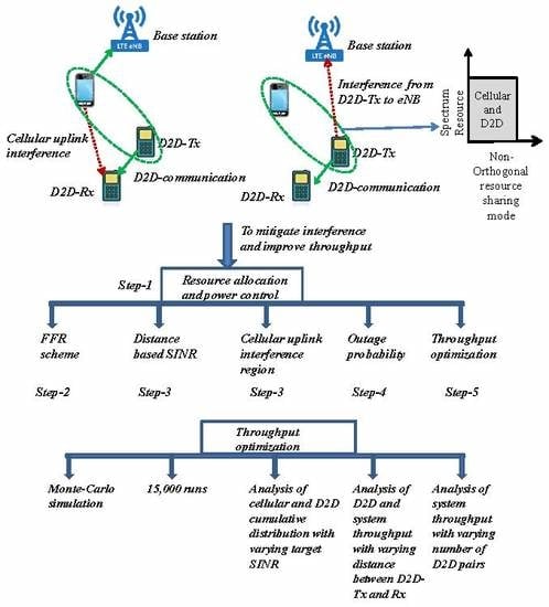
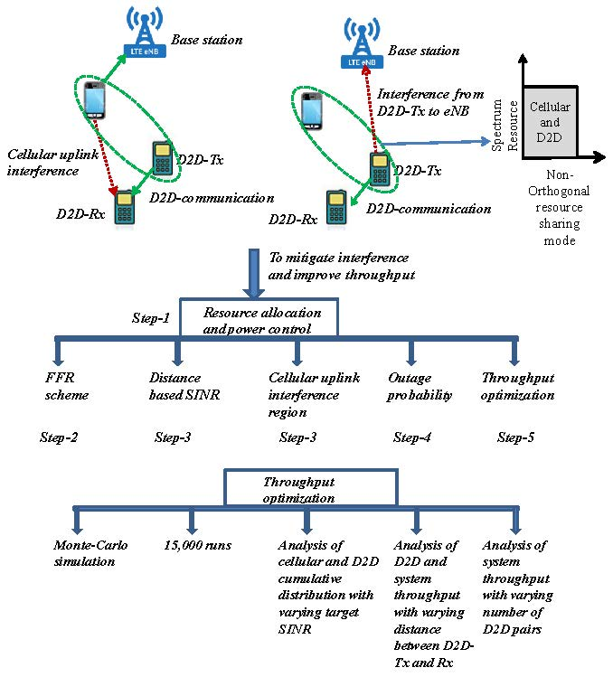
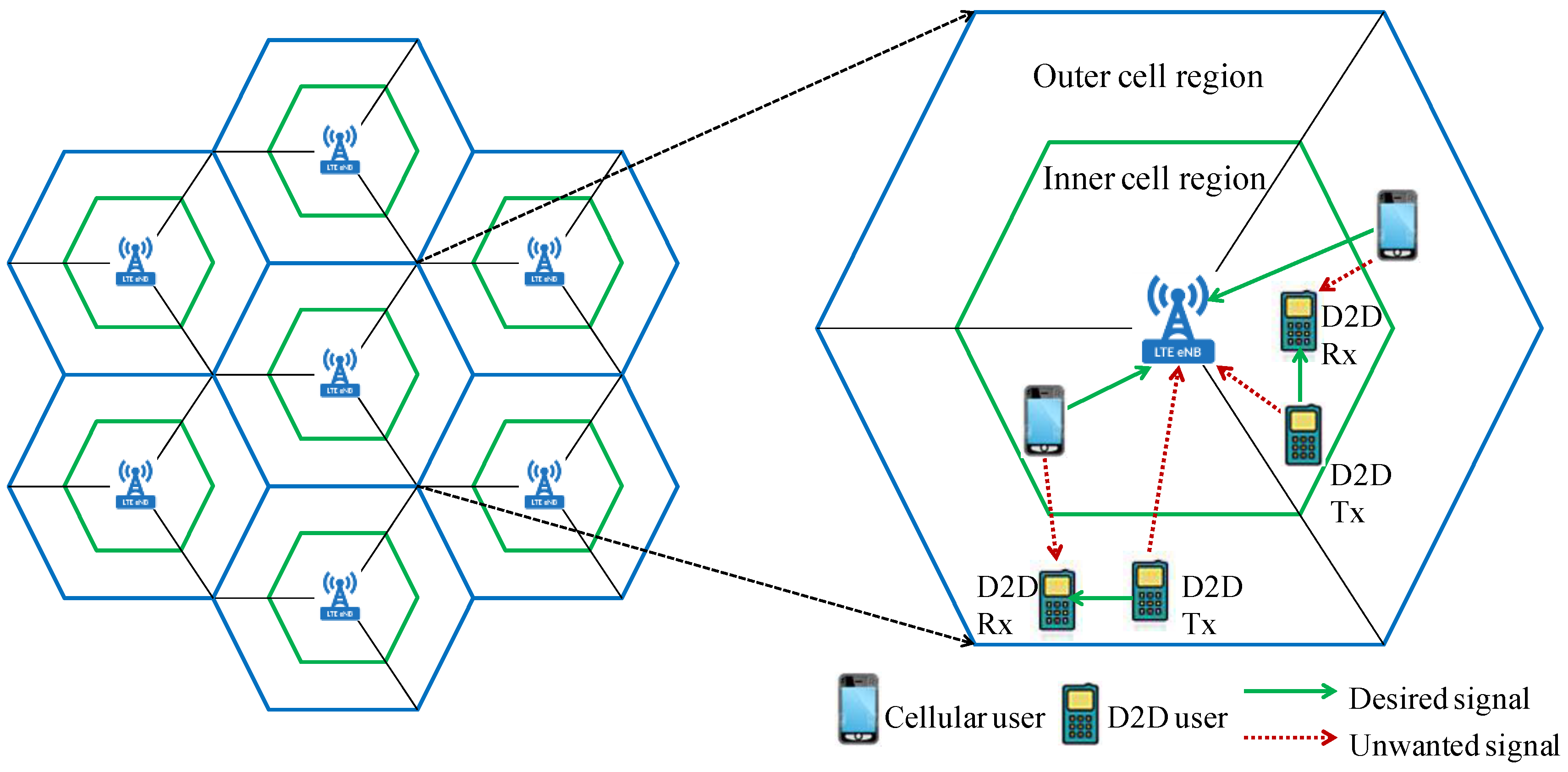
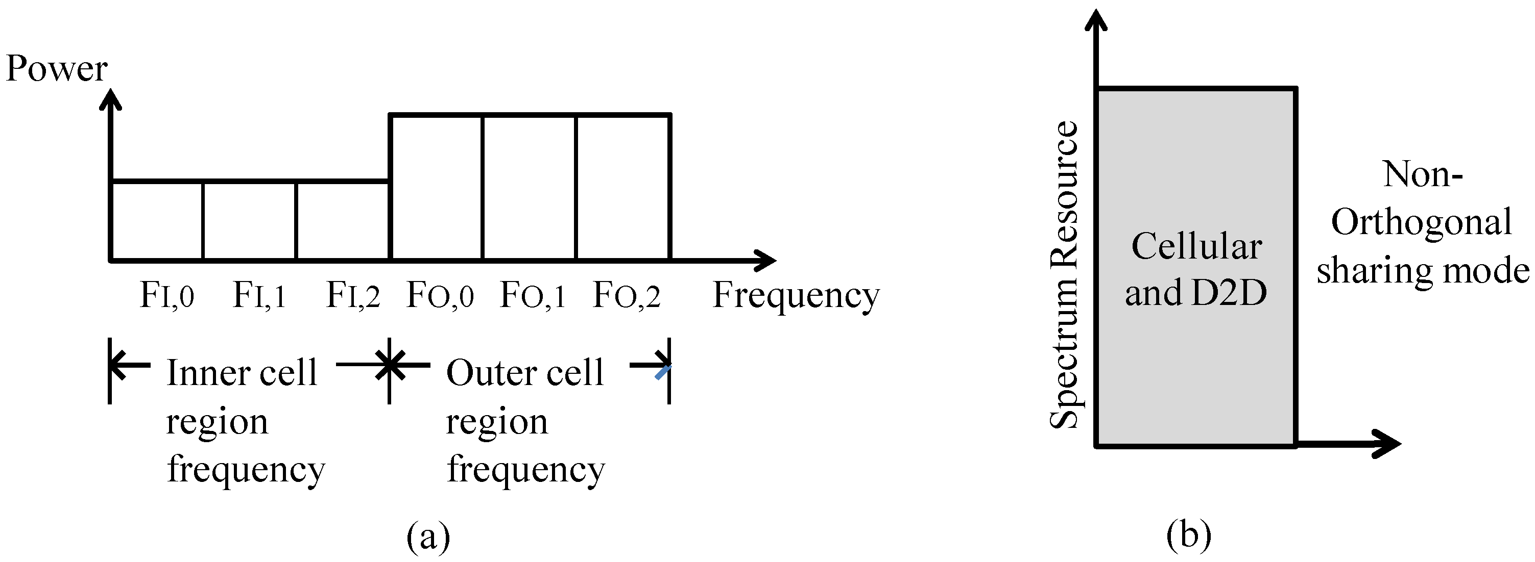
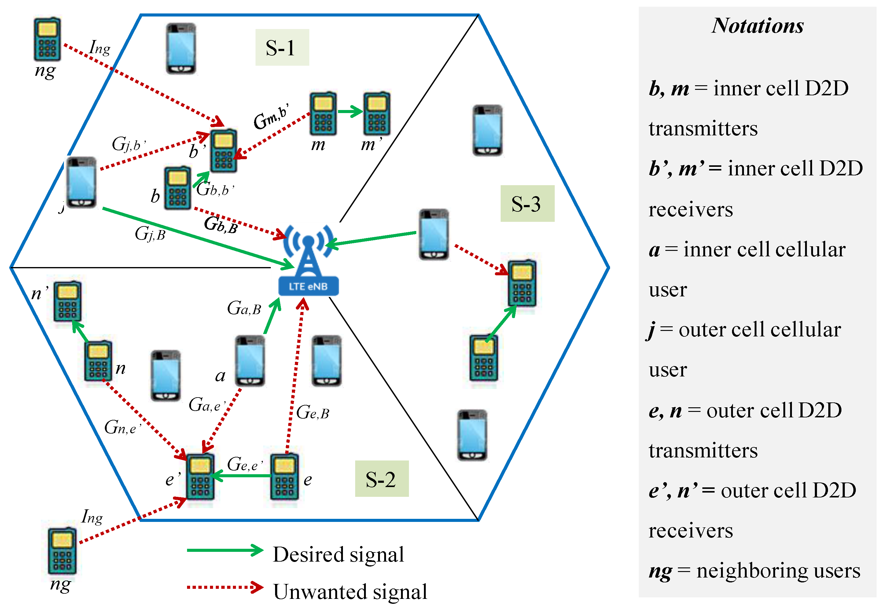
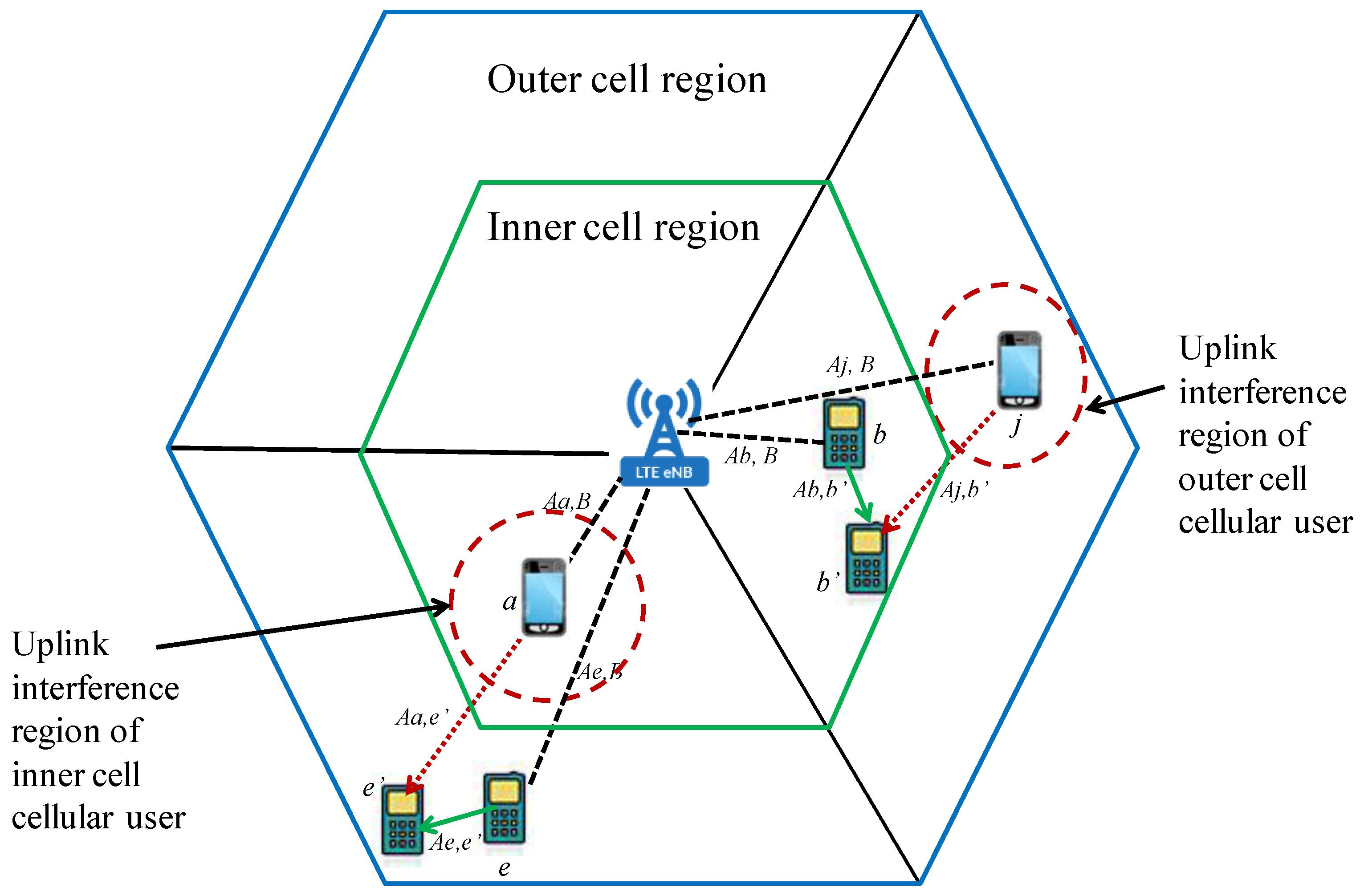
5. Network Model
| Algorithm 1 Working of the Proposed Resource Allocation and Power Control Scheme |
|
6. Problem Formulation
6.1. Interference Analysis
- For the inner cell user: The received SINR for the inner cell cellular user and the D2D pair is given byrespectively, where is the interference to D2D receiver in the inner cell region and can be expressed as follows:The interference from the neighboring cells can be denoted as
- For the outer cell user: The received SINR for the outer cell cellular user and the D2D pair is given byrespectively, where is the interference to user D2D receiver and can be listed as
6.2. Outage Probability Analysis
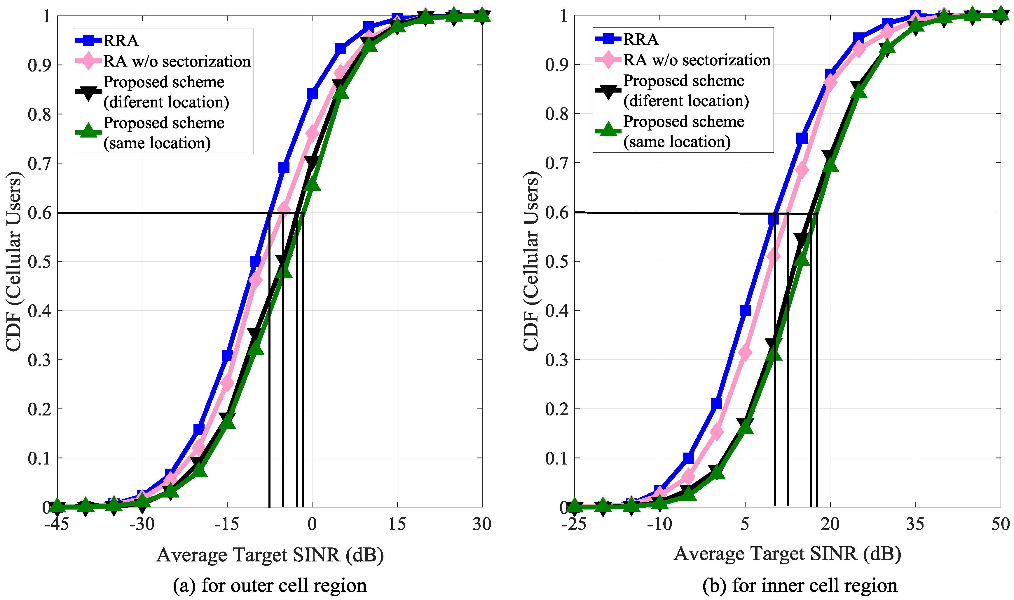
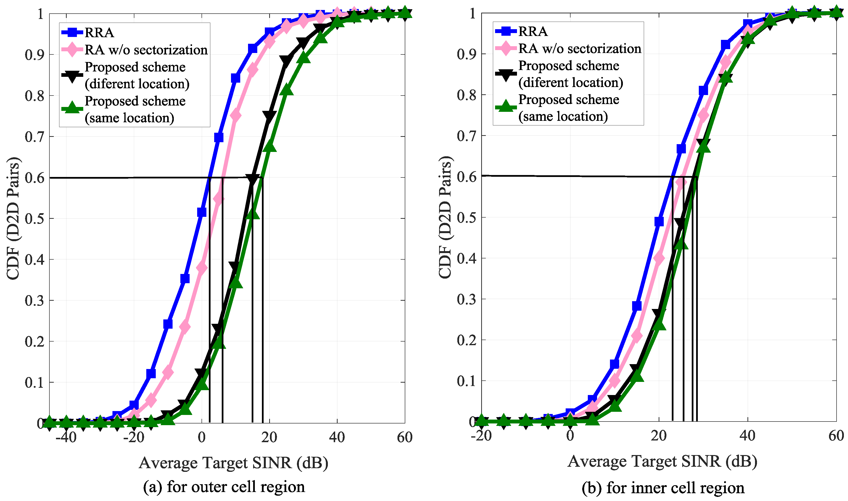
- For the inner cell user: The outage probability for the cellular user in the inner cell region, in terms of the received SINR is given aswhere , and are the received SINR threshold, predefined outage probability requirement of the cellular user and D2D user, respectively.
- For the outer cell user: The outage probability for the cellular user and the D2D pair in the outer cell region in terms of their SINRs is expressed aswhere , and are the received SINR threshold, predefined outage probability requirement of the cellular user and D2D user, respectively.
7. System Throughput Optimization
8. Channel Model
9. Computational Complexity and Use Case Scenario of the Proposed Scheme
9.1. Computational Complexity Analysis
9.2. Use Case Scenario of the Proposed Scheme
10. Performance Evaluation
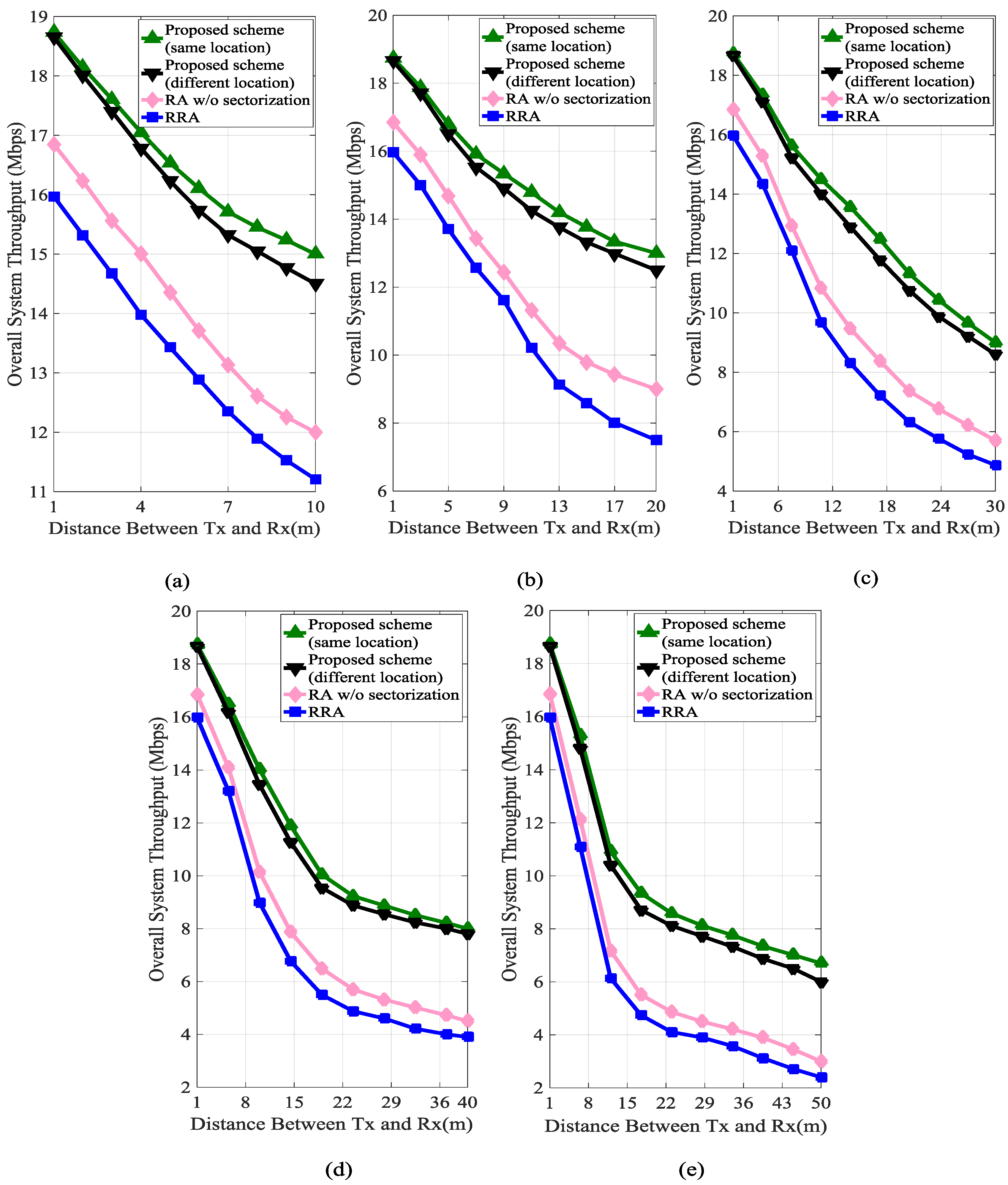
- When the D2D pairs are more than the cellular users (D2D > C) as given in Table 1, and the D2D transmitter (Tx) and receiver (Rx) are located in different cell sections: In this scenario, all the available cellular resources can be reused by the D2D pairs. This results in the maximum utilization of the spectrum, but the performance of the D2D communication may not be efficient, the number of available resources to be reused by the D2D pairs is less. As the D2D Tx and Rx are located in different sections of the cell, the D2D Rx will be interfered more by the nearby cellular users.
- When the D2D pairs are more than the cellular users (D2D > C) as given in Table 1, and the D2D transmitter (Tx) and receiver (Rx) are located in same cell section: In this scenario, as both the D2D Tx and Rx are located in the same cell section, the D2D communication have less interfering devices to the D2D Rx. This scenario is more efficient than scenario 1.
- When the number of cellular users are more than the number of D2D Pairs (C > D2D) as given in Table 2, and the D2D transmitter (Tx) and receiver (Rx) are located in different cell sections: Here, more cellular links will not be utilized by the D2D pairs as the number of sources is high but the consumers are few. However, when some of the available cellular links are disconnected or are in sleep mode, the D2D pair can have other options to choose the remaining active cellular links. This condition cannot apply to the first and second scenarios.
- When the number of cellular users is more than the number of D2D Pairs (C > D2D) as given in Table 2, and the D2D transmitter (Tx) and receiver (Rx) are located in the same cell section: As the D2D Tx and Rx exist in the same cell section, the communication will have less interference.
10.1. Simulation Parameters and Values
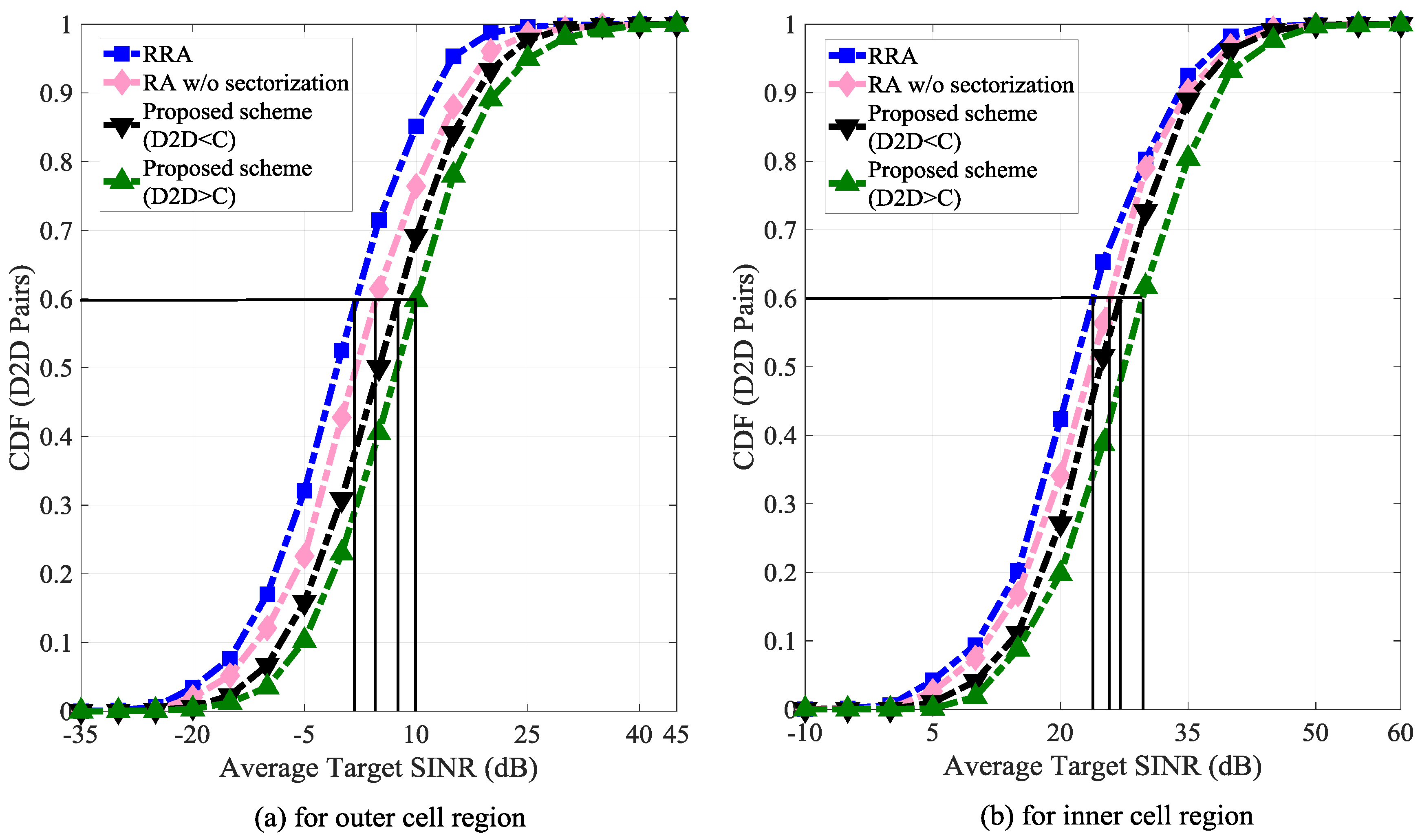
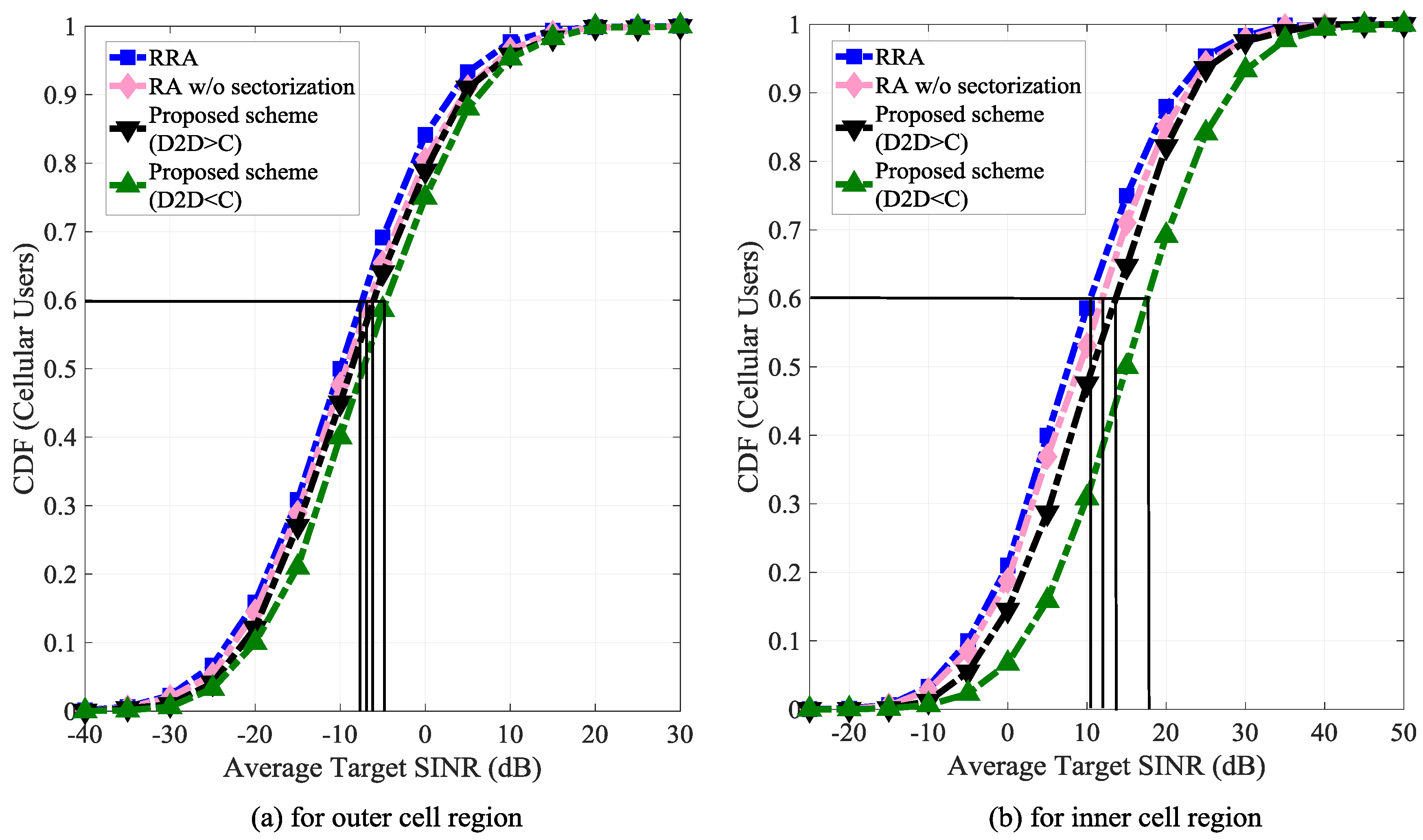
10.2. Simulation Results and Discussions
11. Conclusions
Author Contributions
Funding
Conflicts of Interest
References
- Bojkovic, Z.; Bakmaz, B.; Bakmaz, M. Recent Trends in Emerging Technologies toward 5G Networks. In Proceedings of the 9th International Conference on Circuits, Systems, Signal and Telecommunications, Dubai, United Arab Emirates, 22–24 February 2015. [Google Scholar]
- Duong, Q.; Shin, Y.; Shin, O.-S. Distance-based resource allocation scheme for device-to-device communications underlaying cellular networks. AEU Int. J. Electron. Commun. 2015, 69, 1437–1444. [Google Scholar] [CrossRef]
- Zhao, W.; Wang, S. Low complexity power allocation for device-to-device communication underlaying cellular networks. In Proceedings of the 2014 IEEE International Conference on Communications (ICC), Sydney, NSW, Australia, 10–14 June 2014. [Google Scholar]
- Ningombam, D.D.; Pyun, J.; Hwang, S.; Shin, S. Fractional frequency reuse scheme for interference mitigation in device-to-device communication underlying LTE-A networks. In Proceedings of the 2017 51st Asilomar Conference on Signals, Systems, and Computers, Pacific Grove, CA, USA, 29 October–1 November 2017. [Google Scholar]
- Katsinis, G.; Tsiropoulou, E.E.; Papavassiliou, S. Joint Resource Block and Power Allocation for Interference Management in Device to Device Underlay Cellular Networks: A Game Theoretic Approach. Mobile Net. Appl. 2016, 22, 539–551. [Google Scholar] [CrossRef]
- Lianghai, J.; Man, L.; Schotten, H.D. Context-aware cluster based device-to-device communication to serve machine type communications. In Proceedings of the 2017 IEEE International Conference on Communications Workshops (ICC Workshops), Paris, France, 21–25 May 2017. [Google Scholar]
- Feng, D.; Lu, L.; Yuan-Wu, Y.; Li, G.Y.; Feng, G.; Li, S. Device-to-Device Communications Underlaying Cellular Networks. IEEE Trans. Commun. 2013, 61, 3541–3551. [Google Scholar] [CrossRef]
- Kuruvatti, N.P.; Schotten, H.D. Post-resource sharing power allocation in cellular networks to coexist with D2D underlay. In Proceedings of the 2016 7th International Conference on the Network of the Future (NOF), Buzios, Brazil, 16–18 November 2016. [Google Scholar]
- Katsinis, G.; Tsiropoulou, E.E.; Papavassiliou, S. On the Problem of Resource Allocation and System Capacity Evaluation via a Blocking Queuing Model in D2D Enabled Overlay Cellular Networks. In Int. Conf. on Ad-Hoc Net. and Wire; Papavassiliou, S., Ruehrup, S., Eds.; Springer: Cham, Switzerland, 2015; pp. 76–89. [Google Scholar]
- Zhe, L. Performance Analysis of Network Assisted Neighbor Discovery Algorithms. Master’s Thesis, Cardiff University, Cardiff, UK, 2012. [Google Scholar]
- Katsinis, G.; Tsiropoulou, E.E.; Papavassiliou, S. On the Performance Evaluation of Distributed Resource Block and Power Allocation in D2D-enabled Multi-Cell Networks. In Proceedings of the 14th ACM Symposium on Performance Evaluation of Wireless Ad Hoc, Sensor and Ubiquitous Networks, Miami, FL, USA, 21–25 November 2017. [Google Scholar]
- Ningombam, D.D.; Shin, S. Radio resource allocation and power control scheme to mitigate interference in device-to-device communications underlaying LTE-A uplink cellular networks. In Proceedings of the 2017 International Conference on Information and Communication Technology Convergence (ICTC), Jeju, Korea, 18–20 October 2017. [Google Scholar]
- Sattiraju, R.; Klein, A.; Ji, L.; Zhou, C.; Bulakci, O.; Eichinger, J.; Kuruvatti, N.P.; Schotten, H.D. Virtual Cell Sectoring for Enhancing Resource Allocation and Reuse in Network Controlled D2D Communication. In Proceedings of the 2015 IEEE 81st Vehicular Technology Conference (VTC Spring), Glasgow, UK, 11–14 May 2015. [Google Scholar]
- Kim, T.-S.; Lee, K.-H.; Ryu, S.; Cho, C.-H. Resource Allocation and Power Control Scheme for Interference Avoidance in an LTE-Advanced Cellular Networks with Device-to- Device Communication. Int. J. Control Autom. 2013, 6, 10. [Google Scholar]
- Li, X.; Shankaran, R.; Orgun, M.A.; Fang, G.; Xu, Y. Resource Allocation for Underlay D2D Communication With Proportional Fairness. IEEE Trans. Veh. Technol. 2018, 67, 6244–6258. [Google Scholar] [CrossRef]
- Zhang, Z.; Hu, R.Q.; Qian, Y.; Papathanassiou, A. D2D Communication Underlay in Uplink Cellular Networks with Fractional Power Control and Fractional Frequency Reuse. In Proceedings of the 2015 IEEE Global Communications Conference (GLOBECOM), San Diego, CA, USA, 6–10 December 2015. [Google Scholar]
- Zhu, H.; Wang, J. Device-to-device communication in cellular networks with fractional frequency reuse. In Proceedings of the 2014 IEEE International Conference on Communications (ICC), Sydney, NSW, Australia, 10–14 June 2014. [Google Scholar]
- Sharma, S.; Gupta, N.; Bohara, V.A. OFDMA-Based Device-to-Device Communication Frameworks: Testbed Deployment and Measurement Results. IEEE Access 2018, 6, 12019–12030. [Google Scholar] [CrossRef]
- Jiang, F.; Wang, B.-C.; Sun, C.-Y.; Liu, Y.; Wang, X. Resource Allocation and Dynamic Power Control for D2D Communication Underlaying Uplink Multi-Cell Networks. Wirel. Netw. 2016, 24, 549–563. [Google Scholar] [CrossRef]
- Tehrani, M.N.; Uysal, M.; Yanikomeroglu, H. Device-to-device communication in 5G cellular networks: Challenges, solutions, and future directions. IEEE Commun. Mag. 2014, 52, 86–92. [Google Scholar] [CrossRef]
- An overview of device-to-device communication in cellular networks. Available online: https://reader.elsevier.com/reader/sd/A6F2850A17C596B03F981C619FA194DEB33914A943A688F4E45C913C154179879E4307972A65B27E22658F4E7BBDEEA5 (accessed on 14 August 2018).
- Kim, J.; Karim, N.A.; Cho, S. An Interference Mitigation Scheme of Device-to-Device Communications for Sensor Networks Underlying LTE-A. Sensors 2017, 17, 1088. [Google Scholar] [Green Version]
- Shah, S.T.; Gu, J.; Hasan, S.F.; Chung, M.Y. SC-FDMA-based resource allocation and power control scheme for D2D communication using LTE-A uplink resource. EURASIP J. Wirel. Commun. Netw. 2015, 2015, 137. [Google Scholar] [CrossRef]
- Alouini, M.-S.; Goldsmith, A.J. Area spectral efficiency of cellular mobile radio systems. IEEE Trans. Veh. Technol. 1999, 48, 1047–1066. [Google Scholar] [CrossRef]
- Li, X.; Wang, Z.; Sun, Y.; Gu, Y.; Hu, J. Mathematical Characteristics of Uplink and Downlink Interference Regions in D2D Communications Underlaying Cellular Networks. Wirel. Pers. Commun. 2017, 93, 917–932. [Google Scholar] [CrossRef]
- Bąkowski, K.; Wesołowski, K.; Rodziewicz, M. Simulation Tools for the Evaluation of Radio Interface Technologies for IMT-Advanced and Beyond. In Simulation Technology in Networking and Communication; Pathan, A.-S., Monowar, M., Khan, S., Eds.; CRC Press: Boca Raton, FL, USA, 2014; ISBN 978-1-4822-2549-5. [Google Scholar]


| Cell Region | Number of Devices |
|---|---|
| Cell inner region | D2D = 15, C = 40 |
| Cell outer region | D2D = 50, C = 10 |
| Cell Region | Number of Devices |
|---|---|
| Cell inner region | D2D = 15, C = 50 |
| Cell outer region | D2D = 30, C = 30 |
| Parameter | Value |
|---|---|
| Cell outline | 7-cells, hexagonal framework |
| evolved-NodeB (Enb) transmission power | 40–46 dBm(inner cell) |
| eNB transmission power | 43–49 dBm(outer cell) |
| D2D transmission power | 8–15 dBm |
| Noise power | −174 dBm/Hz |
| D2D pair distance | 1–50 m |
| Carrier frequency | 2 GHz |
| Cell radius | 500 m |
| Uplink bandwidth | 5 MHz |
| Path loss exponent | 4 |
| Antenna type | 3°–120° directional antennas |
| Monte-Carlo simulation runs | 15,000 |
© 2018 by the authors. Licensee MDPI, Basel, Switzerland. This article is an open access article distributed under the terms and conditions of the Creative Commons Attribution (CC BY) license (http://creativecommons.org/licenses/by/4.0/).
Share and Cite
Ningombam, D.D.; Shin, S. Non-Orthogonal Resource Sharing Optimization for D2D Communication in LTE-A Cellular Networks: A Fractional Frequency Reuse-Based Approach. Electronics 2018, 7, 238. https://doi.org/10.3390/electronics7100238
Ningombam DD, Shin S. Non-Orthogonal Resource Sharing Optimization for D2D Communication in LTE-A Cellular Networks: A Fractional Frequency Reuse-Based Approach. Electronics. 2018; 7(10):238. https://doi.org/10.3390/electronics7100238
Chicago/Turabian StyleNingombam, Devarani Devi, and Seokjoo Shin. 2018. "Non-Orthogonal Resource Sharing Optimization for D2D Communication in LTE-A Cellular Networks: A Fractional Frequency Reuse-Based Approach" Electronics 7, no. 10: 238. https://doi.org/10.3390/electronics7100238