Article

Improving Real-Time Performance of Micro-ROS with Priority-Driven Chain-Aware Scheduling

by
Zilong Wang
,
Songran Liu
*,
Dong Ji
and
Wang Yi
School of Computer Science and Engineering, Northeastern University, Shenyang 110819, China
*
Author to whom correspondence should be addressed.
Electronics 2024, 13(9), 1658; https://doi.org/10.3390/electronics13091658
Submission received: 25 March 2024 / Revised: 22 April 2024 / Accepted: 24 April 2024 / Published: 25 April 2024
(This article belongs to the Special Issue Embedded Systems: Fundamentals, Design and Practical Applications)

Abstract

:
Micro-ROS is widely used to bridge the performance gap between resource-constrained microcontrollers and powerful computing devices in ROS-based robotic applications. After modeling the callback scheduling module and the communication module in micro-ROS, we found that there are some design flaws that significantly impact the real-time performance of micro-ROS. To improve the timing predictability and run-time efficiency of micro-ROS, we design and implement a priority-driven chain-aware scheduling system (PoDS) based on the existing micro-ROS architecture. The experimental results demonstrate that our proposed PoDS exhibits significantly improved real-time performance compared to the default micro-ROS.

1. Introduction

The Robot Operating System (ROS) [1] is a popular middleware framework for robotics, extensively explored in academia [2]. Due to its insufficient real-time capabilities and industry demands, the second generation of ROS, ROS 2 [3], has been in development since 2017. Although ROS 2 is the dominant framework for powerful computing devices, it lacks native support for microcontrollers due to its significant memory footprint. Microcontrollers typically feature a single CPU core and a few tens of kilobytes of RAM memory and use resource-optimized real-time operating systems (RTOS) [4]. Resource-constrained microcontrollers are commonly used in robotics for sensors and actuators, as well as for time-critical control functions, power efficiency, and safety considerations. The micro-ROS project was launched in 2018 [5] with the objectives of seamlessly integrating microcontrollers with ROS 2 and bringing all major ROS concepts into deeply embedded systems.
Micro-ROS is used to bridge the performance gap between resource-constrained microcontrollers and powerful computing devices in ROS-based robotic applications. In typical robotic application scenarios, microcontrollers are used for environmental sensing and actuator operation, owing to their low-latency real-time performance feature, while more powerful processors are employed for computationally intensive workloads. For example, a resource-constrained microcontroller equipped in the mobile robot running the micro-ROS stack transmits large volumes of sensor data to a remote computer running the ROS 2 stack [6]. Sensor data are processed by the high-performance computer, which performs complex operations such as modeling analysis and path planning. Following this analysis, the remote computer issues instructions to control the movement of the mobile robot and enable obstacle avoidance.
We have observed that the official website of micro-ROS only offers detailed tutorials on how to utilize the micro-ROS, but there is quite limited research on the comprehensive exploration of its internal mechanism or comparative evaluations with other embedded real-time systems. In this paper, we first conducted a detailed study of the micro-ROS source code and modeled the callback scheduling module and communication module in micro-ROS, then identified some design flaws that significantly impact its real-time performance.
(1) Low determinism: In micro-ROS, priority inversion issues may occur in both callback scheduling and data reception. This is primarily attributed to the inappropriate strategies adopted by the RCLC Executor and the data-processing module in micro-ROS, significantly influencing the deterministic end-to-end latency of specific chains.
(2) Inefficiency: In micro-ROS, synchronous management of callback execution and data transmission can result in CPU resource wastage when transmitting large volumes of data, leading to a considerable decrease in the run-time efficiency of micro-ROS.
To improve the run-time predictability and run-time efficiency of micro-ROS, we design and implement a priority-driven chain-aware scheduling system (PoDS) based on the existing micro-ROS architecture. Following experimental evaluation, PoDS demonstrates significantly improved real-time performance compared to micro-ROS.
Overall, this paper makes the following contributions.
  • Models of callback scheduling module and communication module in micro-ROS: Through detailed examination and analysis of the micro-ROS source code, we have discovered that the callback scheduling module implements a batch-based scheduling strategy. Moreover, data transmission within the communication module employs a sequential transmission strategy, and data reception adopts a FIFO-based data-processing strategy.
  • Problems present in current micro-ROS designs: After thorough analysis and validation, we have identified three critical issues that severely impact the run-time predictability and efficiency of micro-ROS, stemming from unreasonable micro-ROS designs.
  • Design principles of our proposed PoDS: Based on the micro-ROS architecture, we have designed and implemented a priority-driven chain-aware scheduling system named PoDS, which can effectively solve identified critical problems.
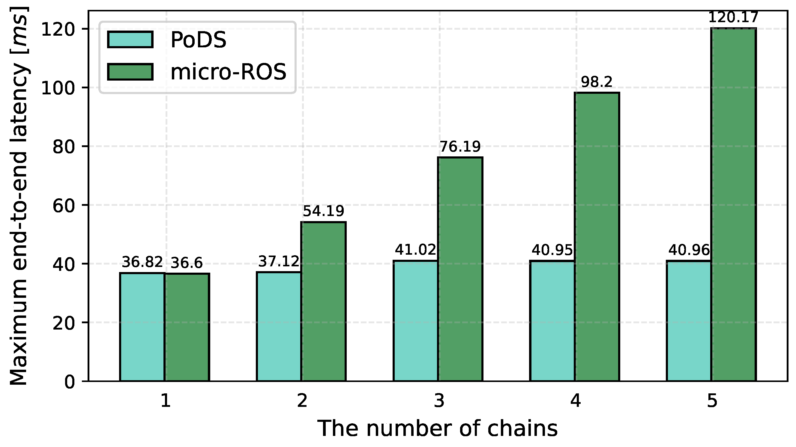
  • Performance evaluation of PoDS and micro-ROS: We conducted a comprehensive series of experiments to evaluate and compare the real-time performance of our proposed PoDS with that of micro-ROS. The results demonstrate that our PoDS exhibits superior and more stable performance compared to micro-ROS.

2. Background

In this section, we first introduce the organizational architecture of micro-ROS, and then we model the callback scheduling module and communication module of micro-ROS by exploring its project source code.

2.1. Micro-ROS Architecture

As depicted in Figure 1, micro-ROS is a collection of software libraries that reuses as many packages as possible from the standard ROS 2 stack [7]. The micro-ROS client library is built from the standard ROS 2 Client Support Library (RCL) and a new ROS 2 Client Library package (RCLC). The user can utilize ROS APIs implemented in C language provided by the micro-ROS client library to initialize several callbacks for specific functions. The micro-ROS stack can be employed with various open-source RTOS, such as FreeRTOS [8], Zephyr [9], and NuttX [10], but also comes with support for bare-metal use cases. In the middleware layer, the micro-ROS stack uses an open-source implementation of the DDS-XRCE standard developed by eProsima, named Micro XRCE-DDS [11]. The Micro XRCE-DDS consists of two parts: a highly efficient C language library called the Micro XRCE-DDS Client, and an independent executable file written in C++, referred to as the ROS 2 Agent, which can be deployed on both Linux and Windows. The ROS 2 Agent serves as a representative for its clients within the DDS Global-Data-Space [12]. Currently, communication between the Micro XRCE-DDS Client and the ROS 2 Agent is natively supported with TCP, UDP and serial transport protocols [13]. In this paper, we selected the default serial transport protocol, which utilizes one UART and DMA channels to assist in serial data transmission. Next, we briefly introduce three fundamental ROS concepts:
  • Callback is the minimal schedulable execution entity in ROS 2 and micro-ROS. Micro-ROS provides four different types of callback, including timers, subscriptions, services, and clients. The timer callbacks are triggered periodically, while the regular callbacks are triggered by external events, such as receiving a related message.
  • Chain essentially is a collection of callbacks implemented by application developers to meet specific requirements.
  • Executor is a crucial factor influencing the real-time performance of micro-ROS, used to coordinate the execution order of callbacks with different priorities.

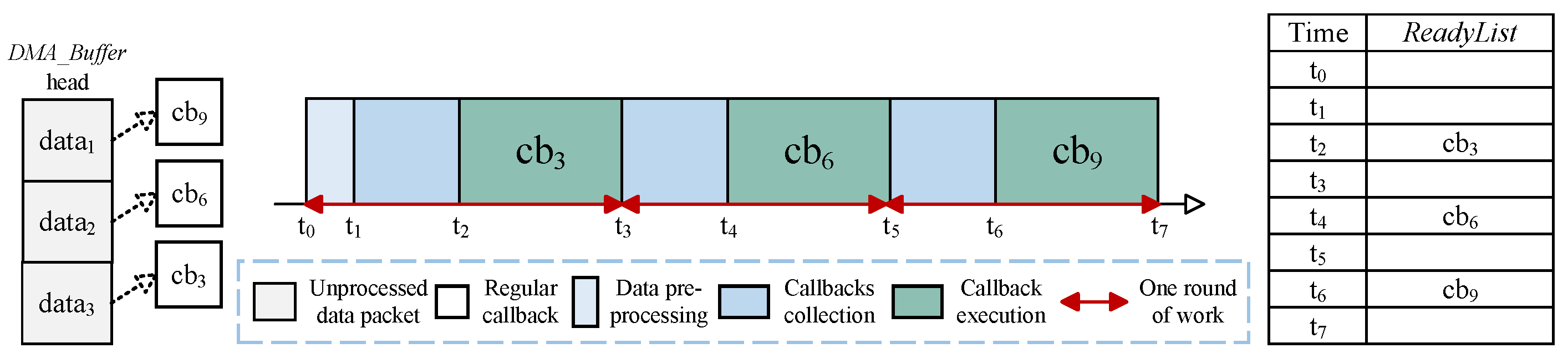
2.2. Callback Scheduling Model in Micro-ROS

The workflow of the default RCLC Executor in micro-ROS [14] is illustrated in Figure 2. During the initialization phase, an executor thread is typically created that is responsible for continuously executing the workflow of the RCLC Executor. The workflow of the RCLC Executor can be divided into two phases. In the collection phase, the executor thread first clears all callback points within w a i t _ s e t . The unique w a i t _ s e t is a critical component of the RCLC Executor, responsible for recording and managing ready callbacks. The executor thread traverses and checks all timer callbacks registered in micro-ROS, collecting all expired timer callbacks to the w a i t _ s e t . Subsequently, the executor thread processes the first unprocessed data packet received from the ROS 2 Agent and then collects the corresponding regular callback to w a i t _ s e t . During the execution phase, the executor thread checks whether the group of ready callbacks in w a i t _ s e t satisfies the trigger condition. If not satisfied, the executor thread proceeds to the next round of work. If satisfied, the executor thread executes all ready callbacks in w a i t _ s e t in order of the user-defined execution sequence.
Compared to the RCLCPP standard Executor in ROS 2, the RCLC Executor provides two new features: the trigger condition and the user-defined execution sequence [15]. The trigger condition determines when to start executing the group of ready callbacks. Within the RCLC Executor, there are four available trigger condition options, including ANY, ALL, ONE, and the user-defined function. The default trigger condition option is ANY, meaning that any ready callback can be executed if it exists. A reasonable configuration of trigger conditions can accomplish complex execution logic. For simplicity, we only analyze the ANY trigger condition option and omit a detailed discussion of the other three trigger condition options in this paper. The user-defined execution sequence implicitly assigns a priority to each callback. Within the same batch of ready callbacks, the ready callbacks registered earlier in micro-ROS will be executed first.

2.3. Communication Model between Micro-ROS and ROS 2 Agent

The data communication between micro-ROS and ROS 2 Agent can be divided into the following two modules: data transmission and data reception.

2.3.1. Data Transmission

Following each callback execution, micro-ROS may transmit data packets to the remote ROS 2 Agent. First, the executor thread serializes and frames the transmitted data packet according to the Stream Framing Protocol [11], copying it to the F r a m i n _ B u f f e r in the middleware layer. Micro XRCE-DDS supports two communication modes: best-effort and reliable. In the best-effort communication mode, the executor thread configures and enables the DMA transmission channel to transmit the data packet from F r a m i n g _ B u f f e r to the ROS 2 Agent. It should be noted that the executor thread and the DMA transmission channel work synchronously, requiring the executor thread to enter a self-blocking state to await the completion of DMA transmission channel operations. The difference between reliable and best-effort communication mode is that following the above steps, micro-ROS transmits a heartbeat message to the ROS 2 Agent. The ROS 2 Agent would respond with a corresponding acknowledgment message to micro-ROS, ensuring the normal connection between them. If the acknowledgment message indicates a failure in transmitting the previous data packet, the executor thread would retransmit this previous data packet. Both the heartbeat and acknowledgment messages have fixed and short lengths. While waiting for the acknowledgment message, the executor thread in micro-ROS also enters a self-blocking state.

2.3.2. Data Reception

In the current implementation, the reception and processing of data packets in micro-ROS are asynchronous. The DMA reception channel can automatically store received data packets in D M A _ B u f f e r without CPU involvement. During the collection phase, if the executor thread detects an unprocessed data packet in D M A _ B u f f e r , it performs the CRC verification to the payload of this data packet before copying it from D M A _ B u f f e r to S t a t i c _ B u f f e r _ M e m o r y . If there are multiple unprocessed data packets stored in the D M A _ B u f f e r , the executor thread adopts the FIFO (First-In-First-Out) strategy to process only one data packet. Therefore, the executor thread can collect, at most, one ready regular callback during each round of work.

3. Motivation

In this section, we discuss the performance issues present in the current micro-ROS design, with a specific focus on the limitations related to real-time capabilities.

3.1. Unpredictability in Callback Scheduling

As detailed in Section 2.2, micro-ROS utilizes a batch-based strategy to organize callback scheduling. In this approach, multiple ready callbacks are collected in w a i t _ s e t and then executed according to the user-defined priorities. This may potentially lead to priority inversion issues, resulting in less predictability of overall latency for a specific callback chain. We use the following example in Figure 3 to detail this problem.
There are three chains that bridge micro-ROS and ROS 2. The communication mode between micro-ROS and ROS 2 is used as the best effort. Each chain consists of one timer callback and two regular callbacks. The first and last callbacks are registered in micro-ROS, while the middle one is executed in ROS 2. The periods of three timer callbacks might be set equally, for example, the periods of c b 1 , c b 4 and c b 7 are all set to 100 ms or other values. The priority of callbacks within each chain increases with indices, indicating that the priority of c b 3 is higher than c b 1 . Conversely, the priority of chains decreases with indices, implying that the priority of c b 3 is higher than c b 9 . At t 0 , all three timer callbacks expire simultaneously and are collected in w a i t _ s e t at t 1 , then the executor thread executes those ready callbacks according to priorities. A message subscribed by c b 3 is received at t 4 , making c b 3 available for execution. However, the batch-based callback scheduling strategy requires the executor thread to finish executing c b 7 at t 9 before collecting c b 3 in w a i t _ s e t . Consequently, c b 3 cannot start to execute until t 11 , leading to a priority inversion problem.

3.2. Inefficiency and Unpredictability in Data Communication

3.2.1. Inefficiency in Data Transmission

In the current micro-ROS design, the executor thread sequentially manages callback execution and data transmission. As illustrated in Section 2.3.1, the data are copied to F r a m i n g _ B u f f e r after undergoing serialization and framing, after which the DMA transmission channel is configured and enabled to transmit the data to the remote ROS 2 Agent. Concurrently, the CPU enters a self-blocking state, implemented through busy waiting, to await the completion of data transmission. Obviously, this design can significantly reduce the runtime efficiency of micro-ROS and delay the execution of other ready callbacks, especially when publishers are transmitting large amounts of data. For example, as shown in Figure 3, following the execution of c b 1 , c b 4 and c b 7 , while micro-ROS is transmitting a large amount of data to the ROS 2 Agent, the executor thread enters a meaningless self-blocking state.

3.2.2. Unpredictability in Data Reception

Due to the lack of awareness of callback priority in the data-processing module, micro-ROS adopts the FIFO-based data-processing strategy to process data packets received from the ROS 2 Agent and stored in D M A _ B u f f e r . During each round of the collection phase, the executor thread processes only the first unprocessed data packet in D M A _ B u f f e r , leading to a priority inversion issue.
As illustrated in Figure 4, the periods of three timer callbacks in the example detailed in Figure 3 may be different, for example, the periods of c b 9 , c b 6 , and c b 3 are set to 100, 200, and 300 ms, respectively. In such a case, there might be three data packets corresponding to different regular callbacks in D M A _ B u f f e r at t 0 . For simplicity, the execution and data transmission of timer callbacks registered on micro-ROS are not considered temporarily. The executor thread processes only one data packet for each round of the collection phase according to the FIFO-based data-processing strategy. Therefore, c b 9 with the lowest priority is executed first, while c b 3 with the highest priority is executed last.

4. Overview

In this section, we first discuss the design challenges that must be overcome to enhance the capability of priority-driven chain-aware scheduling for micro-ROS, followed by an overview of our proposed PoDS framework.

4.1. Design Goals and Challenges

To improve run-time predictability. The above motivations demonstrate that priority inversion issues caused by both the batch-based callback scheduling strategy and FIFO-based data-processing strategy can impact the predictability of end-to-end latency for a specific chain. To solve priority inversion issues caused by the batch-based callback scheduling strategy, an intuitive approach is to update w a i t _ s e t after each ready callback completes its execution. However, the time cost associated with updating the w a i t _ s e t cannot be neglected, particularly when there are numerous callbacks registered in micro-ROS. Thus, we design an executor with two new structures to assist the executor thread in scheduling callbacks more efficiently. Additionally, this new design also incorporates a revised workflow to enable the executor thread to collect and execute ready callbacks in a more fine-grained manner. We name this executor with new structures and new workflow the Timing-Deterministic and Efficient (TIDE) Executor.
To solve priority inversion issues caused by the FIFO-based data-processing strategy, the simplest approach is to allow the executor thread to process all data packets currently stored in D M A _ B u f f e r during the collection phase of each work round. However, this approach fails to make the data-processing module aware of callback priority, introducing the time cost of processing unrelated data packets into the end-to-end latency of a specific chain, which still demonstrates unpredictability in data reception. To eliminate the interference of processing unrelated data packets and enhance the system’s run-time predictability, we design the priority-based data-processing mechanism.
To ensure run-time efficiency. To improve run-time efficiency, it is feasible to concurrently manage callback execution and data transmission. However, this simple parallel design cannot be compatible with the reliable communication mode, potentially leading to issues in scenarios where the publishers publish a substantial volume of data. In response to the above challenges, we design the Communication Daemon, which is specifically responsible for data management during communication between our PoDS and ROS 2 Agent. The Communication Daemon consists of two parts, enabling the system to efficiently transmit data to the ROS 2 Agent while also promptly processing received data packets, which can significantly enhance the system’s runtime efficiency.

4.2. PoDS Overview

As illustrated in Figure 5, we design and implement a priority-driven chain-aware scheduling system (PoDS) to improve the real-time performance of micro-ROS based on the existing micro-ROS architecture. First, we explicitly bind each callback with a priority. Regardless of callback scheduling, data transmission, or reception, the corresponding operations are carried out based on callback priorities. In our PoDS, the executor thread remains the central working entity, continuously running the workflow of the TIDE Executor to collect and execute callbacks in a more fine-grained manner. There are two chain-aware priority queues, named, respectively, T i m e r L i s t and R e a d y L i s t , within the TIDE Executor to assist the executor thread in scheduling callbacks as detailed in Section 5.1. During the processing of received data packets by the executor thread, the priority-based data-processing mechanism is used to prioritize the processing of data packets corresponding to high-priority callbacks, ensuring the predictability of end-to-end latency for specific chains as elaborated in Section 5.2. To ensure efficient and reliable communication, we introduce the Communication Daemon, which consists of two crucial modules. The parallel transmission handler enables parallel management of callback execution and data transmission, making data packets transmitted to the ROS 2 Agent based on their callback priorities as explained in Section 5.3.1. The interrupt-based data reception handler can manage regular messages and acknowledgment messages separately to support both best-effort and reliable communication modes as outlined in Section 5.3.2.

5. Design

In this section, we detail the design of three key components in our PoDS. The first is the TIDE executor responsible for callback scheduling, followed by the priority-based data-processing mechanism, and finally the Communication Daemon responsible for data management during the communication between the PoDS and ROS 2 Agent.

5.1. TIDE Executor

To solve priority inversion problems caused by the batch-based callback scheduling strategy, an intuitive approach is to update the w a i t _ s e t after each ready callback completes its execution. The time cost of updating w a i t _ s e t consists mainly of two parts: one involves clearing all callback pointers within w a i t _ s e t , and the other involves checking all timer callbacks to collect expired timer callbacks to w a i t _ s e t . When there are numerous callbacks registered in micro-ROS, the time cost associated with updating the w a i t _ s e t cannot be neglected, which can increase the end-to-end latency of chains. Additionally, since micro-ROS does not support binding each callback with a priority, it is inconvenient to find the ready callback with the highest priority in w a i t _ s e t . The executor thread needs to check all ready callbacks in w a i t _ s e t to find the ready callback with the highest priority, which also increases the end-to-end latency of chains. Therefore, to ensure the effective management of ready callbacks and eliminate the time cost of updating w a i t _ s e t , we design two new chain-aware priority queues, named, respectively, T i m e r L i s t and R e a d y L i s t , to replace w a i t _ s e t .
The T i m e r L i s t is used to monitor the status of all timer callbacks and is organized in increasing order according to the n e x t _ c a l l _ t i m e within each timer callback. The variable n e x t _ c a l l _ t i m e stores the next expiration time of the respective timer callback. During the collection phase of each round of work, the executor thread only needs to check whether the head callback of T i m e r L i s t has expired to determine if there are any expired timer callbacks in the system. Ready callbacks are inserted directly into R e a d y L i s t according to their priority configuration, so the ready callback with the highest priority always is the head callback of R e a d y L i s t .
Figure 6 illustrates the workflow of the TIDE Executor in each round of work. During the collection phase, the executor thread first determines the presence of expired timer callbacks in the system by checking whether the head callback of T i m e r L i s t has expired. If expired timer callbacks exist, they are collected to the R e a d y L i s t . Next, the executor thread determines whether there are unprocessed data packets in the system by checking D M A _ B u f f e r . If they are present, the executor thread utilizes the priority-based data-processing mechanism to process all unprocessed data packets currently in D M A _ B u f f e r , and subsequently, a regular callback with the highest priority is collected to the R e a d y L i s t . During the execution phase, the executor thread first determines whether the group of ready callbacks in R e a d y L i s t satisfies the trigger condition. If not satisfied, the executor thread skips the execution phase and proceeds to the next round of work. It should be noted that this paper adopts the default trigger condition ANY option for simplicity. This means that as long as there are ready callbacks in R e a d y L i s t , the default trigger condition ANY option is considered satisfied. Therefore, this paper effectively combines the determination of trigger condition satisfaction with the existence of ready callbacks in R e a d y L i s t . If ready callbacks exist, the executor thread takes the head callback of R e a d y L i s t out and executes it. After the callback execution, the system may require transmitting data packets to the ROS 2 Agent. To enhance run-time efficiency, PoDS employs the parallel transmission handler within the Communication Daemon to transmit data packets to the ROS 2 Agent.

5.2. Priority-Based Data-Processing Mechanism

After introducing our proposed TIDE Executor, the simplest approach to solve priority inversion issues caused by the FIFO-based data-processing strategy is allowing the executor thread to process all data packets currently stored in D M A _ B u f f e r during the collection phase of each round of work. As depicted in Figure 7, for convenience, we maintain the example in Figure 4 and temporarily exclude consideration of the execution and data transmission of timer callbacks registered in the system. In this approach, although c b 3 with the highest priority is executed first, the start execution time of c b 3 is delayed by the time cost of processing unrelated data packets d a t a 1 and d a t a 2 . This additional time cost is then added to the end-to-end latency of the chain containing c b 3 . The reason for this challenge is that while crucial data packet information, such as the length of data packet and the corresponding regular callback ID, is embedded in the data packet header, Micro XRCE-DDS only provides functions to process the entire data packet. The time cost of processing a complete data packet involves two primary parts: performing the CRC verification on the payload of this data packet, and copying it from D M A _ B u f f e r to S t a t i c _ B u f f e r _ M e m o r y . Therefore, the processing time cost is related to the length of the data packet. When dealing with large data packets, the processing time cost becomes a significant consideration that cannot be overlooked.
In our priority-based data-processing mechanism, we developed a new function based on Micro XRCE-DDS. This function solely parses the data packet header to obtain crucial data packet information, without involving CRC verification and payload copying operations. Since the size of the data packet header is fixed at approximately 20 bytes, the time cost of executing this new function is small and controllable. Before the executor thread performs formal data processing, it calls this new function to perform data preprocessing on all data packets currently stored in D M A _ B u f f e r to obtain their crucial information. Next, during the collection phase of each round of work, the executor thread collects a regular callback based on the priority corresponding to each data packet. As illustrated in Figure 8, after data preprocessing, the data-processing module becomes aware of the priorities corresponding to the three data packets currently stored in D M A _ b u f f e r . Subsequently, during the collection phase of each round of work, the executor thread collects and executes a regular callback based on their priorities. It should be noted that if preprocessed data packets are not immediately processed, their critical information is recorded and preserved for use in the next collection phase. This implies that each unprocessed data packet undergoes preprocessing only once. Moreover, because the interrupt-based data reception handler manages regular messages and acknowledgment messages separately, the priority-based data processing only needs to process regular messages.

5.3. Communication Daemon

The Communication Daemon is specifically responsible for data management during communication between PoDS and ROS 2 Agent, consisting of two crucial modules.

5.3.1. Parallel Transmission Handler

To improve run-time efficiency, it is feasible to concurrently manage callback execution and data transmission. However, this simple parallel design cannot be compatible with the reliable communication mode, which is considered the default option in micro-ROS. Furthermore, in scenarios where the publisher publishes a substantial volume of data, a potential problem may arise: the DMA transmission channel is occupied with data transmission from the previous round of work, while, simultaneously, the executor thread requests to use the DMA transmission channel for data transmission of the current round of work. This scenario presents a risk of data loss unless the CPU enters the busy waiting state to await the completion of data transmission from the previous round of work. When such data transmission conflicts occur frequently, the system’s run-time efficiency cannot be guaranteed too. We solve the above challenges by having the executor thread execute the parallel transmission handler.
Before introducing the parallel transmission handler, it is necessary to introduce the D a t a _ S e n d i n g _ P o o l . The D a t a _ S e n d i n g _ P o o l consists of three key components: D a t a _ P o o l , E x e c u t i o n _ B u f f e r , and P e n d i n g _ B u f f e r . The D a t a _ P o o l contains several pre-allocated buffer nodes. Each buffer node includes the data packet intended for transmission to the ROS 2 Agent, along with the communication mode, the callback priority, and the timestamp indicating when this node began its use. The buffer node that currently transmits the data is referred to as the C u r r e n t _ N o d e . Both the E x e c u t i o n _ B u f f e r and P e n d i n g _ B u f f e r are priority queues made up of buffer nodes. The E x e c u t i o n _ B u f f e r is sorted by callback priority in descending order, while the P e n d i n g _ B u f f e r is sorted by timestamp in ascending order.
As shown in Figure 9, the parallel transmission handler consists of two parts. During the execution phase, after the callback execution, when the system requires to transmit data packets to the ROS 2 Agent, the executor thread executes the first part of the parallel transmission handler after copying the serialized and framed data to the F r a m i n g _ B u f f e r . The parallel transmission handler begins by requesting an available buffer node from the D a t a _ P o o l , fills the data into this buffer node and adds it to the E x e c u t i o n _ B u f f e r based on the callback priority. If the DMA transmission channel is idle at this point, the parallel transmission handler takes out the head node of the E x e c u t i o n _ B u f f e r as the C u r r e n t _ N o d e , and configures and enables the DMA transmission channel to transmit the data packet within it to the ROS 2 Agent. If the DMA transmission channel is occupied at this time, the parallel transmission handler exits directly. If there are no available buffer nodes in the D a t a _ P o o l , the parallel transmission handler checks whether the head node of the P e n d i n g _ B u f f e r is expired. If it is, this node is reclaimed into the D a t a _ P o o l , and the CPU enters the busy waiting state to wait for the emergence of an available buffer node. Upon completion of the DMA transmission channel’s operation, the interrupt is automatically triggered to execute the second part of parallel transmission handler. Within the interrupt, the parallel transmission handler first checks the communication mode of the C u r r e n t _ N o d e . If the communication mode is the best effort, the C u r r e n t _ N o d e is reclaimed into the D a t a _ P o o l . If the communication mode is reliable, the C u r r e n t _ N o d e is added to the P e n d i n g _ B u f f e r based on its timestamp, and then a heartbeat message is sent to ensure normal connection between the PoDS and ROS 2 Agent. Subsequently, if the E x e c u t i o n _ B u f f e r remains nonempty, the head node of the E x e c u t i o n _ B u f f e r is taken out, and the data packet within it is transmitted to the ROS 2 Agent by configuring and enabling the DMA transmission channel.

5.3.2. Interrupt-Based Data Reception Handler

After introducing the parallel transmission handler, it is worth considering how to handle acknowledgment messages sent back to the ROS 2 Agent when the communication mode is reliable. As mentioned in Section 2.3.2, the micro-ROS lacks the capability to manage received data packets based on the message type. After micro-ROS transmits a heartbeat message to the ROS 2 Agent, the CPU falls into the self-blocking state to wait for the acknowledgment message reply. This sequential management evidently fails to ensure the system’s run-time efficiency. Therefore, we design and implement the interrupt-based data reception handler to separately manage regular messages and acknowledgment messages.
When receiving a complete data packet, the DMA reception channel automatically triggers an idle interrupt. Within this idle interrupt, the interrupt-based data reception handler first examines the type of received data packet. If it is a regular message, the interrupt-based data reception handler exits directly, postponing the processing of this regular message to the collection phase of the TIDE Executor. Acknowledgment messages, due to their fixed length and minimal processing time cost, can be efficiently processed within the idle interrupt. If the received acknowledgment message confirms the successful transmission of the previous data packet to the ROS 2 Agent, the corresponding node within the P e n d i n g _ B u f f e r is reclaimed into the D a t a _ P o o l . However, if the received acknowledgment message indicates a failure in transmitting the previous data packet to the ROS 2 Agent, the corresponding node within the P e n d i n g _ B u f f e r is added to the E x e c u t i o n _ B u f f e r according to its callback priority.

6. Evaluation

This section evaluates the real-time performance of our proposed PoDS by contrasting it with the micro-ROS. We start by outlining the experimental configuration, followed by conducting experiments with simulated parameters to investigate the performance attributes of both our proposed PoDS and the micro-ROS.

6.1. Environment Setup

Experimental platform. We implemented our proposed PoDS based on ROS 2 Humble of micro-ROS, running on the commonly used NUCLEO-F767ZI [16] microcontroller. This microcontroller features an ARM 32-bit Cortex-M7 processor with a maximum CPU frequency of 216 MHz, 2 MB Flash, 512 KB SRAM, and other specifications. We fixed the CPU clock at 216 MHz. The underlying RTOS we adopted is FreeRTOS with the latest version of V202212.00. Our PoDS remains compatible with micro-ROS, ensuring support for all types of RTOS that micro-ROS supports. The FreeRTOS system tick is set to 10 ns to offer a precise wall clock. The ROS 2 with the Humble version is deployed on a desktop PC running Ubuntu 20.04.6 LTS with 14 cores and 16 GB of DRAM. Communication between micro-ROS and ROS 2 is established through the UART port operating at 115,200 bps. During the experiments, neither the microprocessor nor the desktop PC runs other tasks.
Measurement Metric. We primarily evaluate the real-time performance of our proposed PoDS or micro-ROS in terms of end-to-end latency, which represents the time cost taken for a specific chain to complete. We measured the time taken from the start of the first callback execution to the completion of the last callback in the chain using the xTaskGetTickCount() function provided by FreeRTOS. The time cost associated with obtaining the current time using this function is so small on our platform that it can be overlooked.

6.2. Experimental Results

6.2.1. Basic Characteristics

To evaluate the real-time performance of our proposed PoDS, especially in terms of its ability to ensure timing determinism for high-priority chains, we identify three crucial elements that could influence the overall workload in the system. These elements include the number of chains present in the system, the data packet size transmitted from PoDS/micro-ROS to the ROS 2 Agent, and the callback execution time within each chain. In every sub-experiment, we modify one variable individually to maintain experiment control while keeping all other conditions constant. Each chain in the experiment consists of one timer callback and two regular callbacks. Importantly, the first and last callbacks are registered in PoDS/micro-ROS, while the middle one is executed in ROS 2. Furthermore, the priority of callbacks within each chain increases with their indices, whereas the priority of chains decreases with their indices. To focus on evaluating the performance of PoDS or micro-ROS, we set the execution time of the middle callback in each chain to zero, and the size of data packets transmitted by the middle callback is fixed at 10 bytes. For the underlying communication, we employ Micro XRCE-DDS, opting for the best-effort Quality of Service (QoS).
Influence of the number of chains. In this experiment, the number of chains registered in PoDS/micro-ROS ranges from 1 to 5, and the timer callback period of each chain is set to 500 ms. The data packet size transmitted from PoDS/micro-ROS to the ROS 2 Agent is fixed at 100 bytes. The execution time of callbacks registered in PoDS/micro-ROS is fixed at 10 ms. The maximum end-to-end latency observed for the highest-priority chain is depicted in Figure 10.
The results show that as the number of chains increases, the end-to-end latency of the highest-priority chain in PoDS remains relatively unchanged, while in micro-ROS, it consistently increases. The reason for this is that callbacks in the low-priority chains of micro-ROS interfere with the high-priority chains, whereas PoDS remains unaffected. For instance, when only one chain is registered, the end-to-end latency of this chain is identical in both PoDS and micro-ROS. However, when multiple chains are registered in micro-ROS, the batch-based callback scheduling strategy adopted by the RCLC Executor can cause priority inversion problems. In contrast, the TIDE Executor in PoDS does not experience these priority inversion issues, resulting in minimal changes in end-to-end latency for the highest-priority chain. Further analysis reveals that as the number of chains increases, the end-to-end latency of the highest-priority chain in micro-ROS increases approximately linearly. With the addition of each low-priority chain, the end-to-end latency of the highest-priority chain in micro-ROS increases by approximately 20 ms. This is due to the impact of the execution time and the data transmission time of timer callbacks in two lower-priority chains.
Influence of the data packet size. The data transmission time in PoDS/micro-ROS is closely related to the size of the transmitted data packet. Therefore, the impact of data transmission time on the real-time performance of PoDS/micro-ROS can be evaluated by varying the size of the transmitted data packet. Furthermore, we can roughly determine the byte range of the transmitted data packet by examining the generic robot-specific message types ( c o m m o n _ m s g s ) [17] widely used by ROS applications. For example, the NavSatFix Message exceeds 116 bytes, and the PoseWithCovariance Message greatly exceeds 288 bytes. In this experiment, the data packet size transmitted from PoDS/micro-ROS to the ROS 2 Agent ranges from 100 to 500 bytes. There are three chains registered in PoDS/micro-ROS, and the timer callback period of each chain is set to 500 ms. The execution time of callbacks registered in PoDS/micro-ROS is fixed at 5 ms. The maximum end-to-end latency observed for the highest-priority chain is depicted in Figure 11.
The results demonstrate that as the size of transmitted data packets increases, the end-to-end latency of the highest-priority chain in both PoDS and micro-ROS exhibits a linear growth trend. However, the growth rate of micro-ROS significantly exceeds that of PoDS. For every additional 100 bytes of data packets, the end-to-end latency of the highest-priority chain in PoDS increases by approximately 10 ms, precisely matching the time cost of transmitting the 100 bytes data packet to the ROS 2 Agent. This indicates that the higher-priority chain in PoDS remains unaffected by lower-priority chains. For data packets of the same size, the end-to-end latency of the highest-priority chain in micro-ROS exceeds that of PoDS. This excess is equivalent to the sum of the execution time of timer callbacks and the data transmission time in two low-priority chains. Overall, as the size of data packets increases, the end-to-end latency of the highest-priority chain in PoDS is solely affected by its own data transmission time, while that of micro-ROS is influenced by the data transmission times of all three chains.
Influence of the callback execution time. In this experiment, the execution time of callbacks registered in PoDS/micro-ROS ranges from 10 to 50 ms. There are three chains registered in PoDS/micro-ROS, and the timer callback period of each chain is set to 500 ms. The data packet size transmitted from PoDS/micro-ROS to the ROS 2 Agent is fixed at 100 bytes. The maximum end-to-end latency observed for the highest-priority chain is depicted in Figure 12.
The results indicate that the end-to-end latency of the highest-priority chain in micro-ROS surpasses that of PoDS when the callback execution time is identical. Moreover, as the callback execution time increases, the latency gap between micro-ROS and PoDS progressively widens. Typically, the end-to-end latency of a chain comprises two callback execution times and one data transmission time. However, in PoDS, the executor thread can parallelly manage callback execution and data transmission due to the parallel transmission handler. For 50 bytes data packets, the data transmission time of approximately 7 ms is lower than the callback execution time of 10 ms. This shorter transmission time is masked by the execution time of timer callbacks, resulting in the end-to-end latency of the highest-priority chain being represented by the sum of three callback execution times. In contrast, the batch-based callback scheduling strategy employed by the RCLC Executor in micro-ROS results in the end-to-end latency of the highest-priority chain comprising the sum of four callback execution times and three data transmission times. Upon examination, when the callback execution time is equivalent, the excess portion of the end-to-end latency on micro-ROS, compared to PoDS, precisely aligns with one callback execution time and three data transmission times.

6.2.2. Performance under Reliable Communication

The goal of this experiment is to evaluate the real-time performance of PoDS compared to that of micro-ROS in the reliable communication mode. In this experiment, there are three chains registered in PoDS/micro-ROS, each containing three callbacks: a timer callback and two regular callbacks. While the middle callback is executed using ROS 2, the first and last callbacks are handled by PoDS/micro-ROS. The timer callback period of each chain is set to 500 ms. The size of data packets transmitted from PoDS/micro-ROS to the ROS 2 Agent is fixed at 100 bytes. The execution time of callbacks registered in PoDS/micro-ROS is fixed at 10 ms. To focus on evaluating the performance of PoDS or micro-ROS, the execution time of the middle callback in each chain is set to zero, with the size of data packets transmitted by the middle callback fixed at 10 bytes. For the underlying communication, Micro XRCE-DDS is employed, utilizing the reliable Quality of Service (QoS).
In this experiment, we measure the end-to-end latency of the highest-priority chain 500 times. Throughout the experiment, we intercept the acknowledgment messages sent back from the ROS 2 Agent and customized their parsing content. In certain cases, the acknowledgment messages indicate that the first data transmission from PoDS/micro-ROS to ROS 2 Agent is considered successful. On the contrary, in the remaining cases, the acknowledgment messages indicate that the first data transmission failed. At this time, PoDS or micro-ROS is required to retransmit the previous data packet to the ROS 2 Agent, with the second data transmission guaranteed to be successful. We define the ratio of the number of first successful transmissions to the total number as the successful probability. The end-to-end latency observed for the highest-priority chain 500 times varies with the successful probability as depicted in Figure 13.
The results show that when the successful probability is equal, the end-to-end latency of the highest-priority chain in micro-ROS consistently exceeds that of PoDS as detailed in the preceding section. As the successful probability increases, the average end-to-end latency of the highest-priority chain in both micro-ROS and PoDS shows a decreasing trend. However, the difference in end-to-end latency between the successful probability of 0% and 100% for the highest priority chain in micro-ROS is approximately three times that of PoDS. This is because, in the event of the first data transmission failure, the end-to-end latency of the highest-priority chain on PoDS only includes the second data transmission time within the same chain. In contrast, the end-to-end latency of the highest-priority chain in micro-ROS includes the second data transmission time not only within the same chain but also within the two lower-priority chains. This demonstrates that, under reliable communication mode, the timing determinism of the end-to-end latency for the high-priority chain in PoDS remains significantly higher than that of micro-ROS. A more detailed numerical comparison is presented in Table 1, which includes the minimum (MIN), average (AVE), maximum (MAX), and standard deviation (STD) values of the end-to-end latency of the highest-priority chain in each group. We can observe that the STD value of the micro-ROS with different successful probability rates is significantly higher than that of PoDS, which indicates that our PoDS demonstrates a more stable real-time performance compared to micro-ROS.

7. Related Work

Significant research efforts have been directed towards improving real-time performance in ROS [18,19,20]. For example, a real-time ROS architecture for multi-core processors is introduced in [18] and a real-time scheduling framework for ROS is introduced in [21]. However, these studies are applicable only to early versions of ROS and lack analytical methods to ensure real-time timing constraints.
Since the release of ROS 2 in 2017, numerous studies have been conducted aimed at improving or evaluating its real-time performance. For example, ref. [22] presented the first formal analysis and modeling of ROS 2 to bound the end-to-end latency of ROS 2 applications. Subsequent work [23] further improved the response time bound for the default ROS 2 executor. The ROS 2 employs two types of executors internally: the single-threaded executor and the multi-threaded executor. Tang et al. in [24] conducted a response time analysis of the single-threaded executor through formal modeling. Jiang et al. in [25] focused on real-time scheduling and analysis under the multi-threaded executor in their work. Furthermore, in recent research conducted by Choi et al. [26,27], novel chain-level priority-based scheduling schemes were proposed for the ROS 2 executor with the objective of improving real-time performance. Liu et al. in [28] proposed a new multi-threaded executor called RTeX for ROS 2 to improve system performance in terms of both run-time efficiency and timing predictability.
Although micro-ROS is a variant of ROS 2 focused on putting ROS 2 onto resource-constrained microcontrollers, research on micro-ROS is currently limited. The official website of micro-ROS [5] only provides tutorials on how to use micro-ROS, without offering a comprehensive exploration of its internal mechanisms or comparative evaluations with other embedded real-time systems. In [29], an advanced budget-based real-time executor with multithreading support was introduced but failed to explore or discuss the limitations of the default RLCL Executor in micro-ROS. Recent works such as [30,31] are dedicated to exploring the practical application development of micro-ROS in real-world scenarios. Meanwhile, Peter et al. [32] strove to conduct the modeling and timing analysis of micro-ROS applications, while their ultimate objective being the implementation of micro-ROS on alternative platforms.
Besides micro-ROS, mROS [33] also integrates resource-constrained microcontrollers with classic ROS. It provides a basic implementation of core ROS concepts on embedded devices, allowing for the creation of multiple ROS nodes on the same microcontroller. The mROS features an efficient shared memory communication mechanism for message exchange between nodes on the same microcontroller, and utilizes the lightweight TCP/IP stack lwIP [34] for data communication between remote ROS nodes. Recently, mROS 2 [35] was published to offer a basic implementation of the fundamental concepts of ROS 2 directly on the embedded device. EmbeddedRTPS [36,37] and Data Distribution Service (DDS) are used in mROS 2 to achieve efficient communication between remote nodes, but its scalability remains to be improved.

8. Conclusions and Future Work

In this paper, we identify three crucial issues stemming from unreasonable designs within micro-ROS after conducting in-depth research on its callback scheduling and communication models. To improve the timing predictability and run-time efficiency of micro-ROS, we design and implement a priority-driven chain-aware scheduling system (PoDS) based on the existing micro-ROS architecture, which consists primarily of the following three components. The TIDE Executor makes the collection and execution of ready callbacks more fine-grained, and the priority-based data-processing mechanism enables the data-processing module to recognize callback priorities. They effectively resolve priority inversion issues present in micro-ROS. The Communication Daemon can ensure the communication efficiency of PoDS and ROS 2 Agent in multiple communication modes. Through a comprehensive series of experiments, our proposed PoDS demonstrates superior and more stable real-time performance compared to the default micro-ROS.
The PoDS is developed on the existing micro-ROS framework, where the ROS 2 Agent significantly affects the real-time performance of micro-ROS or PoDS. The mROS 2 achieves an agentless and lightweight runtime environment for embedded devices using embeddedRTPS. In the future, we hope to overcome the limitations of the ROS 2 Agent by introducing the concept of embeddedRTPS design within the PoDS framework.

Author Contributions

Methodology, S.L., D.J. and W.Y.; Software, Z.W. All authors have read and agreed to the published version of the manuscript.

Funding

This research was funded by NSFC Project under Grant 62302083 and in part by Liaoning Provincial United Natural Science Foundation (2023BSBA-123) and in part by the Fundamental Research Funds for the Central Universities (N2316009).

Data Availability Statement

Data are contained within the article.

Conflicts of Interest

The authors declare no conflicts of interest.

References

  1. ROS Introduction. Available online: http://wiki.ros.org/ROS/Introduction/ (accessed on 24 March 2024).
  2. ROS Robots. Available online: https://robots.ros.org/ (accessed on 8 February 2024).
  3. Macenski, S.; Foote, T.; Gerkey, B.; Lalancette, C.; Woodall, W. Robot Operating System 2: Design, architecture, and uses in the wild. Sci. Robot. 2022, 7, eabm6074. [Google Scholar] [CrossRef] [PubMed]
  4. Belsare, K.; Rodriguez, A.C.; Sánchez, P.G.; Hierro, J.; Kołcon, T.; Lange, R.; Lütkebohle, I.; Malki, A.; Losa, J.M.; Melendez, F.; et al. Micro-ros. In Robot Operating System (ROS) The Complete Reference; Springer International Publishing: Cham, Switzerland, 2023; Volume 7, pp. 3–55. [Google Scholar]
  5. micro-ROS Puts ROS 2 on Microcontrollers. Available online: https://micro.ros.org/ (accessed on 13 February 2024).
  6. Li, B.; Ma, Z.; Zhao, Y. 2D Mapping of Mobile Robot Based on micro-ROS. In Proceedings of the 2022 4th International Symposium on Robotics & Intelligent Manufacturing Technology (ISRIMT 2022), Online, 23–25 September 2022; IOP Publishing: Bristol, UK, 2022; Volume 2402, p. 012030. [Google Scholar]
  7. Features and Architecture. Available online: https://micro.ros.org/docs/overview/features/ (accessed on 13 February 2024).
  8. Barry, R. FreeRTOS. Internet, Oct. 2008. Available online: https://www.freertos.org/RTOS.html (accessed on 1 January 1980).
  9. The Zephyr Project. Available online: https://www.zephyrproject.org/ (accessed on 24 March 2024).
  10. Apache NuttX. Available online: https://nuttx.apache.org/ (accessed on 21 February 2024).
  11. eProsima Micro XRCE-DDS. Available online: https://micro-xrce-dds.docs.eprosima.com/en/latest/ (accessed on 30 March 2024).
  12. Micro XRCE-DDS. Available online: https://micro.ros.org/docs/concepts/middleware/Micro_XRCE-DDS/ (accessed on 13 February 2024).
  13. Micro XRCE-DDS Memory Profiling. Available online: https://micro.ros.org/docs/concepts/middleware/memo_prof/ (accessed on 13 February 2024).
  14. Staschulat, J.; Lütkebohle, I.; Lange, R. The rclc executor: Domain-specific deterministic scheduling mechanisms for ros applications on microcontrollers: Work-in-progress. In Proceedings of the 2020 International Conference on Embedded Software (EMSOFT), Shanghai, China, 20–25 September 2020; pp. 18–19. [Google Scholar]
  15. rclc Executor. Available online: https://micro.ros.org/docs/concepts/client_library/execution_management/#rclc-executor (accessed on 13 February 2024).
  16. NUCLEO-F767ZI. Available online: https://www.st.com/en/evaluation-tools/nucleo-f767zi.html (accessed on 5 April 2024).
  17. common_msgs—ROS Wiki. Available online: https://wiki.ros.org/common_msgs (accessed on 21 April 2024).
  18. Wei, H.; Shao, Z.; Huang, Z.; Chen, R.; Guan, Y.; Tan, J.; Shao, Z. RT-ROS: A real-time ROS architecture on multi-core processors. Future Gener. Comput. Syst. 2016, 56, 171–178. [Google Scholar] [CrossRef]
  19. Saito, Y.; Sato, F.; Azumi, T.; Kato, S.; Nishio, N. Rosch: Real-time scheduling framework for ros. In Proceedings of the 2018 IEEE 24th International Conference on Embedded and Real-Time Computing Systems and Applications (RTCSA), Hakodate, Japan, 28–31 August 2018; pp. 52–58. [Google Scholar]
  20. Suzuki, Y.; Azumi, T.; Kato, S.; Nishio, N. Real-time ros extension on transparent cpu/gpu coordination mechanism. In Proceedings of the 2018 IEEE 21st International Symposium on Real-Time Distributed Computing (ISORC), Singapore, 29–31 May 2018; pp. 184–192. [Google Scholar]
  21. Saito, Y.; Azumi, T.; Kato, S.; Nishio, N. Priority and synchronization support for ROS. In Proceedings of the 2016 IEEE 4th International Conference on Cyber-Physical Systems, Networks, and Applications (CPSNA), Nagoya, Japan, 6–7 October 2016; pp. 77–82. [Google Scholar]
  22. Casini, D.; Blaß, T.; Lütkebohle, I.; Brandenburg, B. Response-time analysis of ROS 2 processing chains under reservation-based scheduling. In Proceedings of the 31st Euromicro Conference on Real-Time Systems, Stuttgart, Germany, 9–12 July 2019; pp. 1–23. [Google Scholar]
  23. Blaß, T.; Casini, D.; Bozhko, S.; Brandenburg, B.B. A ROS 2 response-time analysis exploiting starvation freedom and execution-time variance. In Proceedings of the 2021 IEEE Real-Time Systems Symposium (RTSS), Dortmund, Germany, 7–10 December 2021; pp. 41–53. [Google Scholar]
  24. Tang, Y.; Feng, Z.; Guan, N.; Jiang, X.; Lv, M.; Deng, Q.; Yi, W. Response time analysis and priority assignment of processing chains on ros2 executors. In Proceedings of the 2020 IEEE Real-Time Systems Symposium (RTSS), Houston, TX, USA, 1–4 December 2020; pp. 231–243. [Google Scholar]
  25. Jiang, X.; Ji, D.; Guan, N.; Li, R.; Tang, Y.; Wang, Y. Real-time scheduling and analysis of processing chains on multi-threaded executor in ros 2. In Proceedings of the 2022 IEEE Real-Time Systems Symposium (RTSS), Houston, TX, USA, 5–8 December 2022; pp. 27–39. [Google Scholar]
  26. Choi, H.; Xiang, Y.; Kim, H. PiCAS: New design of priority-driven chain-aware scheduling for ROS2. In Proceedings of the 2021 IEEE 27th Real-Time and Embedded Technology and Applications Symposium (RTAS), Nashville, TN, USA, 18–21 May 2021; pp. 251–263. [Google Scholar]
  27. Sobhani, H.; Choi, H.; Kim, H. Timing Analysis and Priority-driven Enhancements of ROS 2 Multi-threaded Executors. In Proceedings of the 2023 IEEE 29th Real-Time and Embedded Technology and Applications Symposium (RTAS), San Antonio, TX, USA, 9–12 May 2023; pp. 106–118. [Google Scholar]
  28. Liu, S.; Jiang, X.; Guan, N.; Wang, Z.; Yu, M.; Yi, W. RTeX: An Efficient and Timing-Predictable Multi-threaded Executor for ROS 2. IEEE Trans. Comput.-Aided Des. Integr. Circuits Syst. 2024; Early Access. [Google Scholar]
  29. Staschulat, J.; Lange, R.; Dasari, D.N. Budget-based real-time executor for micro-ROS. arXiv 2021, arXiv:2105.05590. [Google Scholar]
  30. Bappanadu, S.R. Modeling and Timing Analysis of Micro-ROS Application on an Off-Road Vehicle Control Unit. Master’s Thesis, University of Stuttgart, Stuttgart, Germany, 2022. [Google Scholar]
  31. Mudalige, N.D.; Zhura, I.; Babataev, I.; Nazarova, E.; Fedoseev, A.; Tsetserukou, D. Hyperdog: An open-source quadruped robot platform based on ros2 and micro-ros. In Proceedings of the 2022 IEEE International Conference on Systems, Man, and Cybernetics (SMC), Prague, Czech Republic, 9–12 October 2022; pp. 436–441. [Google Scholar]
  32. Nguyen, P. Micro-Ros for Mobile Robotics Systems. 2022. Available online: https://mdh.diva-portal.org/smash/record.jsf?pid=diva2%3A1670378&dswid=7005 (accessed on 23 April 2024).
  33. Takase, H.; Mori, T.; Takagi, K.; Takagi, N. mROS: A lightweight runtime environment for robot software components onto embedded devices. In Proceedings of the 10th International Symposium on Highly-Efficient Accelerators and Reconfigurable Technologies, Nagasaki, Japan, 6–7 June 2019; pp. 1–6. [Google Scholar]
  34. lwIP—A Lightweight TCP/IP Stack—Summary. Available online: https://savannah.nongnu.org/projects/lwip/ (accessed on 19 April 2024).
  35. mROS 2. Available online: https://github.com/mROS-base/mros2 (accessed on 19 April 2024).
  36. Kampmann, A.; Wüstenberg, A.; Alrifaee, B.; Kowalewski, S. A portable implementation of the real-time publish-subscribe protocol for microcontrollers in distributed robotic applications. In Proceedings of the 2019 IEEE intelligent transportation systems conference (ITSC), Auckland, New Zealand, 27–30 October 2019; pp. 443–448. [Google Scholar]
  37. embeddedRTPS. Available online: https://github.com/embedded-software-laboratory/embeddedRTPS (accessed on 19 April 2024).
Figure 1. Micro-ROS architecture.
Electronics 13 01658 g001
Figure 2. The workflow of RCLC Executor.
Electronics 13 01658 g002
Figure 3. Priority inversion caused by batch-based callback scheduling strategy.
Electronics 13 01658 g003
Figure 4. Priority inversion caused by FIFO-based data-processing strategy.
Electronics 13 01658 g004
Figure 5. PoDS architecture.
Electronics 13 01658 g005
Figure 6. The workflow of TIDE Executor.
Electronics 13 01658 g006
Figure 7. Process all data packets currently stored in D M A _ B u f f e r .
Electronics 13 01658 g007
Figure 8. Priority-based data-processing mechanism.
Electronics 13 01658 g008
Figure 9. The workflow of the parallel transmission handler.
Electronics 13 01658 g009
Figure 10. Influence of the number of chains on maximum end-to-end latency.
Electronics 13 01658 g010
Figure 11. Influence of transmitted data packet size on maximum end-to-end latency.
Electronics 13 01658 g011
Figure 12. Influence of callback execution time on maximum end-to-end latency.
Electronics 13 01658 g012
Figure 13. Influence of successful probability on end-to-end latency under reliable communication.
Electronics 13 01658 g013
Table 1. Performance comparison under reliable communication.
Successful Probability020%40%60%80%100%
micro-ROS
[ms]
MIN114.2784.1184.3484.3484.0184.16
AVE115.09107.44102.9696.8791.1585.03
MAX115.96115.81116.19116.54115.7885.80
STD0.3410.7910.7314.7012.030.33
PoDS
[ms]
MIN48.3140.9440.9440.9440.9441.06
AVE48.9747.0445.5943.9742.4841.07
MAX49.7049.4249.9549.7749.6741.09
STD0.303.103.843.713.100.01
Disclaimer/Publisher’s Note: The statements, opinions and data contained in all publications are solely those of the individual author(s) and contributor(s) and not of MDPI and/or the editor(s). MDPI and/or the editor(s) disclaim responsibility for any injury to people or property resulting from any ideas, methods, instructions or products referred to in the content.

