1. Introduction
Historically, the commercial satellite communications (SatCom) sector has been dominated by geosynchronous orbits (GSOs), especially geostationary orbits (GEOs) [
1]. However, in recent years the use of non-geosynchronous orbits (NGSOs) has been a steadily growing feature of the industry [
2]. GSO and NGSO systems have been typically designed in isolation, serving different markets and customers. Both systems have their own strengths. GSO systems can offer broad contiguous service regions, fixed ground antenna orientations, longer satellite lifetimes, a simpler frequency coordination environment, lower financial costs to achieve regional coverage, and lower maintenance/operational costs. On the other hand, NGSO systems, such as low Earth orbit (LEO) constellations, can offer improved latency, significantly reduced path losses enabling miniaturization of ground terminals, have the potential to provide truly global coverage also including the polar areas, and support the maximum total system capacity within a given spectrum allocation.
Future SatCom system topologies should benefit a range of diverse space elements, integrating together GEO, LEO, or medium Earth orbit (MEO) satellites [
3]. This leads to the multi-layered SatCom system (MLSS) architecture studied previously, e.g., between LEO and MEO systems in [
4,
5]. The MLSS definition we adopt is that of a satellite communication network that aggregates multiple satellite layers, where different layers refer to different orbiting altitudes of satellite constellations and that has been thoroughly designed to operate as a multi-layer system, rather than a loose aggregation of different layers. Consequently, we make an assumption that an MLSS is expected to have at least two satellite orbital layers in addition to potentially any other terrestrial layers.
Such a system should be capable of supporting the full range of both current and future satellite service types, but with increased overall spectral efficiency and interoperability with aerial platforms, such as high-altitude platforms (HAPSs) and unmanned aerial vehicles (UAVs), and terrestrial networks. There have been numerous papers published in recent years proposing three-dimensional (3D) satellite-terrestrial network architectures [
6,
7,
8]. Those papers have covered topics such as human-centric application areas and high-security requirements [
6], the role of 5G non-terrestrial networking (NTN) to support 6G requirements [
7,
8], and the role of satellite communications to support remote areas and sustainable development [
8]. The findings reported in these papers have pointed out the importance of LEO satellite systems but also that the role of satellites in higher orbits remains important for resilience [
9,
10]. Integration of UAV networks and satellites has been studied in [
11,
12,
13], which covered local capacity enhancements, interference management, and trajectory optimizations.
However, a detailed analysis of modern MLSS systems covering technical enablers, economic factors, and the current regulatory landscape is missing in the literature. While several review papers consider conceptually the full space-aerial-terrestrial integrated network, the authors pay less attention to the important MLSS part of the overall network. Therefore, in this paper, we will first conduct a market analysis to present the most potential application areas. Through technology research, we then aim to answer the following research questions:
How does the introduction of multiple satellite layers benefit and challenge future SatCom system architecture?
What are the main enablers for more optimized coordination of different layers in future MLSS systems?
To answer those questions, one must consider the whole network topology and space segment design, as well as access protocols, routing, network operations, inter-satellite link (ISL) technologies, and ground antenna technologies. The novelty of this paper is four-fold:
We provide a thorough assessment of multi-layered satellite systems covering markets, regulations, and technology enablers.
We define the MLSS concept and the system architecture enabling ultra-high availability and resilience both for commercial and governmental users.
We have implemented a simulation model and testbed and show with the initial results the achievable performance with implemented routing policies.
Finally, we define potential future research directions, taking into account the validation results obtained from our testbed work.
This paper is structured as follows:
Section 2 provides an analysis of markets and regulatory factors affecting the use and adoption of MLSS systems.
Section 3 is the technology analysis, describing what kind of benefits and challenges there are. The system model is presented in
Section 4, and selected results from our simulations and testbed work in
Section 5. Future research directions are identified in
Section 6, and this paper is concluded in
Section 7.
2. Market Analysis and Regulations
2.1. Market Analysis: Significant Growth Expected
Multiple published forecasts predict significant growth for the SatCom industry. The global satellite communication market size was valued at USD 66.63 billion in 2020 and was predicted in [
14] to expand at a compound annual growth rate (CAGR) of 13%. According to [
15], the global 5G NTN market was valued at USD 3.2 billion in 2022 and is projected to reach USD 93.6 billion by 2032, growing at a CAGR of 40.6% from 2023 to 2032. Finally, Morgan Stanley predicts in [
16] that the whole space economy will grow to USD 1000 billion by 2040 and at that time consumer broadband services and internet access over satellites will be a market worth over USD 500 billion. The drivers behind this growth are mainly the ever-increasing bandwidth capability, lower latency, higher reliability, and extension of terrestrial 5G/6G into otherwise hard-to-reach areas. The capacity demand and revenue in high throughput satellites, as well as in all verticals (commercial aviation, maritime, land and IoT, military and defense, civil government and public sector, and consumer/mass market) will increase during the next decade significantly.
The growth is very well seen in the number of LEO satellites launched annually into space. In the year 2022 alone, almost 2000 SatCom satellites were launched, and this growth is predicted to continue due to constellation plans from the USA, China, and Europe, including the European Union’s multi-layer satellite system plan, called Infrastructure for Resilience, Interconnectivity and Security by Satellite (IRIS
2), that is planned to be ready in 2027. At the same time, High Throughput Satellite (HTS) demand is projected to expand nine-fold during this decade, from ~1.6 Tbps in 2021 to 14.7 Tbps in 2030, divided roughly in half between GEO and NGSO capacity [
17]. GEO capacity accounts for most revenues, but NGSO is expected to see the fastest growth during the forecast period.
Satellite communication has, until recently, been largely a unique technology, independent of terrestrial mobile networking, this situation is highly likely to change. Combining satellites with 5G infrastructure can enhance the quality of experience (QoE) of many different applications. Having cooperated terrestrial and non-terrestrial systems can save valuable spectrum and improve each network’s resilience by, for example, intelligent routing and traffic offloading. Satellite systems will play a crucial part in extending terrestrial 5G/6G networks to land, sea, air, and other hard-to-reach, remote and rural areas of the planet traditionally beyond the reach of the terrestrial network’s coverage area. Satellite systems could extend 5G services from the city to airplanes, cruise liners, and other vehicles in remote locations. Internet of Things (IoT) sensors and machine-to-machine (M2M) connections on farms and remote worksites like mines can also benefit from the broad coverage areas offered by 5G capable satellite systems.
The extension of the 3GPP standards to the non-terrestrial networks facilitates the integration of the terrestrial and non-terrestrial networks. The possibility of tight integration of the terrestrial and non-terrestrial networks offers a unique opportunity for the satellite industry to expand its ecosystem by establishing itself in the global communications ecosystem and to benefit from a significant market renewal. To evolve toward tightly integrated terrestrial and non-terrestrial communication networks and to unlock the vast addressable market segments, satellite operators should embrace open standards and move away from the proprietary models currently widely used in the satellite industry. The 3GPP 5G New Radio non-terrestrial radio interface allows direct connectivity to the non-terrestrial networks. In this way, a standard mobile device can connect to the terrestrial infrastructure or communicate with the satellite without any modification. This opens the door for the satellite industry to participate in the mainstream production and distribution ecosystem [
18]. By adopting the 5G unified core network framework, the satellite system will become seamlessly integrable with other communication service provider systems, e.g., terrestrial mobile communication systems or other satellite communication systems. Moreover, with the adoption of the 5G core network, satellite systems can leverage technologies developed in the 5G ecosystem to increase the system’s flexibility and optimize its operation.
The application areas where MLSS satellite systems are seen as especially useful are ones requiring ultra-high availability and resilience, including industrial systems, military users, and mission-critical communications in remote areas. The multi-layer architecture can provide decent connectivity even when the LEO layer is targeted by malicious users by means of jamming or anti-satellite weapons.
2.2. Regulatory Factors for MLSS Systems
Regulations are needed to ensure that different systems can operate at their designated frequencies and to enable sustainable operations in the future. They provide an international framework to be followed by space nations—and ways to control and monitor the actual operations. In general, regulations cover many social, economic, and environmental topics such as territorial aspects, frequency management, and space safety. Regulations include spectrum regulation (International Telecommunications Union Radiocommunication Sector (ITU-R), regional, and country-specific regulations and authorities, licensing, and spectrum access rules), environmental regulations, and industrial standards. Spectrum regulations are needed to ensure the operations of planned MLSS systems, and these need to be defined first at the international level by ITU-R and later refined and implemented by regional and national administrations.
The regulatory factors of MLSS spectrum use cover intersatellite links (ISLs), feeder links, and user links. Many topics were covered in the World Radio Conference 2023 (WRC-23) that was held in Dubai on 20 November–15 December 2023. For example, agenda item 1.17 was dedicated to determining “appropriate regulatory actions for the provision of inter-satellite links in specific frequency bands, or portions thereof, by adding an inter-satellite service allocation where appropriate”. Suitable frequency bands and interference rules need to be determined for the links as well as for frequency sharing between GSO and NGSO satellite systems—and between satellite systems and terrestrial networks potentially coexisting in the bands where 5G NTN technology is used. Let us summarize the regulatory factors for each segment of the MLSS system.
Intersatellite links: ISL links can be implemented either using radio frequency (RF) or optical technology. There are no standards defined for ISL links currently and no regulations for optical technology in space. Regarding the RF links, the ITU-R radio regulations [
19] specify certain frequency bands for inter-satellite services as primary services: the K-band, the Ka-band, and the mm bands. Additionally, the footnotes of [
19] indicate other bands allocated to other primary services that can also be used for the space-to-space direction, in the UHF, L-band, S-band, and C-band. Fixed-satellite service (FSS) connections also include, in some cases, satellite-to-satellite links, but this is not specified in the allocation tables. One solution is to use the bands allocated to industrial, scientific, and medical (ISM) applications [
20]. The ISM band that corresponds to a fixed-satellite service is the 5.725–5.875 GHz.
Feeder links are categorized as FSS links. The footnotes in Article 5 of [
19] indicate for which kind of services the FSS can be used in each frequency band, whether the FSS link is for GSO or NGSO satellites, and whether the link can be used as a feeder link to broadcasting (BSS), mobile (MSS), or fixed satellite systems. Hence, deciding which band is appropriate requires knowing the satellite’s orbit and the service that the satellite is providing to the users of that service. Article 22 in [
19] includes Equivalent Power Flux Density (EPFD) limits radiated by space stations and Earth stations of NGSO systems in FSS in certain frequency bands.
User links: Depending on the scenario, those links can be MSS, FSS, BSS, or Earth Exploration Satellite Service (EESS). It is more important to check the most appropriate standards for those links than the ITU-R regulations. They specify all the requirements both ends of the system must comply with. For example, the 3GPP has guidelines for extraterritorial 5G systems [
21].
GSO-
NGSO coexistence in the same band: To minimize the terminal costs, a solution in which the terminal can be connected to both GSO and NGSO would be necessary. In the ITU-R RR [
19], GSO and NGSO are usually seen as competing for resources, hence, either the bands are limited to only a certain orbit, or EPFD hard limits and coordination are used to protect GSO links. The main technical solution is for the NGSO to avoid operating when it is interfering with a GSO. Additional considerations and aspects needing further consideration have been listed in [
22]. The main issues are regarding the coexistence of GSO and NGSO and the interference created by a large constellation of NGSOs upon GSO systems or other NGSO systems. It is not yet settled how the limits should be set and a lot of work is ongoing to calculate and monitor this interference and how to mitigate it. However, the scenario in which both NGSO and GSO belong to the same network does not seem to be considered in the regulations or the ongoing activities. If a band is allocated to both GSO and NGSO and both satellite layers follow the hard limits imposed in Article 22 [
19], there is no reason to not allow them to coexist, even more so if they are part of the same network.
Satellite-
terrestrial coexistence: One potential way to share the band is between the terrestrial network (TN) and the non-terrestrial network that is under the control of the same core network, and the terminal could then connect either to a terrestrial base station or the gNB in the orbit. Spectrum sharing between satellite and terrestrial systems in a coexisting manner where the systems are separate (not under the same core) requires information exchange since spectrum sensing-based solutions cannot guarantee interference-free operations. Controlled sharing can be potentially enabled by database-assisted sharing where a third-party entity is giving rights to the lower priority sharing party with a given frequency and power allocation. For example, the licensed shared access (LSA) system studied in [
23] has been implemented and shown to be able to control a scalable number of users and their resource allocations in such a way that interference at the primary user reception can be controlled.
In the 3GPP domain, the spectrum is divided into two frequency ranges (FRs), where FR1 covers frequencies below 6 GHz and FR2 covers those above 20 GHz. The S-band covering 1980–2010 MHz, and 2170–2200 MHz is identified by ITU for both TN and NTN components. Sharing is not feasible without appropriate interference mitigation techniques.
In addition to frequency regulations, we have identified the following topics as very relevant for MLSS: (1) Space debris and the sustainable use of space are increasingly important due to the rapid increase in the number of satellites in space. (2) Territorial aspects and cross-border operations in the 3GPP networks [
21] must be developed in a way that regulations allow connecting and routing with core networks located in different countries than the user. (3) Ground station regulations must be clarified to support the increasing number of users from increasing ground locations while considering the current geopolitical situation. (4) Cybersecurity practices and guidelines are needed to ensure that MLSS systems remain secure.
3. MLSS Technology Assessment: Benefits and Challenges
The majority of the related literature concerns the conventional terrestrial–satellite integration that has started already in 2G communication systems and has now accelerated in 5G systems. While in 2G systems, the integration target was quite modest to support some simple dual operations between satellite and terrestrial systems, the integration target in 5G and 6G is to make satellite links more comprehensively compatible with that of the terrestrial system and to identify ways to tolerate the distinctive features of satellite links [
9,
22,
24,
25].
The MLSS has been typically used either to (i) enable more efficient hierarchical control architecture or (ii) improve the data distribution efficiency of the overall system by exploiting the conflicting features of different orbits. The first category aims at reducing the control complexity and overheads (cf. [
26]) while the latter category aims at enabling the delay optimization by utilizing tradeoffs introduced by different propagation and multihop delays in each path (cf. [
27]). In general, the higher layers can control lower layers more efficiently with better visibility to network states and fewer hops for distant traffic. The most important benefit and system-level decision of deploying an MLSS architecture is to optimally combine the strengths of different layers that include a larger coverage area as one moves up by each layer of altitude and a shorter delay as one moves down by each layer of altitude. The former factor dealing with coverage is more related to the operators’ incentive to optimize the network performance and is particularly important for non-homogeneous traffic distributions where higher altitude constellations have a better ability to balance loads to provide fair and efficient utilization of network resources. The latter factor dealing with the delay affects the user’s quality of experience more directly and is more suitable for real-time applications. Often, only propagation delay has been the main concern when analyzing satellite networks. However, as the constellation density increases and more traffic is delivered via satellites, the risk of local network congestion increases with additional queueing delays.
When looking at different layers separately, the well-known trade-off is the aforementioned coverage–delay tradeoff: increasing the layer altitude leads to better coverage per satellite but also a larger propagation delay. However, there are a number of other influencing attributes, including some non-technical aspects. The long-lasting debate between the GEO, MEO, and LEO layers is still expected to continue. For instance, it is claimed that GEO still has the best cost-per-bit performance when compared with MEO and LEO for the delay-tolerant services, and emerging micro-GEOs further provide improvements [
28], while MEO beats both GEO and LEO when looking jointly at both coverage and energy efficiency [
29]. As the fair comparison in practice is rather difficult, the validity of these claims should be put to the test in different system conditions. Some interesting MLSS activities are listed in
Table 1.
The introduction of support for NTN access by the 3GPP specifications, starting from Release 17, is an important milestone that will likely significantly impact both the satellite and terrestrial ecosystems to an unprecedented degree. The first target of the NTN effort was to address the compatibility issues between 5G and satellite, while in the future the integration is foreseen to be deeper, to further boost the potential gains of using different layers [
35]. The focus of 3GPP integration work has been on taking the terrestrial NR specification and seeing how the NTN paradigms should be incorporated with the least number of changes [
36]. The majority of changes have included protocol modifications to tolerate longer propagation delays and timing relationships within a physical layer, medium access control, and radio link control. Furthermore, the Doppler effect pre- and post-compensation, as well as handover and mobility management for high-speed LEO layers, were identified as requiring special attention [
37]. Satellites move rapidly relative to the location of satellite communications equipment on Earth, and this movement is observed as a Doppler shift in the signal frequency. Pre-compensation for the Doppler effect can be performed at the satellite for the beam center of the satellite [
38], and the frequency offset inside the beam can be handled by the protocols used. If the end-user device is equipped with a global navigation satellite system (GNSS) receiver and it knows the satellite ephemeris at a given time it can predict and calculate the required compensation values.
In their initial studies, 3GPP defined several scenarios of two-layer satellite–terrestrial access, including direct satellite access and several versions of indirect access types [
39]. MLSS with multiple satellite layers had not been extensively studied within 3GPP until Release 18, although an example case was considered during the Release 16 studies, where the combination of GEO and LEO with interlayer link was considered as a potential solution for UEs in unserved areas.
Introducing more satellite layers to the network, the following technical benefits over single-layer satellite network are potentially obtained:
- ➢
Network reliability, coverage, and throughput are increased: more potential paths with diversified characteristics to allow for a more stable link quality and congestion avoidance; more intelligent traffic-aware routing protocols can be used.
- ➢
Resource efficiency can be improved: unpopulated areas can be ruled in with resource management (frequency and energy) more efficiently.
- ➢
Control efficiency can be improved: hierarchical structures can be applied to reduce control overhead and delay.
- ➢
Service continuity can be improved: more handover options exist for different dual mobility models.
- ➢
Cost efficiency of infrastructure can be improved: the total number of satellites can be potentially reduced per service with multiple layers optimized for the same objectives; similarly, the number of ground stations can be potentially reduced.
However, we observe that the above benefits do not come for free, facing, for example, the following challenges, which could be mitigated via the potential rough solution enablers suggested at the end of each bullet point:
- ➢
Achievable MLSS gains are contingent: While the extra costs for adding more layers to existing ones are there, the corresponding gains for adding more layers are not always realized and depend on a number of things such as user traffic load distribution and traffic delay requirements, routing distance and routing direction, etc. The gain does not necessarily come solely from adding different orbit altitudes but also different satellite densities that can be achieved by just increasing the sublayer density. Adding more intelligence and learning ability to network status is expected to maximize the gains, where attainable, if the system allows higher computational complexity for control decisions [
40].
- ➢
Ability to utilize inter-layer links: Utilization of inter-layer links (ILLs) requires sophisticated network management protocols, congestion avoidance, and the ability to utilize relatively short ILL contact times. Utilization of existing inflexible satellite infrastructure without proper ILL connectivity possibility may hinder the potential benefits of MLSS in practice. Only a limited number of links can be monitored. Faster and more accurate acquisition, tracking, and pointing (ATP) algorithms for ILLs will be necessary for the efficient utilization of ILLs [
41].
- ➢
MLSS implementation aspects: Compact and low-cost user terminals for the multi-connectivity case require sharing a unique antenna between different layers where power and band limitations may also become an issue. Some solutions towards this start to appear, cf., Isotropic antenna technology [
33].
- ➢
End-to-end compatibility: In the case that we want to utilize existing communication infrastructures, the possible differences between protocols at different OSI layers should be sufficiently abstracted to enable compatibility between different technologies at different layers. The abstraction methods and compatibility enablers used in heterogeneous terrestrial systems could also provide some hints for satellite systems [
42].
- ➢
MLSS controller placement: The optimal controller locations and the functional split of access and core network protocols are difficult to decide in highly dynamic 3D networks with different delay profiles, as terrestrial network protocols do not readily tolerate delay increases and may lead to time-out effects. SDN concepts are emerging in satellite systems that can help in finding close-to-optimal places for network controllers for different delay profiles [
43].
4. System Model: MLSS Concept
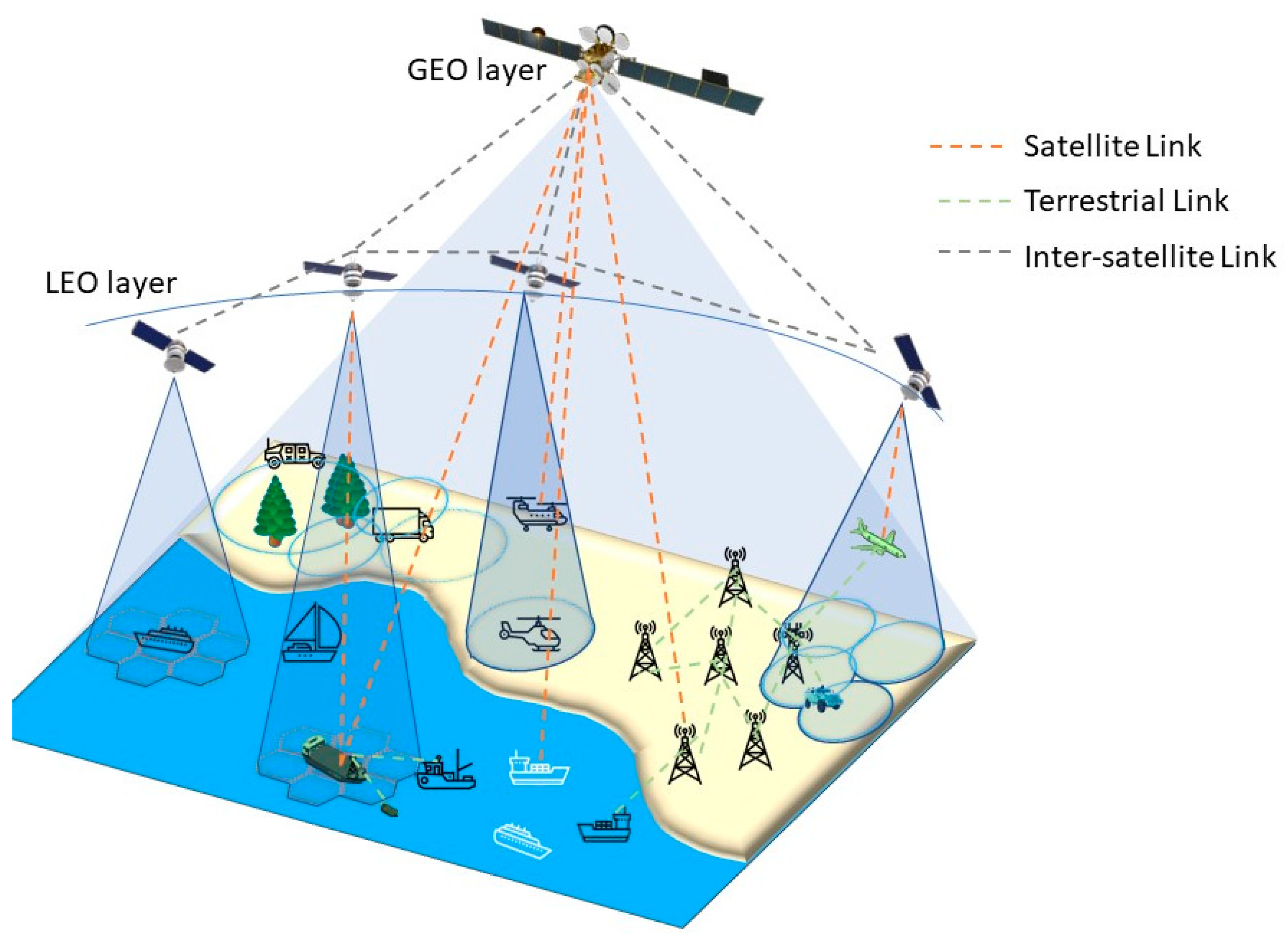
We propose a mission definition for a highly resilient, highly available, and multi-purpose MLSS that adopts at least one GEO satellite layer to be deployed as the first stage of the system, to be later augmented by one or more NGSO satellite layers, with preference for LEO or very-low earth orbit (VLEO) due to low-latency links. Extension to a three-layer structure including, e.g., MEO is possible. The basic concept is depicted in
Figure 1 covering GEO and LEO layers.
For the user link, the proposed system shall operate in one or multiple frequency bands, with at least one mandatory sub-6 GHz frequency band to satisfy user terminal size, weight, power consumption and cost (SWaPC), and antenna constraints (e.g., omnidirectional antennas). The system shall be able to serve handheld and mass IoT use cases and satisfy service availability requirements (such as rain fade resiliency), and an optional high-bandwidth frequency band operating above 10 GHz to satisfy high-throughput broadband use case requirements. A multi-band implementation is considered strongly beneficial but does not have to employ multi-band payloads, by instead splitting band support by layer.
The system shall utilize NTN air interfaces and protocols of the 3GPP at least for the sub-6 GHz operation of the system to support UE including IoT, smartphones, and portable customer-premises equipment (CPE). The adoption of the 3GPP air interface across all layers and frequency bands of the system is considered strongly beneficial to maximize the ground infrastructure’s commonality, seamless mobility, and interoperability. The aim is also to leverage economies of scale and the larger mobile ecosystem, especially for user terminals.
We do not consider the capability of each terminal to be able to connect to all the layers, or even multiple layers of the system to be a baseline requirement for all terminals and use cases. However, for those user terminals and use cases where high availability and reliability are key requirements, this is considered strongly beneficial, if not in some cases required, to fully realize the MLSS strengths in high availability. In such cases, air interface commonality, antenna, and RF frontend commonality become even stronger considerations, and network infrastructure commonality or tight integration is considered a prerequisite.
In other cases, it could also be possible to combine terminals with different air interfaces, antennas, and RF frontends at the network and application layer using an Edge Connectivity and Application manager. Even in such cases, tight network infrastructure integration and some levels of commonality are considered a requirement.
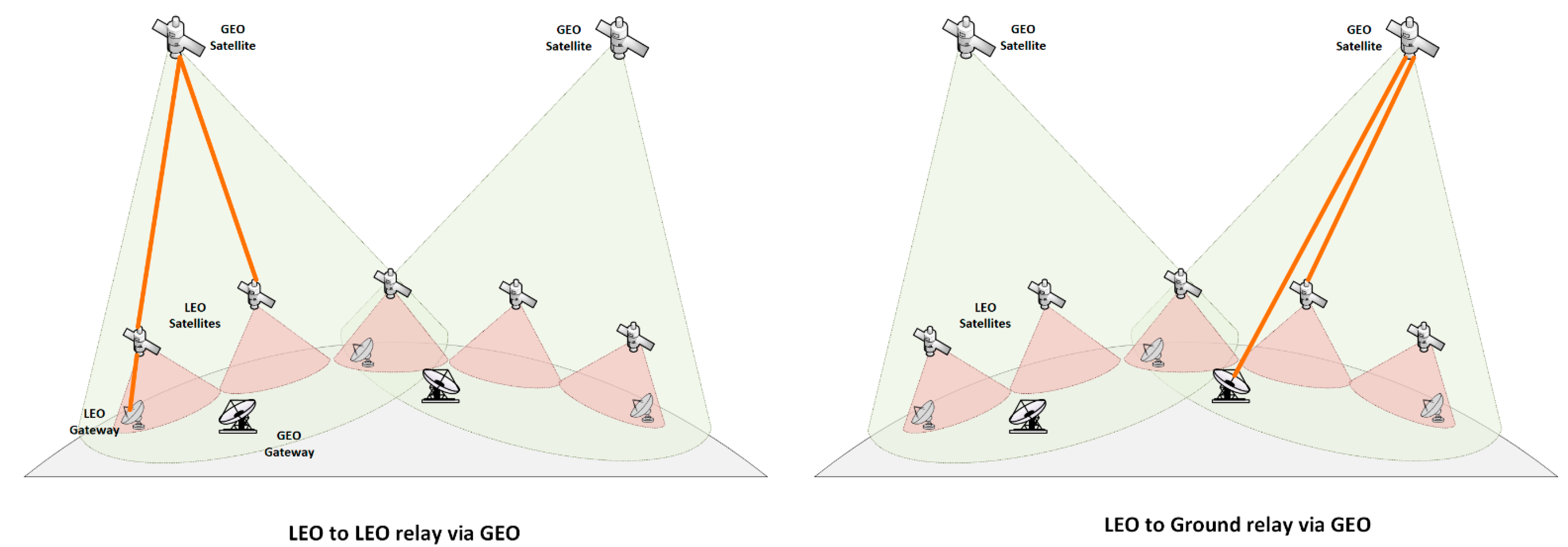
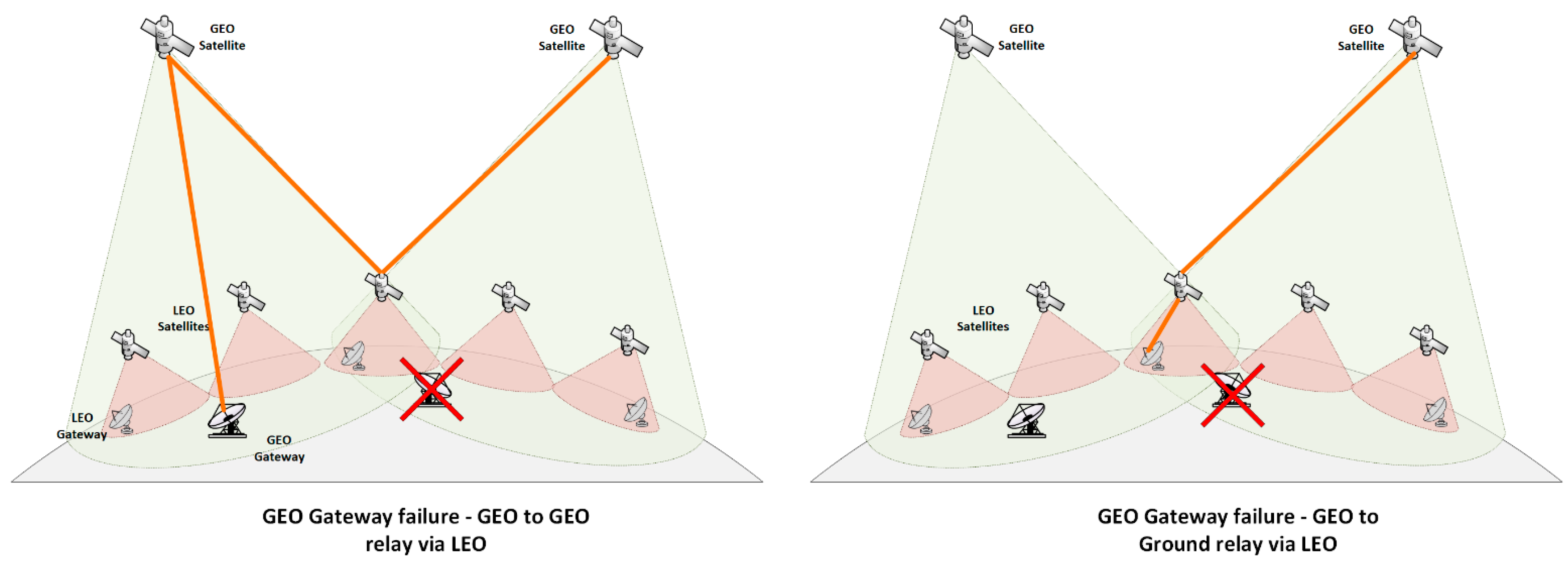
The ability of the GSO system to relay and backhaul (see
Figure 2) data traffic from lower NGSO layers of the system is considered a requirement to fully realize the technical, service, cost, and timeline benefits of the native MLSS design in comparison to multiple disjointed single-layer systems. This capability enables the removal or significant relaxation of the requirement for inter-satellite links between satellites, as well as for a large number of ground stations for the NGSO layers, by allowing traffic served by NGSO layers to be landed via GSO, resulting in fewer large gateways (GWs). Furthermore, it enables the capability to reuse NGSO layers as fallback relays and/or temporary landing gateways for satellites of the GSO layer(s) in case of GSO GW unreachability (see
Figure 3).
Therefore, the support for at least low-bandwidth LEO-GSO links is a baseline requirement to provide LEO-to-GSO backhaul of low-data rate, consumer messaging, IoT, and non-communications type use cases (e.g., scientific research, weather, Earth observation, etc.), with an optional, but beneficial, support for high-bandwidth LEO-GSO links. To achieve this, the GSO layer may employ a sub-6 GHz frequency such as L-band, S-band, or C-band. Alternatively, (or potentially in combination with) a high-frequency band above 10 GHz, such as a Ka-band or Q/V-band, which could be re-used for both GSO-to-ground gateway feeder links, LEO-to-GSO relay and backhaul links, and user links to fixed and mobile VSAT terminals via the implementation of steerable or full-coverage multi-beam HTS/VHTS capability.
The LEO layer shall support at least one sub-6 GHz frequency band, such as an L-, S-, or C-band, for user links, and at least one high-frequency band above 10 GHz, such as a Ku-, Ka-, or Q/V-band, for LEO-to-GSO backhaul and relay capability, as well as LEO gateway steerable feeder links. The LEO high-frequency steerable LEO-to-GSO and LEO-to-ground links could be designed to be sufficiently flexible to be re-pointed to serve as RF LEO-to-LEO inter-satellite links (ISLs) or, in the case of feeder links, as high throughput user links for select high-value mobile and fixed VSAT user terminals.
4.1. Service Operation
The MLSS helps to ensure that a user terminal can register to the system using any available access networks. During the registration process, the user terminal communicates its capability and specifies the list of usable access networks and their expected channel qualities. The user terminal monitors the available access networks and informs the network management entities about any changes. When a connection is initialized, the network management functions determine which of the available access networks would fulfill the quality of service (QoS) requirements most efficiently and orchestrate the end-to-end network accordingly. Any change in the system’s state leads to the reevaluation of the selected radio access method and to its reconfiguration if needed.
From an operational perspective, the main challenge of the MLSS is to configure the end-to-end network in such a way as to fulfill the heterogeneous QoS requirements of the users regardless of their geographical location. At the same time, the MLSS must maximize the efficiency of utilization of the available assets, and the system’s overall capacity. Software-defined networking (SDN) enables dynamic and efficient network management, improving the network’s performance and monitoring. SDN allows the centralization of the network management intelligence for the overall network.
Because the access network of the MLSS can be composed of multiple heterogeneous radio access networks with potentially different air interfaces and/or protocol stacks, the virtualization and disaggregation of the component radio access networks via an open radio access network (O-RAN) architecture simplifies the management and operation of the MLSS and can increase flexibility quite significantly. One of the primary benefits of virtualizing the component RANs is that the individual RAN functions no longer require special proprietary hardware to run and can instead be run on standard servers (RAN processors).
The virtualization should not be limited to the RAN but should start primarily with network functions (NFVs), such as routers, firewalls, etc. The softwarization of these functions means that the specialized hardware is replaced by software running on commodity hardware, preferably on a private or public cloud. To increase the capacity of the global network, a cooperative hierarchical radio resource management system should be used.
4.2. High-Level Architecture (HLA)
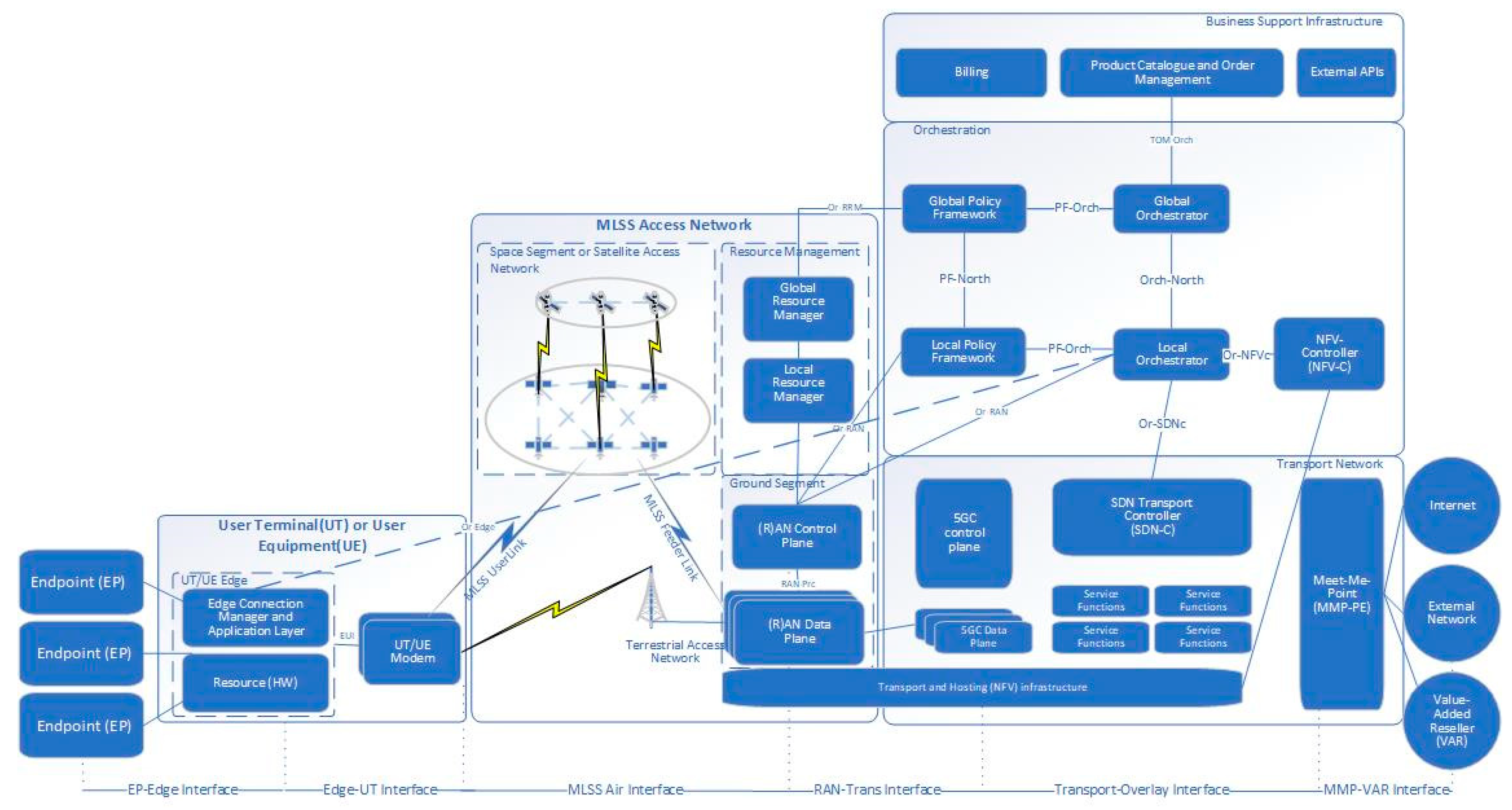
The proposed high-level architecture of the MLSS is depicted in
Figure 4. The space segment has been abstracted in this high-level architecture. The proposed HLA assumes that all constituting Access, Core, and Transport networks are virtualized (vRANs) and programmatically controlled (SDNs). The orchestration and resource management used in various networks have a hierarchical distributed architecture.
Following the 5G satellite–terrestrial convergent network architecture designed for backhauls [
44,
45] and extended for the new 5G NTN connectivity, the MLSS is divided into several main technology building blocks called macroblocks:
User Segment (User Terminal/Equipment) and Edge;
MLSS Access Network, with Space Segment and Ground Segment;
Core and Transport Networks;
Service Orchestration;
Business Support Infrastructure (incl. Product Catalog, Order Management, Billing, etc.).
The edge network is connected to the radio access network through the user terminal. The user terminal can connect to multiple types of access networks. The access networks that form the MLSS Access Network can be terrestrial networks (4G/5G) or non-terrestrial multi-orbit, multi-band, or multi-waveform satellite access networks. Each access network has its own local management functionality, but the behavior of these local managers is controlled and orchestrated by the global orchestration functionalities. Each component of RAN has its own radio resource management functionalities, but these resource managers cooperate with each other to maximize the global capacity. A centralized global resource manager module coordinates the activity of the distributed radio resource manager modules.
Each macro-block can be further subdivided into component blocks or sub-systems, in line with the MLSS high-level architecture (HLA):
User segment and edge consist of UT/UE modems that connect to the edge connection manager and application layer subsystem over the end user interface (EUI). The software is run on the edge HW platform. The endpoints can connect to the user segment with an ethernet or wireless connection.
MLSS access network is responsible for the MLSS air interface. It includes the space segment, i.e., satellites, and the communications payloads in different orbits as well as terrestrial base stations. The ground segment with the RAN infrastructure provides the control plane and data plane functionalities for the access networks. Radio resource management (RRM) is performed with global and local resource managers who manage the whole network as well as optimize local resource use.
Core and transport network hosts the transport and NFV infrastructure, enabling SDN capabilities. It is home to the core network of the system. In addition, the SDN transport controller is in this block, and together with the local orchestrator it manages the whole SDN network and its service functions. The meet-me-point connects the MLSS network to the external networks and internet services.
Service orchestration is the process of designing, creating, delivering, and monitoring network services in an automated way. It is performed with global and local policy framework functions that connect with the RAN control plane and resource managers. The end-to-end orchestration of network services and connections is performed by global and local orchestration blocks. The NFV controller runs the virtual machines that replace the traditional network appliance HW.
Business support infrastructure is a critical functionality of the MLSS operator. It provides external APIs and product catalogs, enables order management, and is responsible for the billing of users. Related functionalities need to be implemented in the system.
5. Results: Findings from Simulations and Testbed Activities
5.1. Simulation Studies
To study the defined system, we implemented a simplified version of it with our simulation software, called SCNE [
46]. The modeled MLSS system was defined with the parameters presented in
Table 2. As depicted in
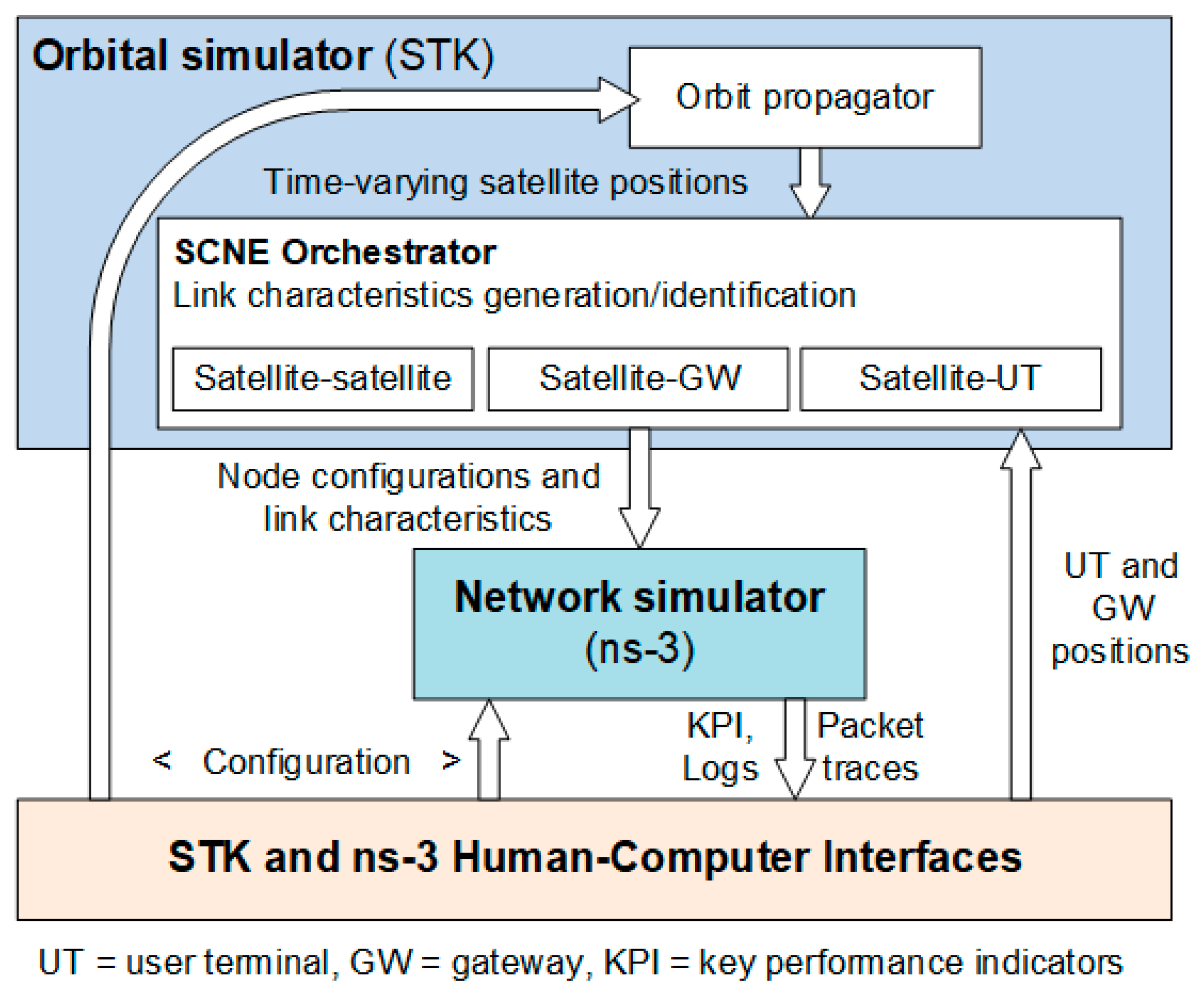
Figure 5, SCNE consists of a Systems Tool Kit (STK) and ns-3 simulators, and an orchestrator between these elements. STK is used for modeling the satellite constellation part, i.e., satellite, gateway, and user terminal locations, and the visibility and link budgets between all nodes. This information is then used in the ns-3 network simulator to create a similar scenario with the physical layer (L1) based on the link characteristics computed in the STK. The upper layers (from L2 to applications) are modeled solely inside ns-3. The role of the orchestrator is to collect and compute all the necessary information from the STK scenario into configuration files that are then read by the ns-3.
The target of the simulation studies was to see whether there are benefits to the use of the MLSS system vs. a single-layer system. Our hypothesis was that the MLSS can support both delay and jitter (as standard deviation from the mean delay) sensitive traffic depending on via which satellite layer the packets are routed, while a single-layer system can support only one of those elements, depending on the orbit. The key performance indicators (KPIs) selected for the performance assessment were end-to-end delay, jitter, packet loss, and throughput. The simulation results (end-to-end delay) also served as inputs to the testbed activities that are described in
Section 5.2. The end-to-end delay is defined as the total delay from the UT via the satellite(s) to the GW.
Results for the simulations are shown in
Figure 6,
Figure 7,
Figure 8 and
Figure 9.
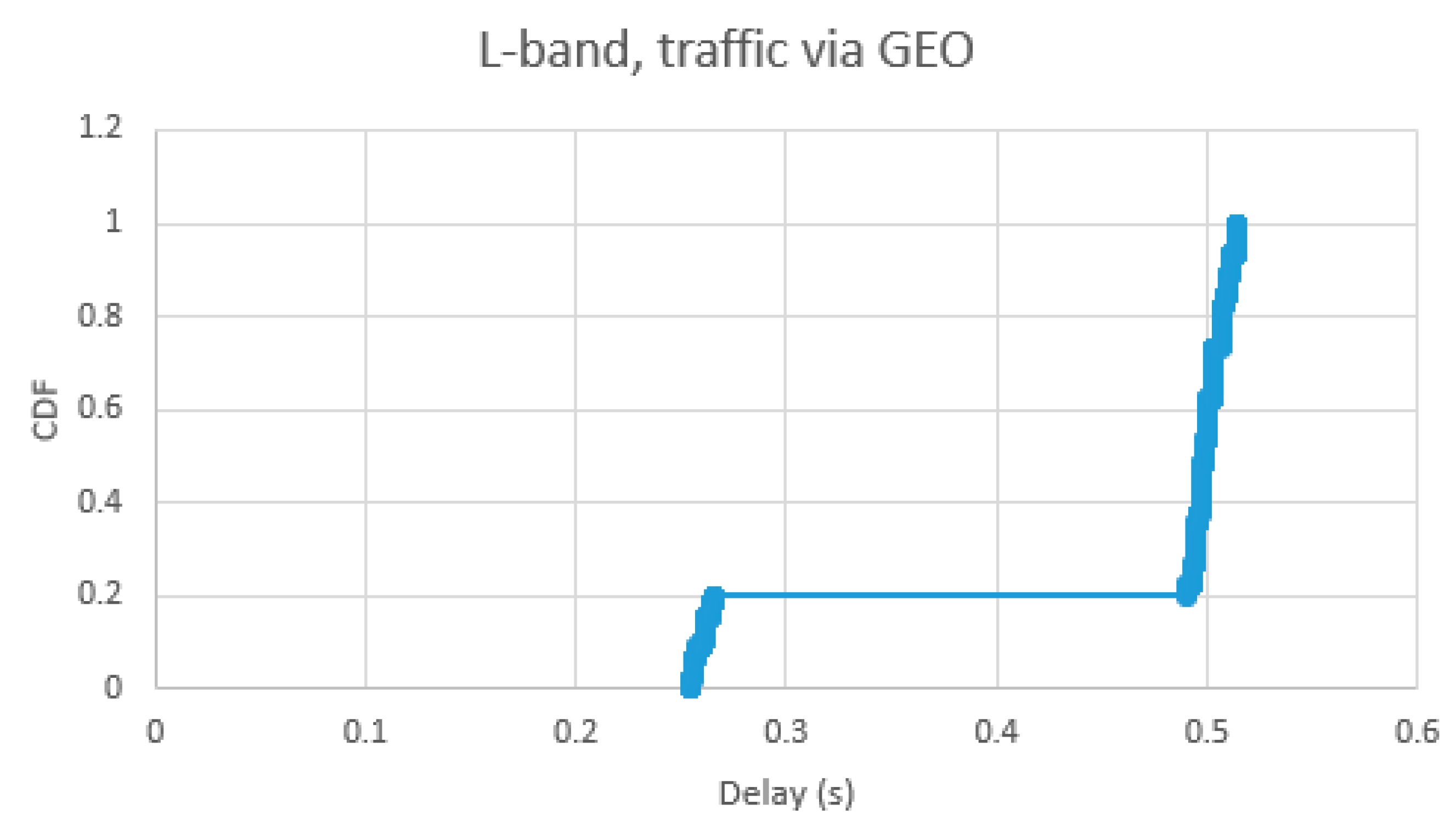
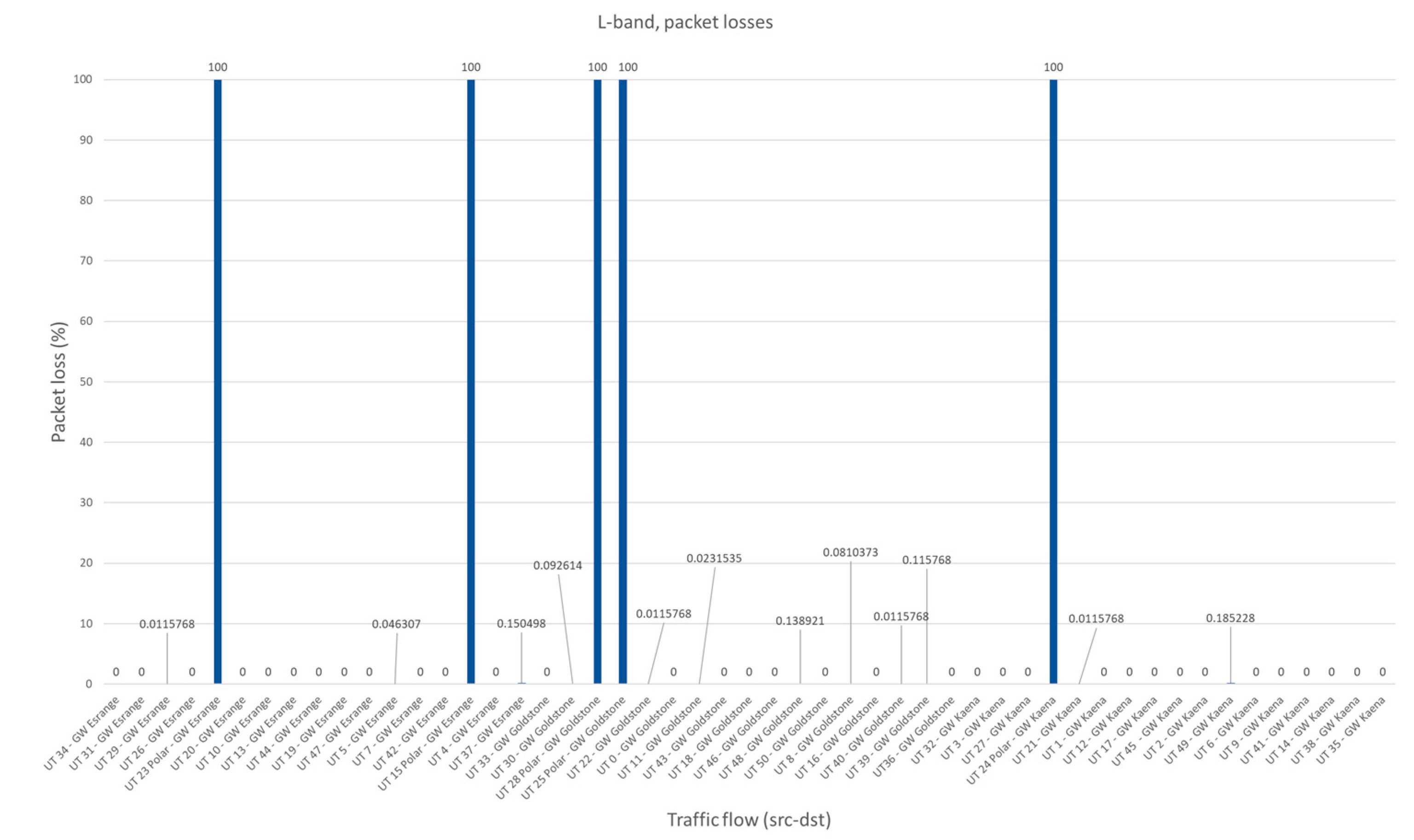
Figure 6 and
Figure 7 present the cumulative distribution function (CDF) of the end-to-end delay and packet loss percentage when the packets were routed only via the GEO layer. In our scenario, about 20% of the packets went only via one GEO satellite, i.e., the source UT and destination GW were located under the same GEO satellite. The end-to-end delay was then around 265 ms. The rest of the packets used a GEO-GEO ISL to reach the other satellite that served the destination GW. The delay was then around 515 ms. In individual UT-GW traffic flows, the jitter (as standard deviation from the mean end-to-end delay of the flow) was between 0.02–0.04 ms.
UTs located in polar areas did not have a connection to the GEO satellite, hence they had 100% packet loss. Otherwise, there were some single packets lost due to bad reception, i.e., a too-high bit error rate. The results were quite similar regardless of the GW location used.
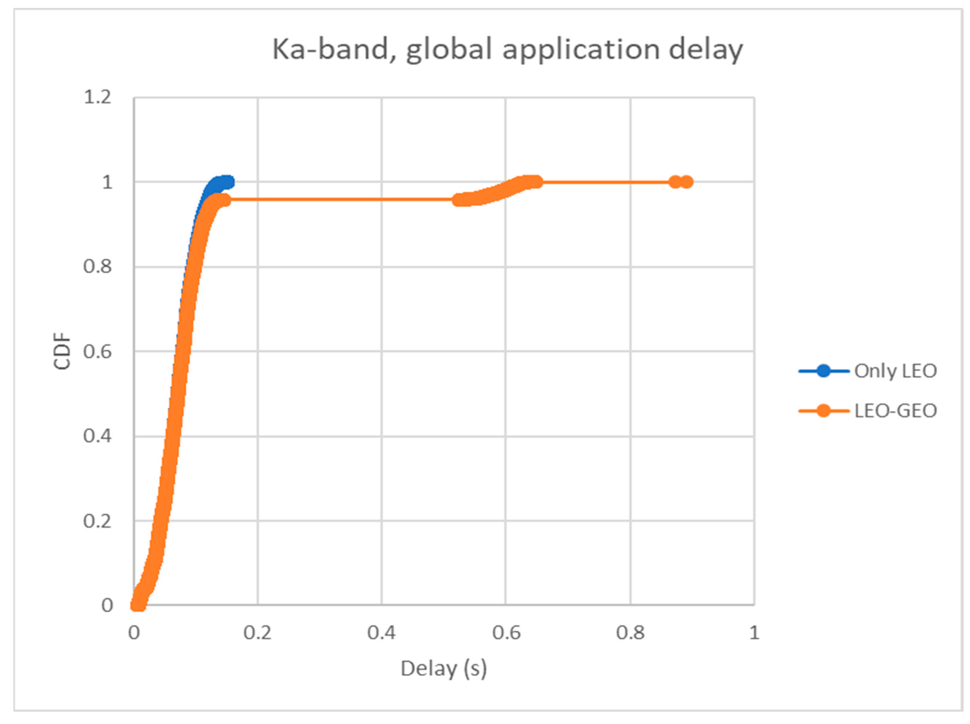
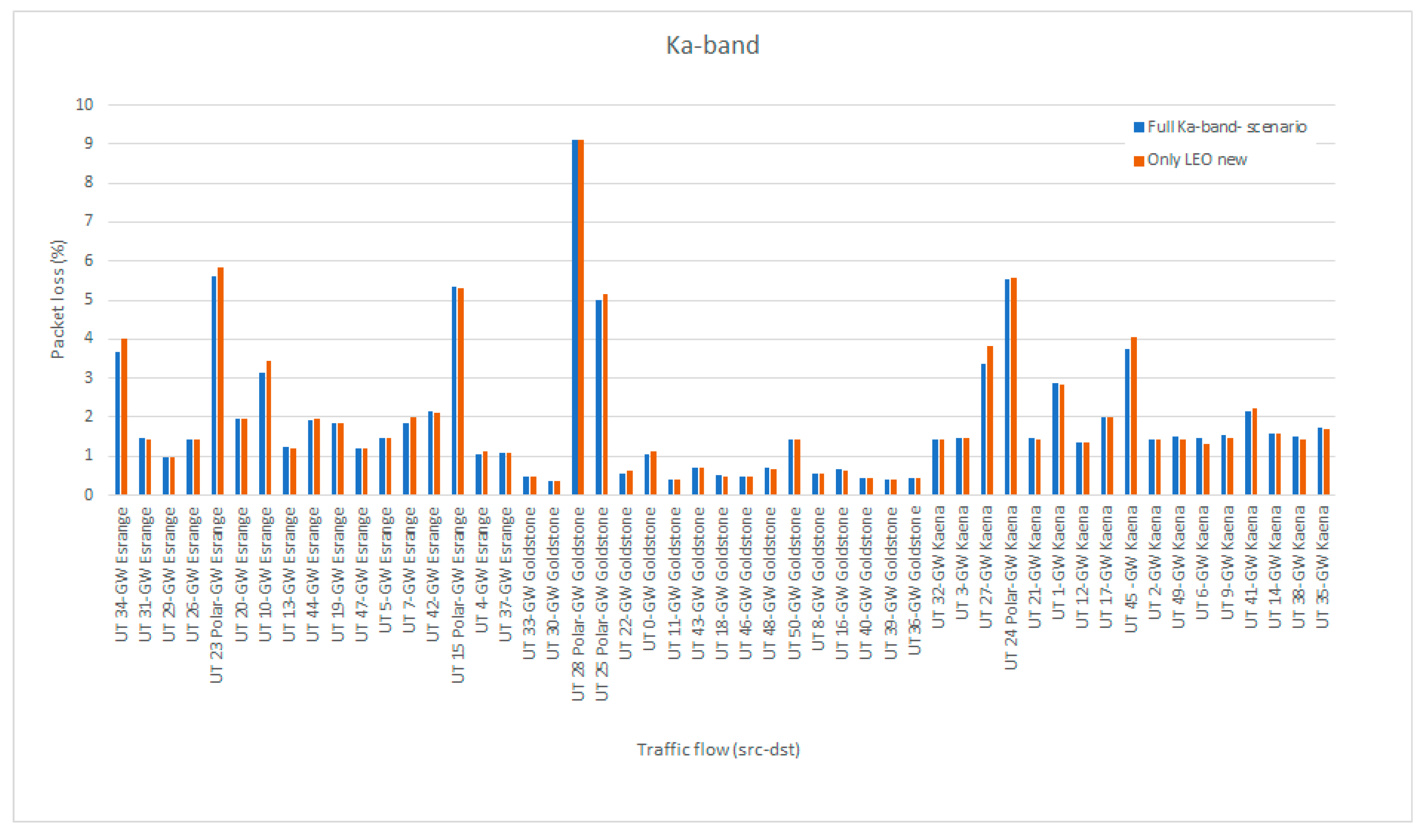
Figure 8 and
Figure 9 present the same statistics for the case when packets were routed only via a LEO layer. Now the average end-to-end delay was 71 ms, with a minimum of 7.3 ms (source and destination under the same LEO satellite) and a maximum of 156 ms (source and destination on the other sides of the Earth). If the GEO layer was also enabled, some packets used the LEO-GEO ISLs and GEO satellites to reach the other side of the Earth with fewer hops than using only the LEO-LEO ISLs. The average delay increased then to 91 ms with a minimum of 9.1 ms and a maximum of 891 ms. Additionally, the jitter increased. For example, a traffic flow in a pure LEO case had a jitter of 31 ms, but, with LEO+GEO, the jitter was 130 ms. The packet loss varied between 0.3–9%. The polar areas were now served by the LEO satellites.
We can conclude that the following lessons were learned from the simulations:
We simulated GEO and LEO partly separately, which was possible due to different routing policies for delay and jitter-sensitive traffic. Delay-sensitive traffic was routed only via LEO and jitter-sensitive via GEO.
SCNE has an ideal global routing protocol that results in similar behavior as the routing protocol proposed in [
47]; the only difference is that, in the beginning, the control messages delivering the computed routes are not modeled in SCNE. Additionally, the mobility management is ideal in SCNE; more reality could be added by modeling the real control messages for it.
The expected benefits of the GEO and LEO layers were present in the simulation results: GEO provided a smaller jitter than LEO, while LEO provided a shorter delay. LEO can serve also polar areas. The results from our own measurements over the OneWeb LEO satellite constellation and the Viasat GEO satellite provide similar findings. However, additional delays are introduced in practical systems due to non-ideal routing mechanisms.
The packet loss was a little bit higher in LEO due to access gaps during LEO-LEO handovers. In SCNE, the handover is seamless (zero delays in switching between satellites) but not lossless. Packets already on the air will be missed if the destination makes a handover at the same time.
The link cost metric in MLSS should not be the number of hops. Or, at least, the GEO hop should have a much higher cost than LEO hops since the distance and delay in GEO is about 36 times greater than that in LEO. Further, the link cost metric could also consider the buffer status to avoid congestion. Routing in MLSS shall be further studied.
The benefits of GEO-LEO ISL were not present in the simulations since routing packets via both layers did not optimize either mean delay or jitter. However, we can think that it could be useful in certain cases, such as delivering packets to the LEO satellite nodes when heavy rain blocks the direct connection from the ground to visible LEO satellites. GEO in the L-band would still work, and it could forward the packets to the LEO layer from above the blocking rain/clouds. GEO could also provide backup routes if some LEO links were congested. However, we did not have this kind of scenario in these first simulations.
5.2. Testbed Activities
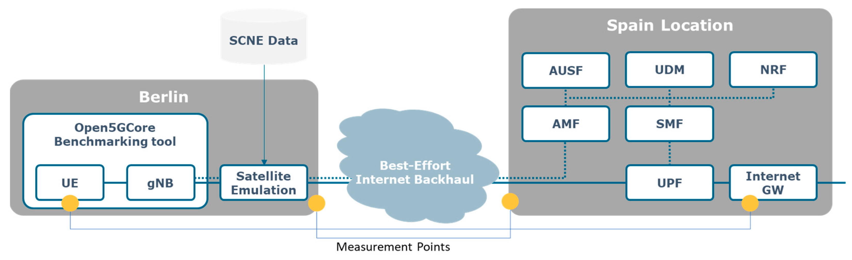
The MLSS testbed is illustrated in
Figure 10. Two different locations, one in Fraunhofer FOKUS in Berlin and one in a controlled location in Spain, were deployed, emulating an end-to-end distributed system like previous testbeds for 5G with GEO backhaul [
48]. To be able to control the end-to-end environment and to execute the measurements the Open5Core benchmarking tool was installed on the Berlin premises emulating the UE and the gNB. This abstracts the local 5G access network, enabling us to concentrate on the impact of the backhaul connectivity. This local 5G radio emulation is specifically important as its delay is highly dependent on the UE and gNB used, ranging from 4–6 ms for high-quality base stations and UEs adapted for minimal delay and up to 100 ms for more prototype or initial products area, thus significantly influencing the measurements. In a final deployment, such delays should be considered, especially when deciding on an end-to-end service delay, as well as on the expected capacity from the specific gNBs deployed.
Co-located in Berlin with the Open5GCore Benchmarking Tool, a satellite emulation script was deployed. The satellite emulation script pushes the SCNE data as parameters every second to a Linux OS Traffic Control (TC) tool, adding to the data plane the respective delay as well as defining a random jitter on top of it for the specific link. To be able to have accurate measurements, the system was synchronized using the Network Time Protocol (NTP) across the best-effort internet. Although it has a worse accuracy compared to the Precision Time Protocol (PTP), it is considered enough for a backhaul with satellite network transport. Additionally, PTP is not expected to function significantly better due to the continuous variable jitter between the locations.
The rest of the core network was deployed in the Spain testbed, emulating a central network location, such as the headquarters of a large enterprise network be it for public protection and disaster relief, maritime, aeronautical, or IoT data aggregation. On the Spain side of the testbed, the control plane components as well as the User Plane Function (UPF) and the gateway to the internet were deployed. The minimal control plane components were deployed.
A two-location setup interconnected with a best-effort internet backhaul was chosen to be able to better emulate the effects of a backhaul. Specifically, we assume that the best-effort backhaul between the Berlin and the Spain location is equivalent to a best-effort backhaul between a satellite gateway and the remote central location of an enterprise network. As both the Berlin and the Spain locations are directly connected with dark fiber to the local operator backhauls, the delays and the jitter of these links are realistic for the selected scenario.
As with these measurements, we were interested in the effects of the backhaul, even though an offloading at the Berlin premise is possible by deploying a local UPF with a specific local Access Point Name (APN) enabling the usage of the local services, this was not used, and it is not depicted.
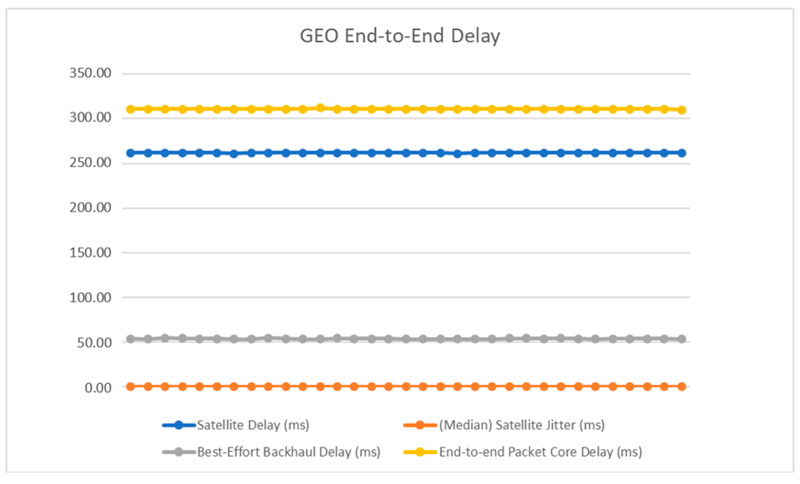
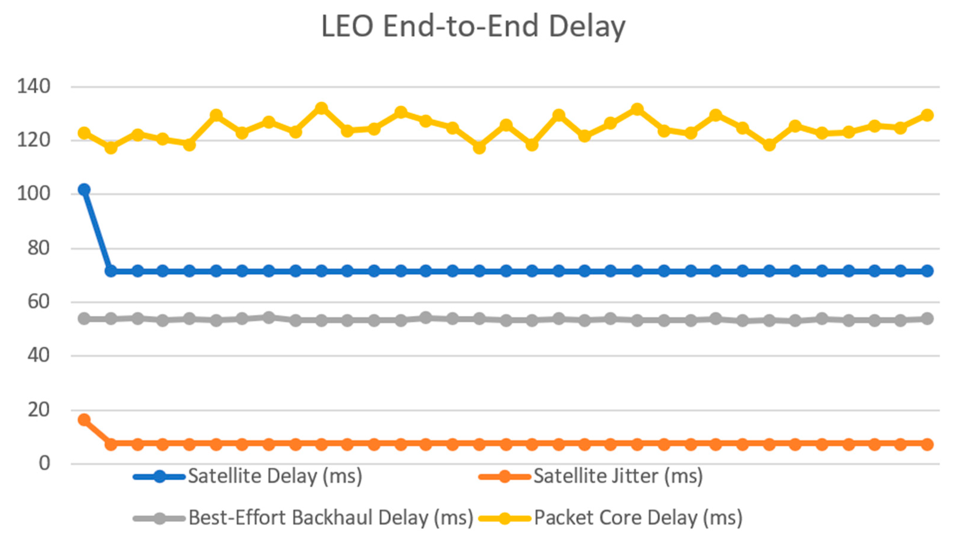
For the data plane, a set of four measurement points were established in the UE, the exit of the Berlin location, the entry of the Spain location, and on the internet GW, the last possible measurement point in the end-to-end connection. With these measurement points, we could assess the end-to-end delay as well as the dependency on the undependable backhaul interconnection between the two locations. Using the data from the SCNE simulator, the following end-to-end delays presented in
Figure 11 and
Figure 12 were obtained for the GEO and the LEO-based data paths.
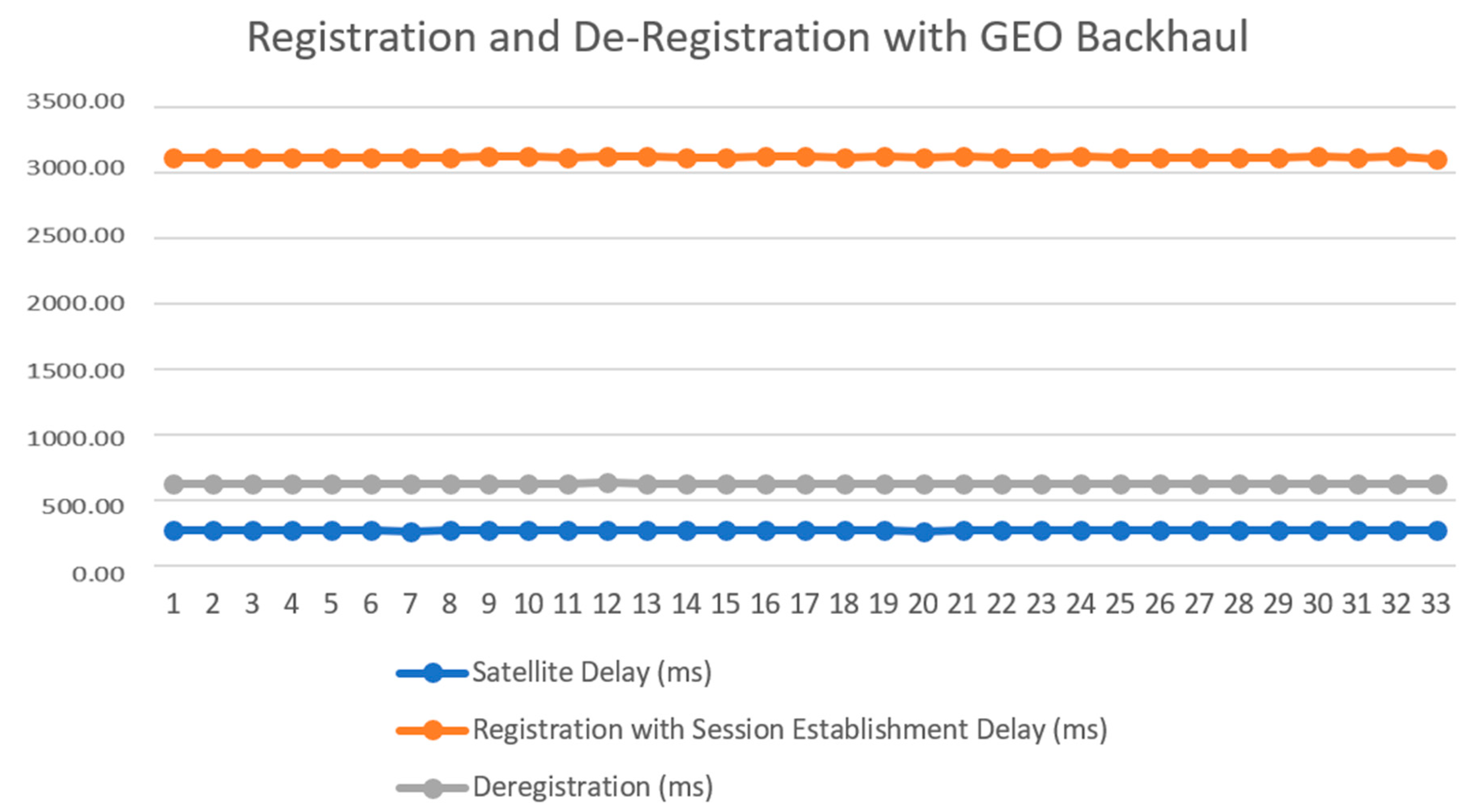
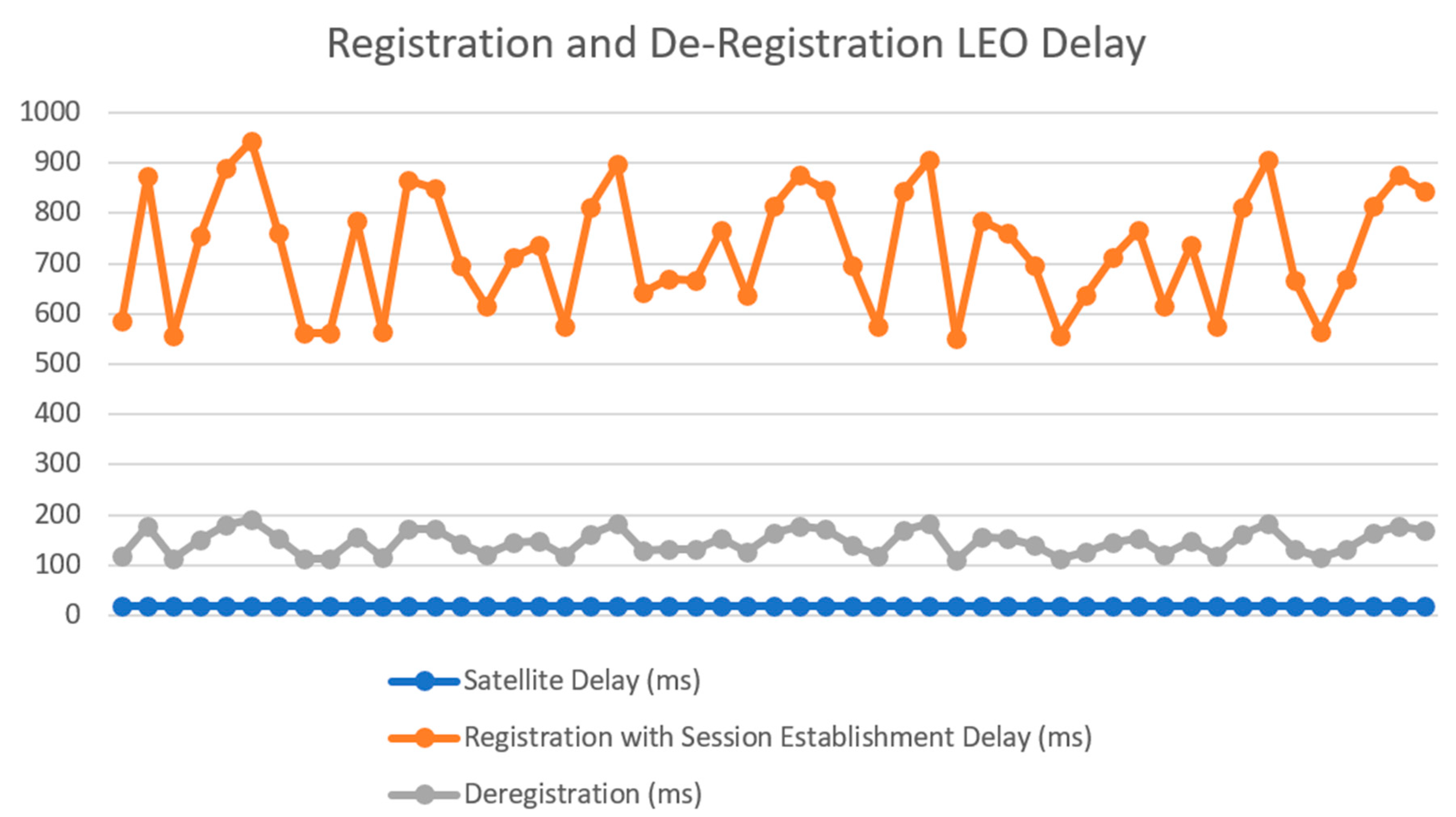
In the control plane, the end-to-end delays presented in
Figure 13 and
Figure 14 were obtained for the GEO and the LEO-based measurements for the Registration with Session Establishment and the Deregistration procedures.
As immediately noticeable from the measurements, the procedures are directly proportionate to the end-to-end delay between the two locations. Specifically, for the Registration with Session Establishment, the delay of the procedure is ten times bigger than the delay of the backhaul, as there are five message exchanges with the UE as part of the registration procedure (Registration Request—Authentication Request, Authentication Response—Security Mode Command, Uplink Network Access Server (NAS) Transport—Initial Context Setup Response, Uplink NAS Transport—Downlink NAS Transport, Uplink NAS Transport—Protocol Data Unit (PDU) Session Resource Setup) while for the Deregistration it is two times bigger than the backhaul delay, as there is a single message exchange (Deregistration request—Deregistration accept). The results for the GEO backhaul confirm previous measurements using real satellite connectivity.
The delay for these procedures is manageable by the core network, being still in the expected time delays for the procedures, even for the GEO case. Furthermore, as we have used a test UE where we have removed the timers, we have had no retransmissions. However, for a commercial UE, the retransmission timers would have to be updated to be able to match the expected delays.
All the tests were executed in a non-stressed environment, with a single request every second. The delay of the local execution of the procedures was added to the delay of the backhaul—i.e., 20–40 ms for the registration procedure with session establishment and 2–4 ms for the deregistration. These extra delays are expected to be maintained until the system becomes loaded, as the procedures for the different UEs are executed in complete isolation from each other, the only common synchronization point being the NAS, and the Hypertext Transfer Protocol (HTTP) interfaces of the different components, i.e., the telecom systems, are very effective at scaling up to the computed load.
When overloaded, the network functions behave with large jitter in their responses. However, these situations are never reached in real telecom networks, and should not be reached in MLSS either as the components should be properly dimensioned and fast enough at scaling to handle such situations.
Similarly to the data plane, the measurements were executed consecutively for the different satellite links emulating handovers between GEO and LEO and between LEOs. However, there was no effect on the tested procedures as they were finishing too fast to be able to predictably isolate one procedure during a handover phase. A more granular satellite network emulator, e.g., a channel emulator, would be needed to enable a more granular behavior capable of being overlapped to different procedure phases.
The main findings regarding the 5G system with the MLSS backhaul are as follows:
Data path jitter considerations: The very large jitter on the NGSO is significantly impacting the behavior of the end-to-end applications. Such a large jitter is uncommon even for wide-area terrestrial networks and should be further studied. As a solution, a Time-Sensitive Network (TSN)-like implementation for NGSO should be considered for end-to-end communication to bring more determinism to the end-to-end connectivity.
Forward Error Correction considerations: As the satellite network may be multi-hop based, and as forward error correction implementation may be in the space nodes, especially for the ISLs, an end-to-end forward error correction should be able to remove the jitter created by the retransmission of lost packets on the NGSO link.
The delay over the GEO link can be considered only three times larger than the delay over the NGSO link in the case of reliable and deterministic communication. This is due to the buffering that is needed to compensate for the large jitter.
Control plane considerations: As expected, there were no limitations in the testbed system due to the increased delay. However, the UE used was software with no retransmission timers. Adding retransmission timers would require their proper customization, considering the different available backhaul links as well as the proper handling of retransmitted messages on the network side, so as not to reach storms of messages for the same procedures. This is only parametrization.
Granularity matters: A more refined granularity of the behavior of the system would offer more conclusive results regarding the specific procedures.
6. Future Research Directions and MLSS Technology Roadmap
In this section, we provide a brief summary of potential research topics as well as a roadmap for the MLSS technology.
MLSS architectural issues. While the first MLSS implementations have included only two vendor-dependent satellite layers, such as GEO and LEO, an apparent development in MLSS architectural design is towards being able to handle more complicated structures including VLEO, highly-elliptical orbit (HEO), high-altitude platform (HAP), and low-altitude platform (LAP). The SDN and open radio access network (O-RAN) concepts, which have been considered for the terrestrial domain for a while, can be expected to be incorporated into the space segment in the future as well, to assist in the flexible and demand-based vendor-independent multilayer architectural designs [
48]. Similarly, the advanced design of more fluid core networks oriented towards the 6G requirements [
49,
50] would provide an additional benefit to the NTN deployments in terms of space capabilities and performance. MLSS can leverage these advances through the deep integration of ISLs and ILLs as part of the inter-node connectivity with guaranteed QoS and mobility support, further optimizing the system towards controlled end-to-end delay and jitter, as well as for extensive system reliability.
MLSS spectrum allocation issues. Considering long-term research directions, dynamic spectrum management (DSM) remains a research topic for the future, requiring updates for the 6G era. There are multiple topics to be advanced, such as defining the most suitable frequency bands for systems and links and the development of spectrum-sharing mechanisms to manage the complexity of a dynamic and mobile 3D network. Flexible resource management with high granularity might require AI-based solutions. When a massive number of devices are involved in 6G networks and require spectrum assignment, AI-enabled spectrum management can intelligently support a massive number of connections and diverse services. New types of challenges will arise in network controller design due to the inclusion of non-terrestrial base stations (BSs) since both the serving and interfering BSs can move at the same time in the 3D plane. A careful analysis between dynamic, AI-based, very fast resource management and more controlled, database-assisted, dynamic spectrum management approaches that can guarantee QoS for all sharing parties is needed.
MLSS link establishment issues. Satellite networks are very actively studied in 3GPP standardization. However, the 5G New Radio (NR) technology and Narrowband IoT (NB-IoT) technology were originally developed for terrestrial systems and only later adapted for satellite links. When we move towards 6G networks, multi-layer technology is considered from the beginning, and NTN-native design for all the required links can be conducted better, with improved performance. The joint optimization of intersatellite links and the location and number of Earth stations is an interesting research direction. From the link perspective, it is essential to study the use of free space optical (FSO) links not only for ISLs and ILLs but also for space-to-ground links. In addition, the network should tolerate some disruptions for reliable EO and IoT data delivery, and, therefore, disruption-tolerant networking (DTN) needs to be included in the link design of future MLSS networks.
MLSS terminal issues. The RF parts of the terminal form one of the most significant bottlenecks to enabling cost-efficient MLSS solutions, and, therefore, deserve further attention in the future, especially for the higher frequencies. Similarly to terrestrial networks, recent full duplexing techniques and flat panel multi-element arrays can open up more efficient terminals for MLSS scenarios. The complexity of user terminals can also be partly addressed by increasing the complexity of the satellite domain. The cost-efficiency comes largely from the marriage of the highly optimized implementation of modem baseband and RF functionalities, as well as the adaptations of air interface protocols that can support seamless multilayer access. It must have an integrated antenna for LEO and GEO and a single modem capable of switching between LEO and GEO processing characteristics.
MLSS network management issues. SDN-based controllers are foreseen as one of the main approaches to achieving a feasible and efficient network management framework. Management decisions involve a sufficient amount of SDN controllers and their placement and roles in the overall MLSS network. The controller placement can also be performed dynamically, involving a specific migration cost. The optimal controller locations and the functional split of access and core network protocols are difficult to decide in a highly dynamic 3D network with different delay profiles, as terrestrial network protocols do not readily tolerate delay increases. It is important to incorporate the effect of the cost of unnecessary (e.g., ping-pong handovers) handovers between ISL and ILL and to minimize the overall cost as well as the trade-off between delay and coverage for different load conditions and heterogeneous traffic demands. Additionally, new approaches that can better handle the large memory requirements of routing protocols are needed for the MLSSs with large constellation sizes. Adding more intelligence and learning ability to the network status is expected to maximize the gains attainable if the system allows for higher computational complexity for control decisions.
MLSS technology roadmap summary. Lastly, we present a concise summary of a roadmap of the MLSS technology by presenting a collection of some key past and expected milestones. In particular, we include some important past integration development steps of different satellite layers including conventional terrestrial/satellite layer integration development, subsequent MLSS testbeds, and anticipated MLSS system features in the future, for which more information for specific technologies is provided, e.g., in [
24,
49,
50,
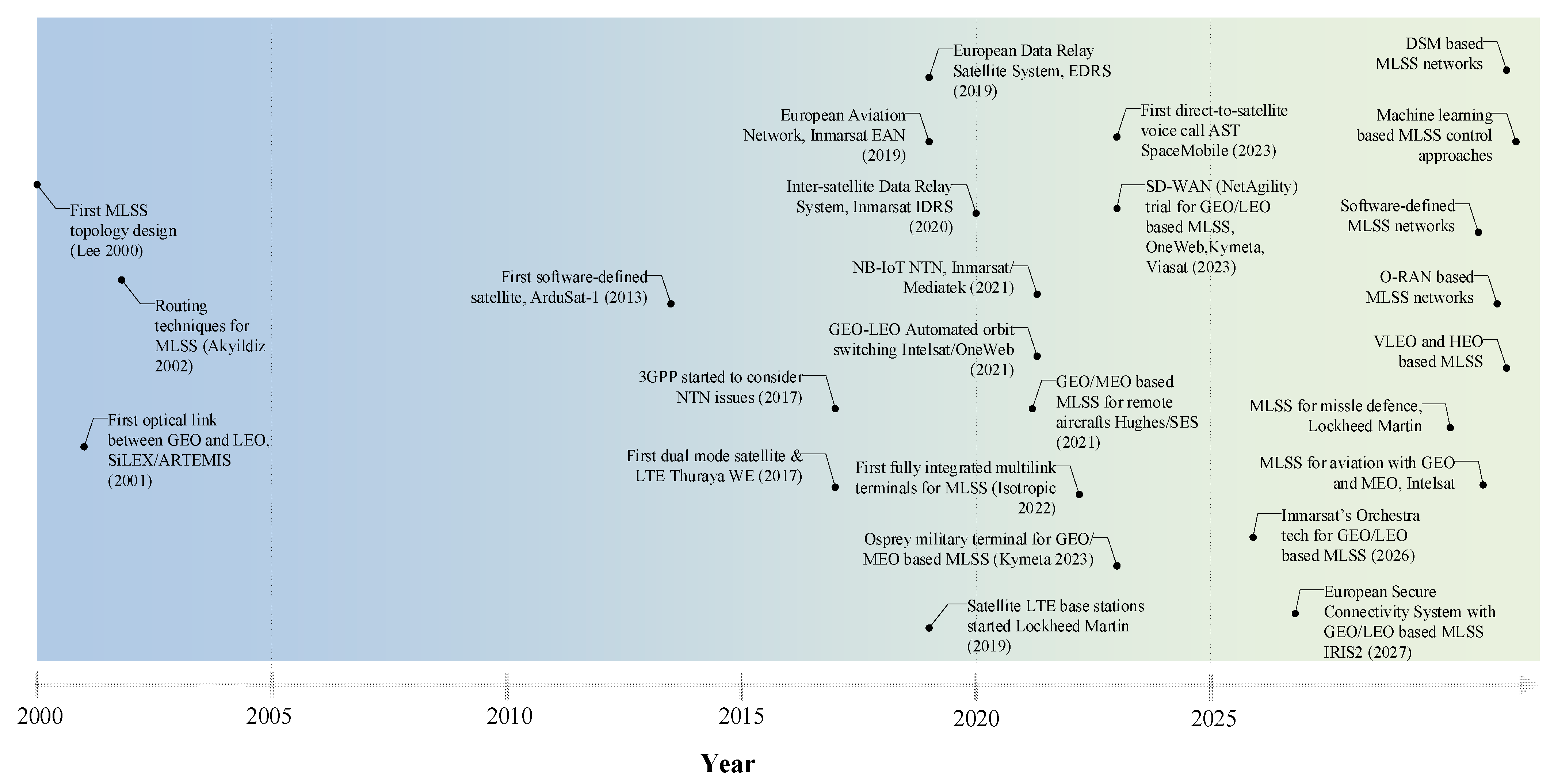
51]. The roadmap illustrating the development trends of MLSS is depicted in
Figure 15. Some main observations of the roadmap include the following:
The first MLSS topology designs were started in 2000 [
52].
Subsequently, several communication methodologies for MLSS started to appear, e.g., for MLSS routing and interlayer links.
The 3GPP started their NTN considerations in Release 15 (2017) and later also conceptualized some MLSS scenarios.
Various kinds of trials and products for satellite and terrestrial integration have been announced, such as the first dual-mode satellite and LTE products in 2017, NB-IoT NTN technologies in 2021, and the first direct-to-satellite voice calls with unmodified cellular handhelds in 2023.
Several MLSS communication trials have appeared between 2019–2023 (Inmarsat, Intelsat, Viasat, SES).
Terminals capable of connecting multiple orbits simultaneously have started to appear in 2022 (Isotropic, Kymeta).
Several other MLSS activities are expected within the next five years (Inmarsat, Lockheed Martin, Intelsat, IRIS2).
The key technology enablers of the MLSS that are expected to be realized in the future in real systems include, e.g., DSM, software-defined satellite networks with resource virtualization, O-RAN satellite technologies, machine learning-based MLSS controlling approaches, and extended constellation structures, e.g., with VLEO and HEO.
Clearly, the ISL and ILL link technologies play a significant role in MLSS system design. The heterogeneous choice between RF and optical transmissions remains an important design problem. This is affected by the satellite capabilities and the set of target user services which may also include Earth observation systems.
In short summary, for successful and robust MLSS missions, what is needed in the coming years, from a technical perspective, is a sufficient level of integration in different domains regarding standardization for unifying all subnetworks properly on different layers, a spectrum-sharing framework for interference mitigation, a network architecture with flexible 3D network control (access, resources, and routing) and data architecture, and a unified terminal air interface with user identity/location to support dynamically changing cells and layers.


 and
and 


