1. Introduction
A criminal planning to intentionally break the law does not manifest their intentions. The aim is to remain unnoticed by those in their surroundings for as long as possible, especially by security institutions such as the police, intelligence, and counterintelligence services. The main operational and reconnaissance method of state services is the observation of people, places, and things; therefore, from the perspective of a criminal, and often a criminal group, it is completely justified to carry out counter-intelligence activities [
1]. Criminals carefully plan their next moves. They do everything possible to ensure that the process of gathering information, which could aid in committing a prohibited act, is unnoticed. They meticulously cover up traces that could indicate who committed the crime. If the crime is ongoing or meant to last for a longer period, the criminal disguises their presence and the manner in which the crime was committed. Describing the criminal mechanism is not a praise for the level of intelligence and cunning of criminals; it only indicates the costs incurred during the commission of crimes. For the commission of a crime to be profitable for the criminal (taking into account the costs of preparation and the probability of punishment), the value of the object of the crime must be significantly higher than the costs.
Cybercriminals may also follow a pattern. The process of gathering information about a system is called reconnaissance [
2,
3]. Paradoxically, reconnaissance was originally used to gather information about systems in order to identify security vulnerabilities. Originally, it was an ethical hacking technique that allowed network owners to better secure their systems after identifying security gaps. It should be noted that not all hackers are criminals. The term “hacker” is frequently misapplied to individuals engaging in malicious security breaches for personal gain, often with criminal intentions. In hacker communities, such people are called crackers. Over the years, reconnaissance has evolved from an ethical hacking procedure to a mechanism of cyber attack. A reconnaissance attack is a process in which the hacker takes on the role of a secret detective to obtain information about target systems. This information is then used to identify security vulnerabilities before launching an attack or to pinpoint resources that may be targeted.
Reconnaissance attacks are most often carried out from within the targeted system. We distinguish between active and passive reconnaissance [
4]. In active reconnaissance, the attacker interacts directly with the target. This can take place on multiple levels. To obtain confidential information, the attacker may use social engineering, such as sending emails, using chatbots, or other interactive communication means, to establish a connection. Another method is port scanning, which entails checking open (active) Transmission Control Protocol (TCP) or User Datagram Protocol (UDP) protocol ports by sending data transfer requests to the tested ports. Active footprinting is also a technique used, involving actions aimed at checking active Internet Protocol (IP) addresses or email addresses, by interacting with the relevant services. Active reconnaissance is extremely efficient, as it is targeted at obtaining data essential for conducting an attack and is relatively quick. A notable defense feature against such attacks is the possibility of detection, since the attacker’s interactions with the system can be identified as deviations from normal activity. The second type of reconnaissance is passive reconnaissance. In this approach, the attacker does not directly interact with the user or their system. They conduct their investigation remotely, monitoring traffic and interactions on the network. The attacker can collect and analyze data from public resources, in a process known as open source intelligence (OSINT) [
5]. Both individuals and networks disseminate their information on the network, whether intentionally or unintentionally. A person conducting reconnaissance can utilize Open Source Intelligence (OSINT) to obtain valuable information about a system.
Just as there is no human activity or action that is not in some way fraught with some risk that may affect health or life, no network exists that has not been or will not be the target of an attack. The attacker has many ways to “lurk” within the system, including using social engineering, exploiting breaks in the supply chain, or deploying zero-day attacks. Therefore, it is necessary to take actions aimed at making reconnaissance difficult. One possible method involves disorienting the attacker by indicating that the collected data are worthless, which means the process of collection and analysis must start from scratch. This could result in an increased cost of the attack, potentially rendering it unprofitable. This also increases the chances of detecting the attacker. One such method is Moving Target Defense (MTD), in which dynamic changes are made to the parameters of the protected system that enable its identification or determine its structure [
6]. A significant drawback of the method is that involves changes made to an operating system, which can affect the continuity of provided services. This paper proposes a method for the dynamic mutation of IP addresses of hosts operating in a protected network. IP address mutation is not a new technique for hindering reconnaissance. A drawback of the published solutions is that they do not account for the transitional state in which network IP addressing is inconsistent. This oversight can cause disruptions in the service at the transport layer level, interrupting established TCP connections. This can lead to data loss, thereby degrading the level of Quality of Service (QoS) [
7,
8,
9]. The presented IP mutation mechanisms in many implementations utilize the Dynamic Host Configuration Protocol (DHCP) to change IP addresses. In such a scenario, simultaneous IP address changes by all devices operating in the network are not possible. Moreover, this may require introducing changes at the operating system level to adjust the operation of network applications to the IP address changes. The aim of this study was to develop a solution utilizing IP address mutation that does not affect the functioning of transport-layer protocols. Since IP address mutation is completely transparent to protocols using IP protocol services, it avoids connection interruption or data loss. In the proposed solution, Software-Defined Network (SDN) is utilized [
10,
11,
12]. However, the characteristics of SDN networks alone do not address the issue of of maintaining TCP connections. In the proposed solution, the Protocol-Independent Packet Processor Programming (P4) language and the Portable Switch Architecture (PSA) are employed, which offer another level of freedom in preparing network applications. The ability to implement packet processing algorithms directly in the data path helps to resolve the issue of temporary inconsistency in IP addressing.
This article is organized as follows: The next section contains a literature review on MTD techniques.
Section 3 introduces the concept of SDNs. Since every network equipment provider currently introduces their own solutions that fall within the SDN domain, the we describe the most crucial elements of SDNs used in implementation. The next section provides a description of the individual stages of the cyberattack process and how to defend against it, introducing the ideas behind the MTD technique.
Section 5 contains a description of the P4 language, focusing on presenting the most important elements of the language essential for understanding the operation of the algorithm. In the following section, an evaluation of the performance of the MTD mechanism using IP address mutation is performed. The network convergence time was determined, i.e., the time after which all switches use only mutated IP addresses belonging to the same group, referred to as a generation. We also present formulas specifying how often addresses can be mutated. The next section provides a detailed description of the proposed MTD mechanism and its implementation using a simple model (V1Model) of the P4 switch. This article concludes with conclusions and plans for further research work.
2. State of the Art
The evolution of networks and computer systems has also forced the evolution of cyberattacks. Cyberattacks that were used 10 or 20 years ago are now considered simple or even primitive. The attacks used currently can be classified as smart attacks. Modern attacks, which use innovative approaches, are difficult to detect and resistant to traditional methods of defense. The reputation that an attacker could achieve in their environment has ceased to be a sufficient form of gratification. Attacks have become a source of livelihood for whole groups of people. Often, their execution is supported by funds from various organizations or governments that are considered to support terrorism. Such attacks have become very complicated and are adapted to the changing conditions of the attacked area. Only intelligent defense mechanisms can counteract intelligent attacks. Among such mechanisms, we include the MTD technique.
MTD can be applied at many levels: data, application, runtime environment, operating system, or hardware. Moving target techniques in the dynamic data domain change the format, syntax, representation, or encoding of application data to complicate attacks. An interesting use of dynamic data techniques is data space randomization (DSR), where either the data space or the program code is modified [
13]. Another example of an MTD technique, which falls within the category of dynamic applications, involves an environment utilizing several web application servers that perform the same functions. The MTD mechanisms used in this solution dynamically redirect client requests to any chosen server [
14]. This mitigates the effects of vulnerabilities in server software. A product by Morphisec Labs exemplifies a dynamic runtime environment, a technique where the execution environment, including RAM addresses and instruction sets, changes dynamically [
15]. In computer systems, the operating system, memory, and processor, with its instruction set being closely related, are interconnected. Therefore, MTD techniques covering these three elements are treated as a whole and are collectively referred to as a dynamic platform. Examples of the solutions in this area can be found in [
16,
17,
18].
The most explored research area in the field of MTD is dynamic networks. The techniques proposed in this area suggest modifications to a wide range of parameters. The proposed solutions include dynamic modifications to network topology. The initiation can be triggered randomly [
19,
20] or at predefined times [
21]. Another way to hinder reconnaissance is by changing the paths along which data are exchanged between two hosts [
22,
23,
24,
25,
26]. In addition to changing the routes between two hosts, modifications to computer networks can also dynamically alter routing protocol data [
27,
28]. As a result, changes in the network structure are more extensive. Beyond affecting switches and routers, it is also possible to implement changes that exclusively involve hosts. For example, random or timer-triggered changes in port numbers in established connections are possible [
29,
30,
31].The method most commonly representation in the literature is IP address mutations [
12,
22,
26,
32,
33,
34,
35,
36,
37]. As with other methods, the change in IP addresses can be initiated at random moments, at times determined by an algorithm (e.g., from game theory [
38]), or by detecting anomalies indicating third-party activity. To detect anomalies, specially prepared devices, so-called honeypots [
9,
39], can be used.
3. SDN Concept
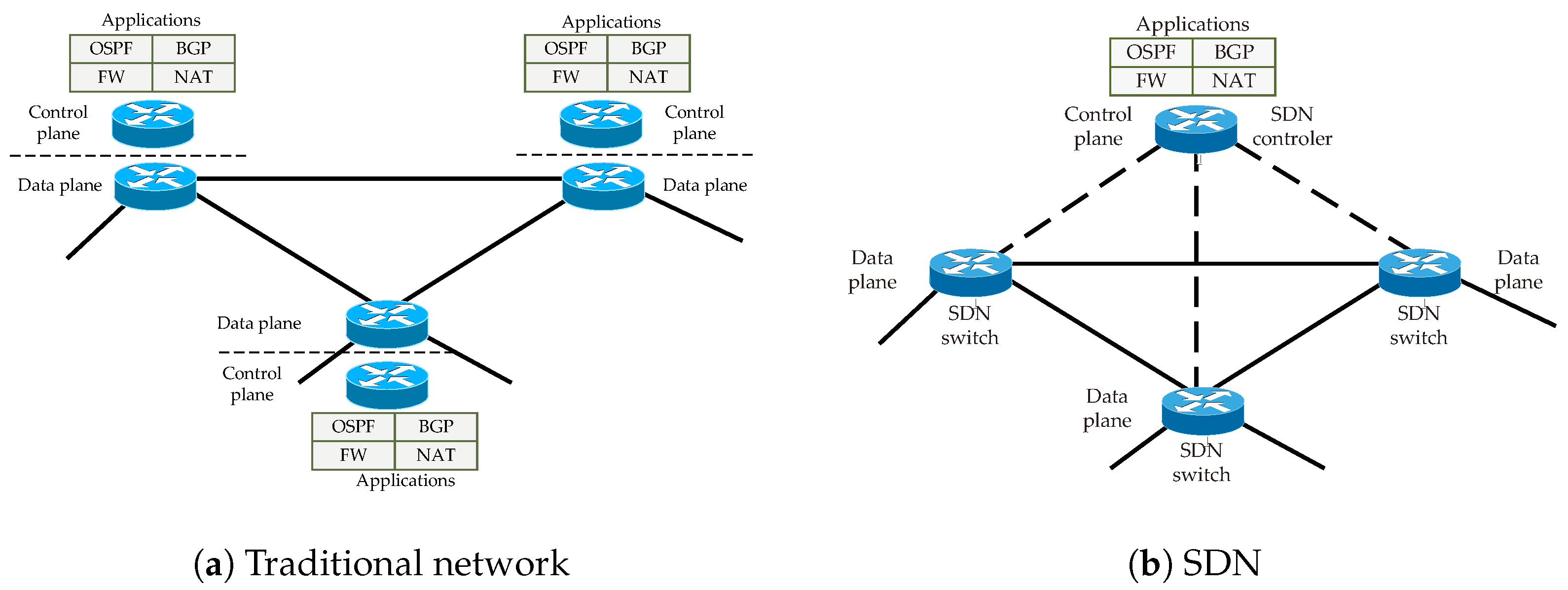
In traditional computer networks, each network node, such as a switch or router, has a fully implemented data plane and a control plane. The proper functioning of such a network necessitates applications running on individual nodes be compatible with each other. Considering that computer networks comprise heterogeneous devices, i.e., from different manufacturers and running different operating systems, application interoperability is sometimes significantly hindered. Furthermore, the need to ensure cooperation between applications restricts the functionality of the network being built. To make a particular service available throughout the network, control-layer applications must be running on all network devices (see
Figure 1a). Naturally, applications that perform basic network functions, such as handling routing protocols, i.e., Open Shortest Path First (OSPF), Intermediate System to Intermediate System (IS-IS), Border Gateway Protocol (BGP), etc., or the DHCP protocol, are typically integrated in the operating systems of network devices. The use of advanced functions or applications necessitates their incorporation into the software stack of network devices, which is often an extremely difficult task.
In SDNs, device planes are separated, with only the data plane implemented within the devices, and the control plane is separate, as shown in
Figure 1b. Devices that perform the tasks of the data plane, known as SDN switches, are responsible for forwarding data between their inputs and outputs. A set of SDN switches managed by the same SDN controller is called an SDN. The rules for forwarding data are defined by devices that perform control plane functions, known as SDN controllers. Information about the rules governing the operation of SDN switches is stored in flow tables. Data exchange between the controller and SDN switches can occur using the standard OpenFlow protocol. The primary advantage of SDN networks is their configurational flexibility and the ease of adding new services and enabling virtualization. This is made possible by using an SDN controller as a central device. In many solutions, centralizing control functions can become a bottleneck for network performance. However, in SDNs, centralizing the control layer along with flow tables on each device implementing the data plane increases network efficiency, allowing for the customization of the features offered to meet user requirements.
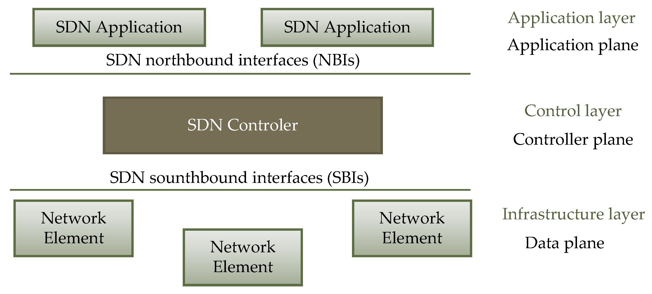
The structure of SDNs is defined by the Open Networking Foundation (ONF) [
40]. In
Figure 2, the basic elements of an SDN are presented. The architecture and elements defined by the ONF should be considered as recommendations only. Each network equipment provider may employ a different approach and their own solutions when it comes to implementing SDNs. The vast majority of network hardware providers utilize the ONF recommendations, in which each SDN controller implements at least two types of interfaces, as shown in
Figure 2. The northbound interface is used for communication between the SDN controller and user applications. By using Application Programming Interfaces (APIs) software, applications can influence the operation of the entire network by implementing various scenarios. The availability of a wide range of SDN controllers written in various programming languages allows for the selection of a solution tailored to the specific requirements. The ability to add applications that implement nonstandard functions is a significant advantage of SDNs. Another key component is the southbound interface, which facilitates the exchange of information between the SDN controller and the SDN switch. Through this interface, the controller receives telemetry data from the attached SDN switches and sends flow table updates.
The well-known protocol used for data exchange through the southbound interface is the OpenFlow protocol, as described in the standard [
41]. Its purpose is to modify the flow table in the controller. As shown in
Figure 3, the SDN switch implements a table that consists of two parts: a match part and an action part. From each packet that arrives at the switch’s input, data are extracted from the headers of the protocols. These can include the source and destination Media Access Control (MAC) addresses, source and destination IP addresses, protocol type, source, and destination TCP ports. The data are used to look up the appropriate entry in the flow table. In the second part of the flow table, there is information about what action (forwarding to a specific port, removal, modification) needs to be taken on the received packet. The data are generated by the corresponding SDN application. The goal of the OpenFlow protocol is to deliver the data to the SDN switch in a secure and reliable manner. If necessary, the OpenFlow protocol can remove or modify entries in the flow table. In the case of packets for which no matching entry is found in the flow table, the OpenFlow protocol delivers the packet or its fragment to the SDN controller. The controller can then send it to the appropriate SDN application to determine the rules to be added to the flow table. Subsequent packets are then handled according to the updated contents of the flow table. The final task of the OpenFlow protocol is to provide telemetry information from the SDN switch to the relevant SDN applications.
In many cases, the use of a central element is considered a disadvantage because it can become a bottleneck in transmission. In the past, decentralized and distributed control was thought to offer higher efficiency. However, the emergence of SDNs has prompted a re-evaluation of the usefulness of centralized control. A wide range of applications that can participate in preparing the data placed in flow tables, a view of the entire controlled network, and the ability to achieve routing convergence almost instantly are just some of the advantages of SDNs. Another highly important feature of SDNs is the processing control information in only one network element. In the case of routing protocols, e.g., OSPF and IS-IS, or ethernet redundancy protocols like Spanning Tree Protocol (STP) each network node independently creates a view of the network. This leads to each node processing the same data. Utilizing a central element that performs the necessary calculations only once not only reduces electricity consumption but also places SDNs in the category of energy-aware networks.
4. Moving Target Defense
To protect networks from cyberattacks, administrators utilize well-prepared security policies and implement best practices for network maintenance and configuration. They have access to a wide range of advanced tools and procedures, such as software updates to patch vulnerabilities and event log analysis to detect attack-related events or network anomalies. Unfortunately, these techniques are also well known to network attackers.
Between the discovery of a software vulnerability and the release of an update, several days typically pass, and updates are typically performed when the system requiring the update is not in use. This delay provides a significant window of opportunity for carrying out zero-day attacks. Event log analysis may become ineffective when an attack is executed using custom malicious software, which can be challenging to detect or prevent with intrusion detection systems and antivirus tools.
To prepare an effective defense against cyberattacks, the attack process used by adversaries must be understood, and the attack process from the attacker’s perspective must be analyzed. Executing a sophisticated and impactful attack on a major network operator, financial organization, government institution, etc., requires substantial financial investments. Attacks on such entities are carried out by Advanced Persistent Threat (APT) groups, sponsored by wealthy organizations or states, driven by economic or political motives. An APT gains access to a computer network and remains undetected for an extended period.
To counteract such activities, understanding what data can be collected by the APT with access to the network is crucial. Identifying the categories of data accessible to the attacking entity enables the pinpointing of potential attack types.
To better understand the entire attack process, the Cyber Kill Chain (CKC) defined in [
42] can be used. It consists of the following stages:
Reconnaissance—This phase involves gathering data about the environment where the attack will take place. The monitoring area can be extensive, including network parameters such as used protocols and their versions, IP addresses, port numbers, load information, types and versions of applications and operating systems, and the types of services being used or provided.
Weaponization—Based on the data obtained in the first stage, the attacker employs various tools and techniques to prepare a payload for a targeted attack. This takes the form of a phishing email, an infected document, or even a modification of a delivered update (by tampering with the supply chain).
Delivery—The payload prepared in the previous step must be delivered to the targeted system to initiate infection. The attacker often leverages human factors, typically involving employees of the company or institution, to bypass authentication procedures. Another method of payload delivery may involve exploiting system vulnerabilities or compromising the supply chain.
Exploitation—This stage involves executing malicious code, rendering the infected system accessible to the attacker. The attacker gains increased privileges, typically through exploiting a known vulnerability or a zero-day exploit
Installation—With increased privileges, the attacker can install malicious software on the victim’s computer or begin gathering information from the victim’s databases for further actions.
Command and Control—This stage includes actions aimed at maintaining remote control over the victim’s machine.
Actions on Objectives—This is the final stage of the attack, involving actions related to achieving the attacker’s objectives. These actions may include downloading critical data, disrupting services, or using the victim’s system to conduct further attacks, this time from a trusted system.
MTD is a cybersecurity strategy classified as a dynamic strategy, aimed at actively protecting computer systems, networks, and data by continuously changing the parameters that constitute the so-called attack surface. The attack surface is the space that attackers must explore or reconstruct to determine the configuration of the target system before initiating the actual attack. It comprises all the points through which attackers can enter the system, indicating which components can be exploited.
MTD is an extremely broad concept, encompassing virtually all levels of networks and computer systems:
At the data level, where the data format or representation can be changed;
At the application level, considering dynamic changes to application code, such as during compilation;
At the runtime environment level, dynamic changes may include random memory allocation for storing critical data;
At the operating systems level, utilizing dynamic changes in instruction sets or entire operating systems;
At the hardware level, involving techniques related to memory, processors, and networks. The first two techniques can utilize methods proposed for operating systems. Techniques used for dynamic changes are much broader and can include, among other things, changes to layer 2 and/or layer 3 addresses, TCP and UDP protocol port numbers, protocol types, and other network parameters.
Changes can be made periodically or randomly. It is also possible to use decoys in the form of servers or stub networks, where the detection of events unrelated to the standard network operations triggers MTD mechanisms. MTD confuses attackers, making it difficult for them to establish a foothold and exploit vulnerabilities in the system.
Implementing MTD mechanisms provides an advantage over attackers by forcing them to confront a constantly evolving and challenging target, thereby increasing the complexity and cost of attacks. This dynamic state is not present in traditional networks, which are characterized by static security measures stemming from fixed configurations and patterns.
5. Protocol-Independent Packet Processors Programming
The first version of the P4 language was developed by a team from Stanford University in 2014 [
43]. The first language specification was also published in 2014, and was designated P4
14. Two years later, in 2016, the P4
14 standard was replaced by the P4
16 standard, which is currently in use. The latest version of the P4
16 standard is version 1.2.4 [
44].
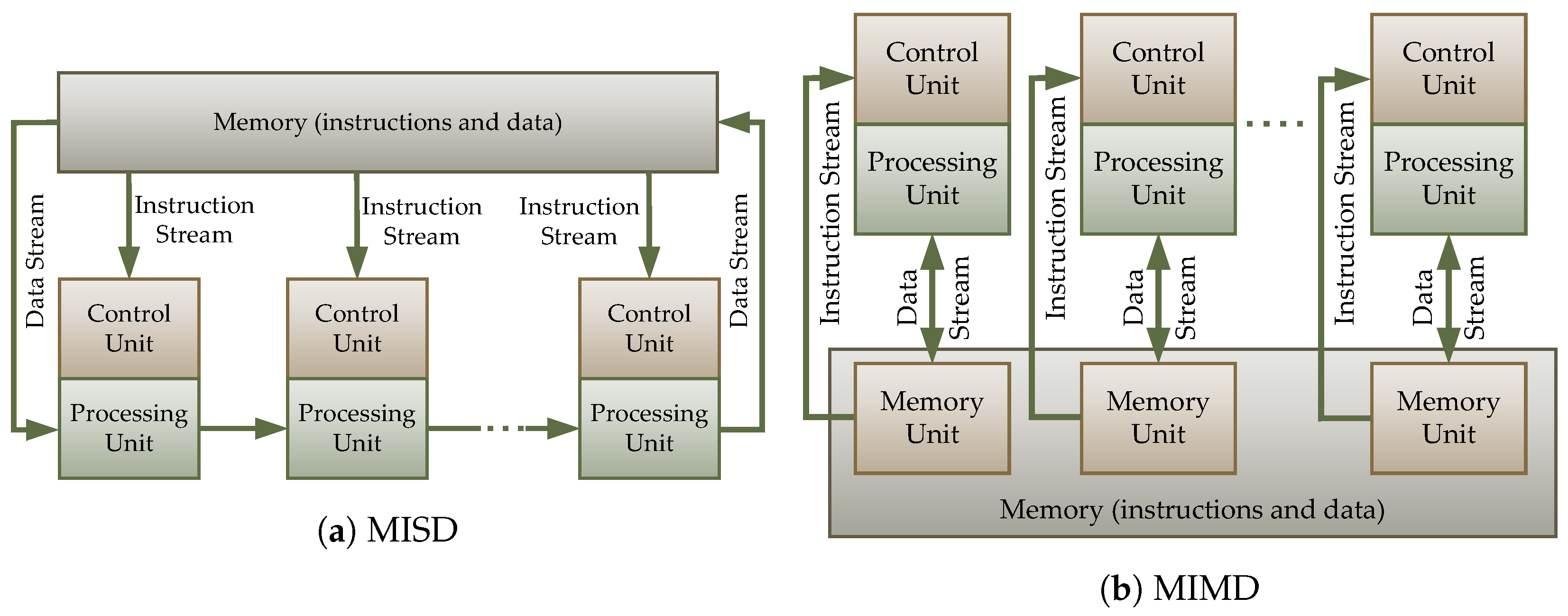
The P4 language is a programming language for the data plane in SDNs, meaning it is a programming language for SDN switches (although code written in P4 indirectly affects the control plane as well). Systems that use central processing units (CPUs) are Multi-Instruction stream Multidata stream (MIMD) systems. In contrast, data processing in programs written in the P4 language is of the Multi-Instruction stream Single-Data stream (MISD) type. The differences between these types are presented in
Figure 4. Programs and data processing in the P4 language closely resemble the operation of EasyChip network processors, which are divided into Task-Optimized Processors (TOP), specialized for performing specific tasks. To enhance the performance of network processors, individual tasks are parallelized. The TOP processors include the following:
TOPparser: processors responsible for extracting relevant operations from processed protocol units.
TOPsearch: processors optimized for data search, such as finding the next hop for a packet or the port number through which a specific MAC address is accessible.
TOPresolve: processors optimized for making decisions based on data provided by TOPSearch processors.
TOPmodify: processors optimized for modifying the structure of processed protocol units.
The P4 language specification not only includes the definition of command syntax, control instructions, built-in functions, and data structures but also outlines two types of architectures:
Portable NIC Architecture (PNA): This architecture describes the common capabilities of Network Interface Cards (NICs) in network devices that process and transmit packets between one or more network interface and the host system.
PSA: An architecture that details the common capabilities of network switches in terms of packet processing and forwarding.
PNA and PSA architectures facilitate the construction of any computer network (although they do not support the construction of access networks built on specific technologies like Passive Optical Networks (PONs)). They are used to build hosts and network nodes. Each architecture is associated with a defined platform, known as a target. This platform can range from general-purpose CPU, Field Programmable Gate Array (FPGA) devices, specialized Intel Tofino devices, or even Raspberry Pi boards. A significant difference among targets is their achievable performance, which varies from 10 Mbps (for Raspberry Pi devices) to 12 Tbps (when using Intel Tofino devices).
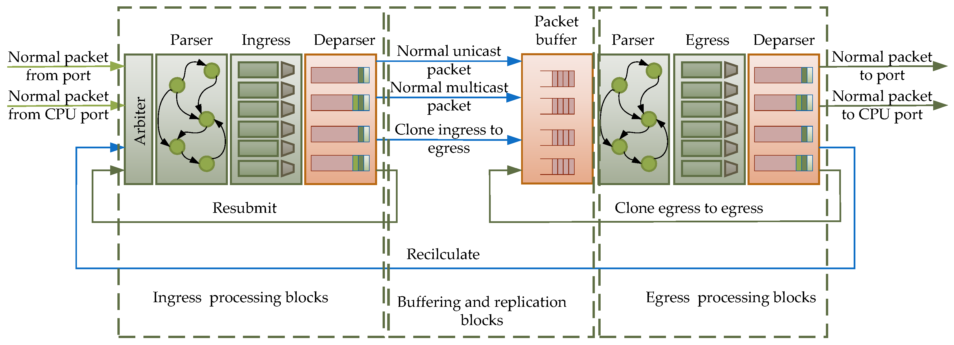
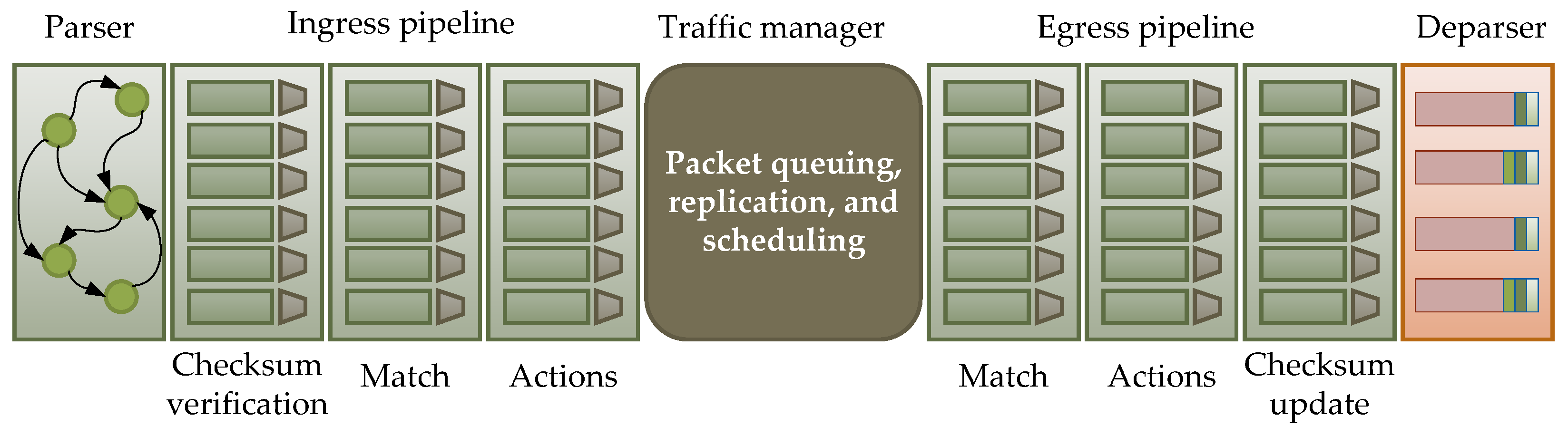
The general PSA architecture, as presented in
Figure 5, can be divided into three parts:
Ingress processing blocks;
Egress processing blocks;
A buffering and replication block.
Depending on the target, the number of blocks may be smaller. Not all platforms support the implementation of all processing stages, and implementing all blocks may reduce performance without significantly affecting achievable functionality. The parser blocks shown in the figure are used to extract data relevant to applications. Fields of constant length are straightforward to extract from headers. It is sufficient to define the header of interest by specifying the number of bits the particular field occupies, and individual fields can be retrieved with a single command. However, for variable-length fields, the process is more complex, especially since there are many methods for determining the length of header fields.
The last block in the packet path for both ingress and egress processing is the deparser block. Its task is reassembling the entire message. The data extracted by the parser must be reattached to the portion of the message that has not undergone processing. During deparsing, it is not necessary to add back the exact number of bits that were removed from the packet during the parsing process. This flexibility means that the outgoing packet from the node or NIC card can have not only altered data in the headers but also headers of varying lengths. It is also possible to encapsulate a protocol unit in another protocol.
6. Implementation
6.1. Environment Description
The P4 language specification defines the PSA architecture, which is illustrated in
Figure 5. This architecture can be considered a blueprint for P4 switch architecture, and it may vary depending on the device in which it is implemented. Several products on the market facilitate the creation of a data path using the P4 language. Among these are Intel’s Application-Specific Integrated Circuit (ASIC) devices, such as Tofino I, Tofino 2, and Tofino 3 [
45,
46,
47]. Additionally, there is the option to implement an SDN switch in FPGA circuits, for which the special NetFPGA SUME [
48], AMD Alveo [
49], or Intel [
50] platforms have been designed. The models defined for these products vary in the number of blocks on the packet processing path. A significant drawback of all these listed products is their cost. Therefore, in the proposed solution, it was decided to utilize a widely available and free option, the Mininet environment [
51], the main component of which is the SimpleSwitch software switch with V1 model implemented. Similar to SimpleSwitch, the V1 model also programmatically realizes the entire pipeline structure [
52,
53]. The V1 model is depicted in
Figure 6. Comparing it to the PSA architecture, shown in
Figure 5, differences are easy to identify. The parser block appears only once, at the switch’s input, whereas the deparser block is implemented at the switch’s output. In contrast, in the PSA architecture, both blocks appear in both the input and output pipelines. Additionally, in the input pipeline, there is also a checksum verification block (IP header), while the output pipeline includes a checksum update block. Both blocks must be utilized when implementing layer 3 functions, where the SDN switch acts as a router. The implementation uses external objects, which can be perceived as built-in functions. Their usage is limited to passing on function call parameters only; therefore, they are not presented in the following description of the implementation.
The V1 model architecture is is known as the target architecture for the P4 language. Each target architecture is supported by one or more targets. In the V1 model, the most commonly used target is the Behavioral Model v.2 (BMv2), which is implemented as a programmable switch in the Mininet environment for simulating computer network functions [
51,
54,
55]. It is important to note that not every target architecture may fully implement the P4 language, or the implementation might not fully comply with the language standard. This means that implementing the presented solution may require changes, even at the conceptual level, when used with a different target architecture. Before applying the presented solution to another target architecture, readers are encouraged to familiarize themselves with the BMv2 documentation and the documentation of the selected target architecture.
The BMv2 software switch and Mininet run on PC-class computers and are used for development, testing, and debugging new functionalities, both in the data plane and control plane. Although designed for use in a multithreaded environment, they exhibit significant limitations, affecting its performance. One such limitation is the use of only one thread to handle the input pipeline for all packets arriving at all ports of the switch, while output pipeline processing is, by default, carried out by four threads.
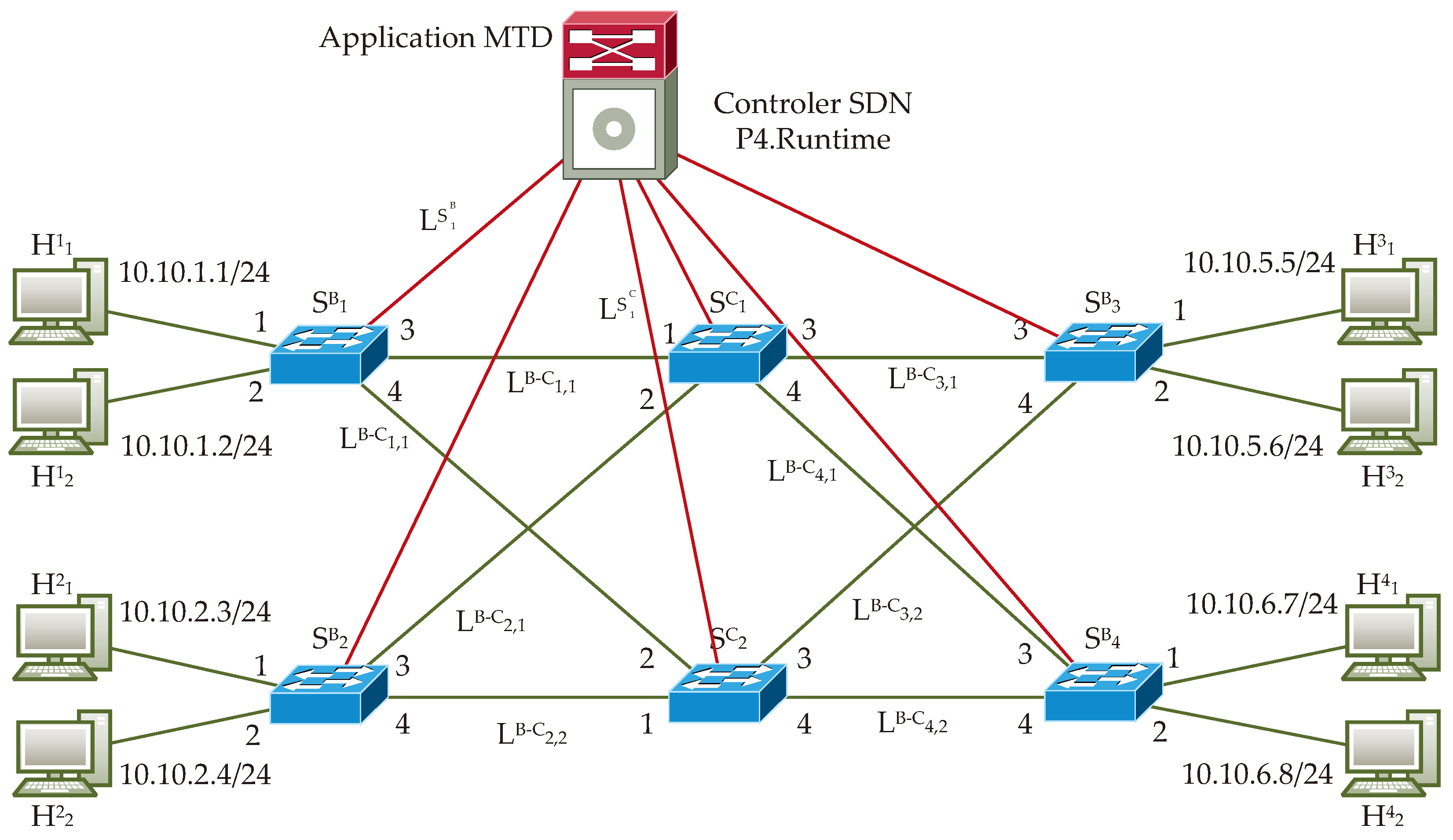
Figure 7 shows the structure of the network, which serves as the basis for preparing algorithms that implement the considered MTD technique. The presented structure includes four hosts and six switches. From the perspective of the functions performed by the switches, we can identify two types of switches:
Core switches, which are connected only to other switches;
Border switches, which have connections both to hosts and other switches.
All switches also have a connection to the SDN controller, which controls the operation of the entire network. These connections are only for the transmission of control information, such as entries to flow tables. To simplify the understanding of the algorithm, their participation is not further detailed here. Before describing the functions performed by both types of switches, let us introduce the concept of IP address generation. (Note: In the proposed implementation of the MTD technique, only IPv4 (IP version 4) addresses are used. However, the proposed mechanism can also be applied using IPv6 (IP version 6) addresses. The limitation to IPv4 was chosen to simplify the diagrams and enhance their comprehensibility.)
Definition 1. Define the generation of an IP address as a group of IP addresses that describes an entire computer network secured using MTD mechanisms. These addresses are exchanged in IP packets between border and core nodes, as well as among core nodes, in a specific state of the network.
Definition 2. Let us define a coherent network state as a state in which all border devices use only one logically consistent set of IP addresses.
The dynamic mutation of IP addresses in computer networks can proceed in two ways, synchronously and asynchronously. In synchronous mode, all network nodes should change the used group of IP addresses simultaneously. This necessitates the introduction of network synchronization mechanisms. An example of synchronous network parameter change can be observed in passive optical networks, where the Next-Generation Passive Optical Network 2 (NG-PON2) standard includes a mechanism for dynamically changing the wavelength used for data transmission between Optical Line Termination (OLT) and Optical Network Unit (ONU). To indicate the moment when the wavelength used by the ONU should change, a superframe counter is utilized, which is increased with each transmitted frame. Since only two devices (the OLT and one ONU) participate in synchronization, this mechanism works reliably. The structure of computer networks is much more complex than that of NG-PON2 networks, which only have point-to-multipoint connections. In computer networks, many nodes connect to many nodes, so achieving synchronization using the method used in NG-PON2 is virtually impossible. Another method of achieving synchronization is the use of synchronous ethernet, described in [
56]. Synchronous ethernet does not address the issue of changing IP addresses, which would not affect established TCP connections. Synchronous ethernet only offers synchronization at the bit or byte level. A problem arises if IP address changes occur during the transmission of an ethernet frame: a node might begin transmitting an ethernet frame containing an IP packet with a specific IP address, and, if IP addresses in the network change during transmission, the IP addresses upon reception could fall outside the correct address space. While it might be feasible to introduce a protective period to complete the transmission of the started frames, determining the precise duration of this protective period would be challenging. This duration would need to account for frame propagation times, their processing in nodes, etc., for any pair of nodes. It is possible to assume a sufficiently long protective time, but this would likely result in a deterioration in service quality (reduced network throughput, extended transmission time). Furthermore, periodic breaks in data transmission would be a signal to an observer that some change in the network structure is taking place. To avoid problems with synchronous mode, the proposed solution uses an asynchronous method. In this approach, network nodes are allowed to use two generations of IP addresses—old and new—for a certain period. To make this possible, the following requirements must be met: Before using the new generation of IP addresses, it is necessary to distribute all necessary entries related to the new generation in the flow tables in all network nodes, i.e., in both border and core nodes. The start of using the new generation of IP addresses occurs when the SDN controller introduces information about the new generation into the appropriate flow table in at least one network node. In this scenario, the process of changing generations throughout the entire network lasts for a specified period. Unlike the wavelength-changing methods in NG-PON2 networks, it is impossible to precisely predict when information about the next generation of IP addresses will reach the switch. The change in the current generation in the switch can occur in two way: either by an entry into the flow table or by the switch detecting the new generation by the switch during packet processing. This necessitates storing information about the generation not only in the flow table but also in a structure the data plane’s program code can modify. This structure could be a register. Each target of the P4 language offers several registers that can be utilized in the program code. One feature of registers is their ability to store data between subsequent packet processing events, meaning that changes introduced in the register during the processing of packet
n are available during the processing of packet
. Each switch, when detecting a new generation of IP addresses, modifies the contents of the register. If the contents of the register contain a newer (different) generation, it sends a message to the SDN controller. The removal of entries related to the outdated generation of IP addresses from flow tables is possible when the network reaches a specific state, i.e., when each switch in the network receives an entry from the SDN controller to the appropriate flow table about the new version or detects the new generation during packet processing and successfully informs the SDN controller about it. Immediately after removing outdated (old) entries from the flow tables, the network should be prepared for the use of the next generation of IP addresses by delivering new entries to all switches. This preparation involves an algorithm for controlling the core switch. Core switches aggregate traffic from many border switches. Their functions are limited to determining to which port of the switch the packet should be sent.
6.2. Lossless Dynamic IP Address Mutation Algorithms
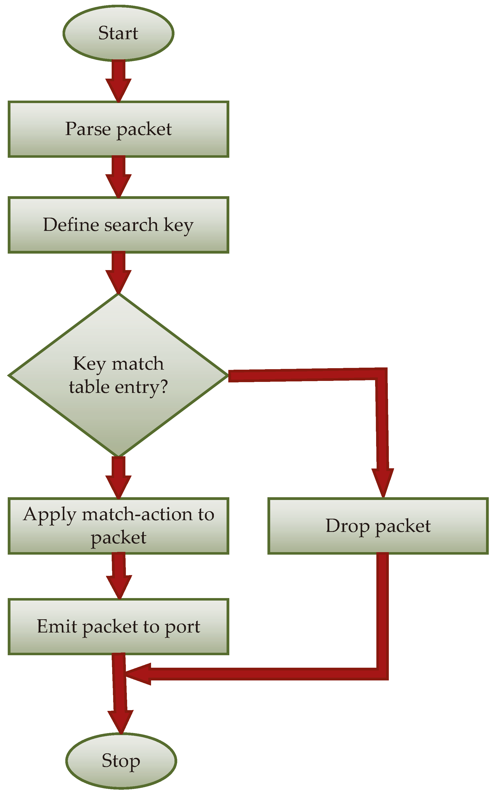
As mentioned in the previous subsection, the network comprises two types of network elements: core switches and border switches. In the proposed solution, both types of switches implement a different algorithm. For core switches, the algorithm (illustrated in
Figure 8 and, as pseudocode, in Algorithm 1) is confined to directing the packet to the appropriate output interface or deleting the packet in the absence of a corresponding entry. Since the entire network is assumed to use IP addresses assigned by the SDN controller, the appearance of a packet directed to an IP address not within the group of addresses assigned to hosts can, at most, activate functions that inform the controller about such an event. It is crucial that before adopting a new generation of IP addresses, the flow tables of all core switches contain all the necessary entries related to that generation. Core switches do not modify packet headers, except for the standard operation of the IP protocol, namely, the decrease in the Time-To-Live (TTL) field. Since this is a standard operation, it is not included in
Figure 8 or Algorithm 1. The processing algorithm us presented in two ways, as a diagram and as pseudocode, enabling readers to more easily grasp the operation of the proposed method. While the diagram does not indicate all the keys used in searching the flow tables, it significantly aids in analyzing the algorithm.
| Algorithm 1: Packet processing algorithm in core switch. |
![Electronics 13 00918 i001]() |
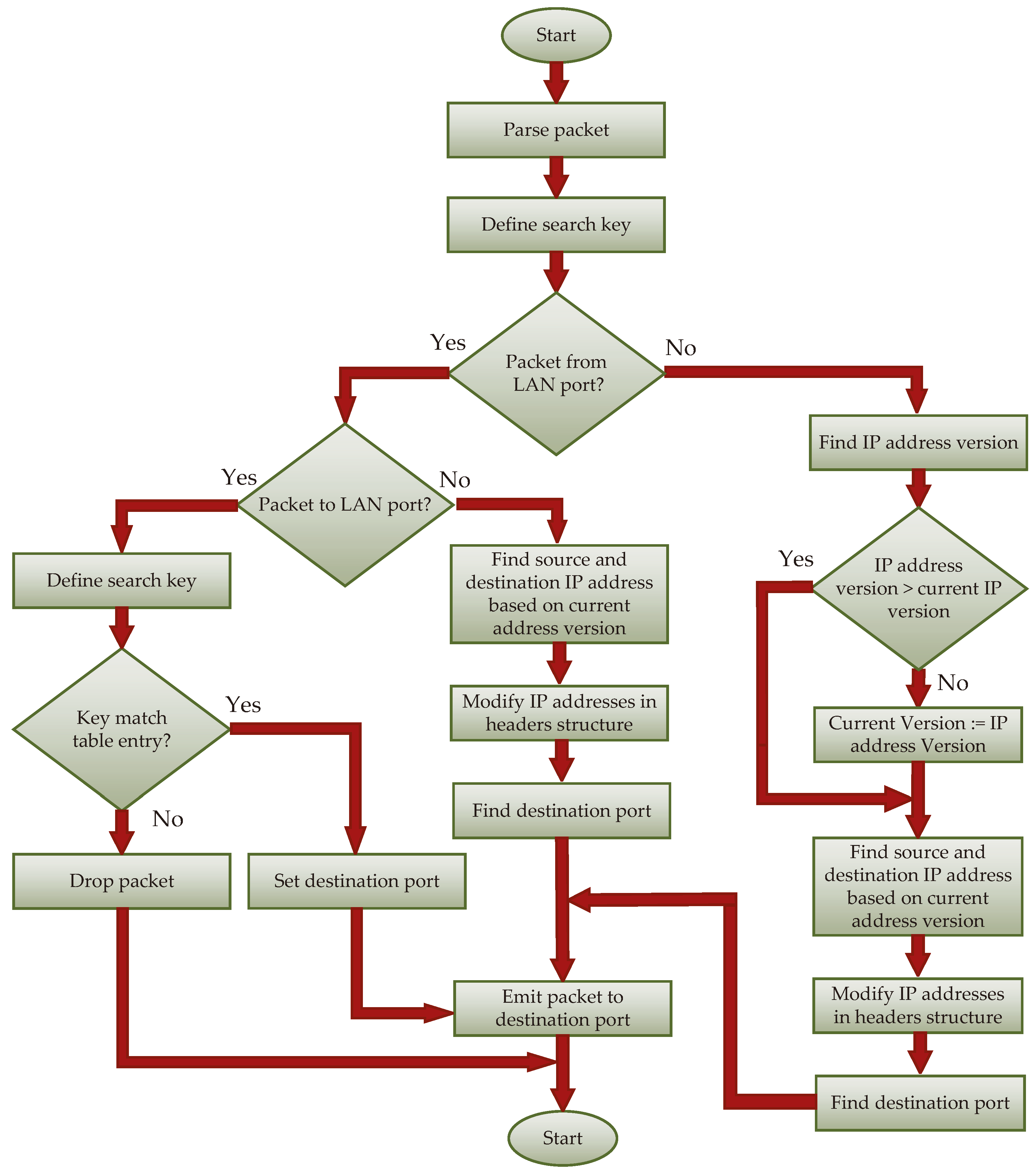
In the case of border switches, whose algorithms are illustrated in
Figure 9 and Algorithm 2, the processing process includes a larger number of conditional instructions. The common step in all paths of the algorithm is determining the input interface and the interface through which the packet must be sent. The number of the input interface is already provided in the parser block as standard metadata. The number of the output interface can only be determined in the ingress match block after searching the appropriate flow table. Input and output interfaces can be categorized into local and core interfaces. Based on the pair <input interface, output interface>, we can identify four packet processing processes:
<local, local>: In this mode, the packet is directed to a specific local interface. The only modification that may occur is updating the TTL field and the checksum field of the IP header.
<local, core>: In this scenario, it is necessary to modify both the source and destination IP addresses, which are contained in the respective flow tables. The search involves IP addresses and a value representing the current generation, which can be stored in a separate flow table or register (register is a special type of data in the P4 language, and a variable, uniquely retains a value determined during the processing of the previous packet).
<core, local>: The scenario very similar to the <local, core> case. The modification of the IP addresses to those used in the local network is also required. To find the IP addresses that will replace the IP addresses present in the packet headers, only the IP addresses from the header are utilized. The result of the search also returns the generation of IP addresses. If the searched generation is newer than the current generation, it indicates that the system has started using a new generation. In such a case, modifying the generation table or register and sending a message to the SDN controller once is necessary.
<core, core>: This scenario, not included in the diagrams to avoid further expanding them, is possible to implement. The operation mirrors that of the <local, local> case, albeit with different flow tables.
| Algorithm 2: Packet processing algorithm in border switch. |
![Electronics 13 00918 i002]() |
Implementing the proposed mechanism in traditional computer networks is practically impossible. Routers make packet routing decisions based on the entries in the routing table, the contents of which are supplied by specific routing protocols. Changing the contents of routing tables is possible, for example, by using static entries that would be supplied through the Representational State Transfer Configuration (RESTCONF) protocol [
57]. However, such a procedure would be quite time consuming. This means that services provided by networks would be temporarily unavailable for a certain period, which, in modern networks with throughput expressed in tens of GB/s, is unacceptable. Moreover, changing the IP addresses of router interfaces forces the change in addresses for all hosts connected to the router (directly or via layer 2 switches). This requirement could be addressed by using the DHCP protocol. However, introducing another traditional mechanism would further extend the service unavailability. Even using NAT functions would not solve the problem due to functional limitations (changing IP addresses affects existing TCP sessions, problems with UDP protocol handling, the need for port forwarding). Implementing such a solution in a traditional computer network, from the network administrator’s perspective, would be an unimaginable endeavor.
7. Performance Evaluation
7.1. Convergence Time
To conduct the optimization process and assess the effectiveness of the solution, it is necessary to determine the system’s convergence time, meaning the time required for all switches to exclusively use addresses from the current generation (this also includes the IP addresses of packets in the network interface buffers and packet memories). Two scenarios should be considered.
Scenario I: All modification are introduced simultaneously by in all border switches. In this scenario, the convergence time is determined by two components:
For formal notation, let us introduce designations for the active elements (such as core and border switches, hosts, and the SDN controller) and passive elements, namely, links. Let
denote the
ith core switch. Similarly, let us denote the
jth border switch as
. Host number
k, connected to
, is denoted as
. The SDN controller, having only one instance, is simply denoted as
. The link between
and
(i.e., the link between the
th and
th core switches) is denoted as
, the link between
and
(i.e., the link between the
th and
th border switches) is denoted as
, while the link between
and
is denoted as
. The link between the controller and
or
is denoted as
or
, respectively.
Figure 7 illustrates these network elements along with their designations.
Additionally, let us introduce the notation of the function , which returns the time value in which an IP packet is in element (which can be either an active and a passive element) x.
The first component of convergence time is defined by the following equation:
where
(
) is the time of generation, buffering, and sending a message in the SDN controller on the interface to
(
);
is the time of receiving, verifying correctness, buffering, and updating the flow table in switch
; and
is the propagation time between
and
. Assuming that
sends almost identical messages to all
(only differing in IP and MAC addresses), that all interfaces of
are identical, and that all
switches are identical, Equation (
1) can be simplified to
This means that the time of the first component is equal to the time of updating the flow table in the border switch most distant from
.
The second component of the convergence time is equal to the longest duration for an IP packet to pass between two edge switches. Excluding situations where a packet may be buffered in switches (due to temporary disconnection/switching of the network link), unusually long packet handling in the switch, etc., this time can be calculated from
where
is the time of generating and sending an IP packet from
, while
is the time of receiving and processing an IP packet in
. The times
and
are the propagation times on the links connecting border switches to core switches. The time
is the time of receiving the packet, processing it (finding the route for the packet, modifying IP header fields), and sending it to the next switch. The time
is the propagation time between two core switches. Similar to
, we can assume that all active elements are identical, so Formula (
3) can be simplified to
where
c is the number of core switches located on the path between two border switches. The signal in a fiber optic link is transmitted at the speed of light (
m/s), which means that sending a frame over a distance of 1 km takes 3.3
. Assuming that the protected network is located in a limited area, where the length of links between core switches is similar and does not exceed the length
(e.g., 1 km), Formula (
4) can be simplified to
Considering all time components, the convergence time in scenario I is calculated as
Scenario II: In this scenario, it is assumed that the SDN controller cannot send information about the change in IP address generation to all switches simultaneously. Instead, the data exchange operation follows a sequential algorithm, where the controller only proceeds to modify the flow tables in the next switch after receiving confirmation of the modification’s completion from the currently modified switch. The controller can proceed to modify the flow tables in the next switch only after receiving confirmation of the completion of the modification from the switch currently being modified. According to Algorithm 2, the change in IP address generation, enforced by messages from the SDN controller, can be supplemented by propagating information about the new generation through the exchange of IP packets in the data plane. It is worth noting a potential Scenario III, where the SDN controller informs only one switch about the generation change, and the other switches adjust the generation of IP addresses based on packet exchanges in the data plane. This approach has a significant limitation: if a given edge switch does not receive IP packets with addresses from the new generation—or receives no IP packets at all—it will continue using the previous generation of IP addresses. While using generation propagation in the data plane can speed up the generation change in individual switches, informing all switches through the SDN controller is necessary to achieve a converged state.
In such a case, the convergence time in scenario II (denoted as
) is equal to the sum of the message transfer times between the SDN controller and all SDN switches, as well as the longest packet transmission time between two border switches.
is given by
where
c is the number of core switches, and
b is the number of border switches.
7.2. Numerical Experiment
In
Section 7.1, considerations regarding the convergence time of the system were presented, which is the time required for all switches to use only the set of IP addresses belonging to a given generation.
Table 1 presents the time characteristics of the SDN elements that are necessary to calculate the convergence times in scenarios I and II.
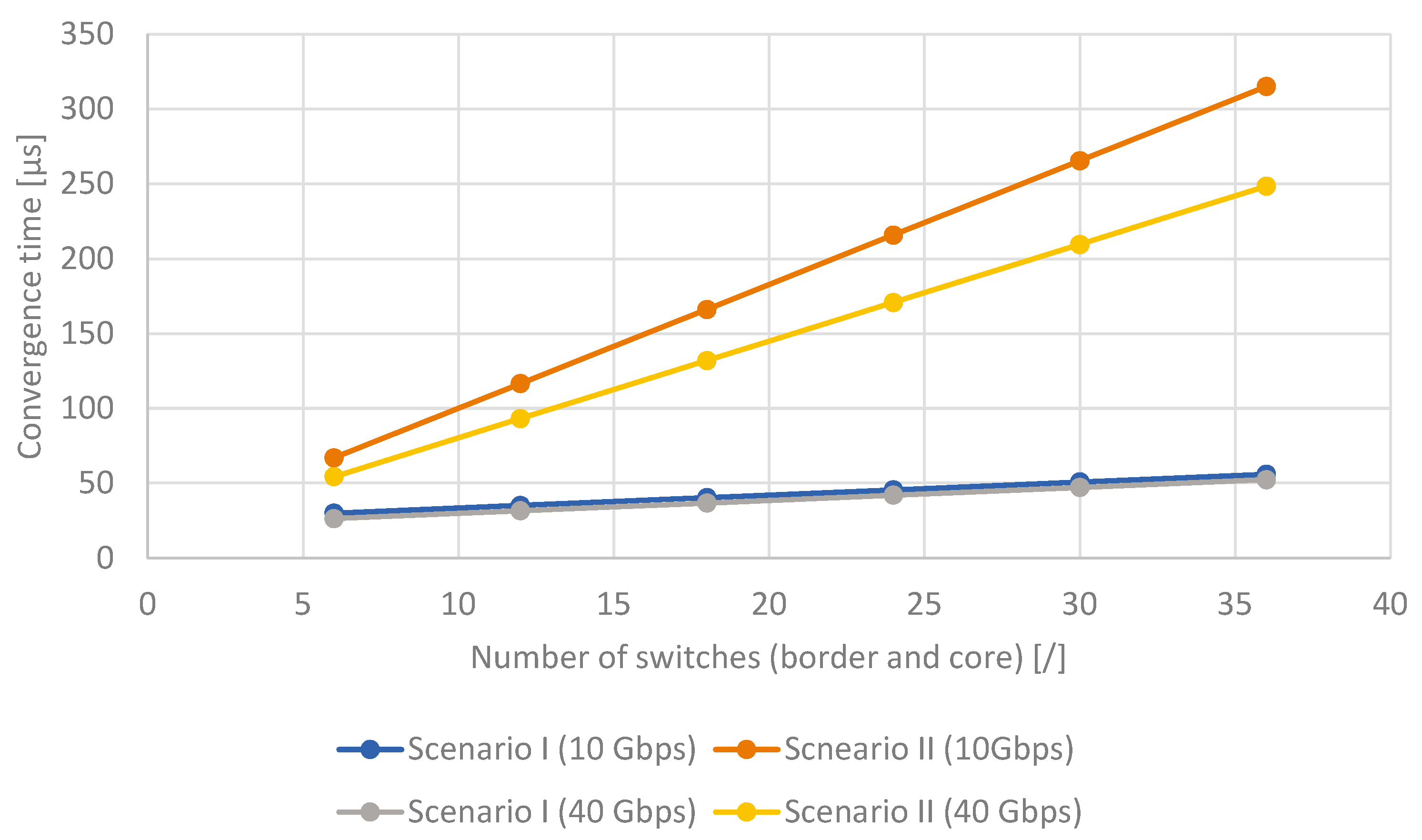
Figure 10 compares the convergence times of networks using scenarios I and II for different link bandwidths (10 Gbps and 40 Gbps) and different numbers of switches. The chart shows the total number of border and core switches. It was assumed that the ratio of core to border switches was 1:5. As can be observed, the convergence time did not exceed
s.
In order to assess the performance of the proposed solution, we needed to consider the time required to prepare the switches for the application of IP addresses of the next generation. For all switches to be able to use the new generation, the SDN switch must update the flow tables in all switches. According to Algorithms 1 and 2, it is necessary to modify the tables:
in core switches, which contains entries, where h is the number of hosts in the supported network,
in border switches, which contains h entries;
in border switches, which also contains h entries.
The time required to modify flow tables is dependent on the amount of modifying data, which in turn depends on the number of commands and parameters contained in the packet [
61]. Modifying commands are transmitted between the SDN controller and the switches as text, formatted according to JSON notation. The number of bytes in such a command depends on the number of characters. However, it should be noted that determining the exact number is impossible, as, for example, an IP address in version 4 is made up of 4 bytes, but in JSON notation, it can occupy from 7 bytes (e.g., 1.1.1.1) to 15 bytes (e.g., 192.168.136.200). The names of tables and the functions called also affect the number of characters transmitted in a single command. For simplicity, let us assume that one command is 60 bytes (characters) long.
Let us determine the time necessary to update a table involving the exchange of
R rows. Based on the research results presented in [
61], we can assume that updating 25 entries (according to the assumption, the modifying command is 60 bytes long) in a table takes approximately 90 ms. Let
denote the time needed to modify
R rows in the flow table.
can be determined using
Taking into account the modification times presented in [
61], Formula (
8) can be simplified to the form
Meanwhile, the time required to modify tables (denoted as
) in all the switches of the considered network, which is composed of
h hosts connected to each border switch,
b border switches, and
c core switches, is
In
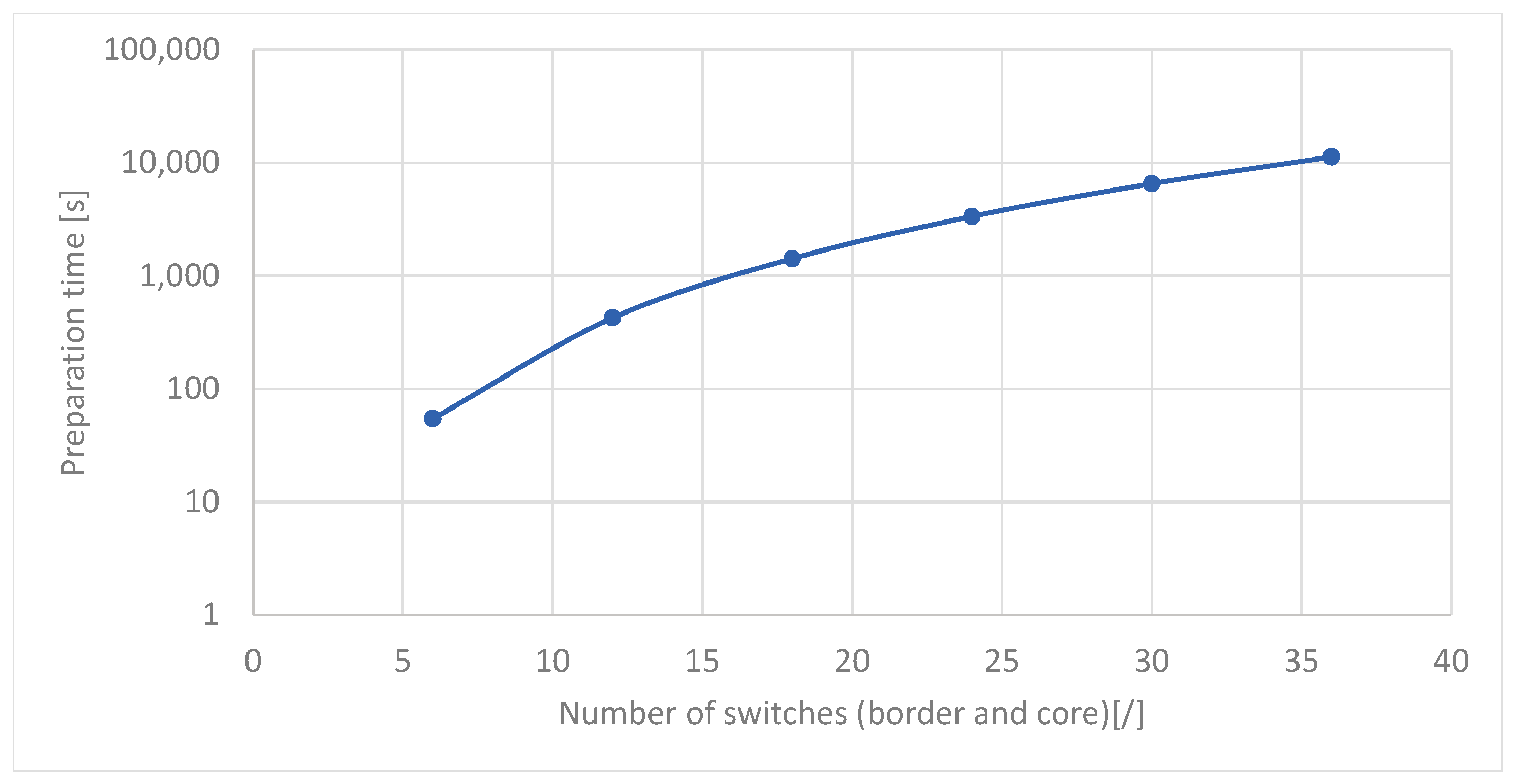
Figure 11, the changes in the time necessary for updating the flow tables in all network switches are presented. It was assumed that each border switch was connected to 24 hosts. Meanwhile, the ratio of the number of core hosts to the number of border switches was 1:5 (similar to the comparison presented in
Figure 10). As can be observed, the time required to prepare the switches for the change in IP address generation increases exponentially with the increase in the number of switches (and consequently with the increase in the number of hosts) from a few seconds to 3 h. It should be noted that this solution was not optimized in this respect.
8. Conclusions and Future Works
Our civilization’s dependence on IT solutions, as well as the geopolitical situation, requires new research tasks and the delivery of new solutions in the field of cybersecurity. This article proposed a new approach to one of the MTD technologies using IP address mutation. We used an SDN and programming in the P4 language, which adds a new dimension to shaping the functionality of the data plane. In research on the effectiveness of MTD mechanisms, studies have rarely been conducted on the impact of the applied techniques on the quality of services provided to users [
62]. The use of MTD techniques can lead to disruptions in service availability [
7,
8] or, as is the case with IP address mutation mechanisms that utilize DHCP or DNS services, to connection interruptions [
9]. The presented solution is distinguished from other proposed solutions by its ability to maintain the continuity of services. By applying the described solution, any interruption in TCP connections is avoided, which is significant for networks operating at bandwidths above 10 Gbps. The inability to transmit data even for a few seconds can result in significant data loss. Another important advantage of the proposed solution is its flexibility. This solution does not require modifications to the operation of services such as DHCP or DNS and thus is not limited by their functioning.
Performance analysis of the proposed solution indicated that with an increasing number of hosts in the network, the permissible speed of IP address mutation drastically decreases. This is due to the use of an extremely simple mutation algorithm, in which IP addresses were mutated in a completely random manner at each step, necessitating the modification of entire flow tables. Such an algorithm is not optimal. In further work, researchers can attempt to optimize the mutation algorithm, in which IP addresses will be changed only for a portion of the hosts in subsequent mutations. Another scenario to consider is mutating addresses only for devices providing critical services. Considering the flexibility of implementation provided by the P4 language, further studies can introduce additional mutation scenarios.
Another direction for future research involves conducting a detailed analysis of the proposed solution. The Mininet environment used in this study only allowed for the confirmation of the proposed solution’s functionality. Since preparing a sufficiently large research environment, where programmable SDN switches would be utilized, is an extremely difficult and costly endeavor, there is a plan to develop an appropriate simulator in the OMNET++ environment.


