Article

A Novel Alternating μ-Law Companding Algorithm for PAPR Reduction in OFDM Systems

1
Department of Electronic Engineering, National Formosa University, Yunlin 632301, Taiwan
2
Department of Information and Communication Engineering, Chaoyang University of Technology, Taichung 413310, Taiwan
*
Authors to whom correspondence should be addressed.
Electronics 2024, 13(4), 694; https://doi.org/10.3390/electronics13040694
Submission received: 30 November 2023 / Revised: 1 February 2024 / Accepted: 6 February 2024 / Published: 8 February 2024
(This article belongs to the Topic Electronic Communications, IOT and Big Data)

Abstract

:
Orthogonal frequency division multiplexing (OFDM) inherits multi-carrier systems’ inevitable high peak-to-average power ratio (PAPR) problem. In this paper, a novel alternating companding technique is proposed to combat the harassment of high PAPR. The sequential μ -law companding (SULC) and a tone with a lower PAPR result in only partial tones needing companding. The SULC scheme’s PAPR and bit error rate (BER) performance has been balanced and improved. However, the computational complexity is still too high to be implemented. Therefore, this study sorted the transmission signals according to their amplitudes. Then, all the tones are divided into two groups by estimating the rough companding amount (around 54% of the subcarriers), using traditional parallel companding for the first group and the other group only by partial μ -law companding. This alternating μ -law companding (AULC) is proposed to improve the PAPR performance and simultaneously reduce complexity. Simulation results show that the proposed AULC method appreciably reduces the PAPR by about 5 dB (around 45%) compared with the original μ -law at complementary cumulative distribution function (CCDF) equal to 10 4 . Moreover, it only requires a moderate complexity to outperform the other companding schemes without sacrificing the BER performance in the OFDM systems.

1. Introduction

Since the development of wireless communication systems, human needs for increased convenience and improved daily life have increased significantly from voice messages to multimedia. This has also made the Internet of Things (IoT) [1,2,3], industrial automation, and telemedicine popular research areas. Of course, they need efficient power control, massive data transmission, increasing connection numbers, high spectral efficiency demands, and other requirements. Therefore, it is highly urgent to increase the data emitted and transmission quality and improve spectrum utilization efficiency; simultaneously, IoTs have become one of the critical developments in fifth-generation (5G) wireless communications [4,5].
In light of this, it is inevitable to evolve from single-carrier to multi-carrier technology [6]. Also, among multi-carrier technologies, orthogonal frequency division multiplexing (OFDM) possesses the characteristic of overlapping and mutually orthogonal subcarriers, thereby enhancing spectral efficiency (SE), prompting the robustness of resistance against multipath interference and inter-symbol interference (ISI) [7], and OFDM has been the most popular and mature vital technology in advanced wireless communication systems [8,9,10,11]. Unfortunately, OFDM bears the inherent nature of a multi-carrier system; therefore, the issue of peak-to-average power ratio (PAPR) is inevitable. Higher PAPR can lead to nonlinear distortion when transmitting signals through amplifiers. Thus, pursuing an effective method to reduce PAPR and complexity without sacrificing bit error rate (BER) performance in OFDM systems has become an urgent research issue.
At present, many various well-known techniques have been put forward to reduce PAPR in OFDM systems [12,13,14], such as clipping, nonlinear companding transform (NCT), partial transmit sequence (PTS), selective mapping (SLM), tone injection (TI), tone reservation (TR), etc. Among these techniques, clipping [15,16] is the simplest; however, the clipped signal is prone to clipping noise, and the threshold value of clipping is challenging to select and store, resulting in a significant drop in BER performance [17]. In terms of PTS technology [18,19,20,21], after dividing the frequency domain signal into clusters, each cluster is through an inverse fast Fourier transform (IFFT) and is multiplied by a rotation factor to change its phase. Then, all the clusters are summed up and combined into an output signal. To find the optimal PAPR signal, the rotation factor will be chosen through a massive search. What is more troublesome is that the PTS technology suffers from a fatal drawback that makes it difficult to recover the signal at the receiver. While the SLM scheme [22,23,24,25] multiplies the frequency domain signals by different rotation factor vectors and produces multiple candidate signals through IFFT, the minimum PAPR signal is selected for transmission. In TI technology [26,27], various expansion methods embed the extra constellation points to the original constellation. This provides more choices and diversity for each signal, thereby mapping the constellation signals to the equivalent locations in the constellation and achieving the objective of reducing PAPR. As for the traditional TR method [28,29,30], this method selects the appropriate peak countervail signal according to different lengths and positions and then blends it into the transmission signal to reduce PAPR.
There are two standard methods for nonlinear companding transform schemes: μ -law and A-law [31]. This article will specifically focus on the μ -law method. In [31], Proakis et al. described the principle of companding, which involves compressing the larger signals at the transmission end to reduce the signal’s dynamic range. At the receiving end, expansion is employed to restore the signal. Furthermore, Proakis and others also proposed the μ -law companding equation, which aims to reduce PAPR by compressing large-amplitude signals and enhancing small-amplitude signals. In addition, Wang et al. proposed a similar μ -law companding formula [32]. This companding method amplifies small-amplitude signals while large-amplitude signals remain unchanged. It improves the companding performance compared to the μ -law companding transform proposed in [31], effectively reducing more PAPR but sacrificing more BER performance. For convenience, in further discussion, we will refer to the μ -law companding scheme proposed in [31] as the original μ -law companding method and the μ -law companding scheme proposed in [32] as the modified μ -law companding method. Moreover, the improved two- μ s companding (ITM) [33] proposed by Nazar Ali et al. is based on the algorithm extended by modified μ -law [32,34,35]. Through two different μ parameters, normalized factor K, and appropriate threshold points, it can obtain better PAPR performance than the modified μ -law. Also, Malini et al. use the ITM algorithm to add the discrete cosine transform (DCT) operation [36], resulting in better PAPR reduction than ITM. Unfortunately, the BER performance of these two methods can be expected to drop significantly under high-order modulation, making them difficult to apply in environments with high data transmission volumes. Additionally, Ramtej et al. proposed an improvement scheme in [37] based on the modified μ -law. This scheme achieves the purpose of maintaining average power through the proposed companding equation. However, they cannot meet reduced PAPR, small BER, and suitable complexity simultaneously. Moreover, not much literature discusses the μ parameter. Therefore, we define an efficiently balanced parameter, η , to pre-estimate a more appropriate μ value and use the SULC scheme to overcome the above issues. Furthermore, we simultaneously proposed a novel AULC scheme to reduce the complexity and maintain BER performance compared to the SULC.
Under conducting a trade-off between PAPR and BER, we utilize the Monte Carlo method to analyze the impact of μ parameter values on performance through probability and statistics estimate procedures. By this, we choose the optimal μ parameter and apply it to this research methodology. Next, we sequentially compand the transmitted signal and compare it with the original OFDM signal to pick that with a lower PAPR for transmission. The AULC scheme sorts the transmission signals according to their amplitudes, estimates the rough companding amount through Monte Carlo, processes parallel companding the same as the original μ -law by the estimated proportion and then performs partial companding on the remaining components, which can further reduce the complexity. In other words, it divides the total tones into two groups and uses traditional parallel companding for the first group and partial SULC for the second group to reduce complexity and refine PAPR performance. It is worth noting that this study applies side information to the receiver to maintain BER performance. Although the side information may increase the transmission bandwidth required, this effect should be alleviated through data compression, which is beyond the scope of this article.
The rest of this paper is organized as follows. In Section 2, we introduce the system model. Section 3 reviews previous well-known techniques. Section 4 illustrates our proposed methods. Section 5 analyzes the simulation results and complexity to validate and discuss comparing our proposed schemes with other previous works. Finally, Section 6 concludes the article.

2. System Model

In this paper, uppercase and lowercase symbols denote the signal of the frequency domain and time domain, respectively. Also, the boldface indicates vectors.

2.1. Orthogonal Frequency Division Multiplexing (OFDM) Systems

Figure 1 shows the basic architecture of the OFDM systems. First, the input data are modulated by quadrature amplitude modulation (QAM); then, serial signals are generated and converted into parallel signals X = [ X 0 , X 1 , , X N 1 ] T . Turning X into an OFDM signal x = [ x 0 , x 1 , , x N 1 ] T by IFFT, the nth tone of x can be denoted by [6]:
x [ n ] = 1 N k = 0 N 1 X [ k ] e j 2 π k n N , 0 n N 1 ,
where X [ k ] is the kth tone of the QAM signal, and N denotes the number of subcarriers.
Finally, the parallel OFDM signals are transformed into serial and transmitted through a digital-to-analog converter (D/A converter) and a high-power amplifier (HPA) into the channel with additive white Gaussian noise (AWGN) that conforms independent and identically distributed (i.i.d.). Next, we generate the output signal r as
r = H x h + n ,
where H is the channel matrix, x h is the signal after passing through HPA, and n is the noise. Then, the signal r is sequentially restored to the original signal at the receiving end by the analog-to-digital converter (A/D converter), fast Fourier transform (FFT), and QAM de-modulator.

2.2. Peak-to-Average Power Ratio (PAPR) Definition

The PAPR of an OFDM signal is defined as the ratio of the maximum peak power to the average power, which the following function can express [6]:
P A P R = max 0 n N 1 | x [ n ] | 2 E | x | 2 ,
where max [ · ] and E [ · ] denote the largest value in a certain range and the expectation operator, respectively.
The performance of PAPR reduction techniques is generally evaluated using the complementary cumulative distribution function (CCDF). CCDF is defined as the probability of PAPR exceeding the α . This paper uses the following formula to evaluate PAPR [38]:
C C D F = P ( P A P R > α ) = 1 ( 1 e α ) N ,
α is the threshold.

3. Related Work

In this section, we will briefly introduce and discuss original μ -law companding to enhance the article’s readability and speed understanding.
As shown in Figure 2, it applies an μ -law companding algorithm to the OFDM systems. Using the OFDM signal through the μ -law algorithm to reduce PAPR, we can present by y  as below [31]:
y = s g n ( x ) log ( 1 + μ | x | ) log ( 1 + μ ) ,
where x is the OFDM signal, μ is a positive number, and s g n ( · ) is a sign function, as shown in Figure 3, that can be defined as
s g n ( x ) = x | x | x 0 0 x = 0 .
Thus, we can turn Equation (5) to another form as
y = x | x | · l o g ( 1 + μ | x | ) l o g ( 1 + μ ) ,
then, moving the item x to the left side of Equation (7), we can obtain the ratio between y and x as
y x = 1 | x | · l o g ( 1 + μ | x | ) l o g ( 1 + μ ) .
To make the equation easy to read, we denote y [ n ] x [ n ] as λ . Next, we will consider x [ n ] 0 and discuss three cases, such as λ = 1 , λ > 1 , and λ < 1 .
case 1.
λ = 1 :
Because λ is equal to 1, we can infer that | x [ n ] | is identical to l o g ( 1 + μ | x [ n ] | ) l o g ( 1 + μ ) . Then, we will obtain the identity equation as follows:
l o g ( 1 + μ | x [ n ] | ) l o g ( 1 + μ ) = | x [ n ] | .
Now, we use a graphical method to find the x [ n ] solution in Equation (9), as shown in Figure 4. No matter how μ changes, we can see that x [ n ] = 1 as λ is 1.
case 2.
λ > 1 :
In terms of λ > 1 , 1 | x [ n ] | · l o g ( 1 + μ | x [ n ] | ) l o g ( 1 + μ ) > 1 , then Equation (9) can be rewritten as
l o g ( 1 + μ | x [ n ] | ) l o g ( 1 + μ ) > | x [ n ] | .
Similar to case 1, from Figure 4, we can find the interval of x [ n ] that satisfies the inequality Equation (10). Therefore, when λ > 1 , the x [ n ] will be expressed as
0 < x [ n ] < 1 .
case 3.
λ < 1 :
Finally, when λ < 1 , the inequality Equation (10) will become 1 | x [ n ] | · l o g ( 1 + μ | x [ n ] | ) l o g ( 1 + μ ) < 1 , which is equivalent to:
l o g ( 1 + μ | x [ n ] | ) l o g ( 1 + μ ) < | x [ n ] | .
Looking at Figure 4 again, Equation (12) can be satisfied as long as x [ n ] > 1 . Hence, when λ < 1 , then we will obtain the following:
x [ n ] > 1 .
As to the above investigation, for x [ n ] < 0 , we can infer that when λ = 1 :
x [ n ] = 1 ,
λ > 1 :
1 < x [ n ] < 0 ,
λ < 1 :
x [ n ] < 1 .
From the above-mentioned, we can see that when x [ n ] ’s absolute value is less than 1, the μ -law equation will expand signals. On the contrary, the equation will compress signals.
As for the receiving end, the signal can be recovered using the following function:
y ˜ = s g n ( r ) ( 1 + μ ) | r | 1 μ ,
where y ˜ is the signal of the inverse of μ -law, and r is the received signal through the channel. It is worth mentioning that the original μ -law scheme is a vector-based parallel companding method.

4. Proposed Scheme

Behind understanding the characteristics of the original μ -law, as it applies to reduce the PAPR, we know that the μ parameter will affect the performance of PAPR and BER simultaneously. Hence, the choice of μ parameter is an essential issue. As the μ increases, PAPR will decrease, but the BER performance will be sacrificed. Therefore, we referred to a possessive selectivity scheme with a component-wise mechanic to alleviate the conflict between PAPR and BER in the original vector-based parallel μ -law method. We name it the SULC scheme. Although this scheme’s PAPR and BER performance is well balanced and improved, its complexity still has room for improvement. Therefore, we proposed a novel AULC scheme to reduce the complexity further.
For a while now, there has been no precise rule for selecting the value of the μ parameter in the μ -law companding schemes. To obtain a reasonable μ parameter estimate for PAPR and BER performance balancing, we utilize the Monte Carlo method and the numerical analysis of the proposed approach to arrive. Moreover, it is proved by experiments that our proposed schemes can reduce the PAPR significantly and maintain the performance of BER at a small and wise choice μ parameter value. In this study, we made a trade-off between PAPR and BER; then, we chose the optimal value of the μ parameter as 3 and applied it to our experiments in this article. Furthermore, we define a more obvious balance parameter, η , to evaluate and verify this best choice. The following will describe the SULC and the proposed AULC algorithms.

4.1. Sequential μ -Law Companding Method (SULC)

Herein, we will describe the SULC methodology and outline the procedural steps in Algorithm 1. These consist of two stages.
In the first stage: (initial stage)
 
Initially, assign the input signal x to x by the following method:
x = x 0 , x 1 , , x N 1 ,
where x = x 0 , x 1 , , x N 1 is the OFDM signal. Next, set the index value n to zero and assign the 0 to the position vector p , which is utilized for auxiliary purposes to signal recovery at the receiver end.
Following this step, compute the PAPR for x and denote it by P A P R x , representing the initial PAPR value.
In the second stage:
 
We were first performing μ -law companding to x [ n ] individually, and then the result was updated to the corresponding x [ n ] within x . Following this, compute the PAPR of x and denote by P A P R x . Compare P A P R x with P A P R x . If P A P R x is lower than P A P R x , then refresh the position flag component p [ n ] to 1 and update the value of P A P R x to P A P R x . Conversely, if P A P R x is not lower than P A P R x , recover x [ n ] to its state before performing μ -law companding until all tone components, x [ n ] , have been through the μ -law companding evaluation process to accept or reject individually. In other words, we perform companding selectively, not all of them unconditionally. Finally, assign the x values to y S U L C , which is equivalent to the output signal generated by the SULC. In other words, y S U L C denotes the transmitted signal that has reduced the PAPR.
Algorithm 1 The SULC algorithm
The first stage: (initial stage)
Step 1   Set x : = x , n : = 0 and position vector p : = 0 .
Step 2   Compute the PAPR of x , denoted as P A P R x .
The second stage:
Step 1   For n = 0 : N 1
                   x [ n ] = s g n ( x [ n ] ) l o g ( 1 + μ | x [ n ] | ) l o g ( 1 + μ )
                  Compute the PAPR of x , denoted as P A P R x
                  If P A P R x < P A P R x then
                       Set p [ n ] to 1
                       Updata P A P R x to P A P R x
                  Else
                       Recover x [ n ] from x [ n ]
                  End If
             End For
Step 2   Set y S U L C : = x

4.2. Proposed Alternating μ -Law Companding Method (AULC)

Although an excellent PAPR performance can be achieved by companding each tone in the SULC method, the complexity is not as fine as expected. Since not every tone requires companding and comparing, only partial tone component-wise companding is enough to achieve the same performance, and the complexity can be significantly reduced.
Therefore, we divide the total tones of the signal into two groups and use traditional one-time parallel companding (or, said it, vector-base companding) for the first group, which is the most likely to be companding. Relatively, the other group maintains the above-mentioned SULC procedure, but only partial companding is needed. To find an appropriate parallel companding tone amount, we sorted the tone amplitude of the OFDM signal and performed the SULC method through the Monte Carlo experiment. Then, we will take the minimum number of tones companding from the Monte Carlo experiment to estimate a rough companding tone number, β r o u g h , and define the companding ratio ρ . We can denote them as
β r o u g h = min ( companding tone number ) = 0.54 N ,
and
ρ = β r o u g h N = 0.54 .
In short, this proposed method sorts the signals, takes out the β r o u g h tone amount as the first group, and performs traditional vector-based parallel μ -law companding to reduce complexity. Meanwhile, the second group executes the SULC partially to carry on amending the PAPR. Also, as β r o u g h increases, the parallel amount increases, and then the complexity is predictably reduced, naming it the AULC algorithm. It is worth mentioning that we perform companding selectively rather than performing all companding unconditionally. This way, we will not perform companding on tones that should not be companded, causing the opposite effect. Moreover, grouping can significantly reduce the complexity compared to the SULC.
Similarly, we will introduce procedural steps of the proposed AULC algorithm through Algorithm 2.
In the first stage:
 
In Step 1, we initialize position vector p and index vector z to zero; they are used to signal recovery at the receiver end for auxiliary purposes. Sequentially, in Step 2, sort the OFDM signal, x , according to the amplitude from small to large, denote it as x s o r t , and update the index vector z to the original index of each signal component. Next, in Step 3, the sorted signal x s o r t and position vector p are each split into two groups of vectors, and their expressions are as follows:
x s o r t 1 : = x s o r t [ 0 ] , x s o r t [ 1 ] , , x s o r t [ β r o u g h 1 ] ,
x s o r t 2 : = x s o r t [ β r o u g h ] , x s o r t [ β r o u g h + 1 ] , , x s o r t [ N 1 ] ,
and
p 1 : = p [ 0 ] , p [ 1 ] , , p [ β r o u g h 1 ] ,
p 2 : = p [ β r o u g h ] , p [ β r o u g h + 1 ] , , p [ N 1 ] .
As for Step 4, we perform traditional vector-based parallel μ -law companding on the first group (i.e., x s o r t 1 , its length is β r o u g h ) in a batch manner and set the position vector p 1 to 1 .
In the second stage:
 
First, calculate the PAPR value for x s o r t 2 . We express it as P A P R x s o r t 2 and set it as the initial PAPR value in this second stage. Simultaneously, assign the value of x s o r t 2 to x .
Next, we utilize the SULC’s component-wise method for the partially remaining not yet companding components to refine the PAPR performance further until P A P R x is more than P A P R x s o r t 2 . Finally, we assign the value of x to y A U L C , where y A U L C is the output signal of the AULC.
Algorithm 2 Proposed AULC algorithm
The first stage:
Step 1   Set position vector p and index vector z to zero vector.
Step 2   Sort x signal by amplitude, denoted as x s o r t , update z to its original position.
Step 3   Divide x s o r t and p into two groups each, as follows:
              x s o r t 1 : = x s o r t [ 0 ] , x s o r t [ 1 ] , , x s o r t [ β r o u g h 1 ] ,
              x s o r t 2 : = x s o r t [ β r o u g h ] , x s o r t [ β r o u g h + 1 ] , , x s o r t [ N 1 ] ,
             and
              p 1 : = p [ 0 ] , p [ 1 ] , , p [ β r o u g h 1 ] ,
              p 2 : = p [ β r o u g h ] , p [ β r o u g h + 1 ] , , p [ N 1 ] .
Step 4   Do companding for x s o r t 1 by the original μ -law and set position vector p 1 to 1 .
The second stage:
Step 1   Compute the PAPR of x s o r t 2 , denoted as P A P R x s o r t 2 .
Step 2   Set x : = x s o r t 2
Step 3   For n = β r o u g h : N 1
                   x [ n ] = s g n ( x s o r t 2 [ n ] ) l o g ( 1 + μ | x s o r t 2 [ n ] | ) l o g ( 1 + μ )
                  Compute the PAPR of x , denoted as P A P R x
                  If P A P R x < P A P R x s o r t 2 then
                       Set p [ n ] to 1
                       Updata P A P R x s o r t 2 to P A P R x
                  Else
                       Break
                  End If
             End For
Step 4   Set y A U L C : = x

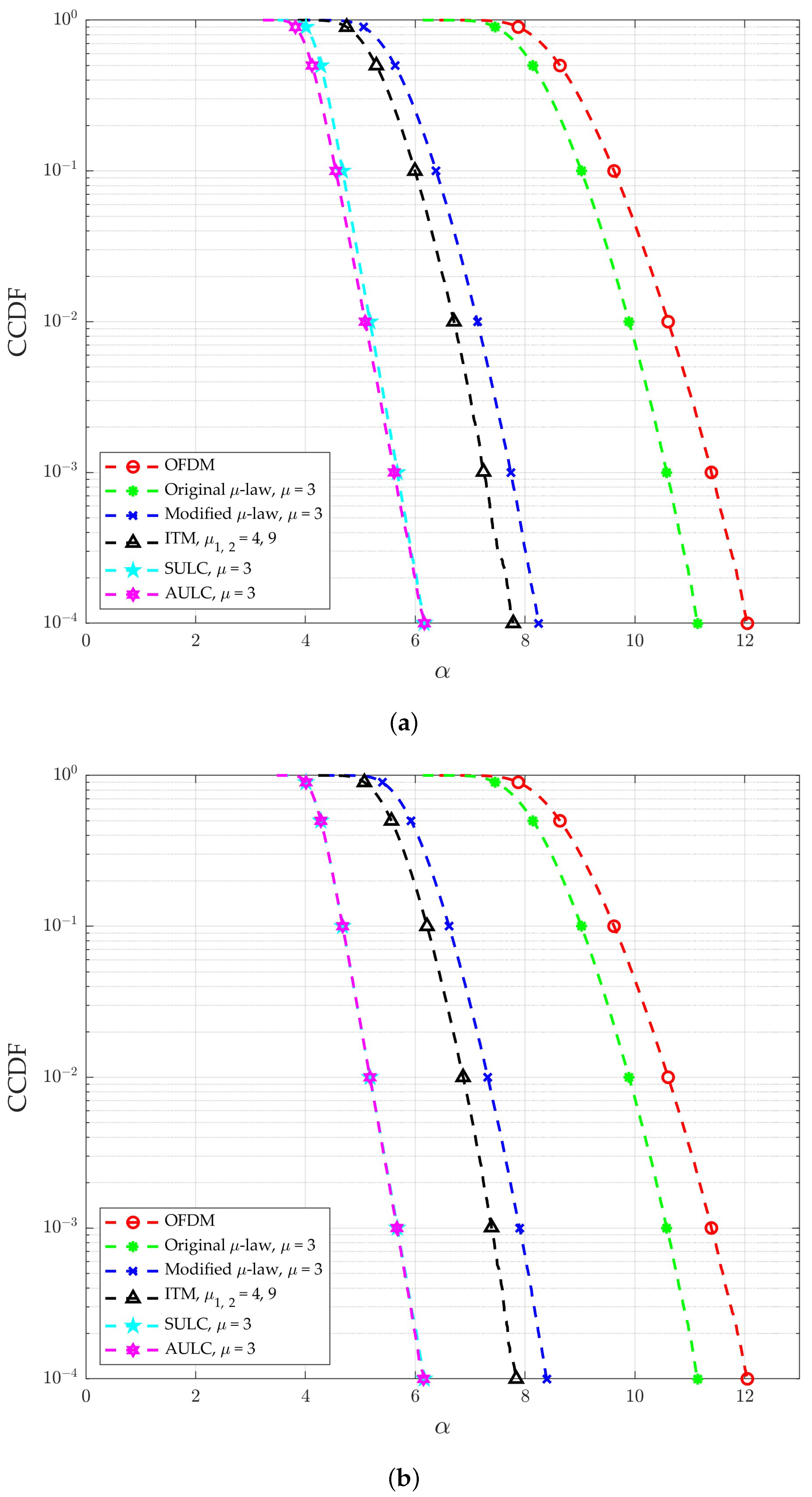
5. Simulation Results and Complexity Analysis

5.1. Experimental Scenarios and Results Discussion

In this section, we will verify some inferences and discuss the simulation results, involving the impact of varying the μ parameter on the performance, and evaluate the performance of the proposed methods compared with three schemes, including the original μ -law [31], modified μ -law [32], and ITM [33]. In addition, without loss of generality, we adopt the channel with AWGN that conforms to i.i.d.
To provide a clear explanation of the simulated scenarios in this article, we have listed the required parameters for all experiments in Table 1, and these parameters are utilized for complexity operation and its numerical analysis simultaneously. It is worth mentioning that without losing power fairness and generality, the focus of this paper is to discuss the comparison of PAPR reduction algorithms, and the amplifier’s signal will be beyond the discussed scope. Therefore, we neglect the influences of the average signal in the amplifier coming from μ -law companding. Of course, regardless of whether the power is normalized, it will not affect PAPR. Moreover, to alleviate the average signal power influence issues of μ -law companding, we have normalized the power of 256-QAM and 512-QAM in our experiments.
As aforementioned, in Figure 4, see from the curve for different μ parameter values that the more considerable x [ n ] value will obtain a more compressed amount, and vice versa, so the peak value is prone to being decreased and the lower value is prone to being enlarged, improving the PAPR. Moreover, to comprehend the influence of the μ parameter on PAPR and BER in the original μ -law method, we show the experiment results of μ vs. PAPR and μ vs. BER in Figure 5a,b for the original μ -law with QAM = 256, N = 512, respectively. Among them, to fare with the advanced B5G wireless communication protocol, according to [39,40], we know that under QAM order 256, the channel needs to have an SNR of 30 dB to meet the requirements of the receiving end. Therefore, this specification is incorporated into the BER curve simulation for μ parameters without loss of generality. In Figure 5a, it seems to merit that μ increases and PAPR is reduced. That has paid the BER cost, since all tone components are through nonlinear companding transform simultaneously. As expected, as shown in Figure 5b, when the value of μ increases, that makes the BER higher. Of course, this is not what we expected it to be. Even more discouraging is that the above two curves can only show individual trends and almost cannot obtain an optimal μ value of a balance point that is effective enough to be applied. Therefore, we are dedicated to finding a μ value that trades off PAPR and BER performance.
Therefore, the SULC scheme adopts a useful component-wise mechanic to alleviate the conflict between PAPR and BER in the original μ -law method. In other words, we perform companding partly, not all of them unconditionally. Thus, compared to the original μ -law, this proposed method can achieve a better balance between PAPR and BER. Similarly, Figure 5a,b and Figure 6a,b show the relationship of the μ parameter on PAPR and BER, respectively, including the SULC and the proposed AULC schemes. It is worth mentioning that the SULC results significantly prompt performance in PAPR due to all-around tone-companding decisions. Also, in either the SULC or proposed AULC schemes, the optimal μ numbers of PAPR and BER are at 4 and 2, respectively. Therefore, we can infer that the proposed method’s upper and lower bound of the μ value is between 4 and 2.
To echo the above inference, we compared the PAPR and BER between the SULC, AULC, and the original μ -law methods, where μ is 2, 3, and 4, as shown in Figure 7a,b. In light of this figure, it can be found that when the μ value is 4, PAPR has the best performance, but its BER performance is the worst. When the μ value is 2, although its BER performance is the best, the improvement in PAPR performance is the smallest. It can be seen that both μ are 2 and 4 are insufficiently balanced. Correspondingly, although the PAPR and BER performance does not reach top-notch when μ is 3, the BER remains good compared with the original μ -law, and PAPR has been dramatically improved.
To determine the μ value more streamlined and efficiently, we define the ratio between Δ B E R and Δ P A P R as parameter η , which is expressed as
η = Δ B E R Δ P A P R ,
where Δ B E R is the distance from 10 0 to the BER curve, and Δ P A P R is the distance between the PAPR curve and the origin, due to the lower BER indicating a greater Δ B E R and better PAPR performance indicating a lower Δ P A P R . Therefore, we infer that maximizing η will lead to the best choice of μ value. Furtherly, utilizing Equation (25), we redraw Figure 6 as Figure 8, which shows the μ vs. η curve for the SULC scheme and the proposed AULC scheme. Also, Figure 8 reveals that the most prominent point of η is at μ = 3. Hence, we verify again that μ = 3 is the best choice in our methods. Furthermore, from the parameter η , we observe the sensitivity of the μ value to the relative impact of the BER and PAPR for the SULC and proposed AULC. In other words, the PAPR variation is very small compared to BER in the proposed AULC, which is more sensitive to the μ value.
To verify the PAPR and BER performance of our proposed methods, the following simulation compares the SULC and proposed AULC schemes to other adopted companding technique’s PAPR reduction methods, such as original μ -law [31], modified μ -law [32], and ITM [33]. Figure 9a,b and Figure 10a,b show their PAPR and BER performance for 256-QAM and N of 512 and 1024, respectively, while Figure 11a,b and Figure 12a,b show their PAPR and BER performance in the case of 512-QAM and N of 512 and 1024, respectively.
Figure 9a,b describe the PAPR performance of each method, among which OFDM has not been improved in any way, and of course, it performs the worst. For instance, compared with OFDM when CCDF is 10 4 in Figure 9a, the original μ -law only reduces 0.91 dB when μ is 3; the effect is relatively poor. While the PAPR of SULC is 6.16 dB when μ is 3; compared with OFDM, the original μ -law, and the modified μ -law, and ITM improved by 5.89 dB, 4.98 dB, 2.08 dB, and 1.62 dB, respectively. As for the proposed AULC, the PAPR is almost the same as the SULC. Therefore, it can be verified that the proposed AULC maintains good performance while reducing complexity.
As shown in Figure 9b, as the number of subcarriers, N increases to 1024, the PAPR performance of the modified μ -law and ITM has a slightly worsening trend compared to Figure 9a. Comparatively, the proposed schemes almost maintain the same PAPR performance compared to N is 512. Moreover, the SULC scheme and the proposed AULC scheme still outperform the original OFDM performance by about 5.89 dB and 5.9 dB.
In terms of BER performance, as shown in Figure 10a, we can find that the performance of the modified μ -law and ITM are the poorest; as for others’ BER performances, such as OFDM, the original μ -law and our proposed methods in this article are almost overlapping, which is 1.43 × 10 4 at SNR is 30 dB. It is worth mentioning that compared with the original μ -law, the modified μ -law, and ITM, the BER performance of the proposed methods is improved by approximately 6%, 75%, and 84%, respectively. When the number of subcarriers, N, increases to 1024, as shown in Figure 10b, they maintain the same relationship characteristics. Therefore, from Figure 9 and Figure 10, we know that our proposed methods are suitable for future communication systems with high subcarriers compared to others from both PAPR and BER performance perspectives.
We further observe the impact of different order QAMs on the PAPR and BER performance for various methods, as shown in Figure 11 and Figure 12, respectively.
In Figure 11, we increase the QAM order to 512 from 256 compared to Figure 9. The PAPR performance of our proposed schemes is still the best among all methods. In terms of the BER, in Figure 12, the order of QAM is increased to 512 from 256 compared to Figure 10, which can verify that the BER performance of the proposed schemes will not be affected.
To pursue the specifications of future B5G wireless communication systems, increasing the order of modulation and raising the number of subcarriers is an inevitable trend since higher modulation orders result in greater data throughput, and an increased number of subcarriers leads to a faster transmission rate. From Figure 9, Figure 10, Figure 11 and Figure 12, whether it is PAPR or BER, we can observe that increasing the order of modulation and the number of subcarriers has almost no impact on our proposed method. Of course, this is bullish news. For more clarity, the detailed PAPR data are enumerated in Table 2. Consequently, it is confirmed that the proposed methods remain applicable in B5G systems with elevated requirements for modulation order and the number of subcarriers.
Summarizing the results above, our proposed schemes can effectively improve the PAPR and maintain the BER before improvement by selecting an appropriate μ value. Also, without sacrificing PAPR and BER performance, our proposed schemes can still be held under more subcarriers and a higher modulation order environment. Thus, they can keep up with B5G.

5.2. Computational Complexity Analysis and Performance Discussion

5.2.1. Complexity Expression Analysis

In this subsection, we evaluate the computational complexity of other schemes and the proposed schemes regarding the number of complex multiplications and additions (CMAs) required [14]. We enumerate the needed parameters in Table 1 for a more explicit description, such as N is the number of subcarriers, etc. In addition, since the μ -law scheme uses logarithm operations, the complexity of logarithm operations can be expressed as the order of O log ( · ) in this paper. Next, we derive and describe the complex multiplications and additions (CMAs) expressions required for each scheme in the following.
Regarding the original μ -law scheme and the modified μ -law scheme, the OFDM signal is compressed or expanded through the corresponding companding equation. Therefore, the former requires a total of multiplications and additions of approximately ( N 2 + 4 N ) and ( N 2 + 1 ) CMAs, respectively, as well as ( N + 1 ) logarithm operations, and the latter involves a sum of ( N 2 + 6 N ) multiplications, ( N 2 + 2 N 1 ) additions, and ( N + 1 ) logarithm operations.
As for the ITM, the scheme is segmentally companding using a threshold value and two different μ values. An offset is introduced in the second section to achieve a smooth transition from μ 1 to μ 2 . Finally, it is multiplied by a normalization factor K, which is approximately the square root of the ratio of the two signal powers. Therefore, approximately ( N 2 + 7 N ) multiplications, ( N 2 + 7 N 2 ) additions, and ( N + 1 ) logarithm operations are required.
For the SULC scheme, each tone component is subjected to companding one by one, sequentially, and the elements with better PAPR are selected and retained until each tone component is completed. Therefore, it needs ( 3 N 2 + 9 N + 3 ) multiplications, ( 3 N 2 + N 2 ) additions, and ( N + 1 ) logarithm operations. As for the proposed AULC scheme, which divides the input signal of length N into two groups. The first group has β r o u g h tone components, which execute parallel companding the same as the original μ -law, and the remaining ( N β r o u g h ) tone components only partially implement the SULC scheme. In total, the process requires roughly 1.32 N 2 + 3.6 N + 3 + β r o u g h ( 0.32 β r o u g h 0.64 N + 0.4 ) multiplications, 1.32 N 2 0.2 N 2 + β r o u g h ( 0.32 β r o u g h 0.64 N + 0.2 ) additions, and ( 0.4 N + 1 + 0.6 β r o u g h ) logarithm operations. For convenience of reference, we provide the analytical expression of the total number of CMAs required for the above schemes in Table 3.

5.2.2. Computational Complexity Discuss and Numerical Analysis

In this subsection, we compare the numerical analysis of the computational complexity among the above-mentioned schemes. Substitute the parameter values of Table 1 into the expressions of Table 3 to obtain the CMAs numerical values of each scheme when subcarrier N is equal to 512 and 1024, as listed in Table 4, and its bar chart is shown in Figure 13.
To discuss each scheme in more detail, we first consider the case of N = 512 in Figure 9a and Figure 10a and Table 4 regarding both PAPR and complexity. At first glance, the original μ -law scheme has 526,337 CAMs, which is the lowest complexity among all compared schemes and seems the best choice. However, this scheme exhibits awful PAPR performance to maintain good BER performance. In contrast, although the complexity of the SULC is inferior to the original μ -law method, its PAPR performance is much better than the original μ -law scheme while maintaining good BER performance. On the other hand, the proposed AULC further improves complexity performance by 64.4% compared to SULC while exhibiting almost identical PAPR and BER performance.
Similarly, we again consider the case of N = 1024 in Figure 9b and Figure 10b and Table 4 regarding both PAPR and complexity. Due to the increase in the number of subcarriers, the complexity of various schemes has shown a rising trend. Among them, the modified μ -law and ITM schemes exhibit slightly degraded PAPR performance. Fortunately, increasing the number of subcarriers has almost no impact on our proposed method. In other words, they are not the optimal solution in a high subcarrier environment.
In summary, the SULC and the proposed AULC exhibit the best PAPR performance among all the schemes while maintaining a good BER. Compared to the original μ -law scheme, the modified μ -law scheme, and the ITM scheme, the proposed AULC scheme demonstrates superior performance in terms of PAPR with improvements of 45%, 26%, and 21%, respectively. Regarding BER performance, it outperforms the mentioned schemes by 6%, 75%, and 84%, respectively. In addition, in terms of complexity, compared to the original μ -law scheme, modified μ -law scheme, and ITM scheme, the proposed AULC method only requires a moderate increase in complexity of approximately 6.3%, 5.9%, and 5.4%, respectively. In other words, in light of the tradeoff between complexity, PAPR, and BER, the proposed AULC has extremely obvious advantages at PAPR and BER. Also, the complexity is very close to that of other companding methods.

6. Conclusions

The peak-to-average power ratio (PAPR) issue within multiple-carrier technology is still troublesome for advanced wireless systems. Although many solutions have been proposed, each method has different pros and cons. Of course, no single approach will handle such tricky needs comprehensively. Among them, nonlinear companding transform (NCT) is one of the simple and popular technologies, especially the μ -law rule. In this paper, we utilize the balance between BER and PAPR, adopt the Monte Carlo method, and define the ratio of improved BER to improved PAPR, η , to estimate the appropriate μ value more accurately. Thus, the SULC scheme can enhance the PAPR and not damage the BER. Moreover, the AULC scheme is proposed to improve complexity more efficiently. It sorts the transmission signals according to their amplitudes. Then, it estimates the rough companding tone amount (around 54% of the subcarriers) to separate the tones of the OFDM signal into two groups. The hybrid combination of the original μ -law’s parallel companding behavior and the partial sequential μ -law’s component-wise companding can reduce complexity compared to the SULC method. Simulation results and numerical analysis demonstrate that our proposed AULC scheme outperforms previous companding techniques regarding both PAPR and BER.

Author Contributions

Conceptualization, Y.-P.T., Z.-T.Z. and Y.-F.H.; methodology, Y.-P.T.; software, Z.-T.Z.; validation, Y.-P.T.; formal analysis, Y.-P.T.; investigation, Y.-P.T. and Y.-F.H.; resources, Y.-P.T.; data curation, Y.-P.T. and Z.-T.Z.; writing—original draft preparation, Y.-P.T. and Z.-T.Z.; writing—review and editing, Y.-P.T. and Y.-F.H.; visualization, Y.-P.T. and Z.-T.Z.; supervision, Y.-P.T.; project administration, Y.-P.T.; funding acquisition, Y.-F.H. and Y.-P.T. All authors have read and agreed to the published version of the manuscript.

Funding

This research was funded by the National Science and Technology Council (NSTC), Taiwan, with grant number NSTC 112-2221-E-324-010.

Data Availability Statement

All data underlying the results are available as part of the article, and no additional source data are required.

Conflicts of Interest

The authors declare no conflicts of interest.

Abbreviations

The following abbreviations are used in this manuscript:
5Gfifth-generation
A/Danalog-to-digital
AULCalternating μ -law companding
AWGNadditive white Gaussian noise
B5Gbeyond fifth-generation
BERbit error rate
CCDFcomplementary cumulative distribution function
CMAscomplex multiplications and additions
D/Adigital-to-analog
DCTdiscrete cosine transform
FFTfast Fourier transform
HPAhigh-power amplifier
IFFTinverse fast Fourier transform
i.i.d.independent and identically distributed
IoTInternet of Things
ISIinter-symbol interference
ITMimproved two- μ s
NCT        nonlinear companding transform
OFDMorthogonal frequency division multiplexing
PAPRpeak-to-average power ratio
PRTpeak reduction tones
PTSpartial transmit sequence
QAMquadrature amplitude modulation
SEspectral efficiency
SLM         selective mapping
SULCsequential μ -law companding
TItone injection
TRtone reservation

References

  1. Hassebo, A.; Tealab, M. Global Models of Smart Cities and Potential IoT Applications: A Review. IoT 2023, 4, 366–411. [Google Scholar] [CrossRef]
  2. Ghashim, I.A.; Arshad, M. Internet of Things (IoT)-Based Teaching and Learning: Modern Trends and Open Challenges. Sustainability 2023, 15, 15656. [Google Scholar] [CrossRef]
  3. Gubbi, J.; Buyya, R.; Marusic, S.; Palaniswami, M. Internet of Things (IoT): A vision, architectural elements, and future directions. Future Gener. Comput. Syst. 2013, 29, 1645–1660. [Google Scholar] [CrossRef]
  4. Wang, D.; Chen, D.; Song, B.; Guizani, N.; Yu, X.; Du, X. From IoT to 5G I-IoT: The next generation IoT-based intelligent algorithms and 5G technologies. IEEE Commun. Mag. 2018, 56, 114–120. [Google Scholar] [CrossRef]
  5. Shafique, K.; Khawaja, B.A.; Sabir, F.; Qazi, S.; Mustaqim, M. Internet of things (IoT) for next-generation smart systems: A review of current challenges, future trends and prospects for emerging 5G-IoT scenarios. Ieee Access 2020, 8, 23022–23040. [Google Scholar] [CrossRef]
  6. Cho, Y.S.; Kim, J.; Yang, W.Y.; Kang, C.G. MIMO-OFDM Wireless Communications with MATLAB; John Wiley & Sons: Hoboken, NJ, USA, 2010. [Google Scholar] [CrossRef]
  7. Nee, R.V.; Prasad, R. OFDM for Wireless Multimedia Communications; Artech House, Inc.: Boston, MA, USA, 2000. [Google Scholar]
  8. Wen, M.; Li, Q.; Cheng, X. Index Modulation for OFDM Communications Systems; Springer: Berlin/Heidelberg, Germany, 2021. [Google Scholar] [CrossRef]
  9. Harkat, H.; Monteiro, P.; Gameiro, A.; Guiomar, F.; Farhana Thariq Ahmed, H. A survey on MIMO-OFDM systems: Review of recent trends. Signals 2022, 3, 359–395. [Google Scholar] [CrossRef]
  10. Rawat, A.; Kaushik, R.; Tiwari, A. An overview of MIMO OFDM system for wireless communication. Int. J. Tech. Res. Sci. 2021, 6, 1–4. [Google Scholar] [CrossRef]
  11. Aarab, M.N.; Chakkor, O. MIMO-OFDM for Wireless Systems: An Overview. In Advanced Intelligent Systems for Sustainable Development (AI2SD’2019); Ezziyyani, M., Ed.; Lecture Notes in Networks and Systems; Springer: Cham, Switzerland, 2020; Volume 92. [Google Scholar] [CrossRef]
  12. Jiang, T.; Wu, Y. An overview: Peak-to-average power ratio reduction techniques for OFDM signals. IEEE Trans. Broadcast. 2008, 54, 257–268. [Google Scholar] [CrossRef]
  13. Lim, D.W.; Heo, S.J.; No, J.S. An overview of peak-to-average power ratio reduction schemes for OFDM signals. J. Commun. Netw. 2009, 11, 229–239. [Google Scholar] [CrossRef]
  14. Tu, Y.P.; Chang, C.C. A Novel Low Complexity Two-Stage Tone Reservation Scheme for PAPR Reduction in OFDM Systems. Sensors 2023, 23, 950. [Google Scholar] [CrossRef]
  15. Mounir, M.; Youssef, M.I.; Tarrad, I.F. On the effectiveness of deliberate clipping PAPR reduction technique in OFDM systems. In Proceedings of the 2017 Japan-Africa Conference on Electronics, Communications and Computers (JAC-ECC), Alexandria, Egypt, 18–20 December 2017; pp. 21–24. [Google Scholar] [CrossRef]
  16. Tang, B.; Qin, K.; Chen, C.; Cao, Y. A novel clipping-based method to reduce peak-to-average power ratio of ofdm signals. Information 2020, 11, 113. [Google Scholar] [CrossRef]
  17. Omata, S.; Shirai, M.; Sugiyama, T.; Urata, I.; Yamashita, F. PAPR and BER Performances of Direct Spectrum Division Transmission Applied by Clipping and Filtering in ACI Environment. In Proceedings of the 2019 IEEE 90th Vehicular Technology Conference (VTC2019-Fall), Honolulu, HI, USA, 22–25 September 2019; pp. 1–5. [Google Scholar] [CrossRef]
  18. Muller, S.H.; Huber, J.B. A novel peak power reduction scheme for OFDM. In Proceedings of the 8th International Symposium on Personal, Indoor and Mobile Radio Communications-PIMRC’97, Helsinki, Finland, 1–4 September 1997; Volume 3, pp. 1090–1094. [Google Scholar] [CrossRef]
  19. Gupta, P.; Thethi, H.P.; Tomer, A. An efficient and improved PTS algorithm for PAPR reduction in OFDM system. Int. J. Electron. 2022, 109, 1252–1277. [Google Scholar] [CrossRef]
  20. Peng, Y.; Li, M. A novel PTS scheme for PAPR reduction of filtered-OFDM signals without side information. Teh. Vjesn. 2020, 27, 1305–1310. [Google Scholar]
  21. Yuan, Y.; Wei, S.; Luo, X.; Xu, Z.; Guan, X. Adaptive PTS scheme based on fuzzy neural network for PAPR reduction in OFDM system. Digit. Signal Process. 2022, 126, 103492. [Google Scholar] [CrossRef]
  22. Bami, R.; Fischer, R.; Hber, J. Reducing the peak-to-average power ratio of multicarrier modulation by selective mapping. Electron. Lett. 1996, 32, 2056–2057. [Google Scholar] [CrossRef]
  23. Wei, S.; Li, H.; Han, G.; Zhang, W.; Luo, X. PAPR reduction of SLM-OFDM using Helmert sequence without side information. In Proceedings of the 2019 14th IEEE Conference on Industrial Electronics and Applications (ICIEA), Xi’an, China, 19–21 June 2019; pp. 533–536. [Google Scholar] [CrossRef]
  24. Prasad, S.; Jayabalan, R. PAPR reduction in OFDM systems using modified SLM with different phase sequences. Wirel. Pers. Commun. 2020, 110, 913–929. [Google Scholar] [CrossRef]
  25. Gupta, P.; Thethi, H.P. Performance Investigations and PAPR Reduction Analysis Using Very Efficient and Optimized Amended SLM Algorithm for Wireless Communication OFDM System. Wirel. Pers. Commun. 2020, 115, 103–128. [Google Scholar] [CrossRef]
  26. Wang, W.; Hu, M.; Yi, J.; Zhang, H.; Li, Z. Improved cross-entropy-based tone injection scheme with structured constellation extension design for PAPR reduction of OFDM signals. IEEE Trans. Veh. Technol. 2017, 67, 3284–3294. [Google Scholar] [CrossRef]
  27. Hu, M.; Wang, W.; Cheng, W.; Zhang, H. Initial probability adaptation enhanced cross-entropy-based tone injection scheme for PAPR reduction in OFDM systems. IEEE Trans. Veh. Technol. 2021, 70, 6674–6683. [Google Scholar] [CrossRef]
  28. Park, S.E.; Yun, S.R.; Kim, J.Y.; Park, D.S.; Joo, P. Tone reservation method for PAPR reduction scheme. Proj. IEEE 2003. Available online: https://www.ieee802.org/16/tge/contrib/C80216e-03_60.pdf (accessed on 5 February 2024).
  29. Wang, B.; Si, Q.; Jin, M. A novel tone reservation scheme based on deep learning for PAPR reduction in OFDM systems. IEEE Commun. Lett. 2020, 24, 1271–1274. [Google Scholar] [CrossRef]
  30. Upadhyaya, Y.K.; Kushwaha, A.K. Minimize Power Ratio (PR) in OFDM Using Tone Reservation Method. In Soft Computing: Theories and Applications: Proceedings of the SoCTA 2019; Springer: Berlin/Heidelberg, Germany, 2019; pp. 115–124. [Google Scholar] [CrossRef]
  31. Proakis, J.G.; Salehi, M. Communication Systems Engineering, 2nd ed.; Prentice-Hall: Upper Saddle River, NJ, USA, 2001. [Google Scholar]
  32. Wang, X.; Tjhung, T.T.; Ng, C.S. Reduction of peak-to-average power ratio of OFDM system using a companding technique. IEEE Trans. Broadcast. 1999, 45, 303–307. [Google Scholar] [CrossRef]
  33. Ali, N.; Almahainy, R.; Al-Shabili, A.; Almoosa, N.; Abd-Alhameed, R. Analysis of improved μ-law companding technique for OFDM systems. IEEE Trans. Consum. Electron. 2017, 63, 126–134. [Google Scholar] [CrossRef]
  34. Yenamandra, V.; Lei, F.; Al-Araji, S.; Ali, N.; Ismail, M. Adaptive slope and threshold companding technique for PAPR reduction in OFDM systems. In Proceedings of the 2012 19th IEEE International Conference on Electronics, Circuits, and Systems (ICECS 2012), Seville, Spain, 9–12 December 2012; pp. 312–315. [Google Scholar] [CrossRef]
  35. Pratt, T.G.; Jones, N.; Smee, L.; Torrey, M. OFDM link performance with companding for PAPR reduction in the presence of non-linear amplification. IEEE Trans. Broadcast. 2006, 52, 261–267. [Google Scholar] [CrossRef]
  36. Malini, M.A.H.; Selvi, M. Improved Companding Technique with Different Modulation Schemes for Better Papr in of DM Systems; The Mattingley Publishing Co., Inc.: 2020. Available online: https://www.academia.edu/106742291/Improved_Companding_Technique_with_Different_Modulation_Schemes_for_Better_Papr_in_of_DM_Systems (accessed on 5 February 2024).
  37. Shri Ramtej, K.; Anuradha, S. Modified μ-Law Companding Transform for PAPR Reduction in SC-FDMA Systems. In Optical and Wireless Technologies: Proceedings of the OWT 2018; Springer: Berlin/Heidelberg, Germany, 2018; pp. 377–386. [Google Scholar] [CrossRef]
  38. Ramavath, S.; Kshetrimayum, R.S. Analytical calculations of CCDF for some common PAPR reduction techniques in OFDM systems. In Proceedings of the 2012 International Conference on Communications, Devices and Intelligent Systems (CODIS), Kolkata, India, 28–29 December 2012; pp. 393–396. [Google Scholar]
  39. Urban, D.J. The importance of wi-fi 6 technology for delivery of gbps internet service. SCTE ISBE Cable-Tec. Expo. 2019. Available online: https://www.nctatechnicalpapers.com/Paper/2019/2019-the-importance-of-wifi-6-technology-for-delivery-of-gbps-internet-service (accessed on 5 February 2024).
  40. Minimum 802.11 SNR Sensitivity. Available online: https://interline.pl/Information-and-Tips/Minimum-802.11-SNR-Sensitivity (accessed on 31 July 2022).
Figure 1. The basic architecture block diagram of OFDM systems.
Electronics 13 00694 g001
Figure 2. The block diagram of μ -law companding used in OFDM systems.
Electronics 13 00694 g002
Figure 3. Sign function with complex input.
Electronics 13 00694 g003
Figure 4. Discuss the relationship between | x [ n ] | and l o g ( 1 + μ | x [ n ] | ) l o g ( 1 + μ ) with different μ .
Electronics 13 00694 g004
Figure 5. Original μ -law with QAM = 256, N = 512 (a) μ vs. PAPR (b) μ vs. BER at SNR = 30 dB.
Electronics 13 00694 g005
Figure 6. SULC and AULC with QAM = 256, N = 512 (a) μ vs. PAPR (b) μ vs. BER at SNR = 30 dB.
Electronics 13 00694 g006
Figure 7. Compare (a) PAPR and (b) BER for SULC ( μ = 2, 3, 4), AULC ( μ = 2, 3, 4), original μ -law ( μ = 2, 3, 4), and OFDM with QAM = 256, N = 512.
Electronics 13 00694 g007
Figure 8. μ vs. η for SULC and AULC with QAM = 256, N = 512, and SNR = 30 dB.
Electronics 13 00694 g008
Figure 9. PAPR performance of different schemes, at QAM = 256 (a) N = 512 and (b) N = 1024.
Electronics 13 00694 g009
Figure 10. BER performance of different schemes, at QAM = 256 (a) N = 512 and (b) N = 1024.
Electronics 13 00694 g010
Figure 11. PAPR performance of different schemes, at QAM = 512 (a) N = 512 and (b) N = 1024.
Electronics 13 00694 g011
Figure 12. BER performance of different schemes, at QAM = 512 (a) N = 512 and (b) N = 1024.
Electronics 13 00694 g012
Figure 13. The bar chart of computational complexity for different schemes with N = 512 and N = 1024.
Electronics 13 00694 g013
Table 1. Simulation scenario and related parameters.
Parameter NameValue
The number of experiments for Monte Carlo 10 6
The order of QAM256, 512
N, number of subcarriers512, 1024
β r o u g h , the quantity of the first group in the AULC method 0.54 N
Table 2. Enumerate the PAPR numerical of SULC and proposed AULC at QAM = 256 and 512, N = 512 and 1024 when CCDF is 10 4 .
Scheme Name256-QAM512-QAM
N = 512 N = 1024 N = 512 N = 1024
SULC6.16 dB6.16 dB6.14 dB6.14 dB
AULC6.14 dB6.15 dB6.12 dB6.14 dB
Table 3. Analytical expression of the computational complexity of the above scheme.
Scheme NameNumber of Complex MultiplicationsNumber of Complex
Additions
Number of O log ( · )
Original μ -law [31] ( N 2 + 4 N ) ( N 2 + 1 ) ( N + 1 )
Modified μ -law [32] ( N 2 + 6 N ) ( N 2 + 2 N 1 ) ( N + 1 )
ITM [33] ( N 2 + 7 N ) ( N 2 + 7 N 2 ) ( N + 1 )
SULC ( 3 N 2 + 9 N + 3 ) ( 3 N 2 + N 2 ) ( N + 1 )
AULC 1.32 N 2 + 3.6 N + 3
+ β r o u g h ( 0.32 β r o u g h 0.64 N + 0.4 )
1.32 N 2 0.2 N 2
+ β r o u g h ( 0.32 β r o u g h 0.64 N + 0.2 )
( 0.4 N + 1
+ 0.6 β r o u g h )
Table 4. The numerical comparison of complexity for different schemes with N = 512 and 1024.
Scheme Name N = 512 N = 1024
CMAs O log ( · ) CMAs O log ( · )
Original μ -law [31]526,3375132,101,2491025
Modified μ -law [32]528,3835132,105,3431025
ITM [33]531,4545132,111,4861025
SULC1,577,9855136,301,6971025
AULC561,6963722,242,967742
Disclaimer/Publisher’s Note: The statements, opinions and data contained in all publications are solely those of the individual author(s) and contributor(s) and not of MDPI and/or the editor(s). MDPI and/or the editor(s) disclaim responsibility for any injury to people or property resulting from any ideas, methods, instructions or products referred to in the content.

