Article

Active Power Allocation Method of Doubly Fed Induction Generators Based on Rotor Speed

College of Electrical Engineering, Xinjiang University, Urumqi 830017, China
*
Author to whom correspondence should be addressed.
Electronics 2024, 13(2), 279; https://doi.org/10.3390/electronics13020279
Submission received: 11 December 2023 / Revised: 4 January 2024 / Accepted: 4 January 2024 / Published: 8 January 2024

Abstract

:
The integration of wind power into a grid on a large scale results in a reduction of the system’s inertia level, causing an impact on the stability of the system frequency. Doubly fed induction generators (DFIG) can optimize active output but lack inertia support under maximum power point tracking control. To make the wind turbine improve the inertia support ability of the system based on virtual inertia control, a method for active power allocation based on the rotor speed of DFIG is proposed. Firstly, the minimum system inertia requirement based on the frequency change rate of the system is established. Active power allocation assumes that the wind farm inertia meets the minimum system inertia requirement. Secondly, the objective is to enhance the inertia support capability and overall active power output of the wind farm, considering the constraint of the minimum system inertia requirement. Based on the rotor speed to establish the inertia allocation weight factor, the weight of the power command is assigned to a single machine to achieve the wind farm active power allocation. Finally, it is verified that the system’s equivalent inertia meets the minimum inertia requirement of the system. Simulations show that the proposed allocation method can adequately elevate the inertia support capability of DFIGs to the system and the rotor kinetic energy utilization.

1. Introduction

With the depletion of fossil energy sources and severe environmental problems, countries worldwide are pushing for clean energy generation, particularly wind and solar power plants [1]. Countries around the world have made different efforts to save energy and reduce emissions [2], and all parties are encouraged by the 2015 Paris Agreement to enhance the global response to the threat of climate change. China has proposed a dual-carbon target for 2020, striving to achieve a carbon peak by 2030 and carbon neutrality by 2060 [3]. The global wind energy industry will maintain a rapid development trend, and the globally installed wind power capacity will keep growing. According to the Global Wind Energy Report published by the Global Wind Energy Council (GWEC) in 2023 [4], the proportion of the newly installed wind power capacity in the Asia–Pacific region to the new globally installed capacity in 2022 reached 48%. In the future, there will be a significant increase in the share of renewable energy in the power system.
Grid connection of wind turbine generators (WTGs) through converters leads to the decoupling of the rotor speed from the system frequency, which does not supply inertia support for the system. At the same time, the proportion of synchronous generators in the system is reduced, resulting in a lower overall inertia level of the system [5,6]. The low inertia systems are poorly stabilized, and power perturbations will result in a high rate of change of frequency (RoCoF) and a higher frequency deviation value [7]. Although WTGs based on maximum power point tracking (MPPT) satisfy the maximum active output of the turbine, WTGs without additional control are unable to provide inertia support to the system [8,9]. References [10,11] propose to provide inertia support through additional energy storage devices, but the economic cost is too high. The doubly fed induction generator (DFIG) has emerged as a preferred solution for large-scale wind farms due to its adjustable speed, low-risk profile, and ease of maintenance [12]. The implementation of virtual inertia control (VIC) in DFIG control has demonstrated the ability to harness the rotor kinetic energy of WTGs, thereby enhancing their capacity to provide inertia support to the system [13,14]. References [15,16] evaluated the equivalent inertia of DFIG and provided inertia support to the system based on VIC, which improved the system frequency response. It somewhat improves the inertial support capacity of DFIG for the system. However, it blurs the inertial support capacity of a single wind turbine (WT). Conventional VIC does not consider the WT’s inherent capability for inertial response and inertial distribution. Suppose virtual inertia is evenly allocated across all turbines. In that case, each unit will have an identical inertial response, causing specific units to release excessive rotor kinetic energy and shut down prematurely, while other units will not fully utilize their inertial response [17].
Active power allocation can fully use the inertia regulation capability of a single WT to satisfy the power balance between systems and enable stable system operation. Though the study of inertia control at the WT level is relatively mature, most current studies of the problem of active power allocation between wind farm units simply consider the wind speed uniform and do not give the differences in wind speed between units. Wind speed affects rotor speed, and it is difficult to give full play to the inertia support capability of wind turbines if the effect of speed differences is not considered. Therefore, the active power output of a single WT is coordinated from the wind farm level [18]. In Reference [19], the frequency modulation (FM) weighting factor of a WT is defined based on the wind speed to characterize the ability of a single WT to participate in the system FM before active power allocation. However, there are limitations in considering only wind speed, which does not consider the effect of real-time rotor speed and does not consider the allocation in terms of providing inertia to support the power. The proposed method in Reference [20] presents a real-time active power control strategy for wind farms based on the ranking of WTs’ control capabilities. However, it fails to consider the system inertia requirements and is influenced by the accuracy of wind power prediction. A site-level collaborative allocation strategy is proposed in Reference [21], which utilizes the empirical pattern decomposition of wind speeds and a BP neural network training algorithm to consider the variability of WTGs’ inertial response capabilities. However, the allocation process does not explicitly give the quantitative relationship between the two weights and does not simulate the results of the stand-alone allocation.
Most of the current research focuses on FM capability classification and FM power allocation, and there is a dearth of research on inertia support and the distribution of power to provide inertia support. Consequently, considering the shortcomings of the current research area, this aspect of the study was supplemented. In terms of the stable operation of low-inertia wind power systems, the inertial support capacity of the WT to the system is improved in the following ways. In this paper, a rotor speed-based active power allocation method for DFIG is proposed, aiming to improve the inertia support capability of the system. To study the inertia support capability of DFIG to the system, VIC is introduced to analyze the inertia support capability of DFIG under different wind conditions. Taking the minimum inertia demand of the system as the constraint, with the objective of improving the inertia support capability and overall active power output of the wind farm, and taking the turbine speed as the influencing factor, the inertia allocation weighting factor is established. Taking the inertial support power as the total amount of allocation, power commands are allocated to individual machines according to their different weights to achieve active power allocation of the wind farm. Finally, the simulation verifies the effectiveness of the method.
The main contribution of this paper is to provide a new approach to inertia support that links power allocation and inertia support. The rational utilization of wind energy according to the operating differences of wind turbines flexibly utilizes the inertia regulation capability of a single wind turbine, while enhancing the stability of system operation.
This paper is structured as follows: Section 2 analyzes the inertial support capacity of the WT under different wind conditions. Section 3 proposes a rotor speed-based active power allocation method for DFIG. Section 4 verifies the validity of the proposed active power allocation method. Section 5 concludes.

2. Analysis of Wind Turbine Inertia Support Capacity

2.1. Subsection

A DFIG consists of a WT, a generator, a rotor-side converter, and a grid-side converter, where the WT is aerodynamically modeled:
P wind = 1 2 ρ A v 3 C p T wind = P wind ω λ = ω R v
where Pwind is the captured wind power, ρ is the air density in the current environment, A is the swept area of the WT, v is the wind speed, Cp is the wind capture coefficient, Twind is the aerodynamic torque, ω is the angular velocity of the impeller, and λ is the tip speed ratio.
The output mechanical power of the DFIG under MPPT control can be represented as:
P MPPT = P opt = k opt ω 3 k opt = 1 2 ρ A R λ opt 3 C popt
where kopt is the turbine-related constant, and R is the radius of the WT.
Under MPPT control, the WT active output can be maximized. However, because the rotor decouples from the system frequency, the wind turbine controlled by the MPPT alone cannot provide inertial support. Therefore, additional control must be introduced to fully use the turbine rotor’s kinetic energy to provide inertial support for the system. VIC is introduced in the WTGs’ generation control, and the control block diagram is shown in Figure 1. After the system is disturbed by imbalance, the rotor speed of the wind turbine controlled by virtual inertia will change, and the stored rotational kinetic energy can be expressed as:
E = 1 2 J ω 2
where J is the WT mechanical moment of inertia.
The WT can provide inertia-supported active power ΔPW as:
Δ P W = d E d t = J ω ω 0 d ω ω 0 d t = J ω ω 0 d f d t
where ω0 is the WT rotor speed rating, and f is the grid point frequency.
Before the WTGs provide inertia support to the system, the minimum inertia demand of the system on the WTGs needs to be evaluated to measure the anti-jamming ability of the system in the event of an expected failure. In the early stage of the system being perturbed, there is no generator governor or load frequency regulation effect, and the system frequency depends on the size of the system inertia. Currently, the RoCoF is at its maximum when the system is initially disturbed. Countries have set different limits on the RoCoF, ranging from 0.2 to 0.6 Hz/s, such as 0.2 Hz/s in the United Kingdom, 0.4 Hz/s in Ireland, and 0.6 Hz/s in Cyprus [22,23]. In this paper, the RoCoF is set to 0.5 Hz/s. After the active power imbalance caused by a fault in the system, Equation (5) can be obtained from the RoCoF constraints:
Δ f ˙ = Δ P f 2 H sys , min f 0 Δ f ˙ max
where Δ f ˙ is the RoCoF of the system, ΔPf is the amount of active power change due to disturbance, f0 is the initial frequency of the system, and Hsys,min is the minimum inertia demand of the system.
From Equation (5), the expression for the minimum inertia requirement of the system is:
H sys , min = Δ P f 2 Δ f ˙ max f 0
When the frequency variation is greater than the dead zone (generally, ±0.03~0.1 Hz), and the active power is greater than 20% of the rated power according to the current Chinese standard technical regulations, the wind farm should meet the conditions of Equation (7) to provide inertia support, and the wind farm active power variation ΔPt should satisfy Equation (8) [24].
Δ f × d f d t > 0
Δ P t = 2 H sys , min f 0 × d f d t × P t
where Δf is the frequency deviation, Pt is the active power of the wind farm.

2.2. Analysis of WT Inertia Support Capacity

For conventional synchronous generators, the inertia time constant can be used to quantify the magnitude of inertia by expressing the inertia time constant H of a single generator as:
H = E S N = J ω 0 2 2 S N
where SN is the rated capacity.
In the WT without additional control and only MPPT control, the WT output power reaches the maximum Pmax, but because the rotor is decoupled from the system frequency, the rotor speed cannot respond to the system frequency change and cannot provide inertia support. At the moment, the source of inertia in the system is all from the synchronous generator. At this time, the equivalent inertia Heq0 of the system can be expressed as:
H eq 0 = h = 1 l H G g S G g h = 1 l S G g
where HGg is the standalone inertia time constant of synchronous generator h, SGg is the rated capacity of synchronous machine h, and l is the total number of synchronous machines operating in the system.
After the additional VIC of the WT, the rotor kinetic energy is added to the reference power, and the output power of the WT is not greater than Pmax due to the withdrawal of MPPT control. At this time, the source of the system inertia needs to consider the traditional inertia of synchronous units and the virtual inertia of the WT, and the system equivalent inertia Heq1 can be expressed as follows:
H eq 1 = h = 1 l H G g S G g + E W h = 1 l S G g + S W
where EW is the energy of the WT to provide inertial support, and SW is the rated capacity of the WT.
The energy to which WT can provide inertial support depends on the rotor speed, which is related to the wind speed. The Jensen model is characterized by simple form and proper accuracy and is suitable for modeling the wake of WT in flat terrain [25]. According to the Jensen wake model, the wind speed of each WT in the wind farm is inconsistent due to the wake effect. The wind speed affects the rotational speed of the turbine, which, in turn, affects the magnitude of the inertia of each WT.
Before providing inertia support, the first step is to determine whether the wind farm has the inertia support capability to meet the system demand at the current wind speed, which can be discussed in the following two cases.
(1)
ΔPt > PWmax, where PWmax is the maximum power output of the wind farm at the current wind speed. Case 1 indicates that at this time, the wind farm cannot provide inertia-supporting power for the system and cannot satisfy the minimum inertia demand of the system, which requires energy storage to assist in providing active power.
(2)
ΔPtPWmax, case 2, indicates that the wind farm can meet the power of inertial support required by the system at this time, and this paper further proposes an allocation method by considering the variability between the rotational speeds of the units.

3. WTGs Active Power Allocation Method

Since the previous section explains that the difference in the wind speed of each WT leads to a difference in rotational speed, the real-time rotational speed is the main factor affecting the allocation method, and the change in the environment is a secondary factor, which is divided into two parts to illustrate the method of active allocation.

3.1. Active Power Allocation Method to Improve Inertia Support Capacity

Before describing the allocation method, the constraints and objectives are first determined to satisfy the minimum inertia requirement of the system as a constraint, to ensure the inertia support of the wind farm as an objective, and to maximize the total output power of the wind farm with this as a precondition.
Assuming that there are n wind farms and r conventional synchronous generator sets in a regional system, to ensure safe and stable operation, the equivalent inertia Heq of all the wind farms and synchronous generator sets needs to satisfy the minimum inertia demand constraint of the system:
H eq H sys , min H eq = g = 1 r H G , g S G , g + i = 1 n H W , i S W , i g = 1 r S G , g + i = 1 n S W , i
where HG,g and HW,i are the inertia time constant of the unit g synchronous generator and the inertia time constant of the unit i wind farm, respectively, SG,g and SW,i are the capacity of the unit g synchronous generator and the capacity of the unit i wind farm.
Supposed that the unit i wind farm has m WTGs, and similarly, all WTGs in each wind farm must meet the inertia demand of that wind farm:
j = 1 m H j H W , i
The sum of the active power of all wind farms providing inertia support is not less than the active variation of the wind farms to further propose an allocation method (case 2):
i = 1 n Δ P W , i Δ P t
where ΔPW,i is the active power of the unit i wind farm to provide inertia support.
After clarifying the objective of the active output of this wind farm for the allocation of active power to the individual machines in the wind farm, the WTGs also must fulfill the following conditions:
j = 1 m Δ P j = Δ P W , i
where ΔPj is the active power of the unit j turbine providing inertia support.
By attaching VIC to the MPPT control, the adjustable active power Preg of the wind farm can be expressed as:
P reg = P MPPT + Δ P t
In this paper, we consider first starting from the regional system and allocating the output power of n wind farms within the regional system. Then, we distribute the output power of m WTs within specific wind farms according to the objective. The unit j WT active adjustable quantity Preg,j within the field needs to be satisfied:
Δ P t , j P reg , j P wind , j
Since the virtual inertia response is through the release of rotor kinetic energy to adjust the system frequency, only the real-time rotor speed is considered an influencing factor in the virtual inertia allocation of the WT. The rotor speed constraint is directly related to the wind speed. When the wind speed is lower than the cut-in wind speed, the rotor speed is too low (lower than 0.7 pu), and the WT does not meet the starting conditions. When the wind speed is higher than the cut-out wind speed, the rotor speed is too high (higher than 1.2 pu), and the WT will be cut off and stopped running to guarantee the safety and stability of the WT connected to the grid.
As an essential allocation index in this paper, the rotational speed needs to consider the secondary frequency fall in the rotational speed recovery stage. Excessive release of inertia may lead to frequency secondary decline; the greater the power provided to support the output of inertia, the greater the exit power is proportional to it, and the greater the secondary drop in frequency will be in the rotational speed recovery phase. As in Figure 2, ωoff is the rotational speed when exiting the inertia response, ωmin is the lowest rotational speed of the turbine operation and meets ωoffωmin, toff is the time to leave the inertia response, tend is the moment of rotational speed restoration, and ΔP is the power issued by the VIC. In this paper, the inertia support capacity of the WT and the rotational speed constraints are considered in the active allocation so that the rotational speed protection action is avoided, i.e., the problem of the second dip in frequency is avoided.
The traditional active power allocation modes are mainly divided into three types—capacity proportional mode, power proportional distribution mode, and cutting sequence mode. The capacity ratio mode allocates active power in proportion to the capacity of a single machine, and the allocation effect is poor. The cutter sequencing mode sequences the power according to the size of the predicted power, and the units are shut down sequentially according to the wind speed and generating capacity. Other indexes meet the scheduling requirements, but the indexes of the cutter need to be optimized.
In this paper, we start with the power proportional allocation model. The power proportional allocation model considers the wind speed–power characteristics, the wind power prediction is used after modeling the wind farm equivalence, and the allocation is made following the proportion of the distribution of the active power in the whole wind farm; the mathematical model is:
P ref WT i = P ava WT i i = 1 n P ava WT i P dem WF
where P ref WT i is the value of the active power distribution of the unit i WT, P ava WT i is the predicted active power of the unit i WT, P dem WF is the wind farm dispatch instruction value, and n is the number of turbines in operation in the wind farm.
Among them, the index of traditional power allocation is the predicted active power of a single WT, which can be regarded as P ava WT i / i = 1 n P ava WT i as the weight coefficient of the allocation and the active power allocated to a single WT, i.e., the product of the weight coefficient and the value of the scheduling instruction.
Analogous to this idea, this paper takes the real-time captured rotor speed of the WT ωr as an indicator. From the perspective of rotational kinetic energy, the ratio of the real-time kinetic energy of the WT to the rated value of the WT’s kinetic energy is used as a weighting indicator c; then, c can be expressed as:
c = E K E KN = 1 2 J ω r 2 / 1 2 J ω r 0 2 = ω r ω r 0 2
where EK is the rotational kinetic energy, EKN is the kinetic energy rating, and ωr0 is the rotor speed rating.
The weight indicator ci for the unit i wind farm can be expressed as:
c i = E K i E KN = 1 2 J ω r i 2 / 1 2 J ω r 0 2 = ω r i ω r 0 2
Differences in the rotational speed of the individual machine equivalents of each wind farm cause differences in the weighting indicator ci, i.e., the percentage of rotational kinetic energy available to each wind farm’s overall wind farm is different. To measure the share of the rotational speed of a particular wind farm in all wind farms, the weight index of this wind farm is divided by the weight index of all wind farms summed up to obtain a weight coefficient qi, which measures the share of rotational kinetic energy available to rotate in all wind farms of this wind farm’s single-machine equivalents, and the weight coefficient qi of the unit i wind farm can be expressed as:
q i = c WT , i k = 1 n c WT , k = ω r i ω r 0 2 / k = 1 n ω r k ω r 0 2
The above equation is simplified to obtain the weight coefficient qi in the form of the rotational speed scale value:
q i = ω r i 2 k = 1 n ω r k 2
From Equation (22), the higher the rotational speed, the greater the weight share in the virtual inertia output power allocation.
The unit i wind farm virtual inertia active allocation value ΔPW,i is:
Δ P W , i = Δ P t q i
The converter capacity is limited to:
P MPPT + Δ P t P lim
where Plim is the converter capacity limit.
Based on the above, the weight coefficient qij for the unit j turbine in the unit i wind farm is obtained by the same reasoning:
q i j = ω r j 2 l = 1 m ω r l 2
The virtual inertia active power allocation value ΔPj for the unit j turbine is:
Δ P j = Δ P W , i q i j
After the allocation of each wind farm and on-site WT is completed, it needs to be verified that the inertia time constants are following the requirements and that the sum of the inertia time constants of each turbine is not less than the wind farm requirements:
j = 1 m H j H W , i
It is further verified that the equivalent inertial time constants of all wind farms and synchronous generating units are not less than the system requirements:
H eq H min

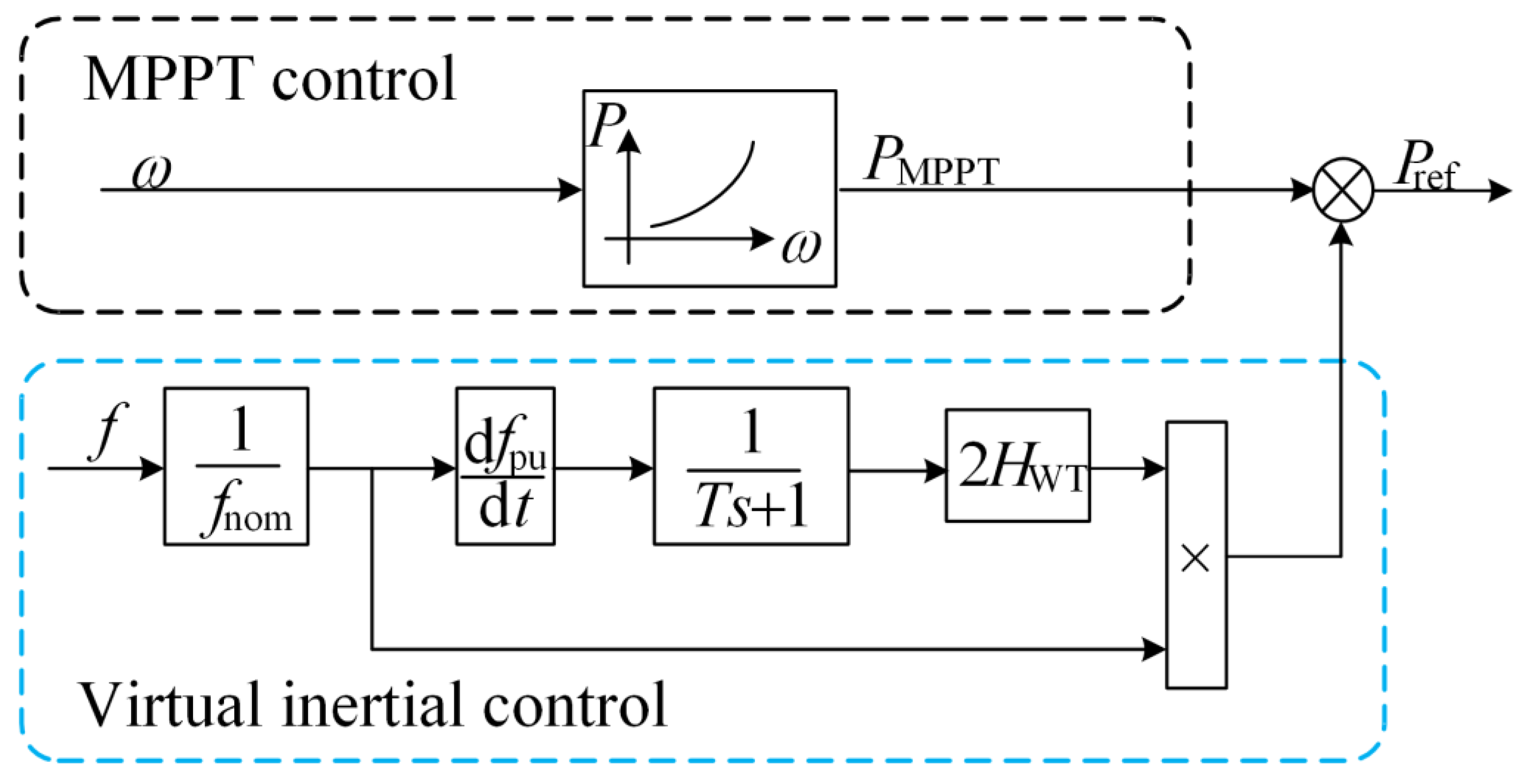
3.2. MPPT Active Output Power under the Influence of Environmental Factors

Under the MPPT control of the output power, WT is mainly decided by the rotor speed. When air density is constant, the speed of the fan is one of the best is a fixed value. However, since the environment is variable, it is necessary to consider the variation of the optimal speed and kopt in the case of changing air density, which affects the output power of the MPPT mode.
The environmental factors affecting air density are air pressure, temperature, altitude, and humidity [26]. In this paper, only the effects of temperature and air pressure are considered, assuming that the terrain distribution of the wind farm is flat, and the consequences of altitude and humidity are not considered for the time being.
According to the IEC 61400-12-1 standard [27], the air density equation is:
ρ = P R 0 T
where T is the average ambient temperature measured every 10 min, calculated by taking T = TC + 273.15; TC is the actual temperature value; P is the average air pressure measured every 10 min; and R0 is dry air gas constant, taking the value of 287.05 J/kgK.
From Equation (29) and Equation (2), air density decreases as temperature increases, and at the same temperature, air density increases with increasing air pressure. As the air density increases, the MPPT output power of the WT increases, and the MPPT output curve is shifted because of the change of kopt, which does not affect the rotational speed, i.e., the rotational speed at the maximum output power corresponding to different air densities is consistent. The monitoring of the air density change is to realize the real−time tracking record of the MPPT curve. Otherwise, the WT should operate according to the MPPT curve at the current air density, resulting in the WT output not being the optimal power.
The allocation methodology in this paper has the following innovations compared to previous allocation methods.
(1)
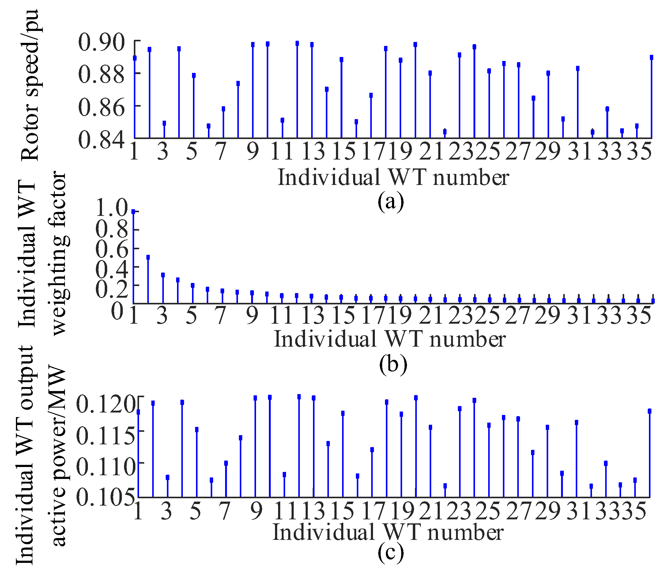
The rotor speed is used as a weighting factor for the allocation, and the difference in speed between units is utilized to enhance the active output power of the turbine.
(2)
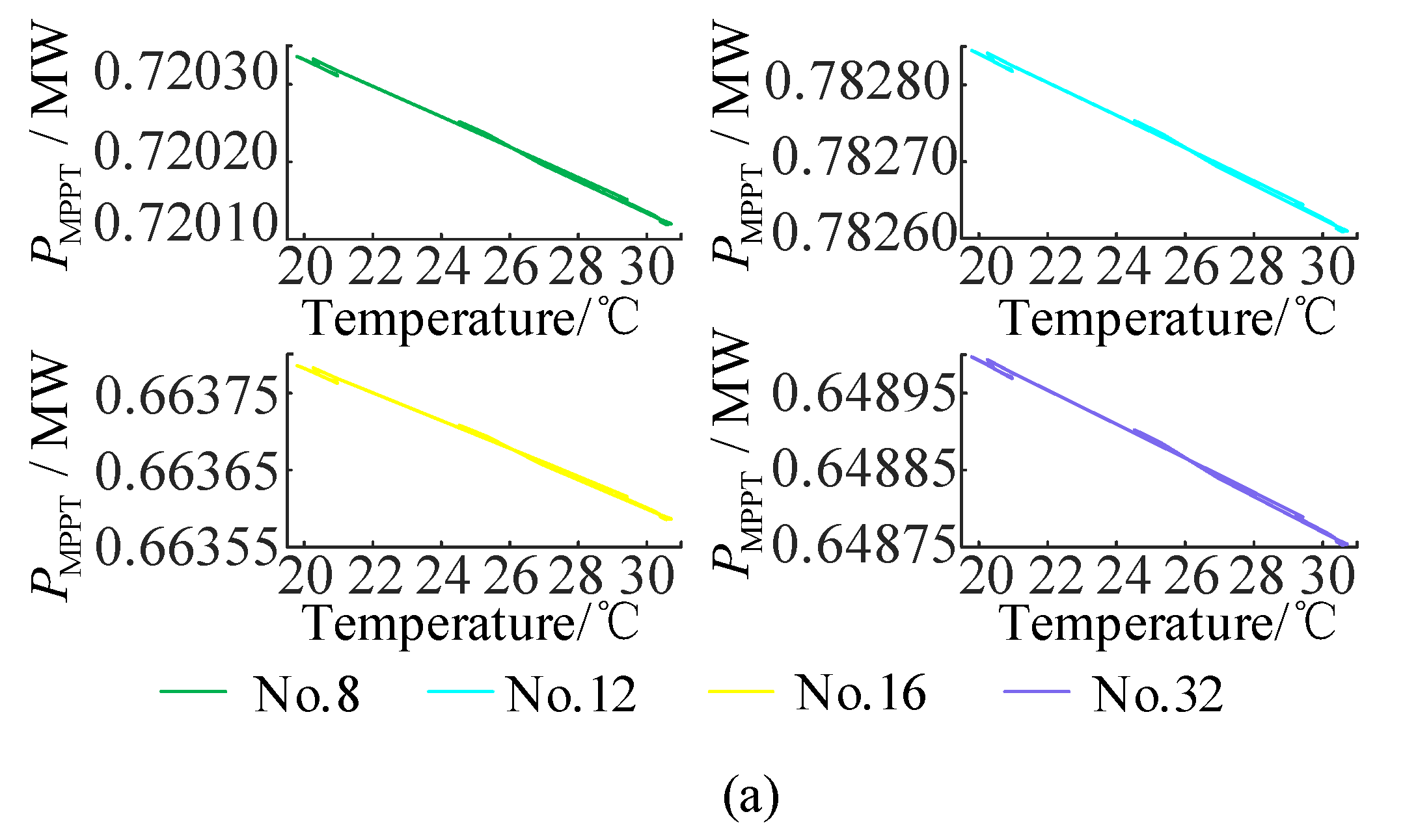
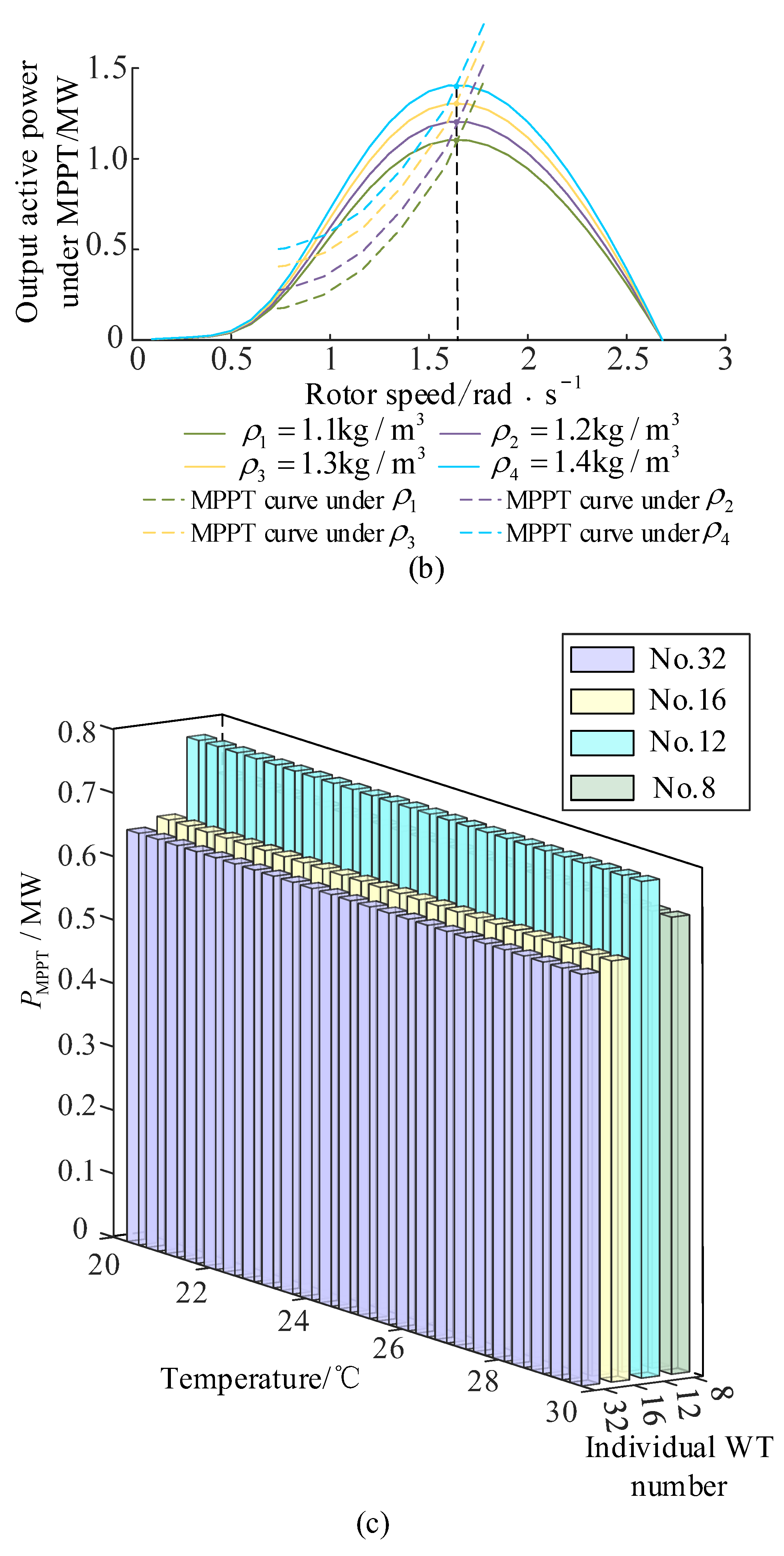
Consider the effect of environmental factors on the MPPT curve and correct the offset of the MPPT curve in a timely manner.

4. Simulation

To verify the validity of the method, a three-machine, nine-node system topology is constructed in the MATLAB/Simulink platform as shown in Figure 3, including two DFIG wind farms, W1 and W2, and one synchronized generator and load. Set the DFIG grid-connected cut-in wind speed vmin to 3 m/s, cut-out wind speed vmax to 25 m/s, and rated wind speed v0 to 11 m/s. The detailed simulation parameters of the WTGs are shown in detail in Table 1. The wind farm W1 contains 36 units of 1.5 MW DFIGs, and the wind farm W2 includes 50 units of 1.5 MW DFIGs. Assuming that the wind farm is flat and distributed, the output power of the wind farm is allocated first and then to the turbines in the field. The capacity of the two wind farms in the system totals 129 MW, and the capacity of the conventional synchronous generator is 400 MW, the load totals 466 MW, and the wind penetration rate is 24.39%.

4.1. Active Power Allocation Results under Sudden Load Increase

In the medium-wind zone, the wind speed is 9 m/s and load 1 is set to surge at the tenth second by 0.08 pu. Currently, the minimum inertia demand of the system Hmin is 4 s. The W1 and W2 rotational speeds and the virtual inertia outputs after the allocation are shown in Figure 4, with q1 = 0.491, q2 = 0.509, ΔP1 = 5.063 MW, and ΔP2 = 5.257 MW, which, in turn, allocates the W1 output power of each machine in the wind farm. However, ΔP1* > ΔP2* in Figure 4 under the standardized value is due to the different rated capacities of W1 and W2 wind farms with different baseline values.
Figure 5 shows the simulation results of the W1 wind farm. The frequency of the W1 grid connection point falls to 49.823 HZ from the tenth second. Currently, the active output power under the VIC of the W1 wind farm is 0.098 pu, and the rotor speed falls from 0.9 pu to 0.842 pu.

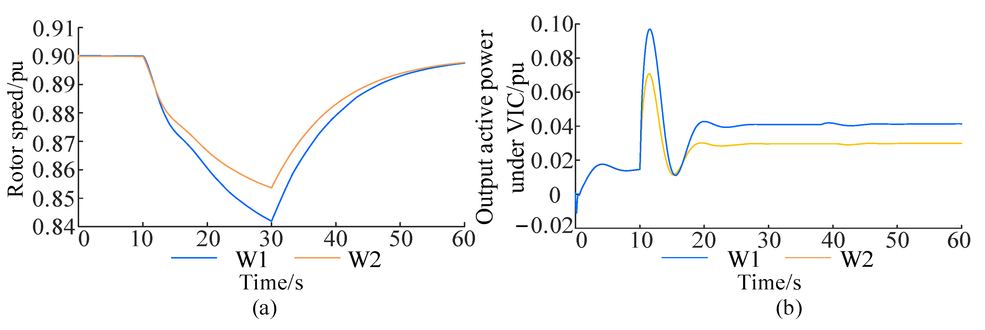
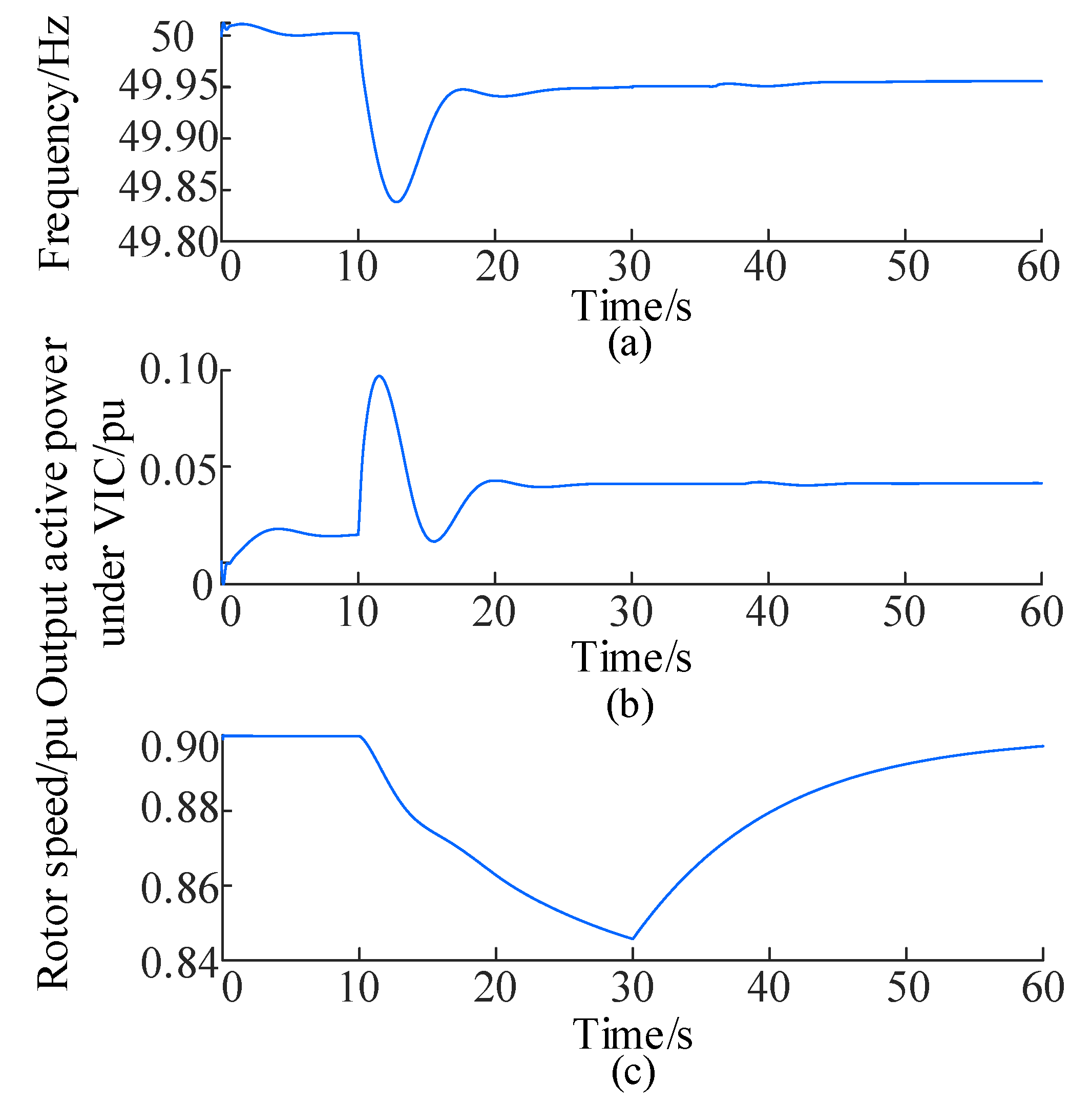
4.1.1. Active Output Power under VIC of a Single

According to the total virtual inertia of the W1 wind farm, there is a further single WT allocation. Considering the different speeds of different single machines, the allocation is implemented based on the rotor speed of the single machine and the proposed strategy. To highlight the effectiveness of the allocation method, the rotor speed of the WT is randomly taken in the rotor speed range of Figure 5c, as shown in Figure 6.
From Figure 6, when the W1 wind farm needs the fan to provide virtual inertia, the virtual inertia output of a single machine is allocated following the fan rotor speed. A single turbine with a high rotor speed has a higher output, while a single turbine with a low rotor speed has a lower output. The No. 12 turbine speed is 0.898 pu, and the virtual inertia is 0.121 MW. The No. 32 turbine has a speed of 0.844 pu, and the virtual inertia is 0.107 MW. HW1 is 4.05 s, and the sum of inertia time constants of the WTGs providing virtual inertia support is 4.13 s, satisfying ∑Hj > HW1. The equivalent inertia time constant Heq of the system is 4.029 s to meet the minimum inertia requirement. This is because the contradiction between the speed controller and the inertia response is alleviated after allocation. The active output power of the single machine is optimized, the output power of virtual inertia is increased, and the inertia time constant of the single machine is also increased.

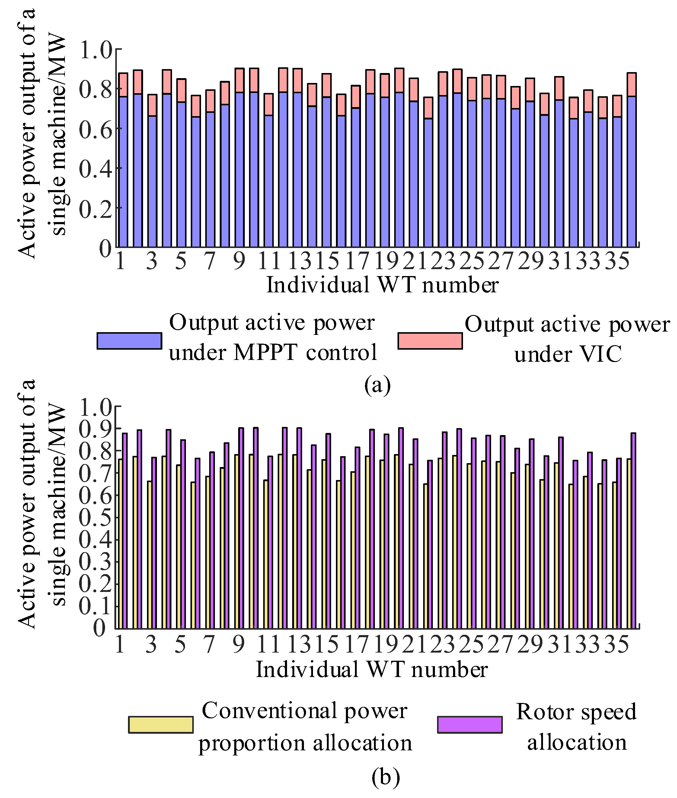
4.1.2. Active Output Power under MPPT Control

The simulation results of four single turbines randomly selected in an area of the W1 wind farm at 24 h temperature on the summer solstice of 2022 in Urumqi City are shown in Figure 7. As the temperature and barometric pressure change, the air density changes accordingly, which, in turn, affects the output power of the WT under MPPT control. The PMPPT gap is further made larger due to the inconsistency in the speed of the DFIG single machine.
From Figure 7a, the output power under MPPT control of each single machine decreases with the increase of temperature in a consistent trend. Figure 7c shows that the different rotational speeds cause the numerical difference in output power between single machines, and Figure 7b reveals that the optimal rotational speed does not change with the change of air density, which is in line with the theoretical analysis, and that the environmental changes do not affect the rotational speed. Still, they will make the MPPT output curve shift.

4.1.3. Adjustable Amount of Active Power of Single DFIG

The magnitude of the virtual inertia output power and the MPPT control output power is inconsistent between the single machines, and the active power output of 36 single machines at 27.144 °C is shown in Figure 8.
It can be seen from Figure 8a that the WT with higher speed has higher output power under MPPT control. In this paper, the power allocation of the virtual inertia of the WT is only linked to speed, and the higher the speed, the greater the virtual inertia allocation value of the single machine. From Figure 8b, taking the thirteenth WT as an example, the traditional power proportional allocation of 0.781 MW is allocated with the method of this paper, and the active output adjustable amount is 0.903 MW. Although the allocation method of this paper is analogous to the traditional power proportional allocation, the maximum active output of a single WT is considered the target based on rotor rotational speed to use the captured wind power fully. In this paper, the active power output of a single machine in this method is greater than that of the traditional method, effectively improving the wind energy utilization rate.

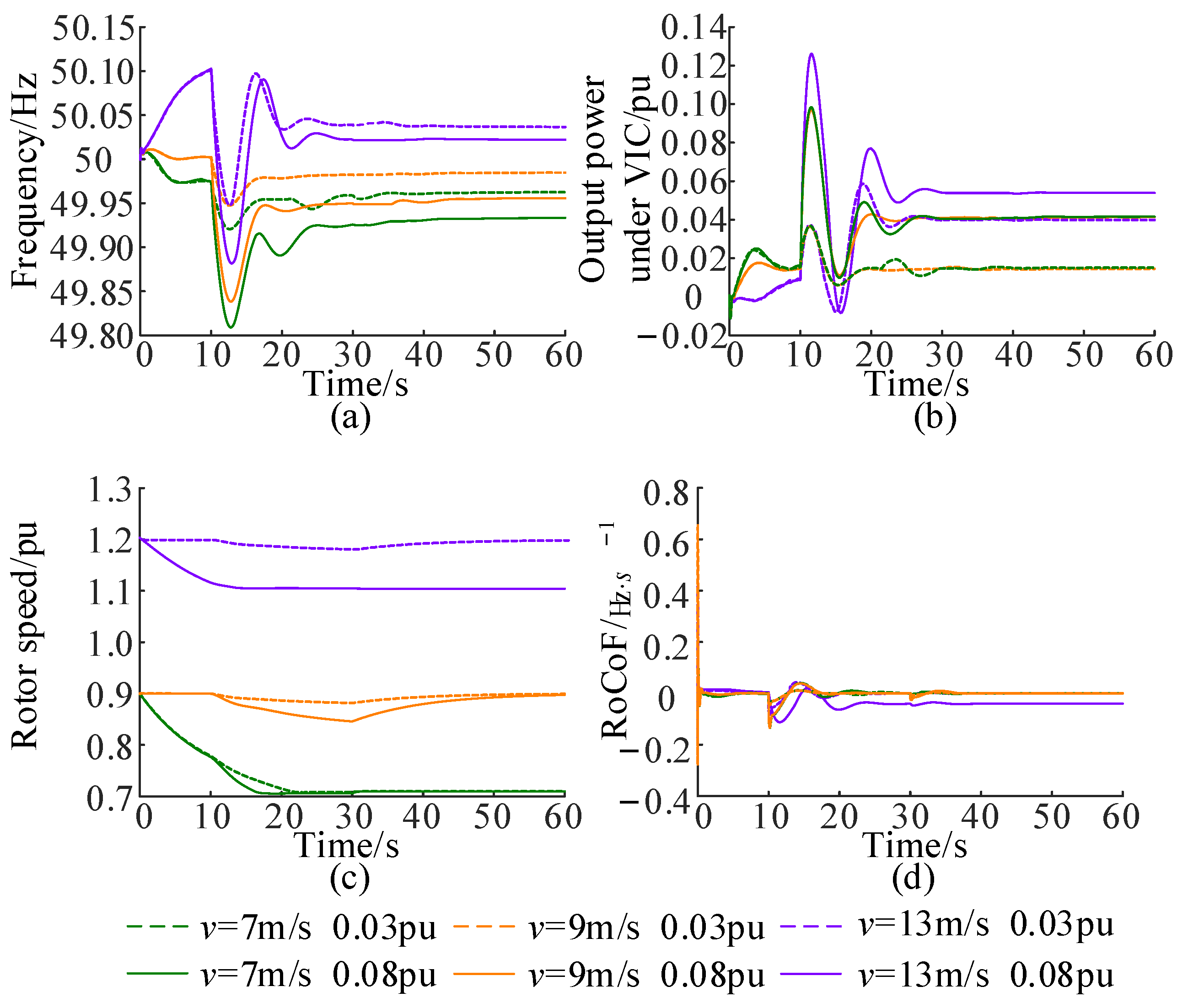
4.2. DFIG Inertia Support Capacity at Different Wind Speeds

According to the previous analysis, the DFIG inertia support capacity is different under different wind speeds, and its support capacity is linked to the wind speed, turbine rotational speed, and the amount of active inequality. The effects of various active inequality measures on the inertia support capacity at different wind speeds are shown in Figure 9.
Figure 9 shows that when the wind speed is 7 m/s, the virtual inertia output power is lower when the unbalanced power fluctuation is 0.03 pu and 0.08 pu. The low wind speed leads to the low rotor speed, and the rotor speed is close to the minimum after being affected. The power fluctuation is larger (0.08 pu), leading the rotor speed to fall close to the critical minimum. The frequency may be a secondary fall phenomenon. According to Figure 9b, the wind speed is small. The DFIG inertia support ability is poor when the power fluctuation is large. The DFIG inertia support capacity is lacking when the power fluctuation is large. When the wind speed is 9 m/s, the DFIG provides the output power of inertia support according to the power fluctuation. The rotor speed is in the normal operation range, the frequency has no secondary drop phenomenon, and the power perturbation of 0.03 pu and 0.08 pu can provide the corresponding power of inertia support, which indicates that the DFIG inertia support capacity meets the system demand at this wind speed. When the wind speed is 13 m/s, the high wind speed leads to high rotor speed, and the DFIG is fully equipped with inertia support capability within the upper limit of the speed; according to Figure 9a,b, it shows that under the same power perturbation, the higher the wind speed, the more the inertia support power can be provided.

4.3. Effect of Active Power Allocation on Inertia Support Capacity

Three different methods are compared in Figure 10:
Case A: no inertia support.
Case B: inertia support without active power allocation.
Case C: inertia support with active power allocation (proposed method).
As can be seen from Figure 10, when the WTGs have no inertia support for the system, the lowest point of the system frequency is clearly lower than that of the WTGs with inertia support capability, and the RoCoF of the system is larger, which implies that the system is weaker in terms of anti-disturbance capability. When the WTGs all have inertia support capability, the WTGs, after active power allocation, improve the transient frequency characteristics of the system through the active power allocation so that the inertia response of each wind farm and the single WT in the field meet the minimum inertia requirements of the system, taking into account the differences between the units, and improve the frequency response characteristics while avoiding the frequency of the second fall. The system frequency minimum after active power allocation (red solid line) is higher than that without active power allocation (green dashed line) in Figure 10a, and the frequency change rate of this paper’s method in Figure 10b is substantially reduced compared with the case without inertia support. Compared with the inertia-supported no-active power allocation, the secondary frequency drop is avoided. Additionally, the RoCoF is also slightly reduced, which proves the validity of the proposed method.

5. Discussion

(1)
The large-scale access of wind power to the grid causes the system inertia to decrease, and the stable operation of the system is threatened. To improve the inertia support ability of wind turbines to the system, an active power allocation method based on rotor speed is proposed. The findings indicate that the proposed method improves the active power output from a single wind turbine and enhances the inertia support capability of doubly fed wind turbines to the system.
(2)
Figure 8 shows the comparison with the conventional distribution scheme, which shows a significant increase in the active power output from a single turbine. This is because the allocation in this paper utilizes the difference in rotational speed between the units to enhance the output power. Figure 10 shows the comparison with and without the allocation scheme, and the system frequency characteristics can be improved by power allocation, while the inertia support capacity is enhanced. The allocation scheme proposed in this paper improves in two aspects, namely, single unit active power output and inertia support, compared to the previous scheme.
(3)
The allocation scheme proposed in this paper is based on rotor speed, which is affected by wind speed. Only the control of the WTGs themselves in the medium and high wind speed zones can satisfy the allocation, while in the low wind speed zones, the turbine outputs less active power due to the low wind speed. Therefore, additional equipment such as energy storage is required.
(4)
In the next step of the study, it is considered that wind farms fulfill the system inertia requirements with the help of energy storage devices in low wind speed areas. In the case of using energy storage, the optimal cost is found by comparing the economic cost of different allocation schemes.
(5)
There is abundant space for further progress in analyzing the power allocation of wind farm clusters and energy storage aggregation stations to achieve the flexible deployment of resources to support stable system operation.

6. Conclusions

In this paper, to make DFIGs enhance the inertia support capability of the system, a rotor speed-based active power allocation method for DFIGs is proposed. VIC is attached to the WT, and the goal is to meet the minimum inertia demand of the system as a constraint and to improve the inertia support capability and overall active output of the wind farm. The turbine speed is used as the allocation index to establish the inertia allocation weight factor. The power command is allocated to each single machine according to the weight, and the main research conclusions are as follows:
In the medium-to-high wind speed region, the method proposed in this paper utilizes the speed difference between units to increase the active power output of a single unit and improve the inertia support of the turbine to the system.
The benefits of this paper can be summarized as follows.
(1)
The allocation method makes full use of the inertia regulation capability of a single turbine, which improves the frequency characteristics of the system and increases the frequency nadir.
(2)
In the speed recovery stage, considering the inertia and speed constraints of the wind farm under the current wind speed, the frequency secondary drop can be avoided.

Author Contributions

Methodology, M.L. and F.L.; Validation, M.L.; Formal analysis, M.L. and F.L.; Investigation M.L. All authors have read and agreed to the published version of the manuscript.

Funding

This research was funded by the Xinjiang Uyghur Autonomous Region of China, grant number 2022B01016.

Data Availability Statement

Data are unavailable due to privacy.

Conflicts of Interest

The authors declare no conflict of interest.

References

  1. Prabhakar, K.; Jain, S.K.; Padhy, P.K. Inertia estimation in modern power system: A comprehensive review. Electr. Power Syst. Res. 2022, 211, 108222. [Google Scholar] [CrossRef]
  2. Zuhuri, B.; Mossavar-Rahmani, F.; Behgounia, F. Chapter 14—Renewable Energy; Elsevier: Amsterdam, The Netherlands, 2022; pp. 423–463. Available online: https://www.sciencedirect.com/science/article/abs/pii/B9780323951128000143?via%3Dihub (accessed on 15 July 2022).
  3. Wang, P.; Zhong, P.; Yu, M.; Pu, Y.; Zhang, S.; Yu, P. Trends in energy consumption under the multi-stage development of ICT: Evidence in China from 2001 to 2030. Energy Rep. 2022, 8, 8981–8995. [Google Scholar] [CrossRef]
  4. Global Wind Energy Council. GWEC Global Wind Report 2023. Available online: http://gwec.net/globalwindreport2023/ (accessed on 10 April 2023).
  5. Dreidy, M.; Mokhlis, H.; Mekhilef, S. Inertia response and frequency control techniques for renewable energy sources: A review. Renew. Sustain. Energy Rev. 2017, 69, 144–155. [Google Scholar] [CrossRef]
  6. Heylen, E.; Teng, F.; Strbac, G. Challenges and opportunities of inertia estimation and forecasting in low-inertia power systems. Renew. Sustain. Energy Rev. 2021, 147, 111176. [Google Scholar] [CrossRef]
  7. Saha, S.; Saleem, M.I.; Roy, T.K. Impact of high penetration of renewable energy sources on grid frequency behaviour. Int. J. Electr. Power Energy Syst. 2023, 145, 142–615. [Google Scholar] [CrossRef]
  8. El-Bahay, M.H.; Lotfy, M.E.; El-Hameed, M.A. Computational Methods to Mitigate the Effect of High Penetration of Renewable Energy Sources on Power System Frequency Regulation: A Comprehensive Review. Arch. Comput. Methods Eng. 2022, 30, 703–726. [Google Scholar] [CrossRef]
  9. Guillamón, A.F.; Lázaro, E.G.; Muljadi, E.; García, Á.M. Power systems with high renewable energy sources: A review of inertia and frequency control strategies over time. Renew. Sustain. Energy Rev. 2019, 115, 109369. [Google Scholar] [CrossRef]
  10. Suo, D. Research on primary frequency modulation control strategy of wind power based on energy storage. J. Phys. Conf. Ser. 2022, 2237, 012021. [Google Scholar] [CrossRef]
  11. Li, C.; Zhang, Z.; Li, J.; Ma, Y.; Zou, J. Design of Control Strategy and Effect Evaluation for Primary Frequency Regulation of Wind Storage System. Front. Energy Res. 2021, 9, 739439. [Google Scholar] [CrossRef]
  12. Gao, Z.; Cao, Y.; Zhang, H.; Qin, H.; Yang, D.; Ma, H. Frequency Control Strategy of DFIGs based on Improved Virtual Inertia Method. IOP Conf. Ser. Earth Environ. Sci. 2021, 838, 012010. [Google Scholar] [CrossRef]
  13. Ma, J.; Jie, H.; Zhou, Y.; Shao, H.; Zhao, S.; Du, Y.; Wang, J.; Sun, S.; Huang, Y.; Shen, Y. A low frequency oscillation suppression method for grid-connected DFIG with virtual inertia. Int. J. Electr. Power Energy Syst. 2023, 144, 108531. [Google Scholar] [CrossRef]
  14. Liu, J.; Yang, Z.; Yu, J.; Huang, J.; Li, W. Coordinated control parameter setting of DFIG wind farms with virtual inertia control. Int. J. Electr. Power Energy Syst. 2020, 122, 106167. [Google Scholar] [CrossRef]
  15. Hazari, M.R.; Mannan, M.A.; Muyeen, S.M.; Umemura, A.; Takahashi, R.; Tamura, J. Fuzzy Logic based Virtual Inertia Control of DFIG based Wind Generator for Stability Improvement of Hybrid Power System. IEEJ Trans. Power Energy 2018, 138, 733–744. [Google Scholar] [CrossRef]
  16. Zhang, X.; Wang, Y.; Fu, Y.; Xu, L. A novel method for obtaining the virtual inertial response of DFIG-based wind turbines. Wind Energy 2015, 19, 313–328. [Google Scholar] [CrossRef]
  17. Xu, B.; Zhang, L.; Yao, Y.; Yu, X.; Yang, Y.; Li, D. Virtual Inertia Coordinated Allocation Method Considering Inertia Demand and Wind Turbine Inertia Response Capability. Energies 2021, 14, 5002. [Google Scholar] [CrossRef]
  18. Zhang, X.; Chen, Y.; Wang, Y.; Zha, X.; Yue, S.; Cheng, X.; Gao, L. Deloading Power Coordinated Distribution Method for Frequency Regulation by Wind Farms Considering Wind Speed Differences. IEEE Access 2019, 7, 122573–122582. [Google Scholar] [CrossRef]
  19. Conrey, J.F.; Waston, R. Frequency response capability of full converter wind turbine generators in comparison to conventional generation. IEEE Trans. Power Syst. 2008, 23, 649–656. [Google Scholar] [CrossRef]
  20. Deng, H.M.; Tang, L.L.; Wu, X.G.; Qiao, Y.; Liu, F. Active power control strategy of wind farms based on wind turbine regulation ability ranking. Power Syst. Technol. 2018, 42, 2577–2584. [Google Scholar]
  21. Wang, Z.; Gao, J.; Zhao, B.; Ding, L.; Cao, Y. Wind farm virtual inertia coordinated control technology based on wind speed prediction. Acta Energiae Solaris Sin. 2022, 43, 138. [Google Scholar]
  22. Meng, X.; Liu, J.; Liu, Z. A generalized droop control for grid-supporting inverter based on a comparison between traditional droop control and virtual synchronous generator control. IEEE Trans. Power Electron. 2018, 34, 5416–5438. [Google Scholar] [CrossRef]
  23. Chen, Y.; Zhuo, Y.; Liu, Y.; Guan, L.; Lu, C.; Xiao, L. Development and recommendation of fast frequency response market for power system with high proportion of renewable energy. Autom. Electr. Power Syst. 2021, 45, 174–183. [Google Scholar]
  24. State Administration for Market Regulation; Standardization Administration of China. Technical Specification for Connecting Wind Farm to Power System—Part 1: On Shore Wind Power. 2021. Available online: http://c.gb688.cn/bzgk/gb/showGb?type=online&hcno=F0127C2B431AC283CD6ED17CE67F8E46 (accessed on 20 August 2021).
  25. Jensen, N.O. A note on wind generator interaction. In Roskilde, Denmark: Risø National Laboratory; Risø National Laboratory: Roskilde, Denmark, 1983; Volume 2411. [Google Scholar]
  26. Picard, A.; Davis, R.S.; Gläser, M.; Fujii, K. Revised formula for the density of moist air (CIPM-2007). Metrologia 2008, 45, 149. [Google Scholar] [CrossRef]
  27. IEC 61400-12-1; Part 12-1: Power Performance Measurements of Electricity Producing Wind Turbines. IEC (International Electrotechnical Commission): Geneva, Switzerland, 2005.
Figure 1. Virtual inertia control block diagram.
Electronics 13 00279 g001
Figure 2. Power–speed response curve of DFIG rotor kinetic energy control.
Electronics 13 00279 g002
Figure 3. System structure diagram. (a) Grid-connected DFIG structure; (b) System topology.
Electronics 13 00279 g003
Figure 4. Wind farm simulation results. (a) Rotor speed; (b) Output active power under VIC.
Electronics 13 00279 g004
Figure 5. W1 wind farm simulation results. (a) W1 frequency response; (b) Output active power under VIC; (c) Rotor speed.
Electronics 13 00279 g005
Figure 6. Single DFIG virtual inertia active output power allocation results. (a) Rotor speed; (b) Weighting factor; (c) Output power under VIC.
Electronics 13 00279 g006
Figure 7. MPPT output power of single DFIG on summer solstice. (a) Trend of single machine output with temperature at different speeds; (b) PMPPT-ω curves for different air densities; (c) MPPT output of DFIG with different speeds.
Electronics 13 00279 g007aElectronics 13 00279 g007b
Figure 8. Adjustable active power of a DFIG. (a) Active power output of a single machine; (b) Comparison of different allocation methods.
Electronics 13 00279 g008
Figure 9. Comparison of inertia response under different wind conditions. (a) Frequency; (b) Output active power under VIC; (c) Rotor speed; (d) RoCoF.
Electronics 13 00279 g009
Figure 10. Comparison of the scenarios. (a) Frequency; (b) RoCoF.
Electronics 13 00279 g010
Table 1. Simulation parameters.
ModuleParametersSymbolValue
Wind turbineRotor radiusR/m38.5
Optimal wind energy utilization factorCpopt0.4335
Optimal leaf tip speed ratioλopt7.2
Wind speedv/m·s−19
DFIGRated active powerPNA/MW1.5
Rated voltageUNA/V575
Polar logarithmp3
Synchronous generatorRated capacitySNS/MW800
Rated voltageUNS/V18,000
Polar logarithmp1
Inertial time constantHG/s4
Disclaimer/Publisher’s Note: The statements, opinions and data contained in all publications are solely those of the individual author(s) and contributor(s) and not of MDPI and/or the editor(s). MDPI and/or the editor(s) disclaim responsibility for any injury to people or property resulting from any ideas, methods, instructions or products referred to in the content.

