Article

Influence Analysis and Control Method of Ultra-Low Frequency Oscillation in a Hydro-Dominant Sending Power System with Wind Power Integration

1
State Grid Sichuan Electrical Power Research Institute, Chengdu 610041, China
2
Power Internet of Things Key Laboratory of Sichuan Province, Chengdu 610041, China
3
State Grid Sichuan Electric Power Company, Chengdu 610041, China
4
College of Electrical Engineering, Sichuan University, Chengdu 610065, China
*
Author to whom correspondence should be addressed.
Electronics 2024, 13(1), 31; https://doi.org/10.3390/electronics13010031
Submission received: 25 September 2023 / Revised: 5 December 2023 / Accepted: 7 December 2023 / Published: 20 December 2023

Abstract

:
To make clear the influence of renewable energy on ultra-low-frequency oscillation (ULFO) in a hydro-dominant system via an high voltage direct current (HVDC) transmission system, this paper studies the damping characteristics when wind power is integrated into the sending power system. The damping torque method is applied for the mechanism study and risk evaluation of ULFO. The study of the inner cause and outer performance proves that ULFO belongs to frequency oscillation rather than conventional power oscillation. According to the theoretical analysis, the suggested control mode is identified to reduce the risk of ULFO. Moreover, a robust controller is designed for wind units based on mixed H2/H robust control theory, and the control method makes use of the fast response ability of the converter without compromising the primary frequency regulation ability. Finally, a simulation model of a hydro-dominant sending power system with wind integration is established in PSCAD Version 4.6 software. The simulations verify the proposed control can suppress ULFO effectively.

1. Introduction

Hydropower is one of the traditional energy sources that has demonstrated the unique advantages of adapting to contemporary low-carbon emission goals. At the same time, accelerating the penetration of new energy is a significant and imperative pathway all over the world [1]. In this context, integrating renewable energy into hydropower plants becomes an inevitable trend. However, there is a compelling oscillation problem called ultra-low-frequency oscillations (ULFOs). Actually, ULFOs have been successively recorded early in the US Northwest Pacific system, the Canada BC Hydro-Bureau, and the Colombia Power Grid [2,3,4]. In recent years, this problem has attracted more and more attention because it emerged in both the Yunnan Power Grid in 2012 and the Southwest Power Grid in China in 2016, the common feature of which is that the operating condition is asynchronous, interconnecting through back-to-back high-voltage DC transmission systems [5,6].
Unlikely commonly known low-frequency oscillations (LFOs) with oscillation frequencies between 0.1 and 2.5 Hz [7], ULFOs usually oscillate below 0.1 Hz, which means the oscillation period is greater than 10 s [8]. Moreover, the individual reflection is that the frequency would oscillate and last for over half an hour. This imposes enormous challenges on the stable operation of hydro-dominant power systems. Emerging research has been conducted, focusing on the causes and mitigation of ULFO, and some valuable conclusions have been summarized.
For the causes and main factors, the negative damping analysis of hydropower units is found to be the fundamental cause [9]. The complex torque coefficients (CTCs) are deduced to compare the damping of 0–2.5 Hz, and the turbine governor is found to be responsible for ULFOs [10]. To find out the specific factors, reference [11] investigates the governing system’s parameters. It seems that the proportional and integral coefficients of the PID controller and water starting time determine the damping level of the power system together. Meanwhile, reference [12] obtains similar conclusions based on trajectory eigenvalue (TE) theory [13], which can indicate the oscillation frequency and damping ratio. The TE results also prove both the strength of the system connection and thermal-hydropower proportion and are also crucial to affect the oscillation mode [14]. Reference [15] studies the detailed influence of water diversion system topologies and operation scenarios by phase diagrams. Additionally, an interesting discovery is the amplitude of ULFOs had a clear yearly cycle in the Nordic power system over seven years, 2015–2021 [16]. Then, both the cause and factors are verified by an experimental investigation [17]. Obviously, most of the research concerns solely hydropower systems. What is even more thought provoking is that the integration with renewable energy is neglected, but the more remarkable frequency risks of the hydro-wind power system are foreseeable.
According to the cause of ULFO, the corresponding control methods can be designed for oscillation elimination. Basically, there are three types of control methods. The first is to re-tune the PI parameters of the governor properly [18]. For example, robust fixed order control can be designed [19]. To make up for this flaw, some intelligence algorithms, such as ant colony and deep learning algorithms, are applied to ensure the effectiveness of the optimized PID parameters for various extreme operating conditions [6,20]. But, the negative impact is that it may weaken the performance of the governor [21]. The second control method designing is an additional damping controller, where the power system stabilizer (PSS) or governor’s PSS (GPSS) can be developed. Multi-band PSS can be used for either LFO or ULFO suppressions [22]. Additionally, the GPSS can also be configured on the governor to mitigate the negative damping effect [23]. The methods mentioned before involve governor modification in hydropower plants, which are challenging to conduct. The third method uses electronic devices to suppress ULFO. Since the HVDC system is crucial for asynchronous networking, it is rational to take advantage of control abilities, such as a frequency limiting controller (FLC) [24] or a damping controller [25].
However, such studies have not considered more and more renewable energy integration in the modern power system [26]. The mechanism of wind power penetrating to hydro-dominant has not been revealed. Wind power has a significant impact on ULFOs because the inertia will be decreased by the renewable power and the inertia has a huge influence on frequency regulation [27]. On the other side, to decrease the risk of ULFO, the common control method is to apply smaller governor PID parameters, but this weakens the primary frequency control ability. In such a situation, the frequency characteristics will be more complicated. At the same time, compared to physical and mechanical controllers on hydro units, the power electronic devices have the advantage of fast and flexible adjustment ability, which provides opportunities for ULFO control when wind power is integrated [28].
It can be found that renewable wind power’s impact on ULFO is lacking, and there is a need for additional control methods to compensate for the weak frequency control ability. To find the evolution mechanism of ULFO with wind power integration, as well as for the sake of satisfactory control strategy, the contribution of this paper is conducted in two aspects:
(1)
The occurrence scenarios of ULFOs are developed by considering wind power integration. Thus, based on the mechanism of ULFOs in asynchronous hydropower systems, the influence of wind power generators on frequency oscillation is innovatively investigated, and some determined factors are defined, which makes it clearer to deal with the consumption of sustainable wind energy.
(2)
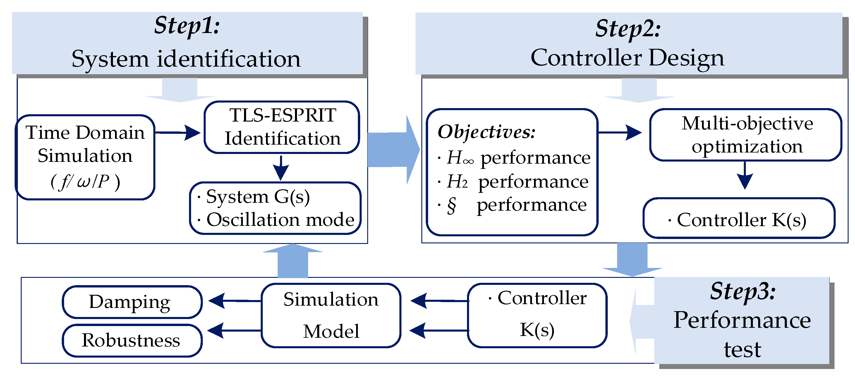
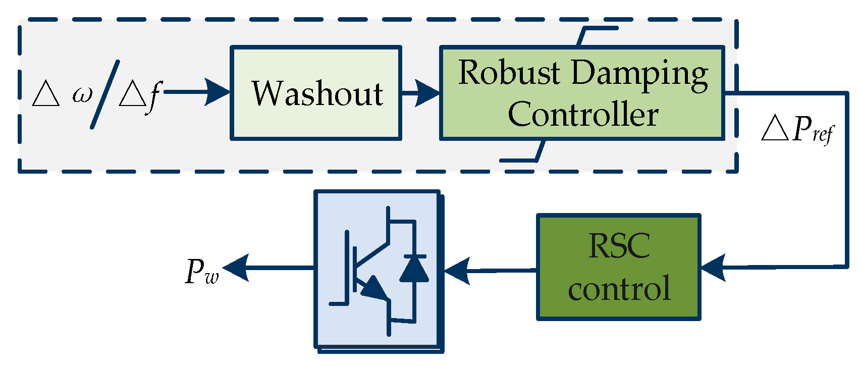
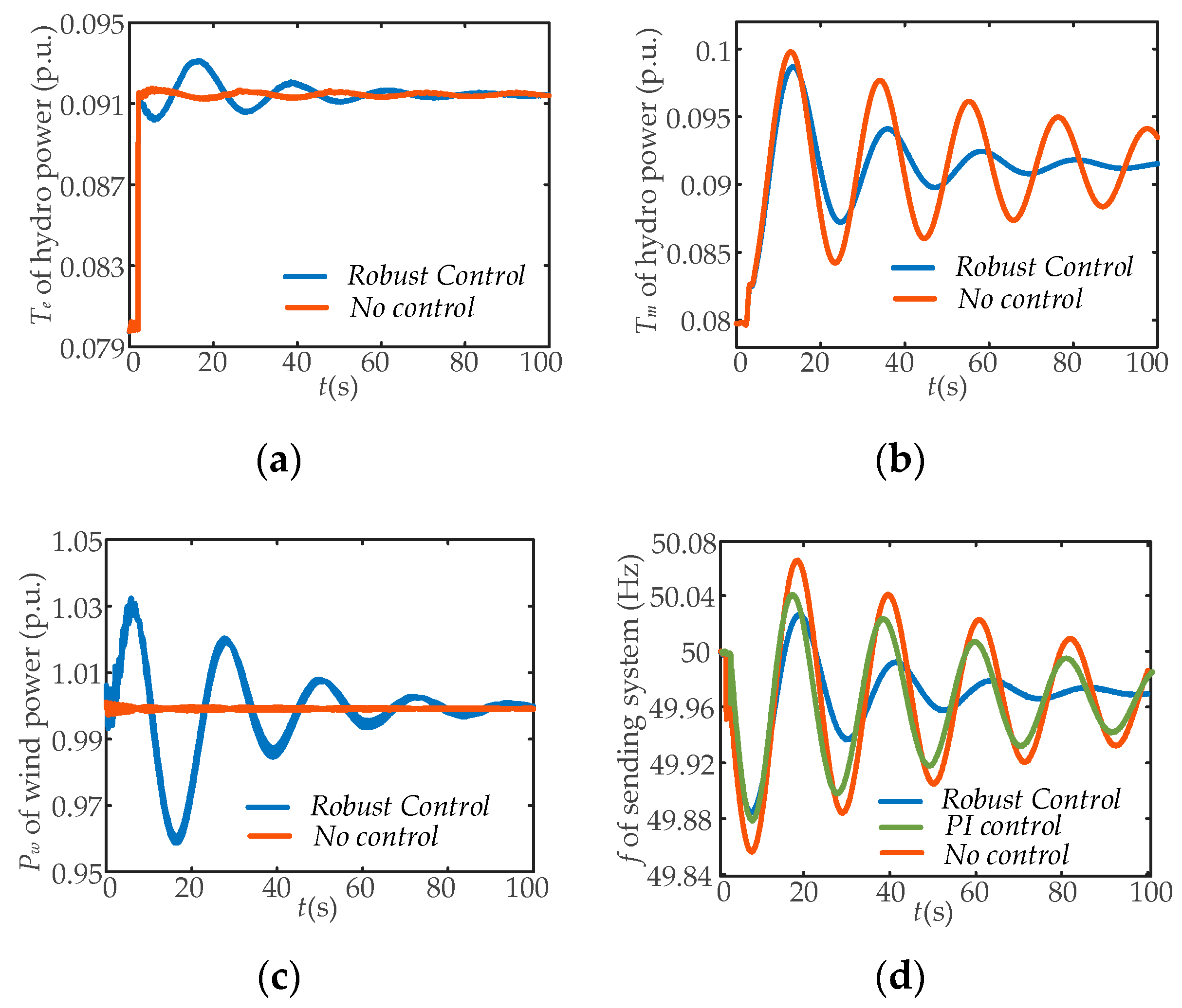
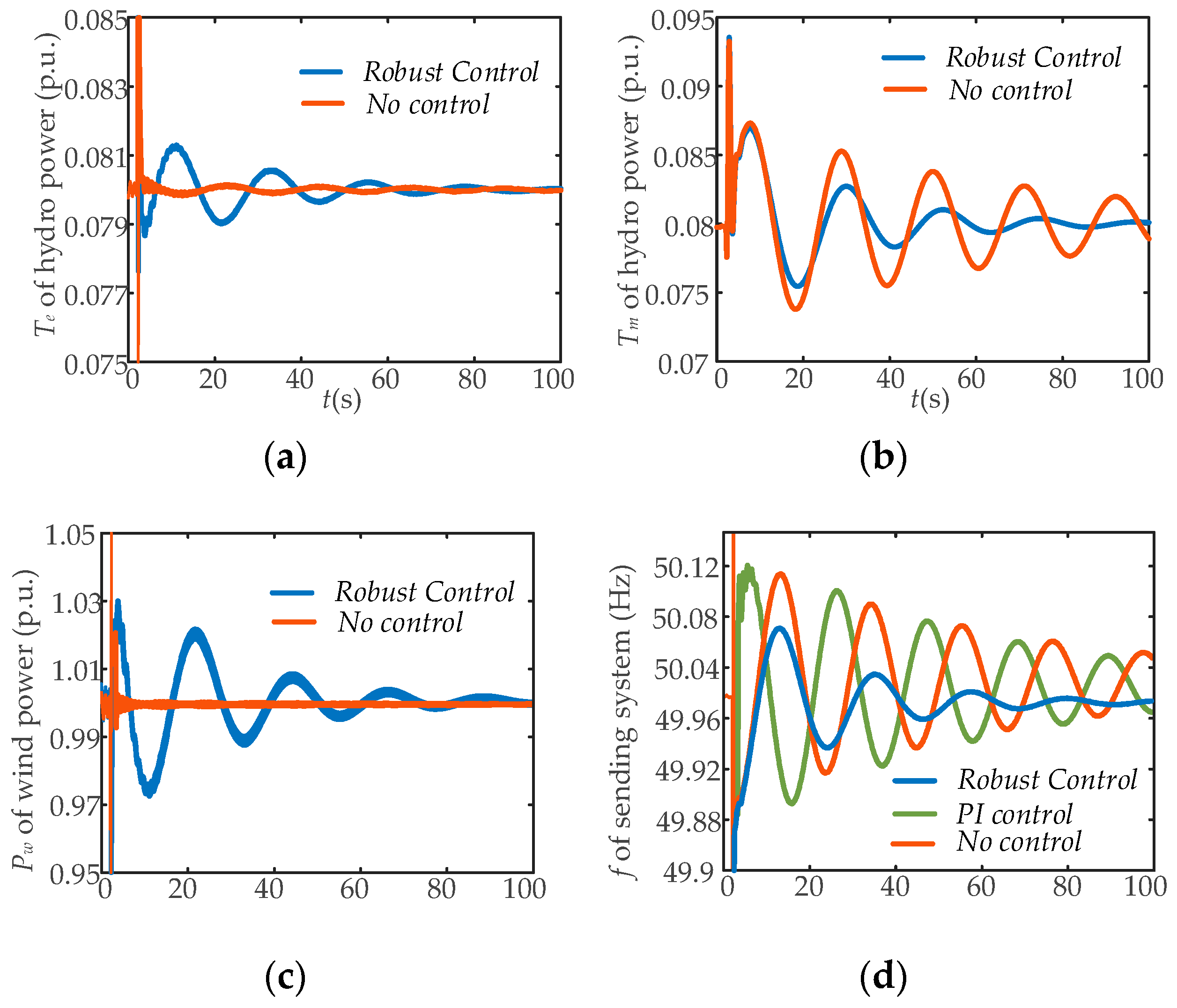
The control method is proposed based on wind power to suppress ULFOs. First, the identification algorithm is utilized to obtain the model of the power system. Then, the additional damping control based on mixed H2/H robust control theory is proposed to strengthen the damping of the sending system. Subsequently, both frequency response performance and frequency oscillation suppression ability can be guaranteed, and this is significant for promoting the stable operation of a low-carbon energy base.
The organization of this paper is as follows. Section 2 establishes a basic mathematical model of the hydropower sending system, and the damping torque is obtained to reveal the mechanism of ULFOs. Section 3 investigates the influence of wind power integration on ULFOs, and the main parameters are defined. Section 4 proposes a coordinated control method of wind power to improve the frequency stability and suppress ULFOs of the sending system. The simulations are conducted to verify the effectiveness of the research in Section 5. Finally, Section 6 concludes this paper.

2. The Mechanism of Ultra-Low-Frequency Oscillation

This section introduces the mechanism of ULFO of hydropower based on damping torque theory, and the key factors influencing the oscillation mode are studied.

2.1. The Hydropower Generator Model

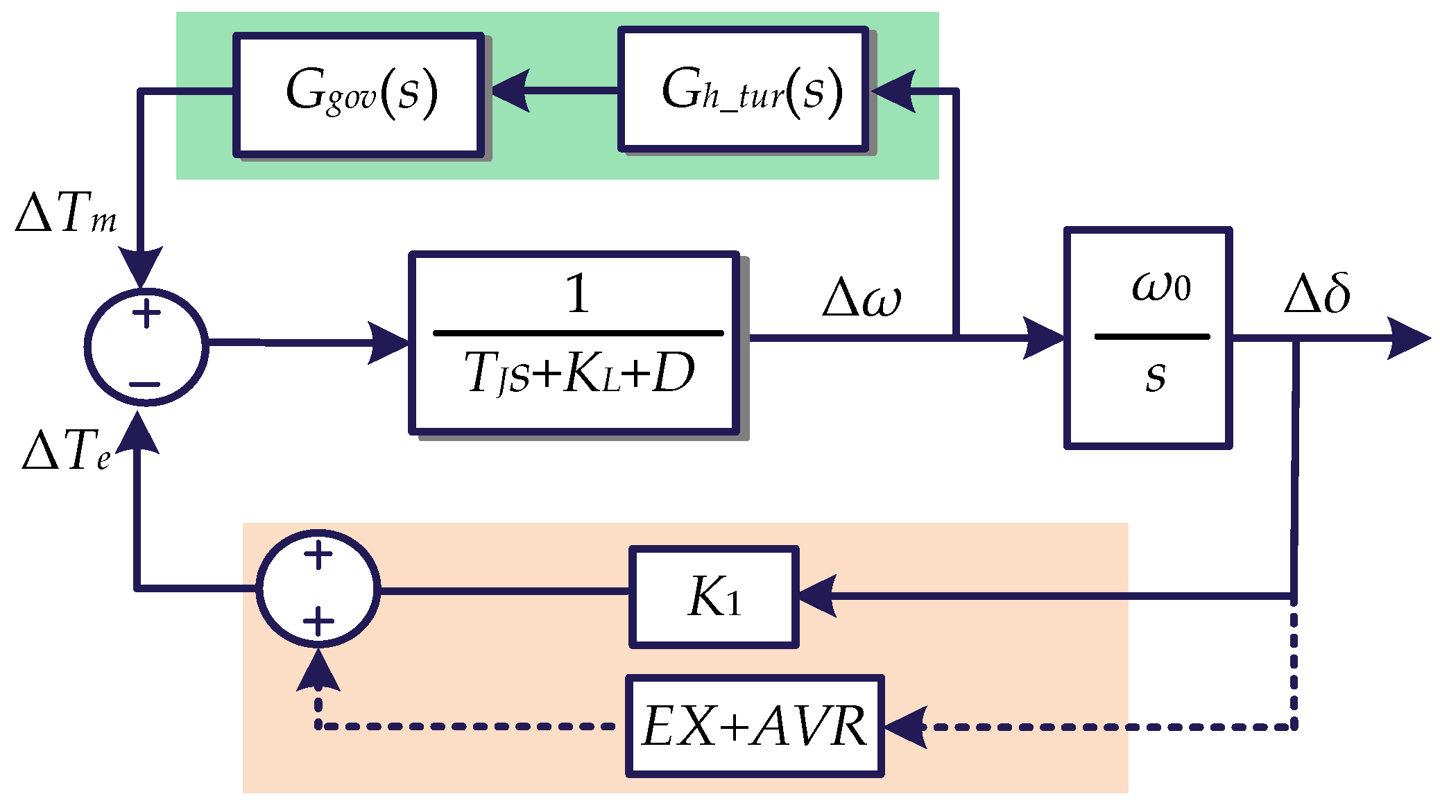
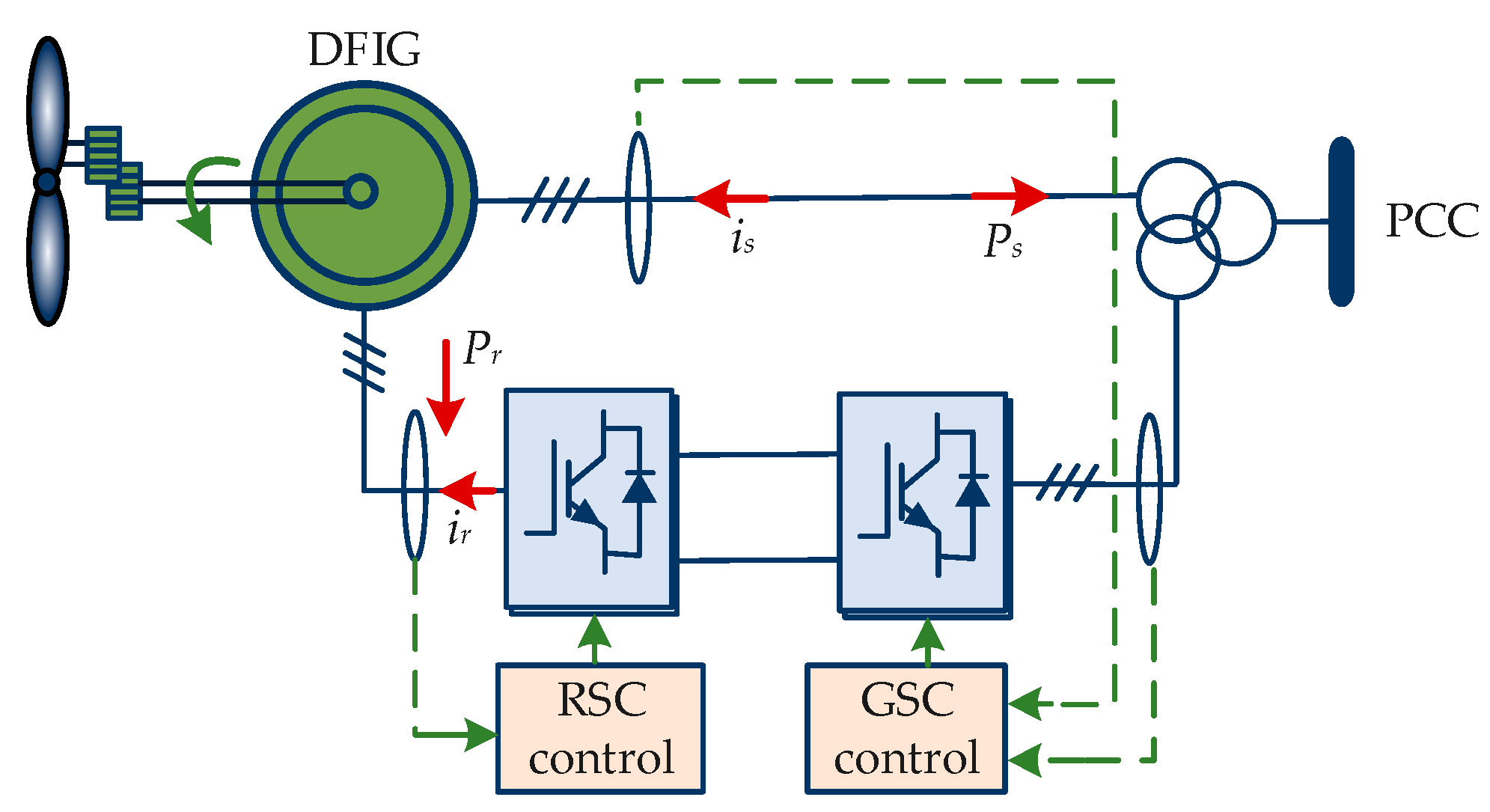
The basic Philips–Heffron model of a hydropower generator is given in Figure 1. There are two parts to determine the output power of the hydro unit, where the mechanical power deviation △Tm is determined by the water turbine and governor in green background and the electromagnetic power deviation △Te is determined by the synchronous generator and excitation loop in orange background. There is Pe = ωTe. Note that the traditional LFO belongs to the active power fluctuation of either the local mode or inter-area mode. However, recent research results prove that ULFO is a kind of frequency stability problem [20]. This means that a simplified way to analyze ULFO focuses more attention on the mechanical part marked green in Figure 1, and the key elements are the hydro turbine and governor. Moreover, compared to the single machine with an infinite bus system (SMIB) for LFO analysis, the effect of load KL is considered significant. Therefore, the dashed lines simplify some of the transfer functions.
The mathematical model can be expressed as:
{ d Δ ω d t = 1 T J ( Δ T m Δ T e D Δ ω ) d Δ δ d t = ω 0 Δ ω Δ T m Δ ω = G g o v ( s ) × G h _ t u r
where Δ represents the deviation of variables, ω is the rotor speed, δ is the power angle, TJ and D are the inertia time constant and damping coefficient of the generator, respectively, and Ggov and Gh_tur express the transfer functions of the turbine and governor, respectively.
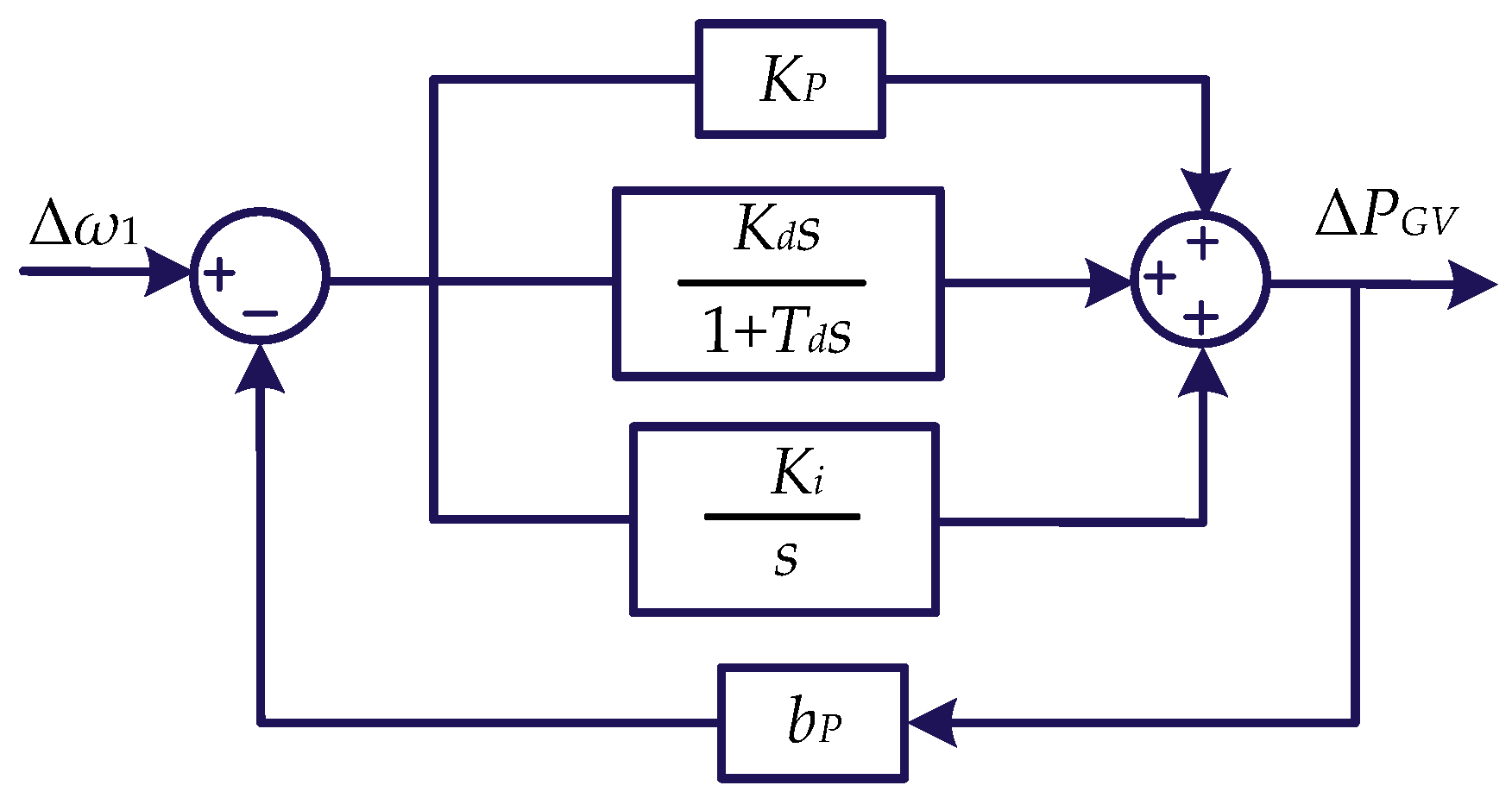
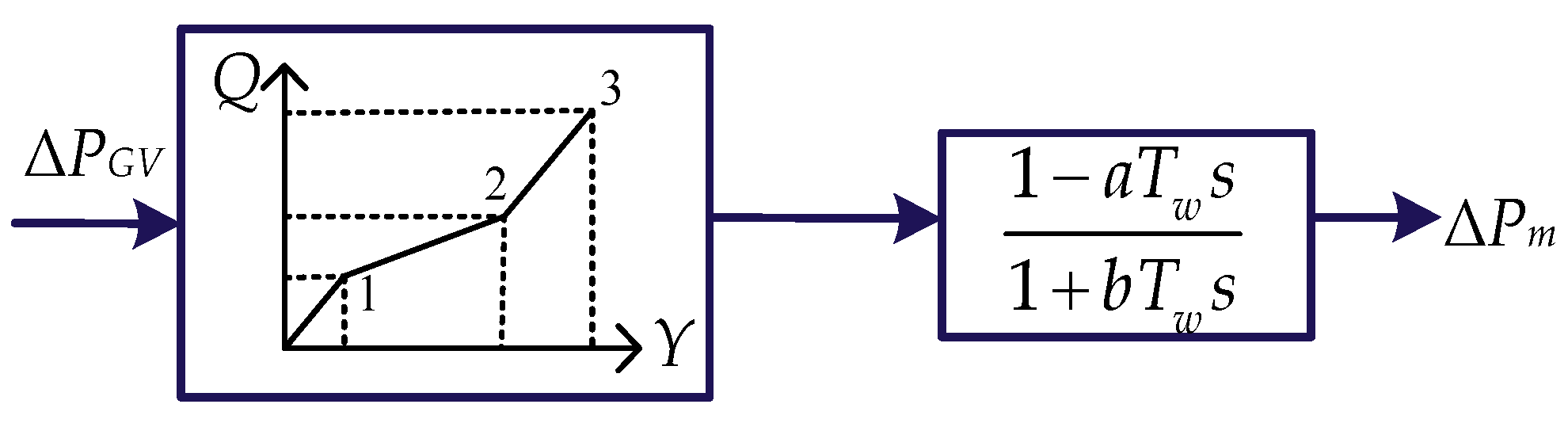
Specifically, the control structures of the hydro turbine and PID governor are depicted in Figure 2 and Figure 3.
Where KP, Ki, and Kd are the proportional, integral, and differential coefficients of the PID governor, bp is the permanent slip coefficient, and PGV is the output of the governor. For hydro turbines, Tw is the water starting time, which can comprehensively reflect the operating condition and is related to the head and discharge of the hydropower unit. Generally, a = 1, b = 0.5.

2.2. The Damping Torque of the Hydropower Unit

The complex torque coefficient method is constantly used to effectively analyze oscillation problems owing to the priority to observe the damping characteristics of multi-bandwidth frequencies visually.
Based on the diagrams in Figure 2 and Figure 3, the transfer functions of the governor and the hydraulic turbine can be presented in (2) and (3).
G g o v ( s ) = ( K p T d + K d ) s 2 + ( K p + K i T d ) s + K i ( b p K p T d + b p K d + T d ) s 2 + ( b p K p + b p K i T d + 1 ) s + b p K i
G h _ t u r ( s ) = 1 T w s 1 + 0.5 T w s
It is important to point out that Tw is regarded as one of the inner causes of ULFO because (3) indicates the hydropower unit is a non-minimum phase system, which is different from thermal power units [13]. This may explain the high occurrence in hydro-dominated power systems.
According to Figure 1, the transfer function of the Δω→ΔTm loop can be obtained. Moreover, based on the complex torque coefficient method, the mechanical torque can be divided into synchronous torque coefficient Ksm and damping torque coefficient KDm, respectively. KDm is related to the capability of the system to suppress oscillations.
G g e n ( s ) = Δ T m Δ ω = G g o v ( s ) × G h _ t u r = K Sm Δ δ + K Dm Δ ω
Substituting s = jω into Ggen(s), the damping torque KDm can be denoted in (5):
K D m = K g 1 K g 3 + K g 2 K g 4 K g 1 2 + K g 2 2
where:
{ K g 1 = [ b p ( K d + K p T d + 0.5 K p T w + 0.5 K i T d T w ) + T d + 0.5 T w ] ω 2 + b p K i K g 2 = 0.5 T w ( b p K p T d + b p K d + T d ) ω 3 +              ( b p K p + b p K i T d + 0.5 b p K i T w + 1 ) ω K g 3 = ( K p T d + K d K p T w + K i T d T w ) ω 2 + K i K g 4 = ( K p T d T w + K d T w ) ω 3 + ( K p + K i T d K i T w ) ω

2.3. The Mechanism Analysis of ULFOs

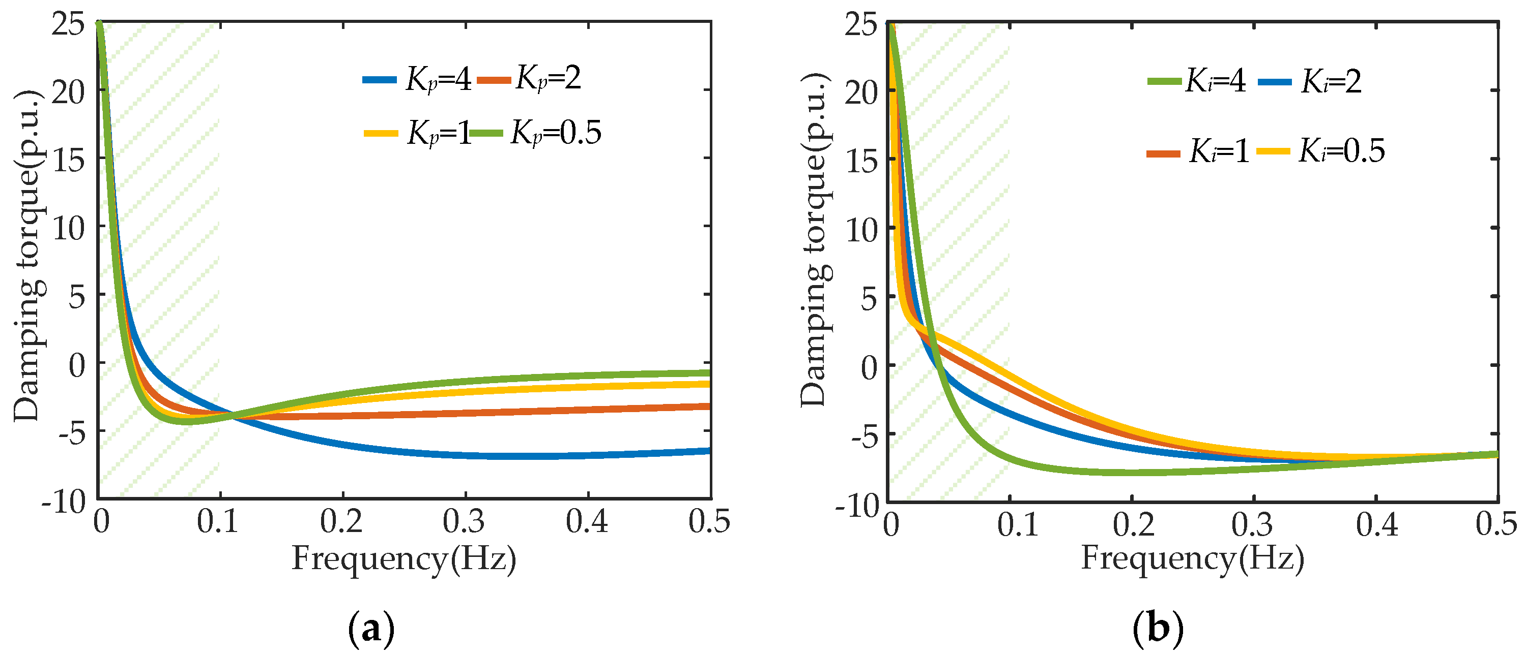
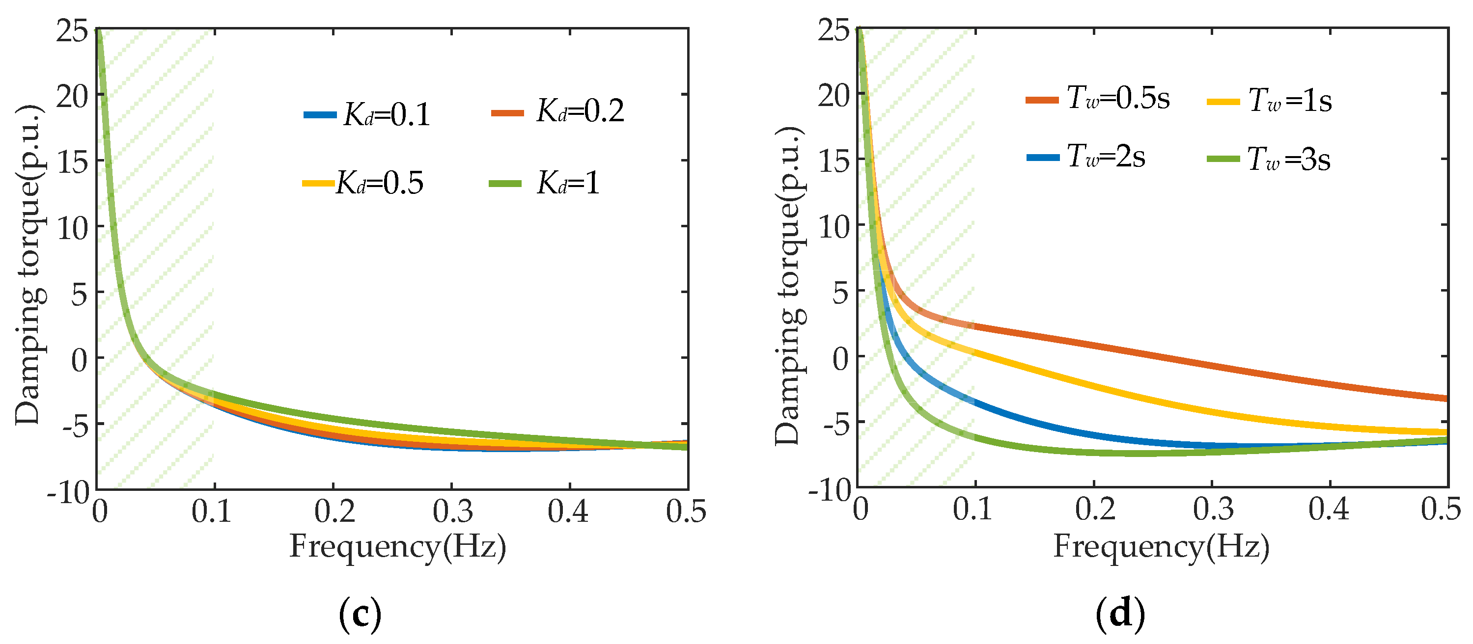
To ensure the cause of ULFO and find the mechanism, the specific essential parameters of the hydropower generator, including KP, Ki, Kd, and Tw, are studied. Note that the values of KP, Ki, and Kd refer to the adjustment range of the governor parameters in the actual hydropower plant. In fact, Kd is set at a minimal value, such as 0.1 or even zero. In this paper, the analysis of Kd is necessary to ensure the dominant influencing factor. The influence of these parameters on damping characteristics is presented in Figure 4. The green background part is the ULFO area.
For the parameters of the PID governor, the influence of KP and Ki is more significant than Kd. The differential coefficient has little effect on both ultra-low-frequency and low-frequency bands. Increasing KP would provide a positive damping for ULFO, while a change in LFO is the opposite. The influence of Ki varies with the oscillation frequency of the system. In an ultra-low-frequency band, there is an intermediate frequency, and the changes in damping on both sides of this frequency are precisely opposite.
For the influence of the hydro turbine, the increases in Tw cause arresting negative damping. Therefore, it can be concluded that a larger water starting time or a long penstock a of hydropower generator would lead to the risk of ULFO in the system. Meanwhile, the improper PID parameter of the hydro governor would further worsen the damping, and the combination of these causes makes it easier to excite ULFO in a hydro-dominated sending system.

3. The Influence of Wind Integration on ULFO in a Hydro-Dominated System

The mechanism of ULFO in a traditional hydro-dominated system is concluded in Section 2. With the rapid development of renewable energy all around the world, there is a need to discuss the integration of wind power. This section further investigates the integration of wind power and the influence of wind power without additional control.

3.1. The Model of a Doubly Fed Induction Generator

The doubly fed induction generator-based wind turbine (DFIG-WT) is integrated into the hydro-dominated system at the point of common coupling (PCC) in this paper. The structure of the DFIG-WT is shown in Figure 5. There are two parts of the control system: a rotor-side converter (RSC) control and a grid-side converter (GSC) control.
According to the operating principle of the DFIG, the total output power Pe, stator power Ps, and rotor power Pr of the DFIG can be expressed as:
{ P s = ω g ω m P e P r = ( 1 ω g ω m ) P e P r P s = ω m ω g ω g
Generally, there is no additional control of the DFIG. Thus, an obvious drawback of the DFIG is its inability to participate in system frequency adjustment. If it is necessary to reform the DFIG to be able to respond to the deviation of frequency in the AC system; a popular approach is droop control or virtual synchronous generator (VSC) control. In the early stages of wind integration, the DFIG may not configure or apply these methods. Thus, in this section, neither droop control nor VSC control is considered in the following discussion.

3.2. The Influence of the Integration of Wind Power on ULFO

There are two ways to integrate the DFIG in a hydro-dominated sending system. One is the capacity of the hydroelectric unit to remain constant, and the overall capacity of the sending system increases with the integration of the DFIG. Another way is that the DFIG could replace hydroelectric units of the same capacity, and the overall capacity of the sending system remains constant. The influence of both ways is discussed.
The operation power of a hydro-dominated sending system with wind integration in these two situations is shown in Table 1.

3.2.1. Constant Capacity of the Hydropower Unit

In constant capacity hydropower (CCH) operation mode, the output power of hydropower generators remains at 820 MW, and the output active power variation with the increasing penetration of wind power is between 0 to 1220 MW. Since there is no additional control of wind turbines, the frequency modulation capability can be neglected in this part. The output power of the hydro units and frequency are shown in Figure 6, Figure 7 and Figure 8. The oscillation modes are given in Table 2.
Comparing Figure 6 with Figure 7, the occurrence of ULFO will cause a greater deviation range of mechanical power than electromagnetic power. Consequently, it is generally characterized by significant fluctuations in frequency; while in LFO, researchers pay more attention to the active power fluctuation.
Based on the analysis results above, the integration of wind power into a hydropower base has relatively more influence on the damping ratio of ULFO than oscillation frequency. The increasing wind power will slightly weaken the damping of the system. Thus, it can be considered that the main negative damping of ULFO is provided by hydropower.

3.2.2. Constant Capacity of the Sending Power System

In constant capacity of sending system (CCS) operation mode, the total power of hydro and wind power remains 1300 MW, and the output active power of both hydropower units and wind power will vary to form different combinations. Moreover, the active power transmitted by the HVDC transmission system is about 1000 MW. The simulations are shown in Figure 9, Figure 10 and Figure 11. The oscillation modes are given in Table 3.
In Table 3, the results indicate that with more wind power integrated to replace hydropower of the sending system, the oscillation frequency of ULFO is almost unchanged (about 0.047 Hz), while it indeed enhances the damping of ultra-low frequency, which is beneficial for ULFO suppression. Moreover, in Figure 9 and Figure 10 due to the changing capacity of hydropower units, both electromagnetic and mechanical torque will change. But, the deviation of mechanical torque change is still greater than electromagnetic power, which is consistent with previous conclusions.
It is worth noting that an increasing penetration of wind power helps to improve the damping of the system, and the influence of wind power is more remarkable than the mode of constant capacity of hydropower. This is because reducing the capacity of hydropower units means less negative damping effect. On the other hand, although DFIGs do not participate in system frequency adjustment, the relatively stable output is beneficial for suppressing power fluctuations in hydropower generators. In other words, the damping of DFIGs is more positive than the negative damping effect provided by hydro units.

4. The Suppression Method of ULFO of a Hydro-Wind Sending System

To address the issue that the parameter adjustment of a hydro governor will weaken the frequency modulation performance of generators, one desirable solution is to excavate the potential of wind turbines in power modulation. A relative control method based on the DFIG for ULFO suppression is proposed in this section.

4.1. The H2/H Robust Control Method

Based on the analysis above, the negative damping effect of the sending system is the key cause of ULFO. The main idea of the DFIG’s control is to make wind power provide positive damping so damping controllers can be designed in wind generators. Moreover, to enhance the robustness of the controller, H2/H robust control is applied. There are three steps for the damping controller: system identification, damping controller design, and performance test. Thus, the basic control theory used for the damping controller design is discussed in this part. A flowchart of the controller configuration is given in Figure 12.

4.1.1. System Identification Based on the TLS-ESPRIT Algorithm

To analyze the stability of the power system, it is necessary to establish the state equations. For a single-machine system, the order of the differential equation is low and can be solved directly. But, for a large-scale power grid, the equations may reach thousands of orders, which will bring a curse of dimensionality to the calculation. The solving speed cannot be guaranteed, so it is imperative to identify the oscillation signal of the system and reduce the order of the system. Based on the measured input/output response, the corresponding low-order transfer function can be obtained to design the corresponding controller. Commonly used algorithms include the Prony or Hilbert–Huang Transform (HHT) algorithm. In addition, the Total Least Squares Estimation of Signal Parameters via the Rotational Invariance Technique (TLS-ESPRIT) algorithm has low computational complexity and strong anti-interference ability. Therefore, the principle of the TLS-ESPRIT algorithm will be introduced.
The core content of the TLS-ESPRIT algorithm is to form an autocorrelation and cross-correlation matrix through sampling data and then to calculate the Twiddle factor of the signal; after that, the frequency and attenuation factor can be obtained, as well as the amplitude and phase of the signal.
The specific steps of the TLS-ESPRIT identification method can be described as follows. The first is to determine the input and output signals of the controlled objective. In this paper, the acting power of the DFIG is defined as the input signal and the output is generally defined as the object to be controlled, in which the rotor speed or system frequency deviation of synchronous generators can be the output signal. Then, a small disturbance is added to the input signals, and the response of the output signal is observed. Finally, the input → output transfer function can be calculated by the TLS-ESPRIT algorithm.

4.1.2. H2/H Mixed Robust Control

The control characteristics of the system can be analyzed through the obtained G(s). With the control requirements as the goal, the corresponding controller can be designed to improve the control characteristics of the system. In order to ensure that the controller can adapt to different operating conditions, the mixed robust theory is a satisfactory method. It designs multi-objective mixed damping controllers through the hybrid synthesis of regional pole assignments. Compared with conventional PI control, it can not only ensure effectiveness but also show the robustness of the control process. This means ULFO can be suppressed under different operating modes.
The H2/H control is proposed to ensure that the system maintains system stability under uncertain disturbances while possessing better dynamic performance and robustness. For a certain closed-loop system, the basic idea of H2/H hybrid robust control theory is to use H2 and H norms to evaluate the stability evaluation indexes of the system and find the optimal controller to meet the given requirements for stable operation. The object of the H2/H robust control problem can be the output feedback controller or state feedback controller.
The multi-objective mixed robust controller model is shown in Figure 13. G(s) is the controlled object as shown in orange backgorund, w is the external interference signal, z1 and z2 are the output signal to evaluate H2 and H performance, y is the measured output signal, u is the control signal, and K(s) in blue background is the controller to be designed. The robustness evaluation outputs W1(s), W2(s), and W3(s) are the weight functions of three evaluation outputs, respectively.
The mathematical model of the designed output feedback dynamic controller is:
{ x . k = A k x k + B k y u = C k x k
where xk is the state variable and Ak, Bk, and Ck are the state matrices of the controller to be solved.
Letting z = [ z 1 z 2 ] T , the closed-loop system in Figure 13 with robust control can be described as:
{ x ^ . = A ^ x ^ + B ^   w z =   C ^ 1 x ^ +   D ^ 1 w z 2 =   C ^ 2 x ^ +   D ^ 2 w
where   x ^ = [ x x k ] T and [ A ^ B ^   C ^ 1   D ^ 1   C ^ 2   D ^ 2 ] = [ A B 2 C k B 1 B k C 3 A k + B k D 32 C k B k D 31 C 1 D 12 C k D 11 C 2 D 22 C k 0 ] .

4.2. The Robust Controller Design for ULFO Suppression

Based on the multi-objective mixed robust control model of the system, there are three requirements for the consideration of controller design: H2 and H performance assurance and multi-objective damping optimization. Firstly, we define the following:
T w z 2 ( s ) : the closed-loop transfer function matrix of wz;
T w z ( s ) : the closed-loop transfer function matrix of wz.

4.2.1. H Performance

To ensure the robust characteristics of control in the system, the H norm needs to be constrained as well. For a positive real constant γ as the upper bound and H norm meet T w z ( s ) < γ , the system will be robust to the uncertainty from w. This can be achieved if the definite symmetric matrix X1 satisfies the following formulas.
[   A ^ T X 1 + X 1   A ^ X 1   B ^   C ^ 1 T   B ^ T X 1 γ I   D ^ 1 T   C ^ 1   D ^ 1 γ I ] < 0

4.2.2. H2 Performance

Similarly, to ensure the effectiveness of control in the system, the H2 norm needs to be constrained within the required scope. Considering the steady-state performance of the system, if there is a positive real constant η as the minimum limit and if T w z 2 ( s ) 2 < η , the effective performance of the system would be guaranteed. This can be achieved if the definite symmetric matrix X2 satisfies the following formulas.
[   A ^ T X 2 + X 2   A ^ X 2   B ^   B ^ T X 2 I ] < 0
[ X 2   C ^ 2 T   C ^ 2 Q ] > 0
T r a c e ( Q ) < η 2

4.2.3. Damping Improvement by the Linear Matrix Inequality Method

The controller is designed to suppress ULFO because the damping improvement is essential for sending the power system. Generally, regional pole placement is an important solution for the H2/H robust control problem solution to ensure the damping ratio of the closed-loop system poles. The purpose is to constrain the poles in the desired region without specifying the pole positions and ensure the stability of the power system. In this paper, this can be addressed through linear matrix inequality (LMI) methods.
In detail, the poles of G(s) obtained by the LMI method are all located in the left half-plane in region D depicted in Figure 14.
For a given region D on the complex plane, the symmetric matrices L R m × m and M R m × m should be:
D = { s C : L + s M + s M T < 0 }
The desired poles in region D are consistent with the damping ratio ζ > cos θ . If the unique positive definite symmetric matrix X3 meets the following constraints, the satisfying poles could be obtained.
[ sin θ (   A ^ X 3 + X 3   A ^ T ) cos θ (   A ^ X 3 X 3   A ^ T ) cos θ ( X 3   A ^ T   A ^ X 3 ) sin θ (   A ^ X 3 + X 3   A ^ T ) ] < 0

4.2.4. Multi-Objective Damping Optimization

Based on the matrix inequality mentioned above, it is necessary to obtain the optimal solution of the designed feedback controller K(s).
The solution of the robust control problem in this paper is converted to minimize the following objective functions considering the weight α and β of H norm and H2 norm, respectively. In this paper, α = β = 0.5.
min K ( s ) { α | | T w z ( s ) | | + β | | T wz 2 ( s ) | | 2 }
According to these steps, the hybrid robust damping controller that balances effectiveness and robustness can be designed.

5. Simulations and Verification

The hydro-wind sending power system model based on a practical project is established, as shown in Figure 15. Detailed parameters are shown in Table 4. The asynchronous interconnection operation situation is simulated, which is more rational to the occurrence scenario of ULFOs. The influence and control effectiveness are simulated in this section.

5.1. Robust Damping Controller Design for ULFO Suppression

In normal steady operation, a disturbance of 0.02 p.u. is applied at the reference value of the DFIG rotor side current, and the waveform of the frequency of the sending system before and after sampling the disturbance is recorded as an input for the oscillation identification program. Based on the TLS-ESPRIT algorithm, the transfer function of system G(s) can be identified. Moreover, to simplify the calculation, further reduction processing can be performed on G(s) through zero pole phase elimination as follows.
G ( s ) = 0.156 s 5 + 23.8 s 4 + 51.7 s 3 + 293.8 s 2 + 23.2 s s 5 + 18.3 s 4 + 243.3 s 3 + 8.2 s 2 + 21.4 s + 0.00301
Although the order of the identified model is smaller than the real system, it can still reflect all important oscillation information comprehensively.
Then, it is necessary to determine the appropriate weight function. In this paper, W1(s) and W2(s) are set as a high pass filter and a low pass filter, respectively, and W3(s) is selected as a small constant. In addition, the order of the weight function should be low, so the weight functions selected for each evaluation output are:
{ W 1 ( s ) = 5 s s + 100 W 2 ( s ) = 100 s + 100       W 3 ( s ) = 1
Assuming the system damping ratio is greater than 10%, the multi-objective constraint equation can be solved using the LMI solution toolbox. After iteration progresses, the transfer function of the controller can be obtained as follows.
K ( s ) = 1.035 s 3 7.551 s 2 + 0.03171 s 4.792 e 06 s 4 + 103.9 s 3 + 157.5 s 2 + 14.04 s + 3.882 e 06
The designed mixed robust damping controller is configured in the RSC control, as indicated in Figure 16. The main goal of the control method is to decrease the unbalanced power by adjusting the wind power, which means the wind power could respond to the ultra-low-frequency oscillation of frequency with an electronic converter.

5.2. The Simulations of the Control Method

To verify the effectiveness of the proposed control method, especially the robust performance of the controller, both small and large disturbances are simulated in the sending system.

5.2.1. Simulation Verification under a Small Disturbance

Under small disturbance conditions, when t = 2 s, the active power load of the sending system increases to 150 MW. To further compare the robust control with classical control, the PI control is conducted as well. The simulation results are given in Figure 17.
The small disturbance causes 0.047 Hz ULFOs in the sending system. If there is no additional control equipped in the DFIGs, the active power of wind farm Pw maintains relatively stable, which means it hardly affects the oscillation frequency of the system. With the proposed robust damping control, Pw fluctuates with system frequency deviation. Moreover, it also influences a change in Te. In the mechanism analysis before, the unbalanced power between Te and Tm is much less, which is beneficial for ULFO suppression. In Figure 17d, it is obvious that the robust controller significantly strengthens the damping of the system and leads to a faster frequency attenuation than the PI control. The frequency oscillation is controlled after 70 s. It is also easier to recover to a stable state. In other words, the simulations verify the effectiveness of the damping controller.
Table 5 also presents the statistical comparisons of the control effect. It can be seen that for ULFO without control, the damping ratio is 4.53%. Then, with the PI controller and robust controller, the damping ratio is enhanced to 5.46% and 15.2%, respectively. This means the damping enhancement of ULFO is about 10.67%. This proves that the proposed control performs better than the PI control.

5.2.2. Simulation Verification under a Large Disturbance

To verify the robust performance of the proposed control method, a three-phase ground fault was simulated in the AC bus for 0.2 s, and the simulation results are given in Figure 18.
Under large disturbances, ULFOs also appear in the sending system. If the sending system is not configured with the damping controller, the system frequency will fluctuate to ±0.12 Hz, which means the system damping is weak. The oscillation still cannot be completely suppressed after 100 s. After adding the additional robust controller of the DFIG designed in this paper, the robust performance of the system is greatly improved. The system can almost be stable after three oscillation cycles at 60 s, and the amplitude of frequency fluctuation has also been reduced, which effectively improves the system damping and inhibits ULFO under large disturbances.
Table 6 also presents the comparisons of various control methods; it indicates that the proposed control can promise satisfying damping levels under large disturbance. Finally, both the control effectiveness and robustness of the designed damping controller are verified. The proposed control method makes use of the fast response of wind power and promises the frequency performance of the hydro governor. Thus, it is possible to look forward to the application prospects of ULFO control in large-scale renewable energy integration.

6. Conclusions

The attractive ultra-low-frequency oscillation problem is extended to the hydro-wind sending system. It considers the developed low-carbon energy integration instead of the classical hydropower system. This paper studies the mechanism and key factors of ULFO in hydro-dominant systems and makes the influence of wind power integration clear. Various integration forms and wind energy proportions are analyzed. To address the drawback of traditional governor adjustment, a robust damping control method based on wind power units is proposed, and the simulations under different disturbances verify the effectiveness and robustness. The conclusions can be summarized as follows:
(1)
ULFO is caused by severe fluctuations in mechanical torque more than electromagnetic torque, so unlike the LFO issue, ULFO is within the scope of frequency stability.
(2)
The influence of wind power integration on ULFO mode has a relationship with integration forms. In hydro-dominant power systems, the influence of constant sending system capacity is more significant than constant hydropower generation.
(3)
If the sending system capacity is constant or if DFIGs replace hydro units of equal capacity, the increased wind power is instrumental in ULFO suppression, and its impact on the oscillation frequency is minimal. On the contrary, in the form of constant hydropower capacity, a higher wind power penetration rate slightly weakens the damping of the system and has little impact on oscillation frequency.
(4)
The integration of wind power provides a considerable option for ULFO suppression without sacrificing governor performance. H2/H multi-objective robust control can quickly and effectively restrain ULFO when configured in the RSC control of DFIGs, and it performs well with more than a 10% damping ratio improvement and satisfies robustness optimization.
(5)
In addition to wind power, the integration of photovoltaic power generation and the practicality of the proposed controller of various wind power units are also necessary to be further investigated.

Author Contributions

Conceptualization, methodology, and resources, G.C.; methodology and writing—original draft preparation, X.Z.; software and visualization, H.S.; validation and supervision, B.W.; project administration and investigation, G.L.; writing—review and editing and funding acquisition, Q.J.; formal analysis and data curation, Y.W.; formal analysis and investigation, B.L. All authors have read and agreed to the published version of the manuscript.

Funding

This work was supported by the Science and Technology Project of the State Grid Corporation of China (No. 52199722000D).

Data Availability Statement

The data presented in this study are available upon request from the corresponding author. The data are not publicly available due to confidentiality requirements for projects of State Grid.

Acknowledgments

We acknowledge the support given by the State Grid Sichuan Electric Power Research Institute and the College of Electrical Engineering, Sichuan University.

Conflicts of Interest

Authors Gang Chen, Xueyang Zeng, Huabo Shi were employed by the company State Grid Sichuan Electrical Power Research Institute. Biao Wang, Gan Li were employed by the State Grid Sichuan Electric Power Company. The remaining authors declare that the research was conducted in the absence of any commercial or financial relationships that could be construed as a potential conflict of interest.

References

  1. United Nations Environment Programme, Renewables 2022 Global Status Report (ren21.net). Available online: https://www.ren21.net/gsr-2022 (accessed on 12 January 2023).
  2. Schleif, F.R.; White, J.H. Damping for the Northwest-Southwest Tieline Oscillations—An Analog Study. IEEE Trans. Power Appar. Syst. 1966, PAS-85, 1239–1247. [Google Scholar] [CrossRef]
  3. Dandeno, P.L.; Kundur, P.; Bayne, J.P. Hydraulic unit dynamic performance under normal and islanding conditions—Analysis and validation. IEEE Trans. Power Appar. Syst. 1978, PAS-97, 2134–2143. [Google Scholar] [CrossRef]
  4. Pico, H.V.; McCalley, J.D.; Angel, A.; Leon, R.; Castrillon, N.J. Analysis of very low frequency oscillations in hydro-dominant power systems using multi-unit modeling. IEEE Trans. Power Syst. 2012, 27, 1906–1915. [Google Scholar] [CrossRef]
  5. Liu, C.; Zhang, J.; Chen, Y.; Xu, M. Mechanism Analysis and Simulation on Ultra Low Frequency Oscillation of Yunnan Power Grid in Asynchronous Interconnection Mode. South. Power Syst. Technol. 2016, 10, 29–34. [Google Scholar]
  6. Chen, G.; Tang, F.; Shi, H.; Yu, R.; Wang, G.; Ding, L.; Liu, B.; Lu, X. Optimization strategy of hydro-governors for eliminating ultra-low frequency oscillations in hydro-dominant power systems. IEEE J. Emerg. Sel. Top. Power Electron. 2018, 6, 1086–1094. [Google Scholar] [CrossRef]
  7. Mantzaris, J.C.; Metsiou, A.; Vournas, C.D. Analysis of interarea oscillations including governor effects and stabilizer design in south-eastern Europe. IEEE Trans. Power Syst. 2013, 28, 4948–4956. [Google Scholar] [CrossRef]
  8. Pico, H.N.V.; Aliprantis, D.C.; McCalley, J.D.; Elia, N.; Castrillon, N.J. Analysis of hydro coupled power plants and design of robust control to damp oscillatory modes. IEEE Trans. Power Syst. 2015, 30, 632–643. [Google Scholar] [CrossRef]
  9. Wang, G.; Xu, Z.; Guo, X.; Xiao, L. Mechanism analysis and suppression method of ultra-low-frequency oscillations caused by hydropower units. Int. J. Electr. Power Energy Syst. 2018, 103, 102–114. [Google Scholar] [CrossRef]
  10. Mo, W.; Chen, Y.; Chen, H.; Liu, Y.; Zhang, Y.; Hou, J.; Gao, Q.; Li, C. Analysis and measures of ultra-low frequency oscillations in a large-scale hydropower transmission system. IEEE J. Emerg. Sel. Top. Power Electron. 2018, 6, 1077–1085. [Google Scholar] [CrossRef]
  11. Chen, L.; Min, Y.; Lu, X.; Xu, X.; Li, Y.; Zhang, Y.; Chen, Q. Online emergency control to suppress frequency oscillations based on damping evaluation using dissipation energy flow. Int. J. Electr. Power Energy Syst. 2018, 103, 414–420. [Google Scholar] [CrossRef]
  12. Xue, Y.; Bin, Z. Analysis of Mode Interaction in Ultra-low Frequency Oscillation Based on Trajectory Eigenvalue. J. Mod. Power Syst. Clean Energy 2020, 8, 1208–1220. [Google Scholar] [CrossRef]
  13. Kundur, P. Power System Stability and Control; McGraw-Hill: New York, NY, USA, 1994. [Google Scholar]
  14. Wang, P.; Jiang, Q.; Li, B.; Liu, T.; Li, X.; Chen, G.; Zeng, X.; Blaabjerg, F. Ultra-low frequency oscillation analysis considering thermal-hydropower proportion. Int. J. Electr. Power Energy Syst. 2023, 148, 108919. [Google Scholar] [CrossRef]
  15. Lu, X.; Li, C.; Liu, D.; Zhu, Z.; Tan, X. Influence of water diversion system topologies and operation scenarios on the damping characteristics of hydropower units under ultra-low frequency oscillations. Energy 2022, 239, 122679. [Google Scholar] [CrossRef]
  16. Seppanen, J.; Lehtonen, M.; Kuivaniemi, M.; Haarla, L. Long Term Characteristics of Ultra Low Frequency Oscillations in the Nordic Power System. In Proceedings of the 2022 IEEE PES Innovative Smart Grid Technologies Conference Europe (ISGT-Europe), Novi Sad, Serbia, 10–12 October 2022; pp. 1–5. [Google Scholar]
  17. Yang, W.; Yang, J.; Zeng, W.; Tang, R.; Hou, L.; Ma, A.; Zhao, Z.; Peng, Y. Experimental investigation of theoretical stability regions for ultra-low frequency oscillations of hydropower generating systems. Energy 2019, 186, 115816. [Google Scholar] [CrossRef]
  18. Chen, L.; Lu, X.; Min, Y.; Zhang, Y.; Chen, Q.; Zhao, Y.; Ben, C. Optimization of governor parameters to prevent frequency oscillations in power systems. IEEE Trans. Power Syst. 2017, 33, 4466–4474. [Google Scholar] [CrossRef]
  19. Jiang, C.; Zhou, J.; Shi, P.; Huang, W.; Gan, D. Ultra-low frequency oscillation analysis and robust fixed order control design. Int. J. Electr. Power Energy Syst. 2019, 104, 269–278. [Google Scholar] [CrossRef]
  20. Zhang, G.; Zhao, J.; Hu, W.; Cao, D.; Duan, N.; Chen, Z.; Blaabjerg, F. Deep Reinforcement Learning Enabled Bi-Level Robust Parameter Optimization of Hydropower-Dominated Systems for Damping Ultra-Low Frequency Oscillation. J. Mod. Power Syst. Clean Energy 2023, 11, 1770–1783. [Google Scholar] [CrossRef]
  21. Xie, R.; Kamwa, I.; Rimorov, D.; Moeini, A. Fundamental study of common mode small-signal frequency oscillations in power systems. Int. J. Electr. Power Energy Syst. 2019, 106, 201–209. [Google Scholar] [CrossRef]
  22. Zhang, G.; Hu, W.; Zhao, J.; Cao, D.; Chen, Z.; Blaabjerg, F. A Novel Deep Reinforcement Learning Enabled Multi-Band PSS for Multi-Mode Oscillation Control. IEEE Trans. Power Syst. 2021, 36, 3794–3797. [Google Scholar] [CrossRef]
  23. Shi, X.; Ruan, G.; Lu, H.; Chen, H.; Cai, W.; Ron, H.; Chen, G.; Zhao, Y. Analysis of Ultra-Low Frequency Oscillation in Hydro-Dominant Power System and Suppression Strategy by GPSS. IEEE Trans. Ind. Appl. 2023, 59, 2796–2806. [Google Scholar] [CrossRef]
  24. Gao, Q.; Chen, Y.; Zhu, L. Strategy Design of Frequency Limit Controller on Multi-HVDC Asynchronous Interconnected Power System. Autom. Electr. Power Syst. 2018, 42, 167–172. [Google Scholar]
  25. Rimorov, D.; Kamwa, I.; Joos, G. Quasi-steady-state approach for analysis of frequency oscillations and damping controller design. IEEE Trans. Power Syst. 2016, 31, 3212–3220. [Google Scholar] [CrossRef]
  26. Li, D.; Jiang, M.-R.; Li, M.-W.; Hong, W.-C.; Xu, R.-Z. A floating offshore platform motion forecasting approach based on EEMD hybrid ConvLSTM and chaotic quantum ALO. Appl. Soft Comput. 2023, 144, 110487. [Google Scholar] [CrossRef]
  27. Arani, M.F.M.; Mohamed, Y.A.-R.I. Analysis and damping of mechanical resonance of wind power generators contributing to frequency regulation. IEEE Trans. Power Syst. 2017, 32, 3195–3204. [Google Scholar] [CrossRef]
  28. Sun, L.; Zhao, X. Modelling and Analysis of Frequency-Responsive Wind Turbine Involved in Power System Ultra-Low Frequency Oscillation. IEEE Trans. Sustain. Energy 2022, 13, 844–855. [Google Scholar] [CrossRef]
Figure 1. The Philips–Heffron model of a hydropower generator.
Electronics 13 00031 g001
Figure 2. The hydraulic governor.
Electronics 13 00031 g002
Figure 3. The hydraulic actuator and hydro turbine.
Electronics 13 00031 g003
Figure 4. The damping coefficient with different parameters. (a) Kp = 1–8; (b) Ki = 0.5–2; (c) Kd = 1–8; (d) Tw = 0.5 s~3 s.
Electronics 13 00031 g004aElectronics 13 00031 g004b
Figure 5. The structure diagram of the DFIG-WT.
Electronics 13 00031 g005
Figure 6. The electromagnetic torque Te of hydropower in CCH mode.
Electronics 13 00031 g006
Figure 7. The mechanical torque Tm of hydropower in CCH mode.
Electronics 13 00031 g007
Figure 8. The frequency f of sending the hydro-wind power system in CCH mode.
Electronics 13 00031 g008
Figure 9. The electromagnetic torque Te of hydropower in CCS mode.
Electronics 13 00031 g009
Figure 10. The mechanical torque Tm of hydropower in CCS mode.
Electronics 13 00031 g010
Figure 11. The frequency f of the sending hydro-wind power system in CCS mode.
Electronics 13 00031 g011
Figure 12. Flowchart of the controller configuration.
Electronics 13 00031 g012
Figure 13. Diagram of the robust control model.
Electronics 13 00031 g013
Figure 14. Region D of the LMI method.
Electronics 13 00031 g014
Figure 15. The asynchronous hydro-wind sending system.
Electronics 13 00031 g015
Figure 16. Robust damping controller configured in the RSC control.
Electronics 13 00031 g016
Figure 17. Simulations of ULFO under a small disturbance. (a) Te of hydropower; (b) Tm of hydropower; (c) output active power of the wind; (d) the frequency of the hydro-wind sending system.
Electronics 13 00031 g017
Figure 18. Simulations of ULFO under a large disturbance. (a) Te of hydropower; (b) Tm of hydropower; (c) output active power of the wind; (d) the frequency of the hydro-wind sending system.
Electronics 13 00031 g018
Table 1. Operation power of a hydro-dominated sending system with wind integration.
Operation ModeCapacity of Hydropower PHY (MW)Capacity of Wind Power Pw (MW)
Constant hydropower820 MW0~1220 MW
Constant sending system power520~1300 MW0~780 MW
Table 2. Oscillation mode of the constant capacity of hydropower.
Penetration of Wind PowerOscillation Frequency (Hz)Damping Ratio (%)
0 0.047120.4799
20%0.047190.4838
40%0.047230.4509
60%0.047330.4298
Table 3. Oscillation modes of the constant capacity of the sending system.
Penetration of Wind PowerOscillation Frequency (Hz)Damping Ratio (%)
00.047120.0256
20%0.047200.3720
40%0.047230.4509
60%0.047260.5813
Table 4. Simulation parameters of the hydro-wind sending system.
Symbol of HydropowerValueSymbol of Wind PowerValue
Kp4H2
Ki2D0.0001 p.u.
Kd0.5Kdroop0.1
TJ10 sVspeed11 m/s
Bp0.04Pw500 MW
Tw2.5 sPhy650 MW
Table 5. Statistical comparisons of the control effect.
ULFO ModeWithout ControlWith PI ControlWith Robust Control
Frequency (Hz)0.04720.04690.0448
Damping ratio (%)4.535.4615.2
Table 6. The statistical comparisons of the control effect.
ULFO ModeWithout ControlWith PI ControlWith Robust Control
Frequency (Hz)0.04720.0470.0447
Damping ratio (%)4.535.9915.3
Disclaimer/Publisher’s Note: The statements, opinions and data contained in all publications are solely those of the individual author(s) and contributor(s) and not of MDPI and/or the editor(s). MDPI and/or the editor(s) disclaim responsibility for any injury to people or property resulting from any ideas, methods, instructions or products referred to in the content.

