Article

A Dual-Polarized CTS Array Antenna with Four Reconfigurable Beams for mm-Wave Wind Profile Radar

1
Shanghai Institute for Advanced Communication and Data Science (SICS), School of Communication and Information Engineering, Shanghai University, Shanghai 200444, China
2
R&D Department of CGN Digital Technology Co., Ltd., Shanghai 200444, China
3
Suzhou Dufeng Technology Co., Ltd., Suzhou 215000, China
*
Author to whom correspondence should be addressed.
Electronics 2024, 13(1), 238; https://doi.org/10.3390/electronics13010238
Submission received: 6 December 2023 / Revised: 31 December 2023 / Accepted: 2 January 2024 / Published: 4 January 2024
(This article belongs to the Special Issue Feature Papers in Microwave and Wireless Communications Section)

Abstract

:
The wind profiler radar (WPR) system requires a dual-polarized antenna with multiple low-sidelobe and high-gain beams to facilitate the detection of weak signals reflected by atmospheric turbulence. This paper proposes a dual-polarized continuous transverse stub (CTS) K-band antenna with four reconfigurable beams, which comprises a series-fed CTS array and four 1-to-14 power dividers as line source generators (LSGs) to generate a high-quality quasi-TEM wave. The CTS element incorporates a stepped transition radiation stub design and employs a short cutoff stub on the upper surface of the series-fed parallel plate waveguide (PPW) to achieve optimal impedance matching. The entire antenna is an all-metal structure with remarkably low loss, and low-cost standard fabrication processes are employed for the prototype, which achieves fast reconfigurable four-beam scanning to 15°, with a gain of 31.09 dBi and sidelobe levels below −17.6 dB. Measurement results in an anechoic chamber agree well with simulations, demonstrating the antenna’s ease of manufacture, stability, and suitability for wind profile radar applications.

1. Introduction

The growing urgency surrounding global warming and low-carbon living has recently spurred demand for green technologies to reduce carbon emissions [1]. Wind power, heralded as the foremost cost-effective and environmentally benign form of renewable energy, has emerged as a pivotal focal point for energy transition in major economies around the world [2]. In the year 2023, China achieved a record-setting installed capacity for wind power, experiencing a cumulative augmentation exceeding 30 gigawatts. The escalating prominence of wind power is anticipated to assume a progressively significant role within China’s energy sector. While wind power generation offers a nonpolluting and readily accessible energy source, its inherent attributes of stochasticity, uncertainty, and intermittency present notable challenges to the stability and safety of energy systems [3]. Therefore, accurately and stably predicting the response of wind turbines in this constantly changing environment is an urgent issue for the operation planning, scheduling, and real-time balancing of large-scale wind power integration [4]. On the other hand, one of the most critical factors affecting power generation efficiency is the directional control of wind turbines, and the parasitic loads generated by yaw misalignment can adversely affect the lifespan of components, potentially leading to consequential losses [5]. Adjusting the status of wind turbines based on real-time and accurate wind farm information is crucial for improving economic efficiency and solving operation and maintenance issues [6]. Wind profile radar offers an effective solution for optimizing the utilization of wind resources, which employs multibeam antennas with varied orientations for acquiring 3D wind field information [7,8,9,10]. As shown in Figure 1, The WPR is situated in the vicinity of the wind turbine, and the computation of wind field speed and direction at varying distances above the radar is derived from the turbulent velocity vectors detected along four distinct directions.
Spaced antennas (SA) and Doppler beam steering (DBS) are commonly employed techniques in WPR [11,12,13,14,15,16]. In the case of SA, a hexagonal array consisting of three 18-element linearly polarized circular patch antennas is employed to introduce a time delay among the three receivers for wind speed estimation [17]. DBS is favored in WPR for its higher SNR. Large phased-array radars with electronic beam scanning are preferred over mechanical beam scanning due to size and accuracy advantages [18]. Previous works [19,20,21] have proposed phased-array radars using electronic beam scanning at 205 MHz, 449 MHz, and 1280 MHz, respectively. They aim to detect air turbulence beyond 2 km, necessitating longer wavelengths. However, the bulky Yagi or patch WPR antennas pose challenges for applications below 300 m altitude, such as wind turbine efficiency, wind farm profitability, and low-level airport wind field information. Millimeter wave technology offers a promising compact alternative with its smaller wavelength and high resolution [22]. In [23], a miniaturized millimeter-wave phased-array radar was proposed for wide-angle fast scanning radar at 77–81 GHz. However, the complexity of the design and high costs were attributed to the many phase-shifting chips required. In [24], a 15–16 GHz CTS antenna for satellite communication terminals utilized a rotating ridge waveguide slot array for ±30° beam scanning, emphasizing large-angle beam scanning for short-range detection of echo signals with an aperture efficiency exceeding 60%. However, antennas for turbulence detection prioritize characteristics such as high gain and low sidelobe [25].
This paper proposes a millimeter-wave CTS antenna for weak signal detection in wind profile radar. It exhibits a reconfigurable four-beam capability, high gain (>31.09 dBi), and low sidelobe (<−17.6 dB). This antenna offers an effective solution for detecting weak signals from wind turbulence within a 300 m range. The organizational structure of this paper is as follows: Section 2 discusses the design of each part of the antenna, Section 3 discusses the antenna performance and radar test results, and Section 4 concludes.

2. Antenna Design and Analysis

The illustrated CTS antenna, depicted in Figure 2a, consists of three distinct layered blocks. Block B1 is allocated for the CTS elements, whereas blocks B2 and B3 are designated for the waveguide series feed and feed transition. Figure 2b,c explicate the feed structure, outlining the WR42 to series-fed waveguide transition and a 1-to-14 series-fed waveguide power divider functioning as the LSG. The antenna’s radiation section is a 21 × 21 array of CTS elements, generating directional beams in four orthogonal orientations with 15°. The specifics are elaborated in the subsequent sections.

2.1. CTS Radiation Stub

The original prototype of this CTS element is a transverse slot on the upper surface of the PPW wall in the XOY plane. As shown in Figure 3a, the waveguide wall extends along the Z-axis to form a transverse stub with width S2. As the current on the PPW wall is cut off, a displacement current is generated at the connection between the PPW and the transverse stub, so the electromagnetic wave propagating perpendicular to the PPW wall is excited. The electromagnetic wave reaches the end of the transverse stub along the Z-axis and radiates to the free space.
The radiation slot width S1 determines the radiation performance of the CTS element at the end of the transverse stub, and the selection of the radiation slot width depends on many factors. To ensure monomodal transmission and suppress higher-order modes supported by PPW, the cutoff frequency of higher-order modes corresponding to the width of S1 should be set at the boundary of the operating frequency band. Here, the cutoff frequency is set to 34 GHz, so the maximum value of S1 is 4.4 mm. On the other hand, the radiation slot generates a voltage difference on the upper surface of PPW that can be equivalent to a series impedance on the transmission line. If the width of the radiation slot S1 is adjusted, the load impedance Zload of the radiation slot at the end of the transverse stub is also changed [26]. Therefore, a narrow slot size may lead to a mismatch between the load impedance and the fed PPW transmission line and result in significant energy loss [27]. Hence, a stepped transition is incorporated between the PPW transverse stub and the radiation slot to enhance impedance matching between the load and transmission line. Based on the length of the transverse stub and the impedance of both the transmission line and the radiation slot, the equivalent impedance Zse of the slot at the transverse stub’s junction with the PPW can be determined. By adjusting the width S2 of the transverse stub, the characteristic impedance of the transmission line of the transverse stub can be adjusted to change the energy entering the transverse stub. The coupling coefficient is controlled using the characteristic impedance ratio of the transverse stub to the PPW. The CTS radiation elements are excited in series using quasi-TEM waves from four LSGs on each side. Figure 3b provides 3D details of the radiating part, which consists of a short cut off stub for impedance matching and a step width radiating stub. Series feeding in the antenna design gradually decreases feeding amplitude, which can cause main beam deflection and sidelobe rise. To mitigate this, the excitation amplitude of each radiation element is precisely controlled through the meticulous design of the height and width of the stepped radiation stub [28]. Taylor weighted shaping further reduces sidelobe levels. To optimize radiation characteristics and reflection loss, a short cutoff stub is etched on the upper surface of the PPW at the middle of the two radiation stubs. The cut off stub’s resonant frequency can be precisely controlled by adjusting the cut off stub’s height and width, thereby enhancing the antenna array’s impedance matching and radiation efficiency [29]. With a cut off stub height of 1.6 mm and a width of 1.74 mm, the reflection coefficient at the PPW port, which feeds the radiation element array, attains an optimal value below −15 dB. Figure 4 shows the reflection coefficient of the PPW feeding port, and it indicates that a good match has been achieved between the radiation element array and the feeding port.
The size of the short circuit cut off stub is determined via the impedance requiring compensation for achieving matching between the transverse stub and the PPW. The short cut off stub, which is equivalent to a shunt capacitor, induces a phase shift on the transmission line. Once the size of the short circuit cut off stub is determined, the corresponding phase shift is subsequently fixed. As a result, the main beam direction of the antenna is dictated by the transverse stub spacing, which determines the phase difference between adjacent radiation slots [30]. Figure 5 illustrates the variation in the beam deflection angle and main beam pointing with different p values.
In this design, the deflection angle is fixed at 15 degrees. Additionally, to prevent grating lobes, the radiation element is set with a period of 9.5 mm. The optimized parameters for the radiating elements, shown in Figure 3, are S1 = 4.7 mm, S2 = 1.3 mm, S3 = 1.74 mm, h1 = 1.8 mm, h2 = 3.75 mm, h3 = 3.08 mm, w1 = 4.14 mm, and w2 = 3.44 mm. By rotating the radiation stub 90° along the center, two CTS radiation nodes with identical structures and orthogonal positions are formed. There are four PPW series feed ports on four sides of the CTS array, and each feed port corresponds to one beam direction. For example, when electromagnetic energy is fed from port 1, due to the fixed phase difference between array elements, the radiated electromagnetic waves superimpose in free space to generate a beam inclined 15°, and the remaining electromagnetic energy is absorbed by the matching load connected to port 2. In addition, the PPW transmits TEM mode, resulting in the cross-polarization of the antenna being very low, and the two ports (port 3 and port 4) adjacent to the feed port are highly isolated. This configuration enables the antenna to perform dual-polarization and excellent broadband polarization isolation.

2.2. 1-to-14 Linear Source Generator Feed Structure

The 1-to-14 series feed structure is designed to generate high-quality quasi-TEM waves, as shown in Figure 6, which excite the intermediate CTS radiating stubs with a height matching the international standard waveguide WR42.
The parallel-fed line source employs Huygens’ principle to generate an approximate plane wave effect through the superimposition of waves, where metallic posts are employed at the terminals of the metal plates in each window to minimize interference between adjacent windows and improve the amplitude balance of the quasi-TEM waves.
Moreover, Figure 7 illustrates that the metallic posts within the windows are employed to adjust the phase of electromagnetic waves, achieving equal amplitude and phase characteristics. A metal pillar in front of the window inhibits tilted-wave transmission in the PPW and minimizes reflections caused by window coupling. The middle metal column reflects the electromagnetic waves from the transition structure output port. At the end of the series-fed feed structure, λ/4 metal sheets terminate propagation and suppress reflections [31]. The radius R3 and position d4 of the metal pillar within the window is adjusted to maintain consistent phase characteristics and ensure uniform power distribution among the windows, and the simulation can be focused on the specific configuration illustrated in Figure 8a,b. This configuration maintains the power divided ratio between Port n1 and Port n2 as 1:7-n. After evaluating various combinations, the optimal radius R3 is determined to be 0.7 mm, and position d4 = 7 mm, considering the larger part spacing for ease of manufacturing and minimizing amplitude fluctuations.
Other optimized parameters include d1 = 3 mm, d2 = 5 mm, d3 = 0.2 mm, d5 = 10 mm, d6 = 9 mm, w1 = 12 mm, w2 = 5 mm, w3 = 4 mm, w4 = 16 mm, R1 = 1 mm, R2 = 0.8 mm, R4 = 1 mm, and R5 = 1 mm. The T-junction was designed to a stepped structure, leading to increased bandwidth and reduced electromagnetic wave reflections.
Figure 9a depicts the electric field pattern of the completed feed structure, demonstrating a uniform and in-phase plane wave. Thus, it can be seen that the metallic posts positioned ahead of the power divider window effectively inhibit wave propagation in the inclined direction within the PPW. This arrangement minimizes reflections resulting from window coupling. The electromagnetic wave emitted from the power divider’s output port exhibits favorable phase consistency. Consequently, the pure TEM mode wave is formed via superimposition in the PPW, which is instrumental in achieving excellent polarization purity and suppressing sidelobes. Figure 9b shows the S11 performance, with values below −20 dB in the frequency range of 22 GHz to 25 GHz and reaching −33.4 dB at 24 GHz. The good return loss characteristics facilitate maximal energy radiation through the antenna’s radiation stubs, thereby enhancing the overall radiation efficiency of the antenna. The feed structure is connected to the PPW series feed port and applied to all four sides of the radiating stub to create a four-beam arrangement.

2.3. Waveguide Transition Structure

In order to connect the WR42 input port of the 1-to-14 line source generator to the single-pole four-throw switch of the transmitter module in the RF link, a coaxial line to waveguide transition feed structure is designed between the 1-to-14 feed structure and the coaxial cable. These four transition structures are rotationally symmetric along the center, surrounded by the radiation element array, and directly connected with the 1-to-14 feed structure through the WR42 rectangular waveguide. The inner core of the coaxial line is inserted into the rectangular waveguide along the direction of the electric field, and TE10 mode electromagnetic waves are excited. The size of the waveguide only allows for the transmission of the main mode. As a result, the excited high-order mode decays rapidly with the probe position away and does not propagate in the waveguide. Despite some introduced losses, the structure’s central bend reduces volume for easy integration with the quarter RF switch below.
Figure 10a illustrates the optimized transitions with parameters L1 = 80 mm and L2 = 16.7 mm. Excess waveguide lengths are incorporated to mitigate higher-order modes arising from structural discontinuities. Figure 10b depicts transmission and reflection coefficient characteristics to different step heights D, with D = 1.00 mm being the chosen optimum. In the whole working frequency band, the transmission attenuation coefficient is higher than −0.2 dB, and the reflection coefficient is lower than −28 dB, realizing shallow loss. These configurations accommodate the demands for volume reduction and seamless integration with the radar system.

3. Experimental Results and Discussion

The reconfigurable four-beam dual-polarized CTS system is partitioned into three components for machining purposes. Each part is fabricated using aluminum and brass materials, assembled meticulously using milling techniques, and fastened with screws. In Figure 11a, side-view images depict the assembled CTS array antenna. B1 represents the CTS radiation stub array, B2 denotes the 1-to-14 feed structure, and B3 signifies the coaxial to waveguide transition structure. These three integral components are secured sequentially from top to bottom, constituting the CTS array antenna. Figure 11b shows the antenna tested in the microwave anechoic chamber. The overall dimensions of the CTS array are 288 mm × 288 mm × 21 mm. All measurements are performed in a microwave anechoic chamber.

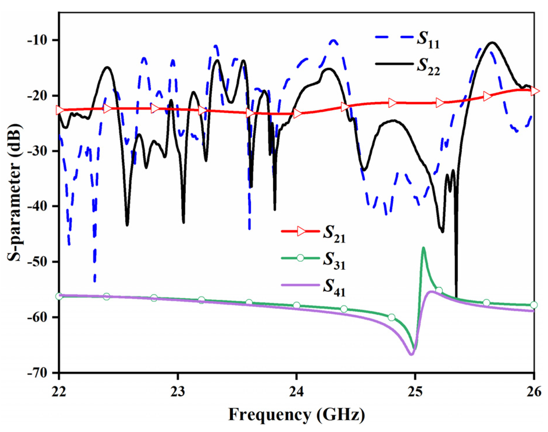
3.1. Reflection Coefficient and Isolation

Due to the commendable consistency in amplitude and phase of TEM mode waves propagating within PPWs, the two ports with orthogonal feeding directions exhibit high isolation, and the cross-polarization is minimal. Co-polarization isolation between port 1 and port 2 is below −21 dB, while cross-polarization isolation between port 1 (port 2) and port 3 (port 4) is below −55 dB, as depicted in Figure 12. The bandwidth encompasses the entire range of 23 GHz to 25 GHz.

3.2. Antenna Gain

All simulations were performed in the CST microwave studio. Figure 13 exhibits the agreement between simulated and measured antenna gains across various frequencies for beam 1, beam 2, beam 3, and beam 4. The simulated antenna gain at 24 GHz is 32.19–32.6 dBi with a radiation efficiency of 78.9%, while the measured antenna gains range from 31.09–31.89 dBi. The slight differences can be attributed to measurement errors and manufacturing tolerances. The CTS array demonstrates the capability for frequency scanning attributed to the broadband characteristics of the CTS element and the feed structure. As the CTS array is fed in series, variations in frequency induce changes in the phase difference among its elements, consequently altering the beam direction of the array antenna. At 24 GHz, the beams deflect ±15° ± 0.2° as intended, and the measured gain remains stable around 31 dB from 23 GHz to 25 GHz, with sidelobe levels below −17.6 dB.

3.3. Comparison with Other Works

Table 1 compares the proposed CTS antenna with other works, highlighting its advantages of high gain (>31 dBi), low sidelobe (<−17.6 dB), dual-polarization, and four beams. In contrast to the LSG represented as a horn combined with a reflector as outlined in [32,33,34,35], the LSG configured as a power divider offers the convenience of feeding the radiation element array responsible for generating four tilted beams, while concurrently exhibiting a lower reflection coefficient. The solutions proposed in [33] are fabricated employing substrate-integrated waveguide technology, characterized by its small volume, yet concomitantly incurring notable losses. The LSG, configured as a multi-horn-fed reflector, enables a parallel-fed radiation element array to generate multiple beams within a singular plane. However, it lacks the capability to generate tilted beams positioned in two orthogonal planes, rendering it unsuitable for deployment in WPR applications. Although authors of [36] used a series feeding network, the scanning beam was limited to one plane and could not generate four rotationally symmetric beams. Unlike the mentioned works [34,37] focusing on large-angle beam scanning, our antenna maintains a compact profile while offering dual-polarization and excellent performance. This millimeter-wave CTS antenna presents a promising alternative to wind profile radar for detecting wind turbulence signals at heights below 300 m.

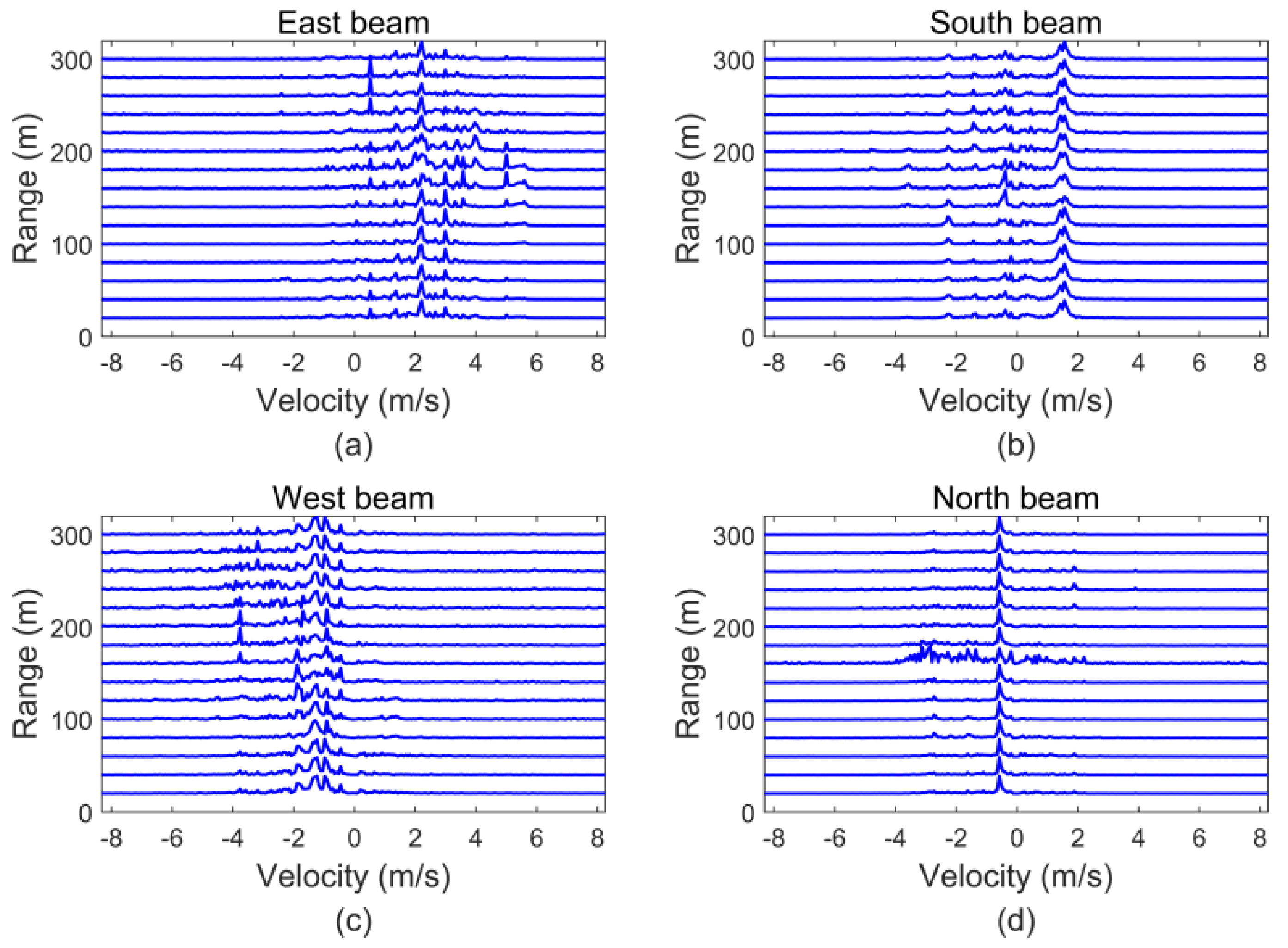
3.4. Experiments on the Radar System

The proposed CTS antenna was integrated into a single-antenna low-altitude wind profile radar to validate its performance and advantages. This single-antenna radar offers the benefits of lower cost and increased portability compared to multiantenna systems, expanding its applicability. The principle of wind profile radar in measuring wind speed is that strong backscattering occurs when the size of atmospheric turbulence is comparable to half of the electromagnetic wavelength. The wind profile radar detects the electromagnetic wave signal scattered by atmospheric turbulence, and according to the Doppler frequency shift and echo time difference, the velocity and distance of turbulence relative to the radar can be calculated. However, the turbulence echo signal is very weak and accompanied by random fluctuations, so the wind profile radar antenna needs to have high gain. At the same time, ground clutter produces strong interference to the radar, and the suppression of antenna sidelobe is significant. As shown in Figure 14, the radar system mainly comprises five parts: transmitter and receiver, CTS array antenna, radome, and baseband with data interaction function. The four ports of the CTS array antenna are connected to the transmitter and receiver channels through four circulators, enabling four-beam functionality and improved isolation. Above the CTS array antenna is the radome. The radome protects the antenna, and the significant slope of the conical structure surface makes it difficult for rain and other sundries to attach to the radome to ensure that the radar can work normally in adverse weather.
The wind profile radar was placed on the bank of the Yangtze River in Shanghai for outdoor testing. The CTS array antenna was installed inside the wind profile radar. As shown in Figure 15, metal baffles are installed around the radar to shield the interference from surrounding ground clutter. The radar data were recorded using a computer, which was 15 m away, to avoid the interference of electronic equipment on the radar. The conical radome was not installed in this outdoor test to avoid the impact of other factors on the antenna. The weather was clear that day, and only a breeze blew along the river. The radar could detect the noticeable Doppler frequency shift of the scattering signal generated by the relative movement of atmospheric turbulence.
The CTS array antenna, featuring four 15° inclined beams, captured scattering signals at corresponding angles. Utilizing the Doppler frequency shift of these signals enabled the calculation of four velocity vectors relative to the radar coordinate system, and the horizontal wind speed and direction could be calculated by combining the vectors. According to this principle, the wind profile radar can monitor the wind speed in the horizontal plane at multiple heights in real time. Figure 16 shows improved wind field measurement (at 300 m) with this antenna in the radar architecture. It can be seen that although many clutter signals are generated due to the surrounding complex electromagnetic environment interference, the atmospheric turbulence echo signal is still clearly visible. The high-gain and low-sidelobe characteristics of the CTS array antenna improve the quality of the echo signal detected using the radar. This brings considerable convenience to the subsequent radar signal processing to reduce clutter interference and improve the accuracy of wind speed calculation.

4. Conclusions

This paper presented a 24 GHz CTS array antenna with a high-gain, low-sidelobe, reconfigurable, dual-polarized, and low-profile design. The CTS array configuration was realized by integrating CTS radiation stubs, four 1-to-14 LSG series-fed feed structures, and coaxial-to-waveguide transition structures. This design achieved a four-beam fast switching scanning configuration with ±15° deflection, tailored for the specific requirements of millimeter-wave wind profile radar applications. The antenna’s performance was validated through simulation, fabrication, and measurement, showing sidelobe levels below −17.6 dB and gains over 31.09 dBi at 23–25 GHz, which agreed well with the simulated results. With its reconfigurable capability, dual-polarization, high gain, low sidelobe, and compact profile, this antenna can be applied for detecting weak wind turbulence signals within a 300 m range.

Author Contributions

Conceptualization, Y.L. and W.Z.; validation, L.Y. and W.Z.; writing—original draft preparation, L.Y.; writing—review and editing, K.Z. and Y.L.; funding acquisition, G.Y. and Y.L. All authors have read and agreed to the published version of the manuscript.

Funding

This work is supported by Suzhou Dufeng Technology Co., Ltd. under Grant No. D.71-0107-19-115.

Data Availability Statement

The data presented in this study are private, from the School of Communication and Information Engineering, Shanghai University, and Suzhou Dufeng Technology Co., Ltd.

Conflicts of Interest

Author Wenbin Zou was employed by the company R&D Department of CGN Digital Technology Co., Ltd. Author Guangli Yang was employed by the company Suzhou Dufeng Technology Co., Ltd. The remaining authors declare that the research was conducted in the absence of any commercial or financial relationships that could be construed as a potential conflict of interest.

References

  1. Algarni, A.S.; Suryanarayanan, S.; Siegel, H.J.; Maciejewski, A.A. Combined Impact of Demand Response Aggregators and Carbon Taxation on Emissions Reduction in Electric Power Systems. IEEE Trans. Smart Grid 2021, 12, 1825–1827. [Google Scholar] [CrossRef]
  2. Brigada, D.J.; Ryvkina, J. Radar-Optimized Wind Turbine Siting. IEEE Trans. Sustain. Energy 2022, 13, 403–413. [Google Scholar] [CrossRef]
  3. Dolatabadi, A.; Mohammadi-Ivatloo, B.; Abapour, M.; Tohidi, S. Optimal stochastic design of wind integrated energy hub. IEEE Trans. Ind. Inf. 2017, 13, 2379–2388. [Google Scholar] [CrossRef]
  4. Dolatabadi, A.; Abdeltawab, H.; Mohamed, Y.A.-R.I. Deep Spatial-Temporal 2-D CNN-BLSTM Model for Ultrashort-Term LiDAR-Assisted Wind Turbine’s Power and Fatigue Load Forecasting. IEEE Trans. Ind. Inform. 2022, 18, 2342–2353. [Google Scholar] [CrossRef]
  5. Spinato, F.; Tavner, P.J.; van Bussel, G.J.W.; Koutoulakos, E. Reliability of wind turbine subassemblies. IET Renew. Power Gener. 2009, 3, 387–401. [Google Scholar] [CrossRef]
  6. Choi, D.; Shin, W.; Ko, K.; Rhee, W. Static and Dynamic Yaw Misalignments of Wind Turbines and Machine Learning Based Correction Methods Using LiDAR Data. IEEE Trans. Sustain. Energy 2019, 10, 971–982. [Google Scholar] [CrossRef]
  7. Rundong, Q.; Changcheng, H.; Wenbin, T. Wind Measurement with a Wind Profiling Radar. Syst. Eng. Electron. 1991, 2, 81–88. [Google Scholar]
  8. Sterlyadkin, V.V.; Gorelik, A.G.; Kulikovskii, K.V.; Kalmykov, V.M.; Ermilov, D.V.; Khomyakov, A.V. Field measurements of the wind profile using millimeter Doppler radar. In Proceedings of the 2017 Progress in Electromagnetics Research Symposium—Spring (PIERS), St. Petersburg, Russia, 22–25 May 2017; pp. 897–901. [Google Scholar]
  9. Zhou, W.; Wu, L.; Wang, H.; Li, F.; Yang, X.; Li, R. Improvement of L-band Wind Profile Radar System. In Proceedings of the International Conference on Meteorology Observations (ICMO), Chengdu, China, 28–31 December 2019. [Google Scholar]
  10. Sinha, S.; Regeena, M.L.; Sarma, C.T.V.; Hashiguchi, H.; Tuckley, K.R. Doppler Profile Tracing Using MPCF on MU Radar and Sodar: Performance Analysis. IEEE Geosci. Remote Sens. Lett. 2018, 15, 508–511. [Google Scholar] [CrossRef]
  11. Röttger, J.; Ierkic, H.M. Postset beam steering and interferometer applications of VHF radars to study winds, waves, and turbulence in the lower and middle atmosphere. Radio Sci. 1985, 20, 1461–1480. [Google Scholar] [CrossRef]
  12. Doviak, R.J.; Zhang, G.; Cohn, S.A.; Brown, W.O.J. Comparison of spaced-antenna baseline wind estimators: Theoretical and simulated results. Radio Sci. 2004, 39, RS100. [Google Scholar] [CrossRef]
  13. Venkatesh, V.; Orzel, K.; Frasier, S. Spaced-Antenna Aperture Synthesis Using an X-Band Active Phased-Array. IEEE Geosci. Remote Sens. Lett. 2021, 18, 1194–1198. [Google Scholar] [CrossRef]
  14. Domps, B.; Marmain, J.; Guérin, C.A. Rapid Scale Wind Profiling with Autoregressive Modeling and L-Band Doppler Radar. IEEE Trans. Geosci. Remote Sens. 2022, 60, 4110010. [Google Scholar] [CrossRef]
  15. Nishizawa, K.; Miyashita, H.; Wakayama, T.; Matsuda, T.; Hashiguchi, H.; Fukao, S. A 1.3 GHz active phased array antenna for wind profiling boundary layer radar. In Proceedings of the IEEE International Symposium on Phased Array Systems and Technology, Boston, MA, USA, 14–17 October 2003; pp. 142–145. [Google Scholar]
  16. Krasnov, O.A.; Yarovoy, A.G. Radar micro-Doppler of wind turbines: Simulation and analysis using slowly rotating linear wired constructions. In Proceedings of the 2014 11th European Radar Conference, Rome, Italy, 8–10 October 2014; pp. 73–76. [Google Scholar]
  17. Lindseth, B.; Brown, W.O.; Jordan, J.; Law, D.; Hock, T.; Cohn, S.A.; Popovic, Z. A New Portable 449-MHz Spaced Antenna Wind Profiler Radar. IEEE Trans. Geosci. Remote Sens. 2012, 50, 3544–3553. [Google Scholar] [CrossRef]
  18. Matos, S.A.; Costa, J.R.; Fernandes, C.A.; Alves, A.A.; Fonseca, N.J.G. Reducing Beam Aberrations of Mechanical Scanning Transmit-array Antennas. In Proceedings of the 2020 IEEE International Symposium on Antennas and Propagation and North American Radio Science Meeting, Montreal, QC, Canada, 5–10 July 2020; pp. 1785–1786. [Google Scholar]
  19. Samson, T.K.; Kottayil, A.; Manoj, M.G.; Binoy, B.B.; Rakesh, V.; Rebello, R.; Vasudevan, K.; Mohanan, P.; Santosh, K.R.; Mohankumar, K. Technical Aspects of 205 MHz VHF Mini Wind Profiler Radar for Tropospheric Probing. IEEE Geosci. Remote Sens. Lett. 2016, 13, 1027–1031. [Google Scholar] [CrossRef]
  20. Samson, T.K.; Babu, B.; Anandan, V.K.; Rakesh, V.; Rebello, R.; Mohanakumar, K.; Mohanan, P. Phased array of 619-element Yagi-Uda antenna for Wind Profiler Radar at Cochin University of Science and Technology. In Proceedings of the 2019 URSI Asia-Pacific Radio Science Conference (AP-RASC), New Delhi, India, 9–15 March 2019; pp. 1–4. [Google Scholar]
  21. Srinivasulu, P.; Yasodha, P.; Kamaraj, P.; Rao, T.N.; Jayaraman, A.; Reddy, S.N.; Satyanarayana, S. 1280-MHz Active Array Radar Wind Profiler for Lower Atmosphere: System Description and Data Validation. J. Atmos. Ocean. Technol. 2012, 29, 1455–1470. [Google Scholar] [CrossRef]
  22. Hong, W.; Jiang, Z.H.; Yu, C.; Hou, D.; Wang, H.; Guo, C.; Hu, Y.; Kuai, L.; Yu, Y.; Jiang, Z.; et al. The Role of Millimeter-Wave Technologies in 5G/6G Wireless Communications. IEEE J. Microw. 2021, 1, 101–122. [Google Scholar] [CrossRef]
  23. Ku, B.H.; Schmalenberg, P.; Inac, O.; Gurbuz, O.D.; Lee, J.S.; Shiozaki, K.; Rebeiz, G.M. A 77–81-GHz 16-Element Phased-Array Receiver With ±50° Beam Scanning for Advanced Automotive Radars. IEEE Trans. Microw. Theory Technol. 2014, 62, 2823–2832. [Google Scholar] [CrossRef]
  24. Wu, Y.W.; Miao, Z.W.; Luo, G.Q.; Hao, Z.C. Planar Millimeter-Wave Shared-Aperture Self-Duplexing Antenna with Small Frequency Ratio and High Isolation. IEEE Trans. Antennas Propag. 2021, 69, 8979–8984. [Google Scholar] [CrossRef]
  25. Zhu, G.; Ding, Y.; Yang, G. Design of Shaped Dielectric Lens Antenna for Millimeter Wave Wind Profile Radar. In Proceedings of the 2021 International Conference on Microwave and Millimeter Wave Technology (ICMMT), Nanjing, China, 23–26 May 2021; pp. 1–3. [Google Scholar]
  26. Manzillo, F.F.; Ettorre, M.; Casaletti, M.; Capet, N.; Sauleau, R. Active impedance of infinite parallel-fed continuous transverse stub arrays. IEEE Trans. Antennas Propag. 2015, 63, 3291–3297. [Google Scholar] [CrossRef]
  27. Ettorre, M.; Manzillo, F.F.; Casaletti, M.; Sauleau, R.; Le Coq, L.; Capet, N. Continuous Transverse Stub Array for Ka-Band Applications. IEEE Trans. Antennas Propag. 2015, 63, 4792–4800. [Google Scholar] [CrossRef]
  28. Milroy, W.W. The continuous transverse stub (CTS) array: Basic theory, experiment, and application. Proc. Antenna Appl. Symp. 1991, 2, 253–283. [Google Scholar]
  29. Milroy, W.W. Planar Antenna Radiating Structure Having Quasi-Scan, Frequency-Independent Driving-Point Impedance. U.S. Patent 5 995 055A, 1999. [Google Scholar]
  30. Lu, X.; Gu, S.; Wang, X.; Liu, H.; Lu, W. Beam-Scanning Continuous Transverse Stub Antenna Fed by a Ridged Waveguide Slot Array. IEEE Antennas Wirel. Propag. Lett. 2017, 16, 1675–1678. [Google Scholar] [CrossRef]
  31. Samardzija, M.; Kai, T.; Hirokawa, J.; Ando, M. Single-layer waveguide feed for uniform plane TEM-wave in oversized rectangular waveguide with hard-surface sidewalls. IEEE Trans. Antennas Propag. 2006, 54, 2813–2819. [Google Scholar] [CrossRef]
  32. Potelon, T.; Ettorre, M.; Le Coq, L.; Bateman, T.; Francey, J.; Lelaidier, D.; Seguenot, E.; Devillers, F.; Sauleau, R. A Low-Profile Broadband 32-Slot Continuous Transverse Stub Array for Backhaul Applications in E-Band. IEEE Trans. Antennas Propag. 2017, 65, 6307–6316. [Google Scholar] [CrossRef]
  33. Mastro, M.D.; Mahmoud, A.; Potelon, T.; Sauleau, R.; Quagliaro, G.; Grbic, A.; Ettorre, M. Ultra-Low-Profile Continuous Transverse Stub Array for SatCom Applications. IEEE Trans. Antennas Propag. 2022, 70, 4459–4471. [Google Scholar] [CrossRef]
  34. Potelon, T.; Ettorre, M.; Coq, L.L.; Bateman, T.; Francey, J.; Sauleau, R. Reconfigurable CTS Antenna Fully Integrated in PCB Technology for 5G Backhaul Applications. IEEE Trans. Antennas Propag. 2019, 67, 3609–3618. [Google Scholar] [CrossRef]
  35. Potelon, T.; Ettorre, M.; Sauleau, R. Long Slot Array Fed by a Nonuniform Corporate Feed Network in PPW Technology. IEEE Trans. Antennas Propag. 2019, 67, 5436–5445. [Google Scholar] [CrossRef]
  36. Sun, S.; Zhao, Y.; Zheng, Y.; Zhou, N.; Ban, Y. A continuous transverse stub array with parabolic reflector for Ka-band multibeam application. AEU Int. J. Electron. Commun. 2023, 170, 154818. [Google Scholar] [CrossRef]
  37. You, Y.; Lu, Y.; Wang, Y.; Xu, J.; Huang, J.; Hong, W. Enhanced Pencil-Beam Scanning CTS Leaky-Wave Antenna Based on Meander Delay Line. IEEE Antennas Wirel. Propag. Lett. 2021, 20, 1760–1764. [Google Scholar] [CrossRef]
Figure 1. Installation position of wind profile radar.
Electronics 13 00238 g001
Figure 2. Configuration of the CTS array. (a) Perspective view; (b) side view; (c) partial view of the feed structure.
Electronics 13 00238 g002
Figure 3. (a) Side view of CTS radiation element; (b) 3D view of radiation stubs.
Electronics 13 00238 g003
Figure 4. Reflection coefficient of the PPW feeding port.
Electronics 13 00238 g004
Figure 5. The 24 GHz phase difference between CTS element characteristics and main beam pointing with different periods p.
Electronics 13 00238 g005
Figure 6. Partial perspective view of the 1-to-14 LSG feed structure.
Electronics 13 00238 g006
Figure 7. Partial top view of the 1-to-14 LSG feed structure.
Electronics 13 00238 g007
Figure 8. LSG (a) phase and (b) transmission coefficient characteristics to different combinations of metallic post radius R3 and position d4 at 24 GHz.
Electronics 13 00238 g008
Figure 9. (a) Electric field of the LSG feed structure at 24 GHz; (b) reflection coefficient of the LSG feed structure.
Electronics 13 00238 g009
Figure 10. (a) Cross-section of transition parts; (b) transmission and reflection coefficient characteristics to different step heights D of waveguide transition structure at 24 GHz.
Electronics 13 00238 g010
Figure 11. (a) Assembled antenna and its components; (b) measurement environment of the antenna.
Electronics 13 00238 g011
Figure 12. Measured S-parameters of the whole CTS antenna.
Electronics 13 00238 g012
Figure 13. Simulated and measured radiation patterns of four reconfigurable beams at three frequency points: 23, 24, and 25 GHz. (a) Beam 1. (b) Beam 2. (c) Beam 3. (d) Beam 4.
Electronics 13 00238 g013
Figure 14. Section view of low-altitude wind measurement radar.
Electronics 13 00238 g014
Figure 15. The testing site environment.
Electronics 13 00238 g015
Figure 16. Actual test results on radar. (a) East beam. (b) South beam. (c) West beam. (d) North beam.
Electronics 13 00238 g016
Table 1. Performance comparison of CTS arrays.
RefBW (GHz)Gain (dBi)SLLs (dB)PolarizationScanning Range
[32]71~86>29.3<−13.3SingleN/A
[33]19~31>19.7<−15Dual±22.5°
[34]71~86>17.5N/ASingle−14~14°
[35]71~86>23.9<−18SingleN/A
[36]33~37>20.9<−10.6Single±38°
[37]26~34>22.5<−13.5Single−68~42°
This
work
23~25>31.0<−17.6Dual±15°
Disclaimer/Publisher’s Note: The statements, opinions and data contained in all publications are solely those of the individual author(s) and contributor(s) and not of MDPI and/or the editor(s). MDPI and/or the editor(s) disclaim responsibility for any injury to people or property resulting from any ideas, methods, instructions or products referred to in the content.

