Article

Influence of the Cast Iron Frame on the Distribution of the Magnetic Field in the Stator Yoke and Additional Power Losses in the Induction Motor

Institute of Mechatronics and Information Systems, Lodz University of Technology, Stefanowskiego 18/22, 90-924 Lodz, Poland
*
Author to whom correspondence should be addressed.
Electronics 2024, 13(1), 119; https://doi.org/10.3390/electronics13010119
Submission received: 18 November 2023 / Revised: 20 December 2023 / Accepted: 25 December 2023 / Published: 27 December 2023

Abstract

:
Induction motors are a significant consumer of electricity. Therefore, their energy efficiency level plays a vital role in the world’s energy balance. The world’s markets strive to produce motors of efficiency class IE3 or IE4 while maximizing the use of wire and magnetic materials. However, high induction values in the motor core can also lead to significant losses in construction materials, especially in the magnetic motor housing. This article aimed to show how it is possible to determine the distribution of the magnetic field and additional losses in the yoke and the cast-iron motor frame using field-circuit methods to model the motor and to refine the analytical method for calculating these losses at the motor design stage.

1. Introduction

Induction motors, particularly squirrel cage motors, are widely used in many industries. The serial low-voltage, low- and medium-power motors currently manufactured and available on the market should meet the European Commission Regulation 2019/1781 requirements and related standards regarding the minimum efficiency of electric motors placed on the EU market. The problem arises in the case of unit production of low- and high-voltage motors, especially high-power motors (with shaft heights of 315 mm and above), used in specialized drives in heavy industry. These motors often have lower efficiency than those of the IE1 class. This applies in particular to LV motors, which, due to size limitations and resulting from the requirements of the drive system, have extensive use of the magnetic circuit, especially the stator yoke. In these motors, the induction in the yoke is often close to 1.8 T [1,2,3,4]. As a result, the magnetic field penetrates the cast-iron housing, often causing significant power losses and reducing the machine’s efficiency. This problem is much smaller in the case of HV motors. Figure 1 shows an exemplary division of LV and HV induction motors with shaft axis heights of 315 mm or more, depending on their efficiency classes.
In HV motors, the use of the magnetic circuit is generally more minor. As a result, as shown in Figure 1, almost 75% of motors achieve efficiency corresponding to the requirements of the IE3 or IE4 efficiency classes. New requirements for the minimum efficiency level of asynchronous motors were introduced to the European Union market by EU Commission Regulation 2019/1781 as amended 2021/341 [5]. The basic quantity determining the expected savings from using an energy-saving motor is its efficiency, which is related to the efficiency class. In the European Union, electric motors are divided in terms of efficiency using the IE (international efficiency) classification according to the EN 60034-30-1:2014 standard. The motor is assigned to a given efficiency class by comparing the machine efficiency determined according to an established measurement method (according to the EN 60034-2-1:2007 standard) with the minimum efficiency requirements for a given IE class [6,7,8,9,10,11,12,13].
A significant reduction in the efficiency of motors with heavy use of the magnetic circuit is often caused by the magnetic field’s penetration into the motor’s structural parts (shaft and magnetic hull) and generation of additional power losses in them. Papers [14,15,16] provide methods for calculating the magnetic induction in the yoke of an induction motor, considering the magnetic field’s penetration into the motor body and shaft. At the same time, in the available literature, there are no methods for calculating losses in the magnetic motor housing, even if they raise associated issues [17,18,19,20,21,22,23,24,25]. More attention was paid to analyzing phenomena related to the stator end connections. The authors of [26] present an analysis of phenomena in the case of a high-power nonskewed cage induction motor using finite element three-dimensional method (FEM 3D) analysis. Similar results were presented in papers [27,28], but more attention was paid to losses in the clamping parts of the machine. However, 3D models are very time-consuming, so usually simplified two-dimensional (2D) models were used [29]. The analytical methods provided in [14,15] allowed only calculations of induction in the motor yoke, taking into account the penetration of part of the yoke flux into the magnetic housing. These relationships have been used after being verified in the article using FEM simulations. The authors’ contribution is the development of a new formula that allows the analytical determination of losses in a magnetic conductive casing, taking into account the non-linearity of the casing material. These relationships have been developed using FEM models for cast iron, most often used in constructing magnetic housing. They allow us to determine the losses in the housing based only on the magnetic field strength on the inner surface of the housing, which is determined based on the previously mentioned field values in the motor yoke. The results of calculations of motor operating parameters, considering the magnetic field penetration into the frame and the resulting power losses, were compared with the measurement results.
Section 2 presents the research objects. Section 3 presents the application of the analytical method for calculating losses in a massive casing and the correction of its results using numerical analysis, allowing the changes in the material’s permeability to be considered. Section 3 also presents analytical relationships enabling the calculation of losses in the casing, taking into account the introduced corrections. Section 4 presents the calculation results, a comparison of analytical calculations with numerical simulation, and a comparison with available measurement results.

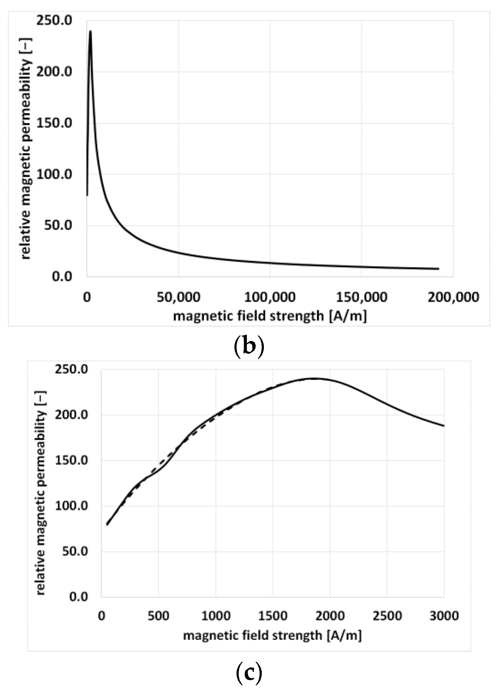
2. Objects for Investigation

Two high-power induction motors were the subject of the investigation: a low-voltage motor A with a shaft height of 315 mm and a high-voltage motor B with a shaft height of 710 mm. The basic rated parameters and main dimensions of these motors are listed in Table 1.
The cores of the motors are made of M400-50A [30] electrical sheet metal with a thickness of 0.5 mm. Both motors have a magnetic housing made of gray cast iron EN-GJL-250 [31,32,33] with a pearlitic matrix with particles of flake graphite and with the following material properties: density of 7.2 g/cm3, resistivity of 0.73 Ω·mm2/m, magnetic permeability of 220~330 μH/m, and hysteresis losses of 2500~3000 J/m3 at magnetic induction B = 1T.
Figure 2a shows the magnetization characteristics, while Figure 2b shows the relative magnetic permeability as a function of the magnetic field strength of the gray cast iron.

3. Field-Circuit Analysis

For field-circuit analysis, we assume that the induction has only a tangential component at the boundary between the yoke and the casing shown in Figure 3. Hence, the continuity condition of the tangential components of the magnetic field strength vector is valid at the border. For high-power machines, the external diameter of the stator is large enough that the housing can be treated as a conductive half-space. For most machines, the casing thickness is much greater than the equivalent penetration depth δ (defined in Equation (1)).
The phenomena can be described for the linear environment using the known relationships for the conductive half-space [34,35].
2 H y ¯ x 2 = α 2 H y ¯   α = j ω μ γ = 1 + j k   k = ω μ γ 2 = 1 δ
where Hy is the complex value of the tangential component of magnetic field strength, j is an imaginary unit, ω is the angular velocity, µ is magnetic permeability, γ is the electric conductivity of the housing material, k is the attenuation constant, and δ is the equivalent depth of field penetration (also called skin depth).
Hence,
H y ¯ = H s y ¯   e α x
where the subscript s means that it is the value on the surface of the half-space. The electric field strength can be determined as follows:
H y ¯ x = γ E z ¯
Hence,
E z ¯ = 1 γ H y ¯ x = α γ H s y ¯ e α x
Eddy current losses are represented by Equation (5) and hysteresis losses, assuming a quadratic dependence of losses on the induction, by Equation (6).
P e = l F e 2 π r f π f μ γ H x = 0 2 2 = l F e 2 π r f 1 δ 1 γ H x = 0 2 2
H x = H x = 0 e x δ B x = μ H x = μ H x = 0 e x δ = B x = 0 e x δ p h = c h B 2 P h l F e 2 π r f 0 r z c h B x 2 d x l F e 2 π r f 0 c h B x 2 d x P h = l F e 2 π r f 0 c h B x = 0 e x δ 2 d x = l F e 2 π r f c h δ 2 B x = 0 2
where rf is the inside radius of the housing.
Additionally, the magnetic flux closing through the housing, described by Equation (7), should be considered in the calculations.
H _ x = H _ x = 0 e k x k = 1 δ = π f μ γ Ψ _ = l F e 0 r z B _ x d x l F e 0 B _ x d x Ψ _ = l F e 0 μ k H _ x = 0   e 1 + j k x d x = l F e μ k H _ x = 0 1 1 + j k Ψ _ = l F e μ k H _ x = 0 δ 2
where Ψ is the complex value of the magnetic flux penetrating the housing, while lFe is the length of the part of the housing directly in contact with the stator yoke.
The linear model (assuming a constant value of permeability along the thickness of the casing) was validated for an exemplary low-power induction motor, which additionally allowed us to examine the effect of curvature on the results. For this purpose, the results of analytical calculations were compared with a numerical simulation carried out in the Opera package using a steady-state module (Opera-2d/AC) [36] to solve eddy current models where all electromagnetic quantities vary sinusoidally in time. The housing parameters were adopted for high-power motors (hence a certain dimension disproportion in Figure 4).
The solution was determined for the linear variant (relative permeability of the frame equal to 200) and a frequency of 50 Hz.
Figure 5 shows the distribution of the magnetic field strength along the frame thickness x obtained from the FEM model and the approximation of this distribution using an exponential function. Obtaining a good-quality waveform requires, of course, adequate discretization using triangular elements. The applied division significantly exceeds the most frequently suggested division into at least three elements at a given penetration depth. The equivalent penetration depth δ was determined from Formula (1)—0.0042999, with an error about the simulation of 0.11%. The determined eddy current losses were as follows: from the 2D model—0.0396 W, and from the formula for an amplitude H on the surface equal to 74.95141 A/m—0.0375 W; the difference was 5.42%. The hysteresis losses were as follows: from the 2D model—0.009688 W, and from the formula for an amplitude B on the surface 0.0192 T—0.00937 W; the difference was 3.3%. The flux penetrating the housing (maximum value) was as follows: from the 2D model—5.76398E-06 Wb, and from the formula—5.85 × 10⁻⁶ Wb; the difference was −1.48%. As can be seen, the mapping is very accurate for the linear variant. Differences result from the curvature of the housing and FEM errors (the size of the dividing element in the radial direction is 0.5 mm for a penetration depth of 4.3 mm).
The frame made of cast iron is a non-linear material (Figure 1 and Figure 2). The change in permeability, along with the change in the magnetic field strength inside the frame, causes a change in the field distribution and thus affects the total eddy current and hysteresis losses compared to the linear case. The phenomena depend on the level of magnetic field strength and, therefore, on the magnetic field strength, at an edge of the yoke because it determines the boundary value on the surface of the housing. The problem of the influence of non-linearity on phenomena in a ferromagnetic conductive field was noticed a long time ago. Among other things, Turowski’s works [35,36] proposed constant correction factors for losses for non-linear materials. However, with the change in saturation, these values have significant variability. Therefore, the authors determined the correction factors for the selected type of cast iron using FEM simulation. Of course, these relationships are only valid if the casing thickness is much greater than the equivalent penetration depth, which is the case for most structures. Of course, these steps would have to be repeated for a different casing material.
Figure 6, Figure 7 and Figure 8 show the eddy current losses improvement coefficient (ELIC) factor for correcting eddy current losses from linear to non-linear cases. It was determined as a function of the magnetic induction amplitude on the housing surface. Two types of approximation were proposed: quadratic polynomial and linear approximation for selected induction ranges. As you can see, non-linearity causes a significant increase in losses of up to 40% of the losses calculated for the linear variant.
Figure 9 and Figure 10 show the hysteresis losses improvement coefficient from linear to non-linear cases (HLIC) factor for correcting hysteresis losses in the frame. It was determined as a function of the magnetic induction amplitude and magnetic field strength on the housing surface. Two types of approximation were proposed: linear for induction and logarithmic for magnetic field strength. Similarly, as with eddy current losses, non-linearity causes a significant increase in hysteresis losses of up to 85% of the losses calculated for the linear variant.
In the case of the flux penetrating the housing, it does not require correction to the induction in a yoke not exceeding 1.5 T, while for higher values, the calculated magnetic flux should be increased by 10%.
Figure 11 and Figure 12 present the simulation results for motor A using a periodic steady-state Opera package module, which uses a complex approximation method that postulates that the solution obtained by the electromagnetic field equation undergoes sinusoidal variation over time.
It should be emphasized that in periodic analysis, the permeability of a ferromagnetic material is determined based on the maximum value of magnetic induction, which is, of course, the reason for some simplifications compared to time-stepping transient analysis.
This is why the maximum value of induction in the frame is constant along the circumference of the machine for a constant distance from the frame wall.
Similar distributions are shown in Figure 13 and Figure 14 for motor B.
Comparing the distributions for both machines, we can see how significantly the saturation of the motor, and thus the value of induction in the yoke, affects the phenomena in the housing.

4. Analytical Calculation

Analytical calculations of magnetic induction in the magnetic frame of an induction motor are carried out based on the analysis of the magnetic field distribution in the motor. The decrease in the amplitude of the average magnetic induction in the stator yoke Δ B s y as a result of the magnetic flux penetration from the rotor yoke to the cast-iron body can be calculated from Formula (8) [15].
Δ B s y = 1.37 α   µ k d H s y ψ k h s y k F e
ψ k = k k 2 + ( µ k d γ k d υ ) 2   ;   α = k 2 + ψ k 2   ;    k = 2 p D s e ;
where υ = π f s D s e p —linear velocity of the field on the outer circumference of the yoke,
H s y —magnetic field strength in the stator yoke, determined based on the electrotechnical sheet magnetization characteristics for the average induction in the stator yoke B s y ,
µ k d —magnetic permeability of the frame approximated based on the characteristics presented in Figure 2; µ k d = (−0.0000419 Hsy2 + 0.1670644 Hsy + 72.5397973) µ 0 applicable for Hsy < 2000 A/m; µ k d = (86,366 Hsy − 0.761) µ 0 for Hsy > = 2000 A/m,
µ 0 —the magnetic permeability of a vacuum ( µ 0 = 0.4 π 10 6 ),
γ k d —conductivity of the frame material (1.37 × 10⁶ S/m in case of investigated cast iron),
h s y —stator yoke height,
D s e —outer diameter of the stator core,
p—number of pole pairs,
k F e —fill factor of electrotechnical sheets ( k F e = 0.96),
fs—frequency of the motor’s rotating field.
Calculations are performed for the initial value of magnetic induction B s y 0 , determined without considering the magnetic flux penetration into the frame. Then, a new value of induction is selected from the relation:
B s y = B s y 0 Δ B s y
Calculations are repeated iteratively until the assumed accuracy is achieved (0.1%).
The correction factor 1.37 introduced in [15,16] in Formula (8) considers that the frame’s magnetic permeability is not constant but increases because the magnetic field strength decreases with the depth of magnetic flux penetration into the frame.
For the value of magnetic induction in the stator yoke determined in this way, it is possible to determine a new value of the magnetic field strength in the stator yoke, equal to the value of the magnetic field in the cast-iron frame, and to calculate the maximum value of magnetic induction in the frame from the relation:
B k d = µ k d H s y
The power losses occurring in the frame are the sum of hysteresis and eddy current losses. The phenomena can be described for a linear environment using the known relationships for a conductive half-space. Hysteresis losses in a cast-iron frame, assuming a quadratic dependence of losses on magnetic induction, can be calculated based on the following relationship:
P h = 0.5 π c h D s e L s δ B k d 2 δ = 1 π f s µ k d γ k d
where c h —hysteresis loss coefficient of gray cast iron (125,000–150,000) (W/m3),
δ —depth of penetration of the magnetic field into the cast iron frame.
Eddy current losses are calculated from the following dependence:
P w = π D s e L s H s y 2 2 δ γ k d
Housing losses calculated according to the formulas for half-spaces (11) and (12) should be multiplied by the correction factors ELIC for eddy current losses and HLIC for hysteresis losses, which are approximated for EN-GJL-250 gray cast iron by the following relationships:
ELIC = 0.5505 Bkd + 1.0 for Bkd < 0.8 T,
  ELIC = −0.233 Bkd + 1.614 for Bkd ≥ 0.8 T,
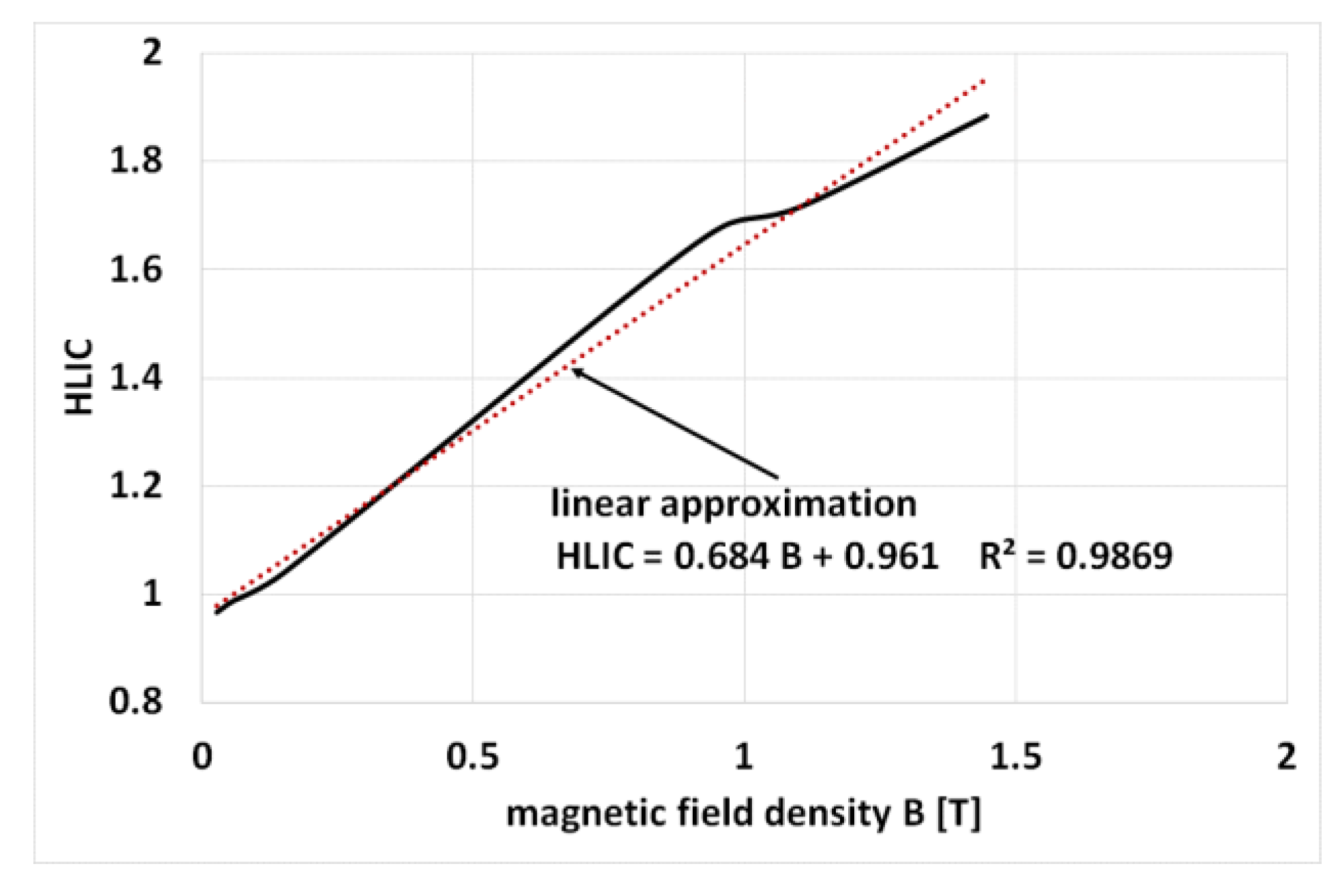
      HLIC = 0.684 Bkd + 0.961 for the entire Bkd range.
These coefficients, as already mentioned in Section 3, make it possible to consider the influence of the non-linearity of the casing material.

5. Calculation Results

The presented analytical methods for determining the induction and power losses in the frame were used to calculate the electromagnetic parameters and operating characteristics of induction motors using the proprietary improved STAT program [37].
Table 2 lists the results of magnetic induction and losses calculations in the yoke and frame obtained by the analytical method and the field-circuit method calculations for motor A, while Table 3 is for motor B.
In [14], the effective height of the stator yoke is calculated from the approximate relationship:
h sy   =   h sy 0   +   0.64   δ   =   0.03673   +   0.00835   =   0.04508
Thus, it gives a value about 10% higher than that in Table 2.
As seen from Table 2, motor A extensively uses the magnetic circuit, especially the stator yoke, due to significant field penetration into the frame, and immense power losses are generated in it.
Table 3 shows that motor B makes very little use of the magnetic circuit. Hence, the losses in the housing are minimal and do not affect the motor’s operating characteristics.
Table 4 compares selected operational parameters of motor A, measured and calculated, while taking into account the penetration of the field into the cast-iron frame (magnetic frame) and while excluding this phenomenon (non-magnetic frame).
As can be seen from Table 4, in the considered motor A, the omission in the calculation of the power losses occurring in the frame, despite the very high induction value in the stator yoke, results in a significant overestimation of the efficiency value while reducing the value of the power factor. An analogous comparison of the results for motor B is given in Table 5.
As seen in Table 5, in the considered motor B, the field penetration into the frame is very small and practically does not affect the motor parameters. As one can see, in both cases, the measurement results match the simulation results well.

6. Conclusions

As presented in the article, losses in a massive ferromagnetic conductive housing can be a source of significant additional losses which are usually not included in the balance of motor losses, significantly affecting the motor’s efficiency and temperature increase.
This problem mainly concerns motors which make significant use of a magnetic circuit, which results in high induction values in the motor core, especially in the stator yoke. In addition to the losses in the part of the housing directly adjacent to the stator yoke, additional power losses can also occur in parts of the housing not adjacent to the stator core due to stray fluxes around the stator’s winding end connections. So far, this problem has been considered when analyzing losses in the front parts of the core and structural parts, such as the clamping plate and fingers in high-power turbogenerators and induction motors, as well as in the case of canned induction motors [38,39,40,41,42,43,44,45]. These phenomena will be the subject of further work for the authors.

Author Contributions

Conceptualization, K.K., M.D. and S.W.; methodology, K.K. and M.D.; software, K.K. and M.D.; validation, K.K., M.D. and S.W.; formal analysis, K.K.; investigation, K.K., M.D., S.W., R.L., J.P., P.S. and K.T.; data curation, K.K.; writing—original draft preparation, K.K., M.D., S.W., R.L., J.P., P.S. and K.T.; writing—review and editing, K.K., M.D., S.W., R.L., J.P., P.S. and K.T.; visualization, K.K.; supervision, K.K., M.D. and S.W.; project administration, K.K., M.D. and S.W. All authors have read and agreed to the published version of the manuscript.

Funding

This research received no external funding.

Data Availability Statement

The data presented in this study are available on request from the corresponding author. The data are not publicly available due to machine manufacturer access restrictions.

Conflicts of Interest

The authors declare no conflict of interest.

References

  1. Olivo, M.; Bortolozzi, M.; Tessarolo, A.; Luise, F. A New Method for the Accurate Prediction of On-Load Power Factor in Two-Pole Induction Motors Considering Shaft Eddy Currents. IEEE Trans. Energy Convers. 2020, 35, 1196–1207. [Google Scholar] [CrossRef]
  2. Reinlein, M.; Hubert, T.; Kremser, A.; Bauer, T. Magnetic flux distribution between rotor and shaft in two-pole induction machines with axial cooling vents. In Proceedings of the 2015 IEEE 5th International Conference on Power Engineering, Energy and Electrical Drives (POWERENG), Riga, Latvia, 11–13 May 2015; pp. 485–490. [Google Scholar]
  3. Kong, W.; Huang, J.; Qu, R.; Kang, M.; Yang, J. Nonsinusoidal Power Supply Analysis for Concentrated-Full-Pitch-Winding Multiphase Induction Motor. IEEE Trans. Ind. Electron. 2016, 63, 574–582. [Google Scholar] [CrossRef]
  4. Zhao, H.; Wang, B.; Piao, R.-h.; Lu, W. Time-stepping finite element analysis on iron loss distribution of cage induction motors. In Proceedings of the 2014 17th International Conference on Electrical Machines and Systems (ICEMS), Hangzhou, China, 22–25 October 2014; pp. 2043–2049. [Google Scholar] [CrossRef]
  5. Document 32021R0341. Available online: http://data.europa.eu/eli/reg/2021/341/oj (accessed on 17 November 2023).
  6. Cao, W. Comparison of IEEE 112 and New IEC Standard 60034-2-1. IEEE Trans. Energy Convers. 2009, 24, 802–808. [Google Scholar] [CrossRef]
  7. IEC/EN, 60034-30-1; Rotating Electrical Machines—Part 30-1: Efficiency Classes of Line Operated AC Motors (IE Code). ABB: Zürich, Switzerland, 2014.
  8. De Almeida, A.T.; Ferreira, F.J.T.E.T.E.; Fong, J.A.C. Standards for Efficiency of Electric Motors. IEEE Ind. Appl. Mag. 2011, 17, 12–19. [Google Scholar] [CrossRef]
  9. Alberti, L.; Troncon, D. Design of Electric Motors and Power Drive Systems According to Efficiency Standards. IEEE Trans. Ind. Electron. 2021, 68, 9287–9296. [Google Scholar] [CrossRef]
  10. Dems, M.; Komeza, K. Designing an Energy-Saving Induction Motor Operating in a Wide Frequency Range. IEEE Trans. Ind. Electron. 2022, 69, 4387–4397. [Google Scholar] [CrossRef]
  11. Al-Badri, M.; Pillay, P. Modified Efficiency Estimation Tool for Three-Phase Induction Motors. IEEE Trans. Energy Convers. 2023, 38, 771–779. [Google Scholar] [CrossRef]
  12. Stiscia, O.; Rubino, S.; Vaschetto, S.; Cavagnino, A.; Tenconi, A. Accurate Induction Machines Efficiency Mapping Computed by Standard Test Parameters. IEEE Trans. Ind. Appl. 2022, 58, 3522–3532. [Google Scholar] [CrossRef]
  13. Roshandel, E.; Mahmoudi, A.; Kahourzade, S.; Soong, W.L. Efficiency Maps of Electrical Machines: A Tutorial Review. IEEE Trans. Ind. Appl. 2023, 59, 1263–1272. [Google Scholar] [CrossRef]
  14. Dąbrowski, M. Projektowanie Maszyn Elektrycznych Prądu Przemiennego; Wydawnictwo Naukowo-Technicze: Warszawa, Poland, 1994; ISBN 83-2-041662-0. [Google Scholar]
  15. Śliwiński, T. Metody Obliczania Silników Indukcyjnych, t.1 Analiza; PWN: Warszawa, Poland, 2008; ISBN 978-8-30115-468-4. [Google Scholar]
  16. Frejtich, Z. Vypocet Magnetickeho Odlehceni Nasyceneho Indukcniho Motoru. Technika Electrickych Stroju 1972, 2, 90–98. [Google Scholar]
  17. Muller, G.; Vogt, K.; Ponick, B. Berechnung Elektrischer Maschinen; Technische Universitat Dresden, Elektrotechnisches Institut: Dresden, Germany, 2008. [Google Scholar] [CrossRef]
  18. Toliyat, H.A.; Kliman, G.B. Handbook of Electric Motors—Second EDITION, Revised and Expanded; CRC Press: Boca Raton, FL, USA, 2004; ISBN 978-1-42003-038-9. [Google Scholar]
  19. Pan, B.; Tao, D.; Ge, B.; Wang, L.; Hou, P. Analysis of Eddy Current Loss of 120-kW High-Speed Permanent Magnet Synchronous Motor. Machines 2022, 10, 346. [Google Scholar] [CrossRef]
  20. Yamazaki, K.; Fukushima, W. Loss Analysis of Induction Motors by Considering Shrink Fitting of Stator Housings. IEEE Trans. Magn. 2015, 51, 1–4. [Google Scholar] [CrossRef]
  21. Sundaria, R.; Lehikoinen, A.; Arkkio, A.; Belahcen, A. Effects of Manufacturing Processes on Core Losses of Electrical Machines. IEEE Trans. Energy Convers. 2021, 36, 197–206. [Google Scholar] [CrossRef]
  22. Stermecki, A.; Biro, O.; Bakhsh, I.; Rainer, S.; Ofner, G.; Ingruber, R. 3-D Finite Element Analysis of Additional Eddy Current Losses in Induction Motors. IEEE Trans. Magn. 2012, 48, 959–962. [Google Scholar] [CrossRef]
  23. Liang, Y.; Bian, X.; Yu, H.; Li, C. Finite-Element Evaluation and Eddy-Current Loss Decrease in Stator End Metallic Parts of a Large Double-Canned Induction Motor. IEEE Trans. Ind. Electron. 2015, 62, 6779–6785. [Google Scholar] [CrossRef]
  24. Bompou, E.; Mijatovic, N.; Træholt, C.; Willén, D.W.A.; Thidemann, C. Loss in Steel Armour Wires for Submarine Power Cables. In Proceedings of the 2018 IEEE Power & Energy Society General Meeting (PESGM), Portland, OR, USA, 5–10 August 2018; pp. 1–5. [Google Scholar] [CrossRef]
  25. Kralj, L.; Miljavec, D. Stray losses in power transformer tank walls and construction parts. In Proceedings of the XIX International Conference on Electrical Machines—ICEM 2010, Rome, Italy, 6–8 September 2010; pp. 1–4. [Google Scholar] [CrossRef]
  26. Cheaytani, J.; Benabou, A.; Tounzi, A.; Dessoude, M.; Chevallier, L.; Henneron, T. End-Region Leakage Fluxes and Losses Analysis of Cage Induction Motors Using 3-D Finite-Element Method. IEEE Trans. Magn. 2015, 51, 1–4. [Google Scholar] [CrossRef]
  27. Mohand Oussaid, W.M.A.; Tounzi, A.; Romary, R.; Benabou, A.; Laloy, D.; Boughanmi, W. Investigation of Losses in Fingers and Clamping Plates of High-Power Electrical Machines. In Proceedings of the 2022 International Conference on Electrical Machines (ICEM), Valencia, Spain, 5–8 September 2022; pp. 2187–2192. [Google Scholar] [CrossRef]
  28. Mohand Oussaid, W.M.A.; Tounzi, A.; Romary, R.; Benabou, A.; Laloy, D.; Boughanmi, W. Influence of Thickness on Eddy Current Losses in Materials Used as Clamping Structures in High-Power Electrical Machines. Proceedings of 2023 IEEE International Magnetic Conference—Short Papers (INTERMAG Short Papers), Sendai, Japan, 15–19 May 2023; pp. 1–2. [Google Scholar] [CrossRef]
  29. Dlala, E. Comparison of models for estimating magnetic core losses in electrical machines using the finite-element method. IEEE Trans. Magn. 2009, 45, 716–725. [Google Scholar] [CrossRef]
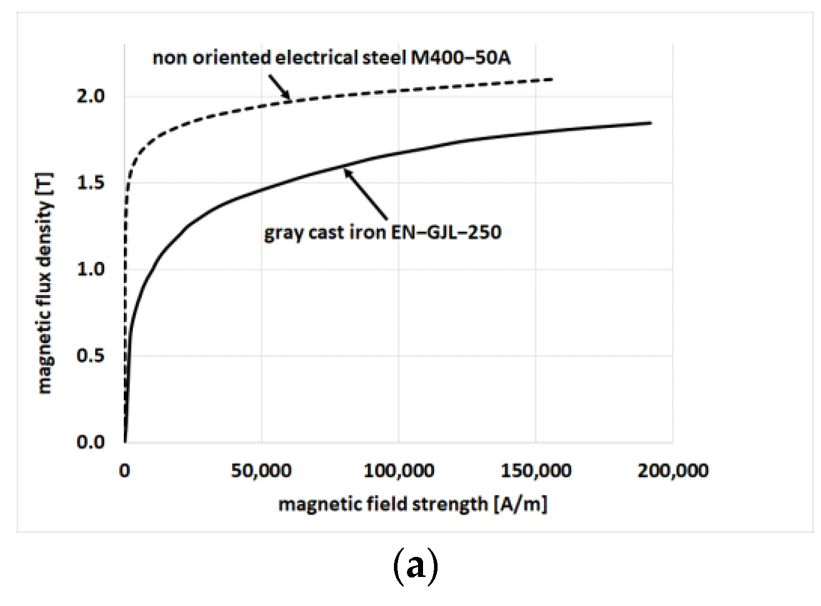
  30. Properties of Electrical Steel M400-50A. Available online: https://www.tatasteeleurope.com/sites/default/files/m400-50a.pdf (accessed on 17 November 2023).
  31. Properties of Grey Cast Iron. Available online: https://www.steel-foundry.com/news/grey-cast-iron-magnetic-properties/ (accessed on 17 November 2023).
  32. Brauer, J. Simple equations for the magnetization and reluctivity curves of steel. IEEE Trans. Magn. 1975, 11, 81. [Google Scholar] [CrossRef]
  33. Mollet, Y.; Barbierato, G.; Gyselinck, J. Finite-element and magnetic-equivalent-circuit modelling of brushed wound-field DC machines with cross-saturation. In Proceedings of the 2018 XIII International Conference on Electrical Machines (ICEM), Lausanne, Switzerland, 4–7 September 2016. [Google Scholar] [CrossRef]
  34. Rizzo, M.; Savini, A.; Turowski, J. Dependence of forces, eddy current and stray losses on screening in power transformers. In Proceedings of the Fifth International Conference on Electrical Machines and Systems ICEMS’2001, Shenyang, China, 18–20 August 2001; Volume 1, pp. 182–185. [Google Scholar] [CrossRef]
  35. Turowski, J.; Turowski, M. Engineering Electrodynamics: Electric Machine, Transformer, and Power Equipment Design, 1st ed.; CRC Press: Boca Raton, FL, USA, 2014. [Google Scholar] [CrossRef]
  36. Opera—Electromagnetic and Electromechanical Simulation. Available online: https://www.3ds.com/products-services/simulia/products/opera/ (accessed on 17 November 2023).
  37. Dems, M.; Komeza, K. Modeling of Static and Dynamic Operating States of Induction Motors; Monograph of the Lodz University of Technology Publishing House: Lodz, Poland, 2011; pp. 1–332. ISBN 978-8-37283-449-2. (In Polish) [Google Scholar]
  38. Li, S.; Gallandat, N.A.; Mayor, J.R.; Habetler, T.G.; Harley, R.G. Calculating the Electromagnetic Field and Losses in the End Region of a Large Synchronous Generator Under Different Operating Conditions With 3-D Transient Finite-Element Analysis. IEEE Trans. Ind. Appl. 2018, 54, 3281–3293. [Google Scholar] [CrossRef]
  39. Lin, R.; Haavisto, A.; Arkkio, A. Axial Flux and Eddy-Current Loss in Active Region of a Large-Sized Squirrel-Cage Induction Motor. IEEE Trans. Magn. 2010, 46, 3933–3938. [Google Scholar] [CrossRef]
  40. Gao, L.; Wang, S.; Li, J. Research on End Structure Losses and Its Suppression Method of High-Speed Canned Induction Motor. IEEE Access 2023, 11, 49913–49923. [Google Scholar] [CrossRef]
  41. Huo, F.; Li, W.; Wang, L.; Zhang, Y.; Guan, C.; Li, Y. Numerical Calculation and Analysis of Three-Dimensional Transient Electromagnetic Field in the End Region of Large Water–Hydrogen–Hydrogen Cooled Turbogenerator. IEEE Trans. Ind. Electron. 2014, 61, 188–195. [Google Scholar] [CrossRef]
  42. Xu, G.; Wang, L.; Zhan, Y.; Zhao, H. Loss Distribution in Stator End Region of Turbo-generators During Asynchronous Operation after Loss of Field. In Proceedings of the 2022 IEEE Industry Applications Society Annual Meeting (IAS), Detroit, MI, USA, 9–14 October 2022; pp. 1–6. [Google Scholar] [CrossRef]
  43. Wang, L.; Huo, F.; Li, W.; Zhang, Y.; Li, Q.; Li, Y.; Guan, C. Influence of Metal Screen Materials on 3-D Electromagnetic Field and Eddy Current Loss in the End Region of Turbogenerator. IEEE Trans. Magn. 2013, 49, 939–945. [Google Scholar] [CrossRef]
  44. Fricke, T.; Schwarz, B.; Ponick, B. A Fast Calculation Approach for Pressure Finger Losses in Large Salient-Pole Synchronous Machines. IEEE Trans. Magn. 2021, 57, 1–7. [Google Scholar] [CrossRef]
  45. Cavagnino, A.; Vaschetto, S.; Ferraris, L.; Gmyrek, Z.; Agamloh, E.B.; Bramerdorfer, G. Striving for the Highest Efficiency Class with Minimal Impact for Induction Motor Manufacturers. IEEE Trans. Ind. Appl. 2020, 56, 194–204. [Google Scholar] [CrossRef]
Figure 1. Division of unit production motors with shaft heights of 315 mm or more depending on their efficiency classes for LV (a) and HV (b) motors.
Electronics 13 00119 g001
Figure 2. Magnetization characteristics of the gray cast iron and electrical steel M400-50A (a) and relative magnetic permeability of the frame material (gray cast iron) in the entire range of magnetic field strength (b) and for magnetic field strength < 2000 A/m (c) [31,32,33]. In (c), the solid line corresponds to the measurement, and the dashed line to the approximation.
Electronics 13 00119 g002aElectronics 13 00119 g002b
Figure 3. Mapping of the boundary of the motor yoke as a boundary of the conductive half-space.
Electronics 13 00119 g003
Figure 4. Exemplary low-power induction motor for linear model validation (dimensions in mm). Simulation for the rated load. At the edge of the outer airspace, the field is assumed to be tangential.
Electronics 13 00119 g004
Figure 5. Magnetic field strength versus distance from the edge of the frame (black—data, red—approximation).
Electronics 13 00119 g005
Figure 6. The ELIC correcting factor for eddy current losses with quadratic polynomial approximation (black—data, red—approximation).
Electronics 13 00119 g006
Figure 7. The ELIC correcting factor for eddy current losses with a linear approximation for induction range up to 0.8 T (black—data, red—approximation).
Electronics 13 00119 g007
Figure 8. The ELIC correcting factor for eddy current losses with a linear approximation for induction range above 0.8 T (black—data, red—approximation).
Electronics 13 00119 g008
Figure 9. The HLIC correcting factor for hysteresis losses with a linear approximation for induction (black—data, red—approximation).
Electronics 13 00119 g009
Figure 10. The HLIC correcting factor for hysteresis losses with a logarithmic approximation for magnetic field strength (black—data, red—approximation).
Electronics 13 00119 g010
Figure 11. Magnitude of flux density for motor A for angle ωt = 0 at rated load.
Electronics 13 00119 g011
Figure 12. Maximum magnitude of flux density only in frame for motor A.
Electronics 13 00119 g012
Figure 13. Magnitude of flux density for motor B for angle ωt = 0 at rated load.
Electronics 13 00119 g013
Figure 14. Maximum magnitude of flux density only in frame for motor B.
Electronics 13 00119 g014
Table 1. The basic rated parameters and main dimensions of investigated motors.
QuantityUnitMotor AMotor B
Rated power PNkW1501250
Rated line voltage UNV1000 (Y)6000 (Y)
Rated current INA110149
Number of poles 2p-410
Power factor cos φR-0.840.84
Rated efficiency ηR%94.096.2
Rotation speed nRrpm1472596
The outer diameter of the stator core Dsemm5201230
The inner diameter of the stator core Dsimm334950,
Stator core length Lsmm232540
Stator yoke height hsy0mm36.761.0
Number of stator slots-72120
Number of rotor slots-60140
Number of serial turns-78200
Air gap thicknessmm13
Table 2. The results of magnetic induction and loss calculations in the yoke and frame obtained by the analytical method and the field-circuit method calculations for motor A.
QuantityUnitMotor A
Analytical CalculationField-Circuit Simulation
Induction in the yoke without field penetration into the frame Bsy0T2.076-
Reducing the induction in the stator yoke Δ B s y T0.214
Induction in the yoke with field penetration into the frame BsyT1.8621.874
Field strength HsyA/m1661416444
Magnetic induction in the frame BkdT1.1061.143
Penetration depth δ m0.008350.00817
Hysteresis losses in the frameW290 1/499300 1/523
Eddy-current losses in the frameW4571 1/62004494 1/6057
Total frame lossesW4861 1/66994794 1/6580
Stator yoke height without field penetration into the frame hsy0m0.036730.03673
Equivalent stator yoke height hsym0.04096-
Magnetic permeability of the frame µ k d H/m66.6 10−669.6 10−6
1 frame loss values without correction.
Table 3. The results of magnetic induction and loss calculations in the yoke and frame obtained by the analytical method and the field-circuit method calculations for motor B.
QuantityUnitMotor B
Analytical CalculationField-Circuit Simulation
Induction in the yoke without field penetration into the frame Bsy0T1.320-
Reducing the induction in the stator yoke Δ B s y T0.012
Induction in the yoke with field penetration into the frame BsyT1.3081.29
Field strength HsyA/m450.2600.8
Magnetic induction in the frame BkdT0.0770.115
Penetration depth δ m0.005170.00519
Hysteresis losses in the frameW4.8 1/4.95.5 1/5.0
Eddy-current losses in the frameW28.9 1/30.132.7 1/31.6
Total frame lossesW33.7 1/35.038.2 1/36.6
Stator yoke height without field penetration into the frame hsy0m0.06100.0610
Equivalent stator yoke height hsym0.0615-
Magnetic permeability of the frame µ k d H/m173.8 10−6172.2 10−6
1 frame loss values without correction.
Table 4. Comparison of selected operational parameters of motor A, measured and calculated, while taking into account the penetration of the field into the cast iron frame (magnetic frame) and while excluding this phenomenon (non-magnetic frame).
QuantityCalculationMeasurement
Magnetic FrameNon-Magnetic Frame
Rated power PN [W]150,000150,000150,000
Losses in the stator windings Pus [W]341041173504
Losses in the rotor windings Pur [W]378937783869
Mechanical losses Pm [W]554554554
Losses in the frame Pkd [W]6699--
Sum of core losses and additional losses (PFe + Pd) [W] (Losses in the frame Pkd
non included in losses Pd)
4324425911,510
Total losses ∑P [W]18,77612,70819,437
Motor efficiency η [%]88.992.288.5
Current in the stator winding Is [A]118.3129.98120.85
Power factor cos φ [-]0.82460.72350.8103
Table 5. Comparison of selected operational parameters of motor B, measured and calculated, while taking into account the penetration of the field into the cast iron frame (magnetic frame) and while excluding this phenomenon (non-magnetic frame).
QuantityCalculationMeasurement
Magnetic FrameNon-Magnetic Frame
Rated power PN [W]1,250,0001,250,0001,250,000
Losses in the stator windings Pus [W]12,81012,82012,810
Losses in the rotor windings Pur [W]788078807810
Mechanical losses Pm [W]269026902690
Losses in the frame Pkd [W]35--
Sum of core losses and additional losses (PFe + Pd) [W] (Losses in the frame Pkd
non included in losses Pd)
31,92631,94629,520
Total losses ∑P [W]55,34155,33652,830
Motor efficiency η [%]95.895.895.9
Current in the stator winding Is [A]150.0150.0146.3
Power factor cos φ [-]0.83800.83800.8573
Disclaimer/Publisher’s Note: The statements, opinions and data contained in all publications are solely those of the individual author(s) and contributor(s) and not of MDPI and/or the editor(s). MDPI and/or the editor(s) disclaim responsibility for any injury to people or property resulting from any ideas, methods, instructions or products referred to in the content.

