Article

Seismoelectric Coupling Equations of Oil-Wetted Porous Medium Containing Oil and Water

School of Electronic Science and Engineering, University of Electronic Science and Technology of China (UESTC), Chengdu 611731, China
*
Authors to whom correspondence should be addressed.
Electronics 2023, 12(9), 2003; https://doi.org/10.3390/electronics12092003
Submission received: 28 February 2023 / Revised: 21 April 2023 / Accepted: 24 April 2023 / Published: 26 April 2023
(This article belongs to the Special Issue Advances in Electronics Technology)

Abstract

:
For porous medium containing multiphase fluid, such as oil-wetted porous medium with oil–water dual phase fluid, its fluid interface will also produce electric double layer (EDL), which will play a role in the seismoelectric effects. At this time, the principle of seismoelectric effects is more complex. The existing theory for the seismoelectric effects is the Pride theory used in the water-saturated porous formation, which cannot meet the actual needs of the theoretical research of seismoelectric exploration in the porous formation with multiphase fluid. Carbonate porous formations are often oil-wetted; therefore, it is necessary to study the electrokinetic effects of oil-wetted porous medium containing multiphase fluid. In this paper, we treated the oil–water mixture as an effective fluid, and solved the effective elastic parameters and extended the Biot equations to the case of oil-wetted porous medium with oil–water dual phase fluid. We calculated the effective electromagnetic parameters and derived the macroscopic coupling equations of seismoelectric effects and electroseismic effects, and proposed the new electrokinetic coupling coefficients of the oil-wetted porous medium with dual phase fluid. We also deduced the coupling functions of electric and magnetic fields relative to the solid displacement in the homogeneous porous medium, and studied the polarization characteristics of the electric field. We use the derived coupling equations to simulate the seismoelectric logging while drilling in the model of oil-wetted porous formation with dual phase fluid under the excitation of multipole sources. The influence of drill collar wave on the acoustic field and electric field under the excitation of different sources was investigated, which has a certain guiding role in the selection of electrokinetic logging tools.

1. Introduction

The seismoelectric effects refer to the mutual coupling process of the energy of the acoustic field and the energy of the electromagnetic field in the porous medium. Carbonate reservoirs are often oil-wetted porous media [1]. In the oil well logging, the invasion zone of such reservoirs is oil-wetted porous medium with oil–water dual phase fluid. Therefore, the study on the electrokinetic effects of oil-wetted porous medium with dual phase fluid is of great significance for oil exploration.
At present, the research object of seismoelectric effects is mainly water-saturated porous medium. In 1994, Pride proposed the Pride equations to describe the electrokinetic effects of water-saturated porous medium, and gave the expression of macroscopic electrokinetic coupling coefficients [2]. In 1996, Pride and Haartsen studied the reciprocity of electrokinetic fields in saturated porous medium, and deduced the coupling functions of the electromagnetic field relative to the solid displacement of homogeneous porous medium [3]. A large number of studies have also been carried out on water-wetted porous media with multiphase flow. In 2013, Warden and Garambois. et al. treated the gas–liquid mixture as a fluid, extended the Pride theory to the unsaturated porous medium case, and gave the expressions of the electrokinetic coupling coefficients of the unsaturated porous medium by analogy with the saturated porous medium [4]. In 2017, Zyserman and Monachesi. et al. deduced the coupling functions of the electromagnetic field relative to the solid phase displacement in homogeneous unsaturated porous media using the seismoelectric coupling equations proposed by Warden, and carried out numerical simulation of SH-TE mode wave in horizontal layered unsaturated porous medium [5].
Some research has been carried out on the electrokinetic effects of oil-wetted porous formation; however, the existing theory has not studied the seismoelectric coupling equations and the corresponding electrokinetic coupling coefficients in the time-varying case. Alkafeef studied the microcosmic mechanism of acousto-electric conversion in oil saturated pores, and deduced the microscopic coupling coefficient [6]. Jackson used Dullen’s multiphase flow pore model [7] to derive the streaming potential coupling coefficient of oil-wetted porous medium with dual phase fluid [8,9]. However, the used multiphase flow model is too simple, and is far from the actual model in pores.
Zhan and Zhu carried out the numerical simulation of electrokinetic logging while drilling in a water-saturated porous medium [10,11]. The electromagnetic field was calculated by solving the Poisson equation satisfied by the electric potential. In actual seismoelectric logging, the seismoelectric effects produce a time-varying electric field. According to the comparative analysis of Gao, in some cases, the quasi-static field approximation method will produce errors [12]. In 2012, Ren carried out the numerical simulation of the coseismic electromagnetic fields excited by the seismic waves in saturated porous medium [13]. He found that in saturated porous formations, the acousto-electric conversion efficiency of fast longitudinal waves is higher than that of other mode waves. In 2013, Guan conducted numerical simulations of electrokinetic logging while drilling in saturated porous formations under multipole sources excitation, and investigated the velocity-time correlation characteristics of sound and electric fields, as well as the influence of drill collar waves [14]. Guan’s research indicates that the electric field is less affected by the drill collar wave in the electrokinetic logging while drilling in saturated porous formation. In 2015, Zheng conducted a similar study using the quasi-static field method and obtained the same conclusion [15].
Based on the above background, we adopted the Warden’s method, regarded the oil–water mixture as an effective fluid, and extended the Biot theory to the case of oil-wetted porous medium with dual phase fluid. In this paper, we deduced the macroscopic coupling equations of seismoelectric effects in time-varying case, and derived the corresponding electrokinetic coupling coefficients. We derived the coupling functions of the electromagnetic field relative to the solid displacement in homogeneous oil-wetted porous medium with dual phase fluid, and analyzed the polarization characteristics of electric field. We carried out the simulation of the electrokinetic logging while drilling in oil-wetted porous formation with dual phase fluid. We introduced the Hertz vector potential, and treated the electromagnetic field as a time-varying field. We also investigated the influence of the drill collar wave on the acoustic and electric fields under the excitation of multipole sources.

2. Methods

2.1. Seismoelectric Coupling Equations

When oil-wetted porous medium contains dual phase fluid, the acoustic field model is more complicated than that of a water-saturated porous medium. In order to simplify the model, the method of warden is adopted in this paper to equate to the oil–water fluid mixture to a fluid, and the Biot equations are extended to the case of oil-wetted porous medium containing dual phase fluid:
{ τ = ω 2 ( ρ u s + ρ f u f s ) τ = ( H 2 G ) ( u s ) I + C ( u f s ) I + G ( u s + u s T ) p = C u s + M u f s u f s = ϕ ( u f u s )
The Biot equations can be found in Ref. [2]. Where τ denotes the stress tensor, ρ denotes the density of the oil-wetted porous medium with dual phase fluid, u s denotes the solid displacement, ρ f denotes the effective fluid density, u f s denotes the seepage displacement of the equivalent fluid, G denotes the formation shear modulus, H , C and M denote the elastic modulus of the porous medium, K s , K f and K b are the bulk modulus of solid matrix, liquid and solid skeleton, respectively, p denotes the acoustic pressure, ϕ denotes the porosity, and u f denotes the displacement of the equivalent fluid.
The electromagnetic field satisfies the following equations:
{ × E = j ω B × H = j ω D + J D = ε E B = μ H
Equation (2) represents the laws that macroscopic electromagnetic fields satisfy at frequency domain, including induction law, Ampere’s law, the constitutive relationship of electric field, and the constitutive relationship of magnetic field. E represents the electric field intensity, H represents the magnetic field intensity, B represents the magnetic induction intensity, D represents the electric displacement vector, and μ is the magnetic permeability. J represents the macroscopic current in the medium, including streaming current and conduction current, and is used to describe the macroscopic acousto-electric conversion.
The effective acoustic and electric parameters are calculated in Table 1.
Where ρ o and ρ w are the densities of oil and water, respectively, s w represents the water saturation, η o and η w denote the viscosity of oil and water, respectively, K w denotes the bulk modulus of the water, K o denotes the bulk modulus of the oil, α denotes the tortuosity of the porous medium, k 0 denotes the effective static permeability of the mixed fluid, σ w is the conductivity of the water, F = α / ϕ , ϕ is the porosity, ε 0 denotes the vacuum dielectric constant, ε s , ε w and ε o are the dielectric constants corresponding to the three phases of solid, water, and oil, respectively.
The seismoelectric coupling equations of oil-wetted porous medium with oil–water dual phase fluid are derived below.
The microscopic current in pores satisfies the local equation [22]:
J w = J w s + J w c
where J w s is the microscopic streaming current in pores, and J w c denotes the microscopic conduction current in pores. According to the research of Ref [23], the streaming current in the oil-wetted pores with dual phase fluid is mainly caused by the electric double layer (EDL) at the fluid interface; therefore, J w s can be expressed as follows:
J w s = Q w o v w o
Additionally, J w c can be expressed as follows:
J w c = σ w e w
where Q w o is the net charge density of the EDL near the fluid interface, v w o is the microscopic relative velocity of water to the liquid interface in pores, and e w denotes the microscopic electric field in pores.
According to Slattery’s volume averaging theory, the macroscopic conduction current can be expressed as follows:
J ¯ c = σ E ¯
E ¯ is the macroscopic electric field. According to Ref [23], by defining the flux averaging of Q w o relative to v w o , the macroscopic streaming current of oil-wetted porous medium with dual phase fluid can be expressed as follows:
J ¯ w s = Q w o e f f v ¯ w o
where v ¯ w o denotes the macroscopic relative velocity of water to the liquid interface in the porous medium, and Q w o e f f denotes the effective net residual charge density (ERCD) of two-phase oil-wetted porous medium.
According to Ref [23], it can be deduced that:
v ¯ w o = l v ¯ w s
where l = s w η o s w η o + 2 η w ( 1 s w ) , and v ¯ w s denotes the macroscopic seepage velocity of water in porous medium.
According to Darcy’s law, the effective seepage velocity of fluid can be expressed as follows:
v ¯ f = k 0 η f ( P ¯ + i ω ρ f v ¯ s )
where P ¯ denotes the sound pressure gradient, v ¯ s denotes the solid phase displacement.
Then, v ¯ w s can be deduced as follows:
v ¯ w s = k 0 k w r η f ( P ¯ + i ω ρ f v ¯ s )
where k w r is the aqueous relative permeability.
It can be further deduced that the macroscopic streaming current in porous medium can be expressed as follows:
J ¯ w s = k 0 k w r Q w o e f f η f l ( P ¯ + i ω ρ f v ¯ s )
The seismoelectric coupling coefficient is defined as follows:
L m = k 0 k w r Q w o e f f η f l
Finally, the coupling equation of acousto-electric conversition can be deduced as follows:
J = σ E + L m ( P + ω 2 ρ f u s )
According to the generalized Darcy permeability [24], we can get:
v ¯ f = k 0 η f ( P ¯ + i ω ρ f v ¯ s + F ¯ e )
where F ¯ e = Q w o e f f E ¯ denotes the electric field force.
Similarly, the macroscopic seepage velocity of water in porous medium is obtained:
v ¯ w s = k 0 k w r η f ( P ¯ + i ω ρ f v ¯ s + F ¯ e )
The expression of v ¯ w o can be further deduced:
v ¯ w o = k 0 k w r η f l ( P ¯ + i ω ρ f v ¯ s + F ¯ e )
The electroseismic coupling coefficient is defined as follows:
L e = k 0 k w r Q w o e f f η f l
Finally, the electroseismic coupling equation of two-phase oil-wetted porous medium can be expressed as follows:
i ω u w o = k 0 k w r η f l ( P + ω 2 ρ f u s ) + L e E

2.2. Coupling Functions of the Oil-Wetted Porous Medium with Oil–water Dual Phase Fluid

Referring to the method of Garambois [25], it is assumed that a uniform plane acoustic wave propagates in the oil-wetted porous medium with dual phase fluid, and the electric and magnetic field amplitudes generated by the seismoelectric effect were calculated. According to the seismoelectric coupling equations obtained earlier, we can deduce the wave equations satisfied by the acoustic field, the electric field and the magnetic field, solve the eigenmodes of the wave equations, and we can obtain the following results. When the acoustic field is a longitudinal wave, we assume that e k = e s = e f s = e e , where e s denotes the direction of solid displacement, e f s denotes the direction of seepage velocity of equivalent liquid, and e e denotes the direction of electric field. The direction of all fields is e k .
The corresponding coupling functions are as follows:
{ u f s 0 = β L ξ u s 0 E 0 = i ω ρ ¯ L m ε ¯ β L ξ u s 0
where β L ξ = ( H s ξ 2 ρ C s ξ 2 ρ f ) , s p f and s p s represent the slowness of fast longitudinal wave and slow longitudinal wave, respectively, ρ t = ρ ρ f 2 / ρ ¯ , and ρ ¯ = i ω η f k 0 .
When the acoustic field is SH wave, the direction of each field is e k e s = e k e f s = e k e e = 0 . The electromagnetic field is TE wave, and the direction of other field is: e f s = e e = e s = y , e h = e k × e s . The corresponding coupling functions are as follows:
{ u f s 0 = G ρ f ( s ξ 2 ρ G ) u s 0 E 0 = i ω μ ρ ¯ ρ f L m G β T ξ u s 0 H 0 = i ω s ξ ρ ¯ ρ f L m G β T ξ u s 0
When the sound field is SV wave, the electromagnetic field is TM wave, and the direction of other field is: e f s = e e = e s = y × e k , e h = y . The coupling functions are as follows:
{ u f s 0 = G ρ f ( s ξ 2 ρ G ) u s 0 E 0 = i ω μ ρ ¯ ρ f L m G β T ξ u s 0 H 0 = i ω s ξ ρ ¯ ρ f L m G β T ξ u s 0
where β T ξ = ( s ξ 2 ρ / G s ξ 2 μ ε ¯ ) , s s and s e m represent the slowness of acoustic field shear wave and electromagnetic field, respectively.
It can be seen from the above derivation that for oil-wetted porous medium with dual phase fluid, each mode wave of the sound field can excite the electric field of the corresponding mode, and the polarization direction of the electric field is determined by the solid displacement of the acoustic field.

2.3. Seismoelectric Logging While Drilling

The solution method of the acoustic field in the electrokinetic logging while drilling in the oil-wetted porous medium with dual phase fluid is the same as that of Zhan and Zhu [10,11], except that the formation parameters of the acoustic field adopt the effective parameters obtained above. The solution process of electromagnetic field is different from the two.
Ignoring the coupling effect of electric field on acoustic field, and according to Equations (11) and (16), the streaming current in the porous medium can be expressed as follows:
J s = i ω L m η f / ( k k w r l ) u w o
Therefore, the streaming current in porous formation can be expressed with the potential function of acoustic field:
J s = ψ 1 + ψ 2 + × F 1 + × × F 2
where ψ 1 , ψ 2 , F 1 and F 2 are the potential functions of sound field.
According to the theory of electrodynamics, any current source J can be expressed as follows:
J = P t + × M
where P is the current source without divergence, M is the current source without curl.
If the Hertz electric vector Π e and the Hertz magnetic vector Π m satisfy, respectively:
{ ( 2 μ ε ¯ 2 t 2 ) Π e = P ε ¯ ( 2 μ ε ¯ 2 t 2 ) Π m = M
Then, the electric field and magnetic field expressed by Hertz vector are as follows:
{ E = Π e + k e m 2 Π e + i ω μ × Π m H = i ω ε ¯ × Π m + × × Π m
When the excitation source is streaming current, there is:
{ P t = ψ 1 + ψ 2 × M = × F 1 + × × F 2
By substituting Equation (27) into Equation (25), the problem of solving Maxwell equations excited by streaming current is transformed into vector Helmholtz equations about Hertz vector.
{ ( 2 μ ε ¯ 2 t 2 ) Π e = ψ 1 + ψ 2 i ω ε ¯ ( 2 μ ε ¯ 2 t 2 ) Π m = F 1 × F 2
By solving the special solution and substituting the result into Equation (26), we can obtain the special solution of electromagnetic field in porous formation as follows: E 1 , E 2 , E 3 and E 4 .
The electromagnetic field in the passive case only needs two independent scalar functions to represent. Let Π e = Π e e z , Π m = Π m e z ; then, we have:
{ 2 Π e + k e m 2 Π e = 0 2 Π m + k e m 2 Π m = 0
Then, the Hertz vector potential of the passive electromagnetic field in the borehole fluid is as follows:
{ Π 0 e = R e A e I n ( η e m 1 r ) + R e B e K n ( η e m 1 r ) Π 0 m = R e A m I n ( η e m 1 r ) + R e B m K n ( η e m 1 r )
Substitute the expressions of Π 0 e and Π 0 m into Equation (26) to obtain the expression of the electromagnetic field ( E b and H b ) in the borehole.
The Hertz vector potential of the passive electromagnetic field in the porous medium is as follows:
{ Π 20 e = R e B e 2 K n ( η e m 2 r ) Π 20 m = R e B m 2 K n ( η e m 2 r )
Substitute the expressions of Π 20 e and Π 20 m into Equation (26) to obtain the passive electromagnetic field in the porous medium as E 0 and H 0 .
The expression of the electromagnetic field induced by the acoustic wave in the porous medium is as follows:
{ E = E 1 + E 2 + E 3 + E 4 + E 0 H = H 1 + H 2 + H 3 + H 4 + H 0
In the LWD model, the boundary conditions satisfied by the electromagnetic fields are as follows:
The tangential electric field on the surface of the tool layer is 0:
E b z ( R t ) = 0
The tangential components of the electric and magnetic fields on the wall of the well are continuous:
{ E b z ( R b ) = E f z ( R b ) H b φ ( R b ) = H f φ ( R b )
R t is the outer surface radius of the tool layer and R b is the wellbore radius. According to the boundary conditions, list the equations, solve the equations to obtain the unknown coefficients, and substitute them into the expression of the electromagnetic field in the wellbore to obtain the electromagnetic field ( E b and H b ) on the wall of the well.
The sound pressure in the borewhole is as follows:
P ( r ) = ρ w ω 2 [ A n I n ( k ρ r ) + B n ( k ρ r ) ] cos n θ
A n and B n are the coefficients of acoustic potential functions, which are solved in Ref [11]. k ρ is the radial wavenumber.

3. Simulation and Analysis

In this section, we carried out numerical simulation on the electrokinetic logging while drilling in oil-wetted porous medium with dual phase fluid under the excitation of multipole sources. We have compared and analyzed the received acoustic field and electric field, investigated their frequency–velocity correlation characteristics, and analyzed the influence of drill collar wave on the electrokinetic fields.
The center frequency of the excitation source is 7 KHz, which is excited by a monopole source, a dipole source, and a quadrupole source, respectively. There is a total of seven receiving sites on the wall of the well: the first site is at z = 1.3713 m, and the distance between adjacent sites is 0.1524 m. The parameters of the formation are shown in Table 2.
In the following figures, t represents the time, P represents the acoustic pressure, Ez represents the axial electric field, V represents the group velocity, and f represents the frequency.
The frequency–velocity correlation characteristics of sound and electric fields are obtained through the principle of multiple filtering [26]. First, preprocess the original seismic signal by removing zero drift and tendency. Transform the signal into the frequency domain through Fourier transform and then use a narrowband bandpass digital filter to filter the signal, the frequency components outside the passband are filtered out. Then, the signal is transformed into the time domain by inverse Fourier transform. The amplitude is calculated using Hilbert transform, and find the time corresponding to the maximum amplitude, that is, the arrival time of the wave packet corresponding to the central frequency. Through the above process, the amplitude and group velocity of the signal can be found. Repeat the above steps until the group velocity values of all the desired frequencies (periods) are obtained.
Figure 1 shows the comparison of electric field and acoustic field in the electrokinetic logging while drilling in the oil-wetted porous formation with dual phase fluid under the excitation of monopole source. It can be seen from the figure that the waveforms of electric field and acoustic field are very similar, which shows that under the excitation of monopole source, each mode wave of acoustic field will excite the corresponding mode electric field. The electro-acoustic ratio of the fast longitudinal wave is relatively larger, which indicates that the acousto-electric conversion efficiency of the fast longitudinal wave is higher.
Figure 2a,b shows the frequency–velocity correlation characteristics of sound field and electric field in the electrokinetic logging while drilling in the oil-wetted porous formation with dual phase fluid under the excitation of monopole source. The drill collar wave velocity is about 5940 m/s. It can be seen from Figure 2a that the bright spots near the velocity of the drill collar wave are very obvious, and the sound field is greatly affected by the drill collar wave. It can be seen from Figure 2b that the bright spots near the drill collar wave velocity are much smaller, and the electric field is less affected by the drill collar wave than the acoustic field. The velocity of the fast longitudinal wave in the formation is 4000 m/s. Compared with the acoustic field, the bright spot of the electric field near the fast longitudinal wave is larger, the electro-acoustic ratio of the fast longitudinal wave is relatively larger, and the acousto-electric conversion ability of the fast longitudinal wave is stronger than other mode waves. By comparing Figure 2a,b, it can be found that under the excitation of monopole source, measuring electric field can avoid the influence of drill collar wave to a certain extent, and makes it easier to measure the longitudinal wave velocity.
Figure 3 shows the comparison of the electric field and the acoustic field in the electrokinetic logging while drilling in the oil-wetted porous formation with dual phase fluid under the excitation of dipole source. It can be seen from the figure that the waveforms of the electric field and the acoustic field are very similar, which shows that under the excitation of the dipole source, each mode wave of the acoustic field will stimulate the electric field of the corresponding mode. The electro-acoustic ratio of the fast longitudinal wave is relatively larger, which indicates that the acousto-electric conversion efficiency of the fast longitudinal wave is higher.
Figure 4a,b shows the frequency–velocity correlation characteristics of sound field and electric field in the electrokinetic logging while drilling in the oil-wetted porous formation with dual phase fluid under the excitation of dipole source. The drill collar wave velocity is about 5940 m/s. It can be seen from Figure 4a that the bright spot near the velocity of the drill collar wave is very dark, and the drill collar wave has very little effect on the acoustic field. It can be seen from Figure 4b that the bright spot near the drill collar wave is smaller, and the electric field is less affected by the drill collar wave, which can be almost ignored. Through analysis, it can be deduced that the influence of drill collar wave can be ignored in the electrokinetic logging while drilling under the excitation of dipole source.
Figure 5 shows the comparison of electric field and acoustic field in the electrokinetic logging while drilling in the oil-wetted porous formation with dual phase fluid under the excitation of quadrupole source. It can be seen from the figure that the waveforms of the electric field and the acoustic field are very similar, which shows that under the excitation of the quadrupole source, each mode wave of the acoustic field will stimulate the electric field of the corresponding mode. The electro-acoustic ratio of the fast longitudinal wave is relatively larger, which indicates that the acousto-electric conversion efficiency of the fast longitudinal wave is higher.
Figure 6a,b shows the frequency–velocity correlation characteristics of sound field and electric field in the electrokinetic logging while drilling in the oil-wetted porous formation with dual phase fluid under the excitation of quadrupole source. The drill collar wave velocity is about 5940 m/s. It can be seen from Figure 6a that the bright spots near the velocity of the drill collar wave are very obvious, and the sound field is greatly affected by the drill collar wave. It can be seen from Figure 6b that the bright spots near the drill collar wave velocity are also obvious, but are much smaller compared with that of acoustic field. The drill collar wave also has influence on the electric field; however, compared with the acoustic field, the drill collar wave has much less influence on the electric field.

4. Discussion

From Equations (19)–(21), it can be seen that each mode wave of the acoustic field will excite the electric field of the corresponding mode. The comparison of sound field and electric field in Figure 1, Figure 3 and Figure 5 can also prove that under the excitation of multipole sources, each mode wave of acoustic field in the stratum can excite the accompanying electric field.
By observing Figure 1, Figure 3 and Figure 5, we can find that the electro-acoustic ratio of fast longitudinal wave is relatively larger. This is consistent with the research results of saturated porous medium [13]. By comparing Figure 2a,b, Figure 4a,b and Figure 6a,b, it can also be found that the bright spot near the fast longitudinal wave velocity is brighter in the correlation characteristic diagram of the electric field, which can also verify the above conclusion.
From Figure 1, Figure 3 and Figure 5, it can be seen that for the fast longitudinal wave part, the electric field and the acoustic field are reversed, while for other mode wave parts, the electric field and the acoustic field are in the same direction. The conduction current and streaming current should be in the opposite direction; therefore, the electric field and streaming current are in the opposite direction. According to Equation (9), the longitudinal wave part of seepage velocity is mainly composed of liquid phase velocity, and the liquid is positively charged; therefore, the electric field corresponding to the longitudinal wave part is opposite to the direction of the acoustic field. According to Equation (9), the other mode wave part of seepage velocity is mainly determined by the solid phase velocity, and the solid phase surface is negatively charged; therefore, the electric field corresponding to the other mode wave parts is in the same direction with the acoustic field.
By comparing Figure 2a,b, Figure 4a,b and Figure 6a,b, it can be found that the electric field in the electrokinetic logging while drilling in the oil-wetted porous formation with dual phase fluid is much less affected by the drill collar wave than the acoustic field, which is an advantage of electrokinetic logging. This is consistent with the research results of saturated porous medium [14,15]. At the same time, it can also be found that under the excitation of dipole source, the influence of drill collar wave can be almost ignored. This proves that the use of dipole source excitation can effectively avoid the impact of drill collar wave in the electrokinetic logging while drilling.

5. Conclusions

In this paper, we studied the electrokinetic effects in a oil-wetted porous medium with dual phase fluid, derived the seismoelectric coupling equations, deduced the coupling functions of electric field and magnetic field relative to solid displacement of acoustic field in a homogeneous porous medium, and investigated the polarization characteristics of electric field. We also conducted numerical simulation of the electrokinetic logging while drilling in an oil-wetted porous formation with dual phase fluid. We can draw the following conclusions through the research:
(1)
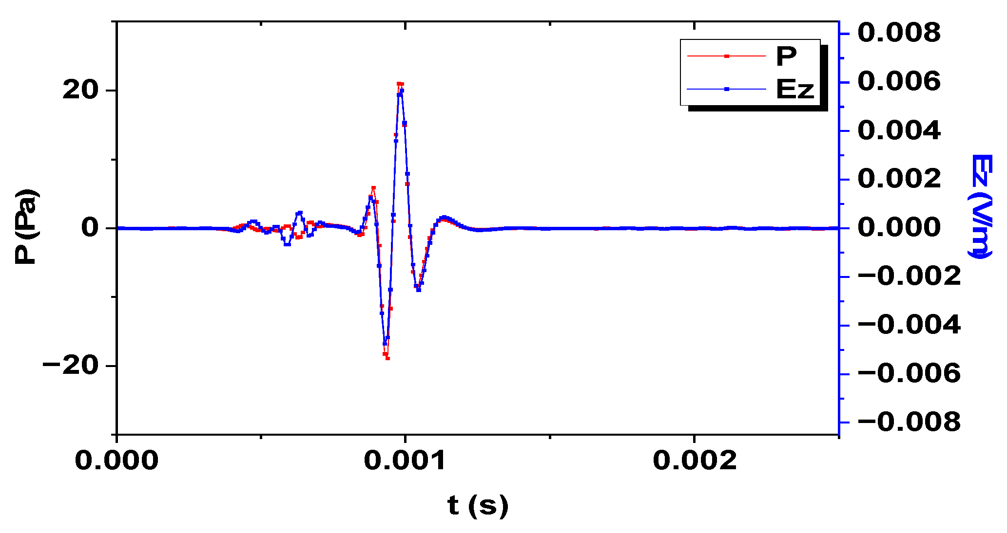
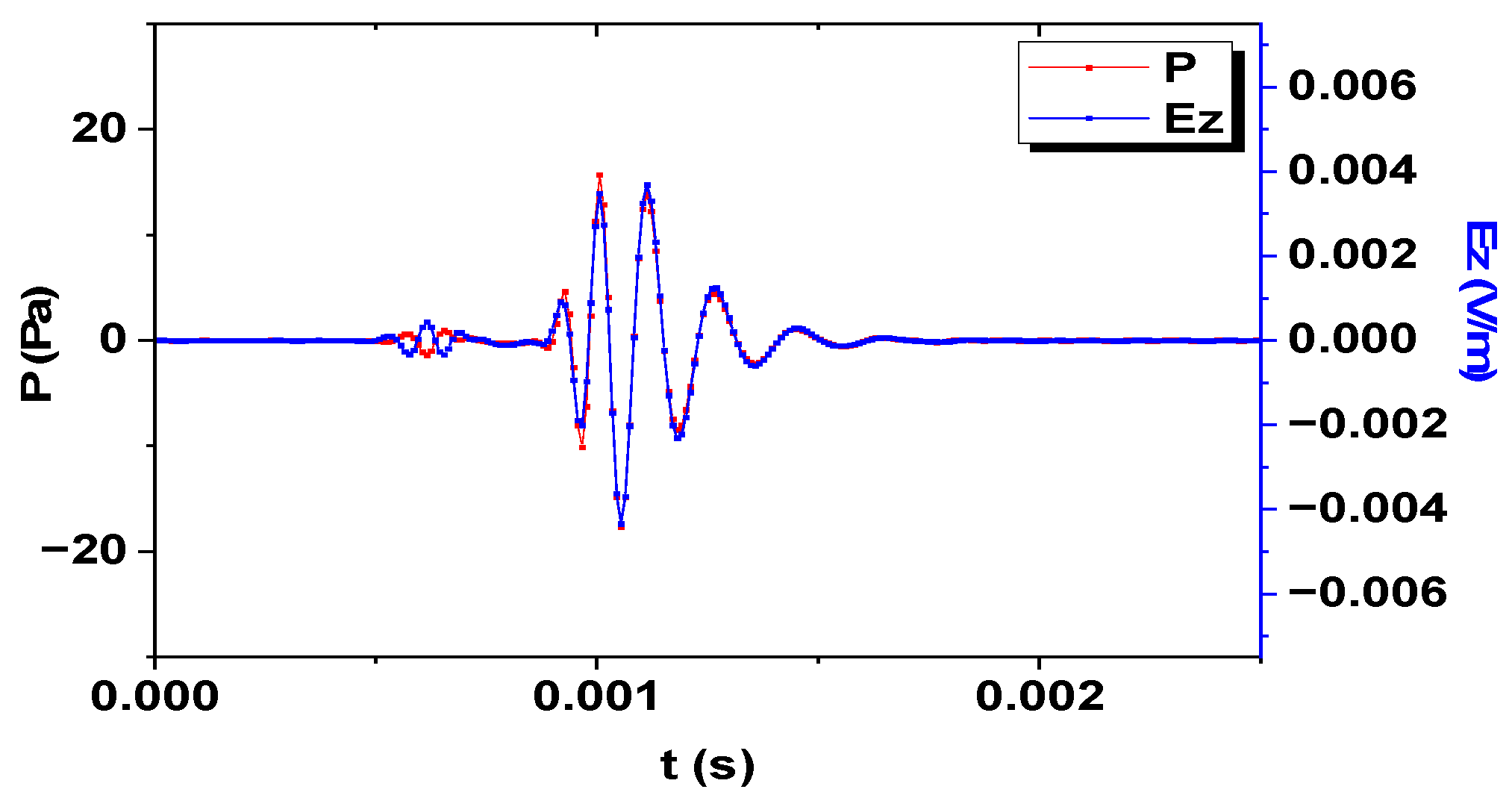
The polarization direction of the electric field generated by the electrokinetic conversion in the oil-wetted porous medium with dual phase fluid is determined by the acoustic field. For the longitudinal wave part, the direction of the electric field is opposite to the sound field, while for other mode waves, the direction of the electric field is the same as the sound field.
(2)
The electrokinetic conversion in the oil-wetted porous medium with dual phase fluid will stimulate the electric field that accompanies each mode wave of the acoustic field; therefore, the electrokinetic logging can measure the acoustic velocity in the formation.
(3)
In the electrokinetic logging, the electrokinetic conversion efficiency of fast longitudinal wave is higher than that of other mode waves.
(4)
In electrokinetic logging while drilling, the electric field is less affected by the drill collar wave than the acoustic field, which is the advantage of electrokinetic logging.
(5)
In electrokinetic logging, while drilling in the oil-wetted porous formation with dual phase fluid, using dipole source excitation can effectively avoid the influence of drill collar wave.

Author Contributions

Conceptualization, Y.Z., X.S. and Z.N.; Methodology, Y.Z. and X.S.; Software, Y.Z.; Validation, Y.Z.; Formal analysis, Y.Z. and X.S.; Investigation, Y.Z. and Z.N.; Resources, Y.Z.; Data curation, Y.Z. and X.S.; Writing—original draft, Y.Z.; Writing—review and editing, Z.N.; Visualization, X.S.; Supervision, Z.N.; Project administration, X.S. and Z.N.; Funding acquisition, X.S. and Z.N. All authors have read and agreed to the published version of the manuscript.

Funding

This research was supported by the National Science Foundation of China (Grant No. 61727803).

Data Availability Statement

Data is unavailable due to privacy and ethical restrictions.

Conflicts of Interest

The authors declare no conflict of interest.

References

  1. Revil, A.; Jardani, A.; Sava, P.; Haas, A. The Seismoelectric Method: Theory and Applications, 1st ed.; John Wiley & Sons: The Atrium, UK, 2015; pp. 258–259. [Google Scholar]
  2. Pride, S. Governing equations for the coupled electromagnetics and acoustics of porous media. Phys. Rev. B 1994, 50, 15678. [Google Scholar] [CrossRef] [PubMed]
  3. Pride, S.R.; Haartsen, M.W. Electroseismic wave properties. J. Acoust. Soc. Am. 1996, 100, 1301–1315. [Google Scholar] [CrossRef]
  4. Warden, S.; Garambois, S.; Jouniaux, L.; Brito, D.; Sailhac, P.; Bordes, C. Seismoelectric wave propagation numerical modelling in partially saturated materials. Geophys. J. Int. 2013, 3, 1498–1513. [Google Scholar] [CrossRef]
  5. Zyserman, I.; Monachesi, L.B.; Jouniaux, L. Dependence of shear wave seismoelectrics on soil textures: A numerical study in the vadose zone. Geophys. J. Int. 2017, 3, 918–935. [Google Scholar] [CrossRef]
  6. Alkafeef, S.; Gochin, R.J.; Smith, A.L. The effect of double layer overlap on measured streaming currents for toluene flowing through sandstone cores. Colloids Surf. A Physicochem. Eng. Asp. 2001, 195, 77–80. [Google Scholar] [CrossRef]
  7. Dullien, F. Porous Media: Fluid Transport and Pore Structure; Academic Press: Cambridge, MA, USA, 2013. [Google Scholar]
  8. Jackson, M.D. Characterization of multiphase electrokinetic coupling using a bundle of capillary tubes model. J. Geophys. Res. Solid Earth 2008, 113, B04201. [Google Scholar] [CrossRef]
  9. Jackson, M.D. Multiphase electrokinetic coupling: Insights into the impact of fluid and charge distribution at the pore scale from a bundle of capillary tubes model. J. Geophys. Res. Solid Earth 2010, 115, B07206. [Google Scholar] [CrossRef]
  10. Zhan, X.; Chi, S.; Toksöz, M.N. Simulation of the converted electric field during multipole logging while drilling (LWD). In Proceedings of the 2006 SEG Annual Meeting, New Orleans, LA, USA, 1–6 October 2006. [Google Scholar]
  11. Zhu, Z.; Chi, S.; Toksoz, M.N. Experimental and theoretical studies of seismoelectric effects in boreholes. Commun. Comput. Phys. 2008, 3, 109–120. [Google Scholar]
  12. Gao, Y.; Huang, F.; Hu, H. Comparison of full and quasi-static seismoelectric analytically-based modeling. J. Geophys. Res. Solid Earth 2017, 122, 8066–8106. [Google Scholar] [CrossRef]
  13. Ren, H.; Chen, X.; Huang, Q. Numerical simulation of coseismic electromagnetic fields associated with seismic waves due to finite faulting in porous media. Geophys. J. Int. 2012, 3, 925–944. [Google Scholar] [CrossRef]
  14. Guan, W.; Hu, H.; Zheng, X. Theoretical simulation of the multipole seismoelectric logging while drilling. Geophys. J. Int. 2013, 195, 1239–1250. [Google Scholar] [CrossRef]
  15. Zheng, X.; Hu, H.; Guan, W.; Wang, J. Simulation of the borehole quasistatic electric field excited by the acoustic wave during logging while drilling due to electrokinetic effect. Geophysics 2015, 80, D417–D427. [Google Scholar] [CrossRef]
  16. Batzle, M.L.; Wang, Z. Seismic properties of pore fluids. Geophysics 1992, 57, 1396–1408. [Google Scholar] [CrossRef]
  17. Teja, A.S.; Rice, P. Generalized corresponding states method for the viscosities of liquid mixtures. Ind. Eng. Chem. Fundam. 1981, 20, 77–81. [Google Scholar] [CrossRef]
  18. Carcione, J.M.; Picotti, S.; Gei, D.; Rossi, G. Physics and Seismic Modeling for Monitoring CO2 Storag. Pure Appl. Geophys. 2006, 163, 175–207. [Google Scholar] [CrossRef]
  19. Liu, G.; Butler, J.J.; Knobbe, R.S. Hydraulic conductivity profiling with direct push methods. Grundwasser 2012, 17, 19–29. [Google Scholar] [CrossRef]
  20. Archie, G.E. The electrical resistivity log as an aid in determining some reservoir characteristics. Trans. Aime 1942, 146, 54–62. [Google Scholar] [CrossRef]
  21. Birchak, J.R.; Gardner, C.G.; Hipp, J.E.; Victor, J.M. High dielectric constant microwave probes for sensing soil moisture. Proc. IEEE 1974, 62, 93–98. [Google Scholar] [CrossRef]
  22. Revil, A.; Linde, N.; Cerepi, A.; Jougnot, D.; Matthäi, S.; Finsterle, S. Electrokinetic coupling in unsaturated porous media. J. Colloid Interface Sci. 2007, 313, 315–327. [Google Scholar] [CrossRef]
  23. Zhao, Y.; Sun, X.; Nie, Z. Seismoelectric Effect of Oil-Wetted Porous Media Containing Two-Phase Flow. Electronics 2023, 12, 346. [Google Scholar] [CrossRef]
  24. Jardani, A.; Revil, A.; Slob, E.; Söllner, W. Stochastic joint inversion of 2D seismic and seismoelectric signals in linear poroelastic materials: A numerical investigation. Geophysics 2010, 75, N19. [Google Scholar] [CrossRef]
  25. Garambois, S.; Dietrich, M. Seismoelectric wave conversions in porous media: Field measurements and transfer function analysis. Geophysics 2001, 66, 1417–1430. [Google Scholar] [CrossRef]
  26. Dziewonski, A.; Bloch, S.; Landisman, M.A. technique for the analysis of transient seismic signals. Bull. Seismol. Soc. Am. 1969, 59, 427–444. [Google Scholar] [CrossRef]
Figure 1. Comparison of electric field and acoustic field (monopole source).
Electronics 12 02003 g001
Figure 2. Correlation characteristics of the seismoelectric fields (monopole source): (a) acoustic field; (b) electric field.
Electronics 12 02003 g002
Figure 3. Comparison of electric field and acoustic field (dipole source).
Electronics 12 02003 g003
Figure 4. Correlation characteristics of the seismoelectric fields (dipole source): (a) acoustic field; (b) electric field.
Electronics 12 02003 g004
Figure 5. Comparison of electric field and acoustic field (quadrupole source).
Electronics 12 02003 g005
Figure 6. Correlation characteristics of the seismoelectric fields (quadrupole source): (a) acoustic field; (b) electric field.
Electronics 12 02003 g006
Table 1. Effective parameters.
Effective Parameters
Effective density [16] ρ f ( s w ) = ( 1 s w ) ρ o + s w ρ w
Effective viscosity [17] η f ( s w ) = η o ( η w / η o ) s w
Effective fluid bulk modulus [18] K f ( s w ) = ( K w K o ) s w 5 + K o
Effective critical frequency [19] ω c ( s w ) = ϕ η f ( s w ) α k 0 ρ f ( s w )
Conductivity [20] σ ( s w ) = s w n F σ w
Dielectric constant [21] ε ( s w ) = ε 0 [ ( 1 ϕ ) ε s + ϕ s w ε w + ϕ ( 1 s w ) ε o ] 2
Table 2. Parameters of oil wetted porous formation with dual phase fluid.
ParameterValueUnit
Static permeability k 0 10 12 m 2
Porosity ϕ 0.2Dimensionless
Water phase viscosity η w 0.001 Pa m
Oil phase viscosity η o 0.1 Pa m
Water phase density ρ w 1000 kg / m 3
Oil phase density ρ o 776 kg / m 3
Solid matrix density ρ s 2650 kg / m 3
Skeleton shear modulus G 13.99 GPa
Skeleton bulk modulus K b 14.4 GPa
Elastic modulus of skeleton K s 35.73 GPa
Bulk modulus of water K w 2.25 GPa
Bulk modulus of oil K o 1.29 GPa
Water saturation s w 0.9Dimensionless
Tortuosity α 2Dimensionless
Disclaimer/Publisher’s Note: The statements, opinions and data contained in all publications are solely those of the individual author(s) and contributor(s) and not of MDPI and/or the editor(s). MDPI and/or the editor(s) disclaim responsibility for any injury to people or property resulting from any ideas, methods, instructions or products referred to in the content.

