Article

System-Level Consideration and Multiphysics Design of Propulsion Motor for Fully Electrified Battery Powered Car Ferry Propulsion System

1
Electric Machine and Drive System Research Center, Korea Electrotechnology Research Institute, Changwon 51543, Republic of Korea
2
Energy and Power Conversion Engineering Department, Korea University of Science and Technology, Daejeon 34113, Republic of Korea
*
Authors to whom correspondence should be addressed.
These authors contributed equally to this work.
Electronics 2023, 12(6), 1491; https://doi.org/10.3390/electronics12061491
Submission received: 13 February 2023 / Revised: 17 March 2023 / Accepted: 20 March 2023 / Published: 22 March 2023

Abstract

:
The Korean government is facing growing concern over the increasing levels of fine dust. A significant contribution to this problem comes from coastal vessels. To mitigate this, an electric ship propulsion system has been proposed as a solution to reduce air pollution. The application of a fully electric propulsion system in a ship is challenging due to size, capacity limitations, and the cost investment of the battery system. To address the challenges of battery limitation and initial investment costs, the development and supply of removable battery supply systems (RBSSs) for fully electrified battery powered (F-EBP) car ferries are studied. A permanent magnet synchronous motor (PMSM) for the F-EBP car ferry using a roll-on/roll-off-type RBSS is developed in this work. Firstly, the concept of the F-EBP car ferry is discussed, and the specifications of the electric car ferry propulsion system are provided. Secondly, motor design and electromagnetic analysis are performed using finite-element analysis (FEA), where the heat sources including copper loss, core loss, and PM loss are calculated. Mechanical loss is also considered. Finally, a thermal network of the motor is built considering the lumped-parameter model. The results of the thermal analysis indicate that the motor operates within the safe region and can perform well in rated working conditions.

1. Introduction

1.1. Background

Given that approximately 80% of global trade is conducted via sea [1], there is increasing pressure on maritime organizations and ship system designers to find ways to limit the environmental impact of shipping. In response to this, the International Maritime Organization (IMO) has introduced stringent regulations aimed at improving the design of ship systems, including the Energy Efficiency Existing Ship Index (EEXI) [2] and the Carbon Intensity Indicator (CII), which are set to come into effect in January 2023 [3,4]. These regulations pose a significant challenge for engineers, who must continuously seek out new technologies and ways to improve the efficiency of existing systems throughout the ship design process.
South Korea has an export-oriented economy, despite limited natural resources. In recent years, it has seen tremendous growth as one of the fastest-growing economies in the Organization for Economic Co-operation and Development (OECD), though this growth has come at the cost of the environment, particularly air pollution. Air pollutants and fine dust from coastal ships in South Korea are a growing concern due to the negative impacts they have on the environment and human health. Coastal ships are a major source of air pollution in South Korea, emitting harmful substances such as sulfur dioxide (SO2), nitrogen oxides (NOx), and particulate matter into the atmosphere. Fine dust, also known as PM2.5, refers to particulate matter with a diameter of smaller than 2.5 μm, which can penetrate deep into the lungs and cause serious health problems. The coastal shipping industry in the Republic of Korea is responsible for a significant portion of the fine dust emissions in the country. One large container ship is capable of emitting the same amount of fine dust as 500,000 trucks and the same amount of sulfur oxide as 50 million diesel cars [5]. Additionally, 15 heavy-oil ships emit more harmful oxides, such as sulfur and nitrogen oxides, than all cars worldwide [6]. The emissions from ships, including non-road pollutants, are estimated to make up 12% of the fine dust in the Republic of Korea, with shipping emissions accounting for over 5% [7]. To address this problem, the South Korean government has implemented various measures to reduce air pollution from coastal ships. These measures include stricter emission regulations for marine engines, the use of cleaner fuels, and the promotion of advanced technologies to reduce emissions. In addition, the government is also promoting the use of electric and hybrid ships, which have lower emissions compared to traditional diesel-powered ships.

1.2. Bibliography Review

In recent years, the advancement of power electronics and lithium battery technologies has made fully electrified battery powered (F-EBP) ships a viable solution for meeting zero-emission regulations in maritime applications [8,9]. The decreasing cost and increasing energy density of batteries through technology development make F-EBP ships promising for commercialization and expansion. Compared to traditional diesel propulsion motors or geared gas turbines, F-EBP propulsion motors offer several advantages, such as superior dynamics, greater flexibility in accommodating electrical motors, reduced energy consumption, reduced vibration for improved comfort, and a higher level of automation in engine rooms [10]. The main drawback of F-EBP propulsion ships is that they require large batteries, making them inefficient for operating the main propulsion motors of sailing ships on the oceans or unspecified pathways. The high cost of batteries also leads to the building cost of an F-EBP ship being almost twice as much as an engine-powered ship with similar specifications. Moreover, when batteries are installed in ships, a mismatch between the battery replacement life of 10 years and the ship operating life of 25 years can result in unintended operational losses, leading to economic losses for the shipping company. However, F-EBP propulsion is a useful sustainable and environment-friendly solution for ships that emit no pollutants.
As of 2017, there were 9620 domestic registered ships with a total tonnage of 45.73 million, of which 3.4% (326 ships) and 0.5% (240,000 tons) were classified as domestic coastal ships [11]. The Ministry of Oceans and Fisheries, the Republic of Korea, and the Republic of Korea Coast Guard predict that the demand for replacements among the 100,000 registered ships, including fishing boats and leisure ships, will increase as 24,352 (24%) of them are over 20 years old. Therefore, it is necessary to research the fully electrified propulsion system to replace the traditional ship which currently operates over the coast of South Korea. To address the challenges of battery replacement and initial investment costs, the development and supply of removable power supply systems (RPSSs), such as battery systems, is necessary. RPSSs are not permanently installed inside ships and are replaced during every cruise, thereby avoiding operation losses due to differences in service life. With the widespread adoption of RPSSs, an industry capable of effectively operating and maintaining ship batteries is expected to emerge. Through the establishment of an entirely novel ship battery supply company, battery costs can be shared, bringing down the initial investment cost and enhancing the ability to compete of the Republic of Korea coastal maritime industry. Additionally, the implementation of this system would eliminate the need for high-voltage port infrastructure, thereby maintaining safe ports. This development is comparable to the use of affordable electricity on land.
For use in ship propulsion, a variety of motor classes could be taken into consideration, including DC (commutator) motors, traditional induction and synchronous motors, permanent magnet synchronous motors (PMSMs), doubly fed induction machines, and superconducting AC and acyclic homopolar machines [12,13,14]. PMSMs are commonly used because of their high efficiency, high power density, and fast dynamic response. In the case of PMSM technology, there are three basic design types: radial flux (surface [15,16] or interior [17,18,19]) and axial flux [20] PMSMs. The selection of PMSM types for ship propulsion is driven by the specification of propulsion systems.
The thermal performance of the motor, particularly the temperature rise of the stator winding and rotor magnet, determines the life and operating reliability of the motor. A sharp increase in motor temperature can lead to winding insulation failure, significant degradation of the permanent magnet performance, or even complete loss of driving capability. Any local high-temperature breakdown in the motor would result in forced motor stoppage and repair. Therefore, when designing and manufacturing the motor, the improvement of power density and generation of local hot spots must be fully considered to ensure safe and reliable operation of the electric drive system. Consequently, accurate temperature distribution analysis becomes a crucial process in motor design.
There are several well-known approaches for such thermal analysis, including numerical modeling (finite-element analysis (FEA), computation fluid dynamic (CFD)) and lumped-parameter thermal network (LPTN). LPTN is a simpler approach to thermal analysis compared to FEM and CFD, as it models the electric motor as a network of equivalent thermal resistances and capacities. The main advantage of this method is its simplicity, which makes it faster and less computationally expensive compared to FEM and CFD. However, its simplicity also limits its accuracy and versatility, as it does not account for complex heat transfer mechanisms and is not suitable for all types of electric motors.

1.3. Contribution

This article focuses on the design and analysis of a permanent magnet synchronous motor (PMSM) considering multiphysics aspects for an F-EBP car ferry using an RBSS. The aim of this work is to provide the readers with an idea on developing a multiphysics design of the propulsion motor for an F-EBP car ferry using an RBSS considering its system level constraints. The main contributions of the proposed work can be listed as follows:
(i)
A detailed system level energy flow infrastructure for an F-EBP car ferry using an RBSS is proposed showing how DC grid electric energy is transmitted to the propulsion motor to change to the mechanical energy of the propellers.
(ii)
An overview is provided on the operating range of the voltage level for the DC grid and its selection method for the propulsion system design.
(iii)
An in-depth topology and the initial design parameter section for the electromagnetic and thermal design of the propulsion motor for the F-EBP car ferry using an RBSS are proposed.
(iv)
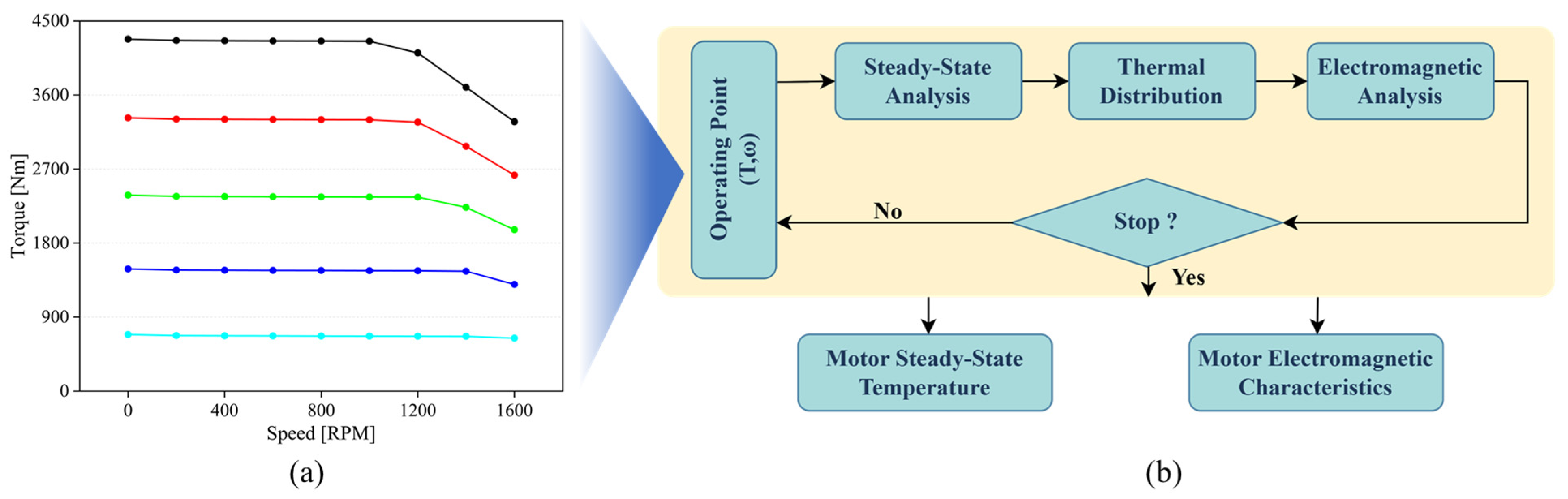
A combined multiphysics design of the propulsion motor for the F-EBP car ferry using an RBSS is proposed considering electromagnetic and thermal performances. Through electromagnetic design, possible heat sources are identified, and thermal behavior under steady state (hot spot points) operation is confirmed.
(v)
Insights on slot insulator selection and the ways to water-seal the propulsion motor are presented.
This article is organized as follows. The concept of F-EBP car ferries using an RBSS and the specifications of the electric propulsion system are described in Section 2. Then, the specification, modeling, loss model, and electromagnetic analysis results of a PMSM are discussed in Section 3, with the losses of the motor converted into a heat source for thermal analysis. In Section 4, an LPTN based on PMSM structure is built and analyzed at a steady state. Finally, Section 5 provides a discussion on the research findings, and the paper is concluded in Section 6.

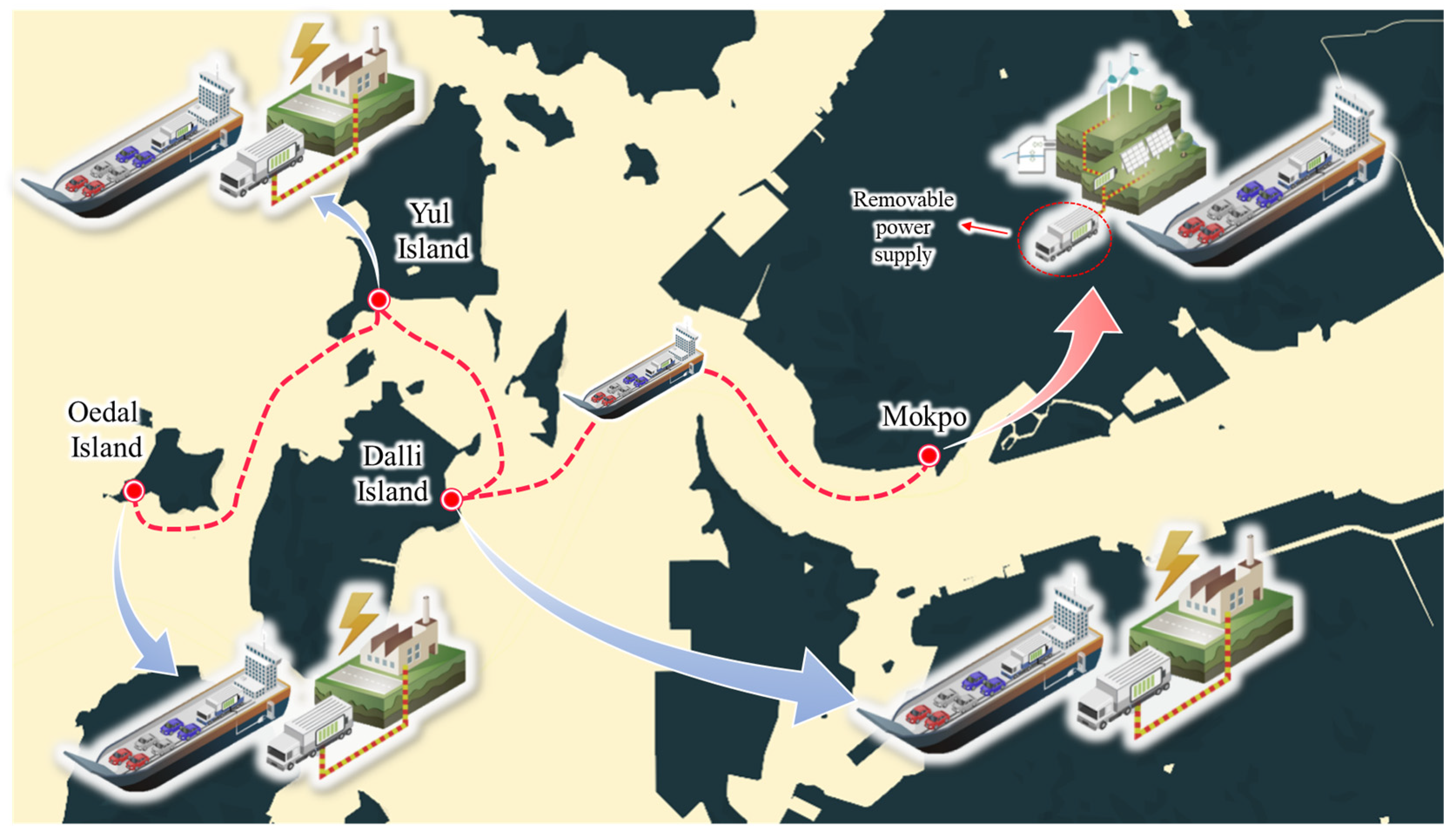
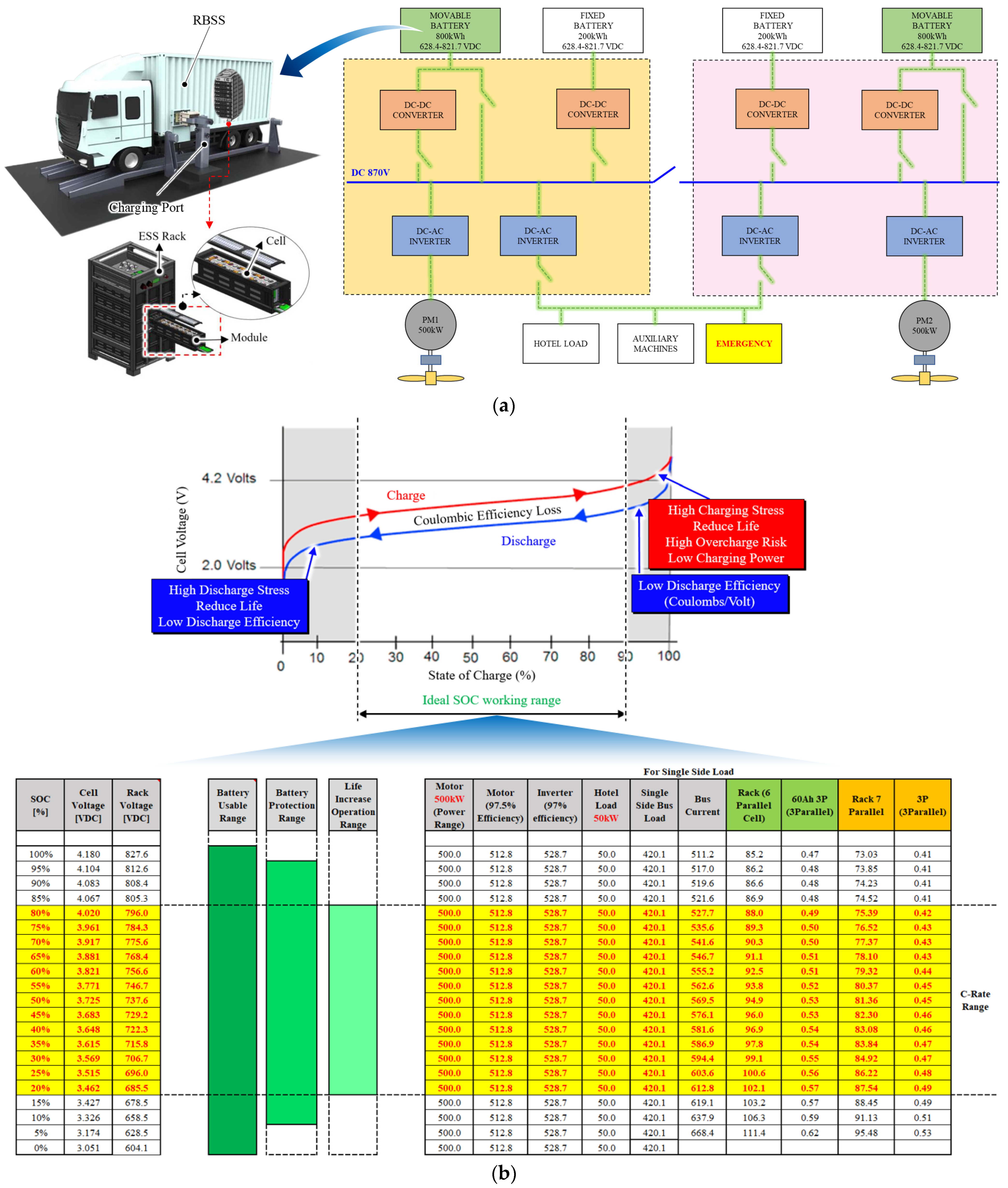
2. Fully Electrified Battery Powered (F-EBP) Car Ferry with Removable Battery Supply Systems (RBSSs)

2.1. F-EBP Car Ferry System Overview

This section focuses on the schematic design concept of the F-EBP car ferries using an RBSS. Since it is a novel idea in the era of changing ship fuels, the concept has not been integrated into the regulations of the classification society or maritime authority yet. Additionally, the car ferry has not been subjected to the regulations of the international classification society, which are strict when applied to fully electrified vessels. Figure 1 illustrates the concept of an F-EBP car ferry powered by an RBSS, which connects islands, for public transportation, operating on designated routes in South Korea. As shown in Figure 1, the car ferry departs from the Mokpo area, makes two stops before ending a one-trip route at Oedal Island, then returns, covers a total distance of 30 km, and takes 1 h for one round-trip. Fully electrified car ferries will be introduced in the Mokpo area, where more than 60% of domestic car ferries are run, to clearly distinguish them from current ships and highlight their environmental friendliness [21]. At each stop station, a roll-on/roll-off-type RBSS that can move by itself is replaced.
The considered F-EBP car ferry has a total length of 60 m and a total weight of 460 gross tonnages. It can transport approximately 100 passengers and more than 20 passenger cars and operate at speeds of up to 10 knots and higher. The F-EBP ferry is shown in Figure 2a. As mentioned above, a roll-on/roll-off-type RBSS is used by the F-EBP car ferry that can move by itself on wheels, as shown in Figure 2a. The design of the F-EBP ferry includes a specified space for safely fastening the roll-on/roll-off-type RBSS. The layout of the ferry is such that the RBSS can be placed in a separate area from the passenger zone, which enhances passenger safety and minimizes the risk of secondary fire damage. Moreover, the propulsion system is designed as an inboard drive which means the electric motor is installed inside the hull of the ship. Two other types of drives for marine applications include the outboard and podded drives that are installed outside of the hull and submerged in the water [15]. The outboard and podded drives are more suitable for small, fast ships and ice-breaking and dynamic-positioning applications, respectively, and thus not considered for the proposed F-EBP car ferry. Inboard drives are suitable for a wide range of ship and vessel types, including pleasure boats, fishing vessels, yachts, and small to medium-sized commercial ships. It is particularly useful for ships that require high maneuverability and a relatively low draft, such as inland waterway vessels and pleasure boats. Therefore, for the proposed F-EBP car ferry, the inboard drive for the propulsion system as shown in Figure 2a is adopted. From Figure 2a, in the inboard drive, the motor is connected to the propeller using a long shaft, which passes through the hull of the ship. Thus, there is a chance of potential water leakage. In the following section, the method to seal the inboard electric drive including the motor is discussed.

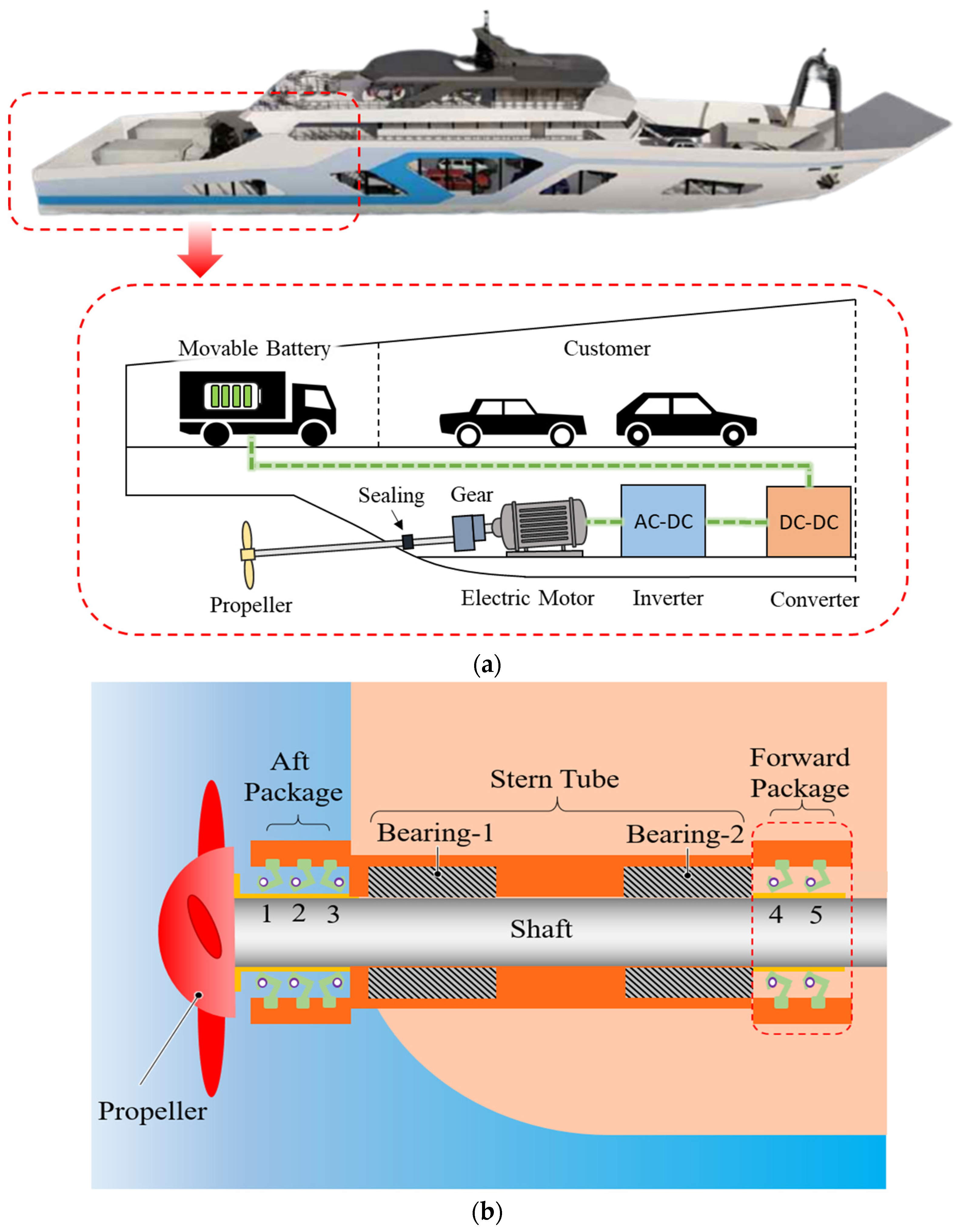
2.2. Sealing Method of Inboard Electric Drives

The shaft connecting the propulsion motor to the ship propeller needs to penetrate through the bottom of the ship hull and should have enough freedom to rotate properly to create the required thrust. For an inboard drive as shown in Figure 2, stuffing boxes, face seals, and lip seals are the three basic sealing techniques generally used to restrict any water leakage. They are all made up of two primary parts. First, there is a short-length specialized hose that fits over the metal tube welded to the hull of the ship, connecting the propulsion chamber and the outside of the ship, called a stern tube, and, second, there is a seal that fits around the shaft and attaches to the hose. For the proposed system as shown in Figure 2b, a lip-seal-based sealing mechanism is used. From Figure 2b, seal 1 directly faces the water side and works as a dirt excluder. This outermost seal is rapidly worn out; hence, to prevent any leakage, seal 2 is also placed outside the hull. Seals 3 and 4 face seals with oil in the header tank, hence lubricating the stern tube shown in Figure 2b. Finally, seal 5 prevents the leakage of the lubricant into the propulsion chamber.

2.3. Energy Flow Diagram of F-EBP Car Ferry Propulsion System

The single-line energy flow diagram of the F-EBP car ferry using an RBSS is presented in Figure 3a. The propulsion system is powered by a combination of an RBSS with Li-ion movable batteries with a capacity of 2 × 800 kWh and fixed batteries with a capacity of 2 × 200 kWh [22]. The movable batteries also are implemented for future capacity extension and can charge from 628.5 VDC to 821.7 VDC depending on the state of charge. The RBSS is designed in the form of a small truck with energy storage system (ESS) racks placed as truck load, as shown in Figure 3. The RBSS also includes a charging port to recharge the ESS. A DC-DC converter is used to maintain a constant DC grid to which the air-cooled-type DC-AC inverters are connected. The electric system is responsible for supplying power to various loads, including the main propulsion motor, hotel load, auxiliary machines, and the emergency backup system. The hotel load refers to the power needed for passenger purposes, while the auxiliary machines support the main propulsion and electrical systems. The emergency electric system serves as a backup to provide power to essential systems and equipment in the case of a power failure or emergency. The DC grid supplies 1 MW power divided into two PMSMs, which is the main load of the electric propulsion system and transforms electric energy into the mechanical energy of the propellers. DC links voltage to the inverter; hence, the terminal voltage of the propulsion motor is directly related to the voltage available at the DC grid. Furthermore, the voltage level at the DC grid is affected by the C-rate of the RBSS. C-rate can be defined as the rate at which an ESS cell is charged or discharged relative to its capacity. It is the charge or discharge current in Amps divided by the cell capacity in ampere-hours. The C-rate can be applied to compare batteries of different sizes and types. A C-rate of 1 corresponds to completely discharging the battery from a state of charge (SOC) of 100% to 0% in one hour. Figure 3b shows the relation between cell voltage and the SOC for the Li-ion battery rack. As shown in Figure 3b, the ideal working range of the SOC lies between 20 and 90%. Beyond this range, the battery will suffer high stress, and the life will be reduced. Thus to increase the life of the RBSS, the SOC range is selected between 20 and 80%. As shown in Figure 3b, for the proposed RBSS, the rack voltage at 100% is 827.6. The operation range of the RBSS is highlighted in yellow with rack voltage varying between 685.5 and 796 V. Figure 3b also shows the process to decide the C-rate. Considering a propulsion motor power of 500 kW (frequent operating power of 350 kW, i.e., 70% of full power rating) operating at 97.5% efficiency, hotel of 50 kW, and power converter efficiency of 97%, within the 20–80% SOC range, the C-rate obtained is approximately equal to 0.5 C. For the proposed RBSS, a C-rate of 0.5 C is selected considering the air-cooled battery packs.
The next step for the propulsion system is the selection of the driving architecture between the propulsion motor and the propeller. Among the two options, i.e., a direct drive and a geared drive, a geared drive is selected. Figure 4 shows the energy flow among different parts of the geared drive propulsion system, showing the conversion of electrical energy to mechanical energy. Figure 4 also shows the relations among the C-rate, the current rating of the propulsion motor, and the gear ratio. If instead of a geared drive, the direct drive option is adopted, it will result in a large propulsion motor with a large current rating to maintain a C-rate of 0.5 compared to that of a geared drive. A large propulsion motor with a larger current rating will need better cooling and can violate the space constraint. Therefore, to maintain a C-rate of 0.5 C with air cooling, a geared drive with a gear ratio of 4:1 is selected. The DC-bus voltage rating for the propulsion motor is selected as 728 VDC (approximately 50% SOC). In the following sections, the detailed design process of the propulsion motor considering electromagnetic and thermal performance is presented.

3. Electromagnetic Design and Analysis of Propulsion Motor for F-EBP Car Ferry Propulsion System

3.1. Motor Topology Selection

As shown in Figure 3b, to maintain a C-rate of 0.5 C, the efficiency of the propulsion motor is expected to be higher than 97%. Therefore, it is essential to select a motor topology that can ensure high efficiency. Furthermore, motors for ship propulsion are designed to operate most efficiently at relatively low speeds. At higher speeds, the resistance and drag of the water increase exponentially, requiring a significant increase in power to maintain the same speed. As a result, the power required to propel a ship at high speeds becomes prohibitively expensive and inefficient. Based on the above requirements, PMSMs can be used as propulsion motors considering their high efficiency, high power density, and fast dynamic response. Typically, PMSMs for propulsion application can be categorized into surface permanent magnets (SPMSMs) and interior permanent magnet synchronous motors (IPMSMs). In electrical performance, IPMSMs are known to have higher power density because of their superior magnetic flux density and better magnetic circuit design. A better magnetic circuit design means that the magnetic circuit has been optimized to achieve specific performance goals, such as increased efficiency, reduced losses, higher power density, or improved stability, while in terms of mechanical design, SPMSMs have a simpler structure and are easier to manufacture. Meanwhile, for thermal performance, IPMSMs show better heat dissipation because of the embedded magnets, resulting in a lower temperature rise than SPMSMs. In a ship propulsion application, where the propulsion motor is continuously running at high power, thermal performance is critical to ensure that the motor operates reliably and has an extended lifespan. Moreover, the limitation of space constrained by the priority for passengers and passenger cars demands a propulsion motor with high power density. Considering the aforementioned system level requirements and advantages of thermal effect on PMs, the IPMSM is chosen as the propulsion motor for the F-EBP car ferry. As shown in Figure 3a, the F-EBP car ferry requires two propulsion motors with a rated power of 500 kW and a frequent operating power of 350 kW. The frequent operating power rating is selected considering the life operation power rating of diesel-engine generators (DGs). In DGs, after thirty years of operation, the power rating is expected to reduce by 20–30%. Therefore, in the F-EBP car ferry, the frequent operating power rating is also kept at 70% of the rated power rating.
The design specifications of the IPMSM are presented in Table 1. For the slot–pole combination, a V-shape embedded PM rotor with a 45-slot and 6-pole topology is considered, as shown in Figure 5a. For the PM rotor, a NdFeB rare earth PM with UH grade is utilized due to its high magnetic strength, 1.11 T at the operating temperature of 120 °C, and relative permeability of 1.05. In addition, POSCO steel, which has a lamination thickness of 0.35 mm, a mass density of 7600, and a magnetic flux density of 1.6 T at 4 kA/m, is selected as the core material used for the stator and rotor.

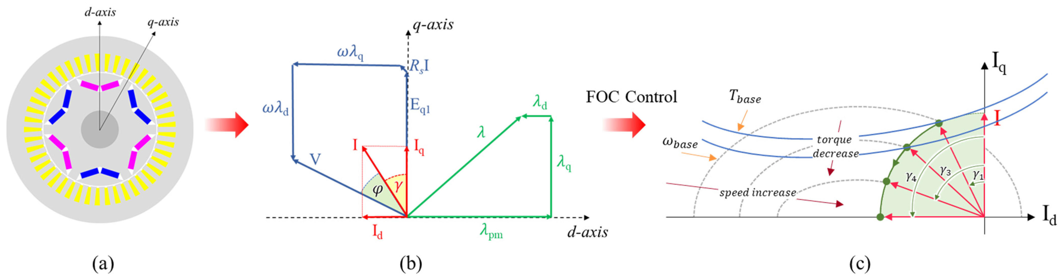
3.2. Electromagnetic Modeling of IPMSM for F-EBP Car Ferry Propulsion

Normally, the operation of an IPMSM is represented in direct, d, and quadrature, q, axes as shown in Figure 5a. The d axis is represented as the axis with the lowest reluctance; meanwhile, the q axis is represented as the highest reluctance path of magnetic flux. The vector diagram of the dq reference frame represents the relation between the flux linkages produced by the PM and the electric loadings with the dq axes. The second quadrant shows the relation between the no-load and on-load voltages and the variation of the current and voltage angles as shown in Figure 5b. The electromagnetic torque and voltage equations for an IPMSM in the dq reference frame can be expressed as
T e = m 2 p ( λ d I q λ q I d )
V = V d 2 + V q 2
[ V d V q ] = R s [ I d I q ] + ω [ λ q λ d ]
where T e is the electromagnetic torque, m is the number of phases, p is the number of pole pairs, I d , q are the direct and quadrature components of the peak phase current, V is the peak phase voltage, ω is the rotation speed, and λ d , q are the dq axes’ flux linkages.
The power factor of the IPMSM can be described as
cos φ = cos ( cos 1 V q V γ )  
In this proposed work, the electromagnetic analysis of the IPMSM will be performed using the field-oriented control (FOC) method. The FOC is a control strategy that determines the performance of an IPMSM by controlling the supply current amplitude and phase angle, which are referred to as the current angle in the q-axis [23]. The optimal values of current amplitude I and phase angle γ can be determined using the maximum torque per ampere (MTPA) operation of an IPMSM, which results in the highest torque output. In an IPMSM, unlike in synchronous motors, the excitation field cannot be directly controlled since it is produced by the PMs. However, during high-speed operations, the back electromotive force (EMF) can exceed the voltage limit of the IPMSM. To overcome this limitation, the FOC method can increase the current angle, γ, beyond the MTPA point to increase the d-axis component of the current and flux. This process, called flux weakening (FW), weakens the flux linkage of the PM and reduces the back EMF. Figure 5c illustrates the concept of the FW method in an IPMSM.

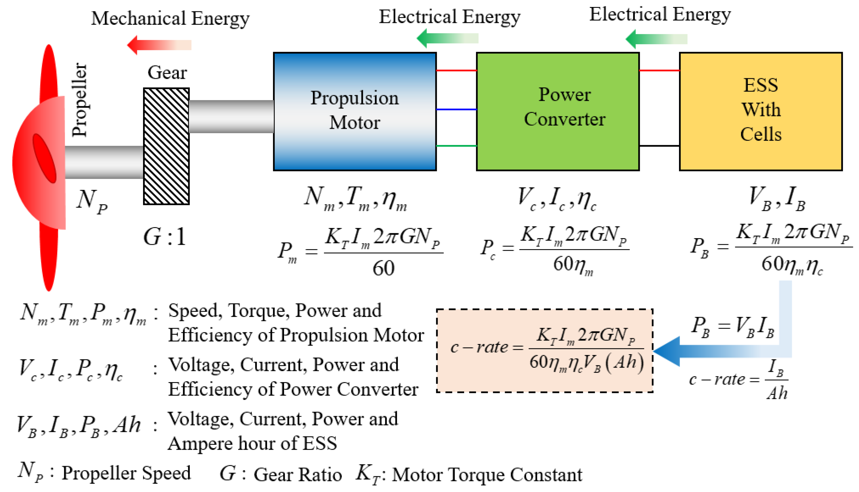
3.3. Loss Models of IPMSM Considering Electromagnetic and Mechanical Losses

Loss analysis plays a crucial role in both the electromagnetic and thermal analysis of electrical machines. In electromagnetic analysis, loss analysis helps in determining the efficiency and performance of the machine by analyzing the losses incurred due to various factors such as resistive losses, eddy-current losses, hysteresis losses, and more. In thermal analysis, loss analysis is used to determine the heat generated due to the losses incurred in the machine. Accurate loss analysis is crucial for predicting the temperature rise in different components of the machine, which can be used to determine the insulation system required for the machine.
There are two types of losses in an IPMSM: electromagnetic and mechanical losses. The total electromagnetic losses of an IPMSM consist of copper loss, iron loss, and eddy-current loss in the PM. The copper loss in a three-phase IPMSM can be defined as a part of the total electrical loss.
P C u = 3 R s I n 2 = 3 2 R s ( I d 2 + I q 2 )
where I n is the root mean square (RMS) of phase current, and the amplitude 2 I n of the phase current can be expressed as I d 2 + I q 2 .
Iron loss in a motor can be divided into three main components: static hysteresis loss, classical eddy-current loss, and excess loss. Static hysteresis loss occurs due to the magnetization and demagnetization of the iron core of the motor, resulting in energy loss in the form of heat. Classical eddy-current loss occurs due to the induction of electric currents in the iron core, which creates a magnetic field that opposes the original magnetic field and results in energy loss. Excess loss occurs due to the interaction between the static hysteresis loss and the classical eddy-current loss, resulting in further energy loss. The magnetization and demagnetization of the iron core during the hysteresis process cause eddy currents to be induced in the iron core, which in turn cause further magnetization and demagnetization. This creates a feedback loop that amplifies the energy loss and results in excess loss. The iron losses in a stator and rotor of an IPMSM can be calculated by analyzing the magnetic flux density distribution and its variation waveform using the 2D-FEM. The iron loss per unit volume P F e can be calculated as follows [24]:
P F e = P h + P c + P e = k h f B m 2 + k c ( f B m ) 2 + k e ( f B m ) 1.5
where k h , k c , k e are the loss coefficient and can be obtained from manufactured data, B m is the peak of the magnetic flux density, and f is frequency.
The eddy-current loss can occur in PMs because of variations in the magnetic field caused by changes in magnetization or external magnetic fields, resulting in the generation of electric currents in the magnets, which can lead to energy dissipation in the form of heat. According to [25], Joule’s law can be used to calculate the magnet eddy-current loss as in the following equation:
P e d d y = l a j Ω e Ω e , j J e 2 σ d Ω
where l a is the axial length of magnets, Ω e is the magnetic potential scalar of the element whose index number is j, and J e is the harmonic eddy-current density.
The mechanical loss, which includes the friction and windage losses, is estimated and is proportional to the rotating speed of the motor [26]:
P m = P m r a t e d ( n n r a t e d ) 2
where P m r a t e d is mechanical loss at rated speed and is approximately 0.1% of rated power, n is the speed of the motor at the operating point, and n r a t e d is the rated speed of the motor. In this proposed motor, the rated motor speed is 1200 rpm.

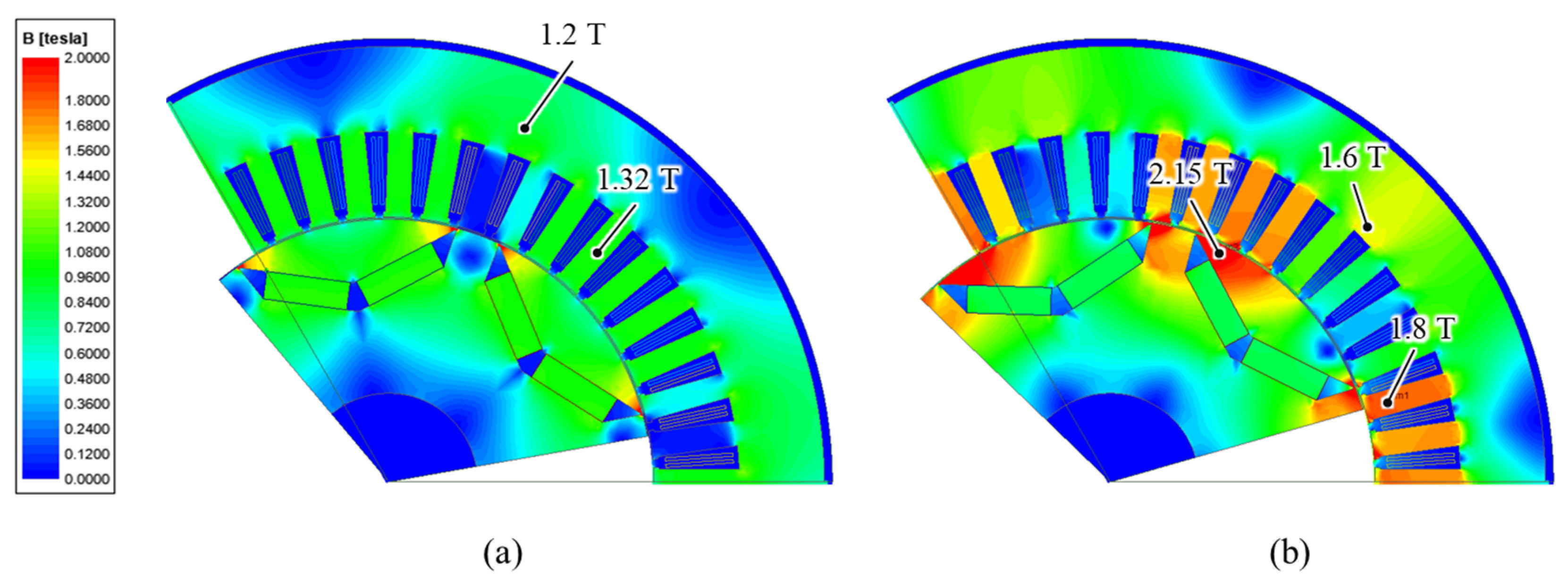
3.4. Electromagnetic Design Results

The electromagnetic analysis of the IPMSM is implemented by 2D-FEA [27]. The flux density distribution at no-load with 20 °C and at on-load with 120 °C of the PM is shown in Figure 6a,b. The saturated level of lamination electrical steel is 1.8 T, and hence the flux density in stator teeth and yoke at on-load analysis stays below the saturation limit of 2.0 T for POSCO steel. The flux density of stator teeth and stator yoke is 1.8 T and 1.6 T, within an acceptable range as shown in Figure 6b. It should be noted that the electromagnetic performance is checked at 1200 rpm. The other factors of the electromagnetic performance at the rated speed of 1200 rpm are listed in Table 2. The torque is calculated by using Equation (5), where flux linkages λ d ,   λ q are obtained from 2D FEA. The output power, as well as shaft power, is calculated by
P o = T e ω P F e P e d d y P m e c h
where P F e , P e d d y , P m e c h   are iron loss, eddy-current loss in the PM, and mechanical loss in Equations (6)–(8). The efficiency is defined as the ratio between output power and input power and is described as
η = P o P i = P o T e ω + P c u
where P c u is copper loss, calculated by using Equation (5). The power factor is obtained from Equation (4). Table 2 also shows the loss component of the IPMSM, where the copper loss in winding is dominant, accounts for 83% of the total loss. The eddy-current loss in the PM is insignificant compared to other loss components and can be neglected in thermal analysis. The losses mentioned in Table 2 will act as the heat source for the IPMSM in the thermal analysis mentioned in the later sections.
Figure 7 shows the efficiency maps for the proposed IPMSM at a 120 °C winding temperature and 80 °C PM temperature. To obtain the efficiency map of the IPMSM motor, several points on the torque–speed curve are required. At each operating point, the input power, output power, and losses (copper losses, core losses, PM losses, and mechanical losses) are calculated. The efficiency is then calculated as the ratio of output power to input power, and this value is plotted on the efficiency map at the corresponding torque–speed point. By repeating this process for multiple operating points, an efficiency map can be generated that shows the efficiency at various torque and speed combinations. Furthermore, to check the frequent operation point of the F-EBP car ferry propulsion system over the whole efficiency region shown in Figure 7, propeller curve data are obtained and traced over the efficiency map. The propeller curve is obtained from hydrodynamic model analysis and by extending the value obtained through the water tank experiment by manufacturing a miniature electric propulsion driveway with Robinson’s curve [28]. As can be observed from Figure 7, the operating point of the propeller load curve is in the high-efficiency region of the proposed IPMSM.

4. Thermal Design and Analysis Results of Propulsion Motor for F-EBP Car Ferry Propulsion System

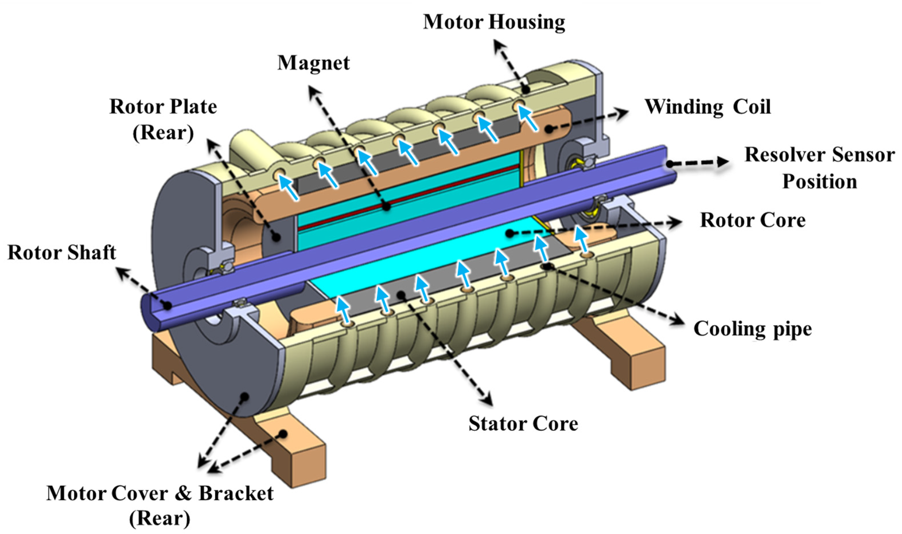
4.1. Overview of Cooling System of Propulsion Motor for F-EBP Car Ferry Propulsion System

Figure 8 illustrates the 3D model of the proposed IPMSM. From Figure 8, the electromagnetic parts mentioned in the previous section are placed within a housing and sealed from either side by the front and rear cover with holes for the rotor shaft. The whole assembly is placed over brackets. The housing contains spiral channels acting as cooling channels through which coolant flows to cool the IPMSM. The coolant flow rate is determined as 50 L/min, flowing through the cooling channel around the housing with a temperature of 26 °C. Table 3 shows detailed information on the coolant of the propulsion motor. In the following section, the thermal analysis of the proposed IPMSM is presented.
Ship propulsion motors typically operate in harsh and challenging environments, including chances of exposure to moisture, saltwater, and vibrations. As a result, stator winding insulation for ship propulsion motors needs to be able to withstand these conditions. One common type of winding insulation used in ship propulsion motors is epoxy mica insulation. This insulation is made by impregnating mica paper with an epoxy resin, which provides excellent resistance to moisture, heat, and chemicals. Another type of insulation used in ship propulsion motors is glass-reinforced epoxy insulation. This insulation is made by impregnating a glass cloth with an epoxy resin and then applying it to the stator windings. Glass-reinforced epoxy insulation is also highly resistant to moisture, heat, and chemicals. In addition to these types of insulation, ship propulsion motors may also use special coatings and treatments to protect the stator windings from moisture and corrosion. For example, some motors are coated with a varnish or epoxy coating to provide additional protection. For the proposed motor, epoxy mica insulation is considered. Moreover, the slot liner uses Nomex as insulating material. Thermal characteristics of the insulating materials will be discussed in the following sections.

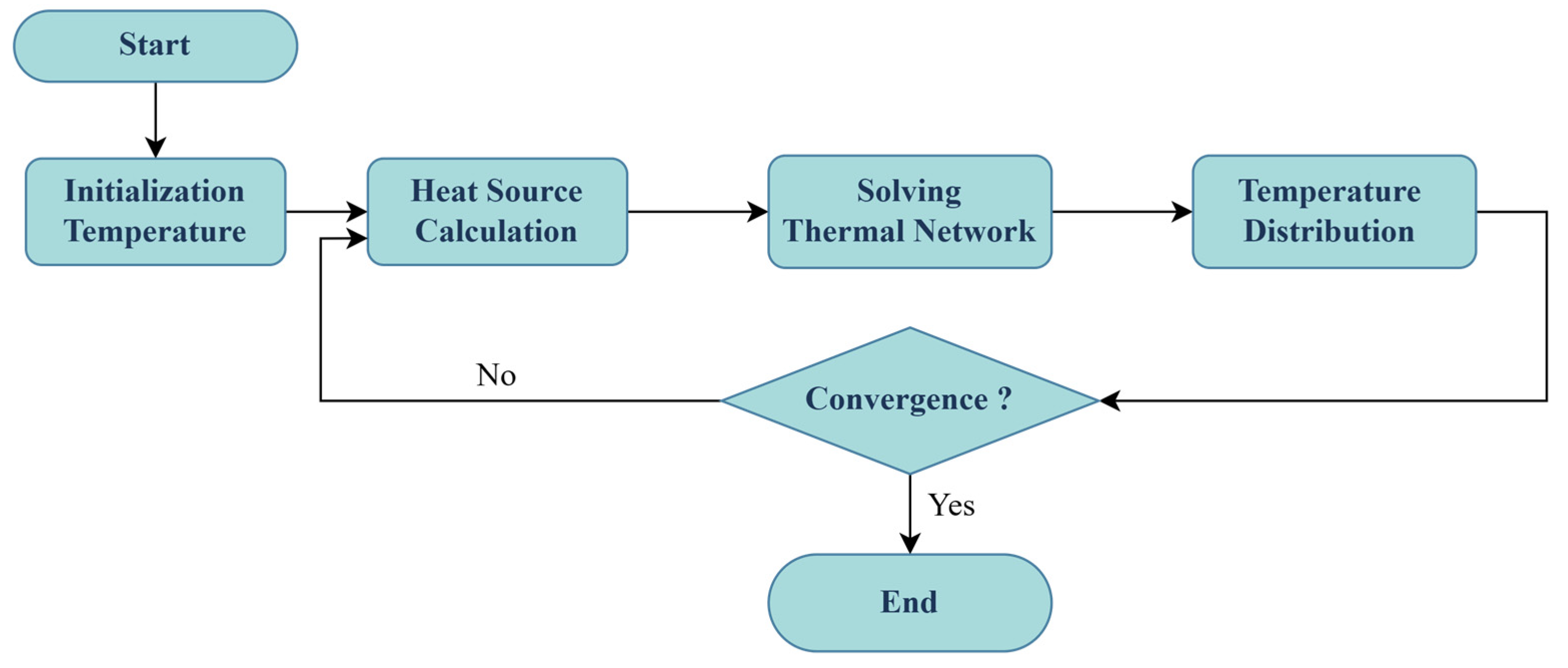
4.2. Lumped-Parameter Thermal Network (LPTN) Model of Proposed IPMSM

To analyze the thermal characteristics of the IPMSM, the thermal analysis was conducted using the LPTN model as shown in Figure 9. As shown in Figure 9, the thermal network of the motor can be described as a combination of a heat source and thermal resistances. The heat source is generated from losses such as copper loss, core loss, PM loss, and mechanical loss. The thermal resistances such as conduction, convection, and contact resistances are calculated in the following section. The radiation resistance is omitted for simplified calculation.
The conduction thermal resistance R c depends on the path length L , surface area A , and thermal conductivity k and is described as
R c = L k A  
The convection resistance R c v is described as
R c v = 1 h c v A  
where h c v is convection heat transfer across the airgap and ducts in the housing.
h c v = N u × k 2 × L
where
N u = f 8 · ( R e 1000 ) · P r 1 + 12.7 · ( f / 8 ) 0.5 ( P r 2 / 3 1 )
P r = c p μ k
R e = ρ v L μ
where N u is the Nusselt number, P r is the Prandtle number, v is the fluid velocity (m/s), c p is the fluid specific heat capacity (kJ/(kg.°C)), μ is fluid dynamic viscosity (kg/m/s), and f is the friction factor [29]. Table 4 provides information on the thermal properties used to calculate the thermal resistance of the LTPN using Equations (11)–(16). Table 4 also shows the thermal properties of the slot, including copper winding, winding insulation, and slot liner.
The accuracy of the thermal networks used in predicting the thermal performance of electrical motors is dependent on several parameters, such as the interface gap between components, the thermal conductivity of the materials used, and the estimation of thermal contact resistances [30,31]. The values for these parameters may be difficult to obtain, and assumptions need to be made in some cases. For example, the thermal conductivity of electrical steel is assumed to contain 1.5% silicon in this thermal analysis. The interface gap between aluminum and aluminum is in the range of 0.0005 to 0.0025 mm, while the gap between aluminum and iron is in the range of 0.0006 to 0.006 mm [32]. The gap between the stator lamination and housing is also important, and it is a function of the roughness of the laminated outer surface. In this study, a gap value of 0.001 mm is used between the lamination and aluminum housing considering the roughness of the lamination.
Another crucial component of the thermal network is the heat source. As mentioned before, the loss in electromagnetic analysis is the heat source in thermal analysis. Copper loss in winding is dependent on the temperature because of the effect of temperature on copper resistivity, which leads winding resistance to be dependent on temperature:
R s T = R s 20 ( 1 + α Δ T )
where R s T ,   R s 20 are the winding resistance at temperature T °C and 20 °C, respectively. α is the temperature coefficient of resistivity, with the given value of 0.00393, and Δ T is temperature rise with 20 °C of ambient temperature. The other losses, such as iron loss, the eddy-current loss of the PM, and mechanical loss, are assumed independent from temperature.

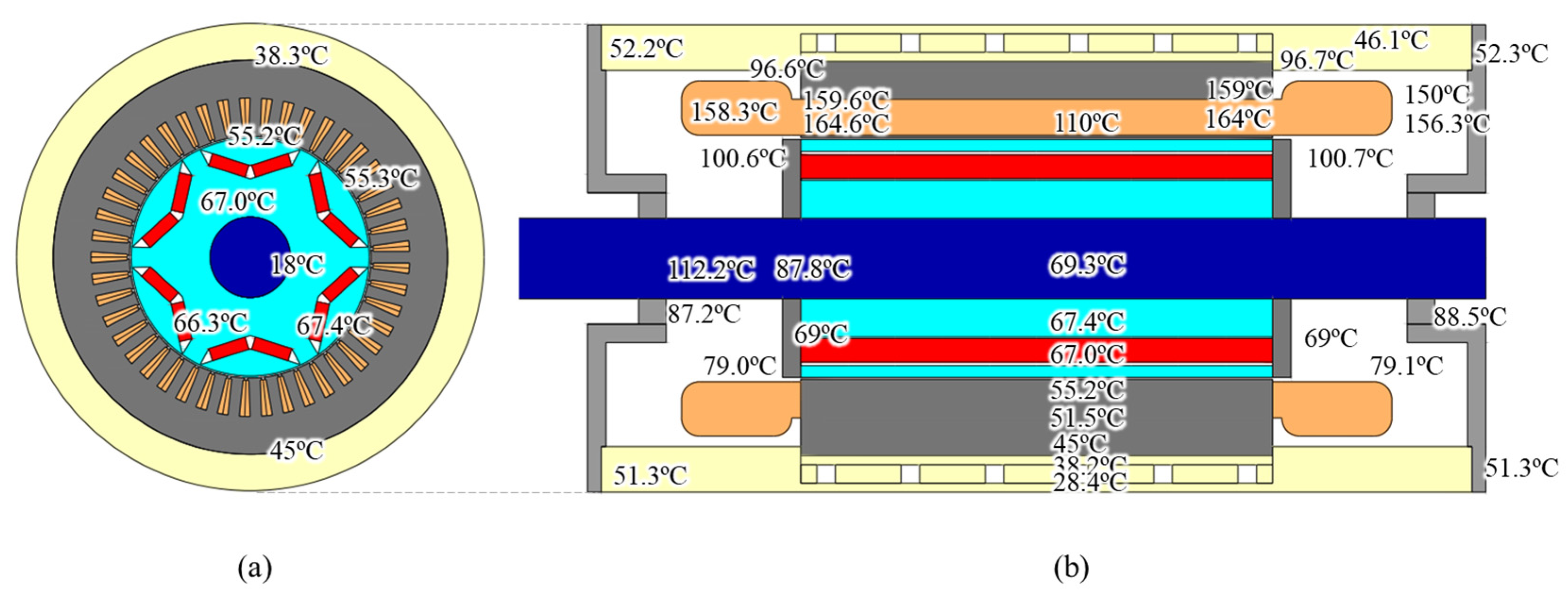
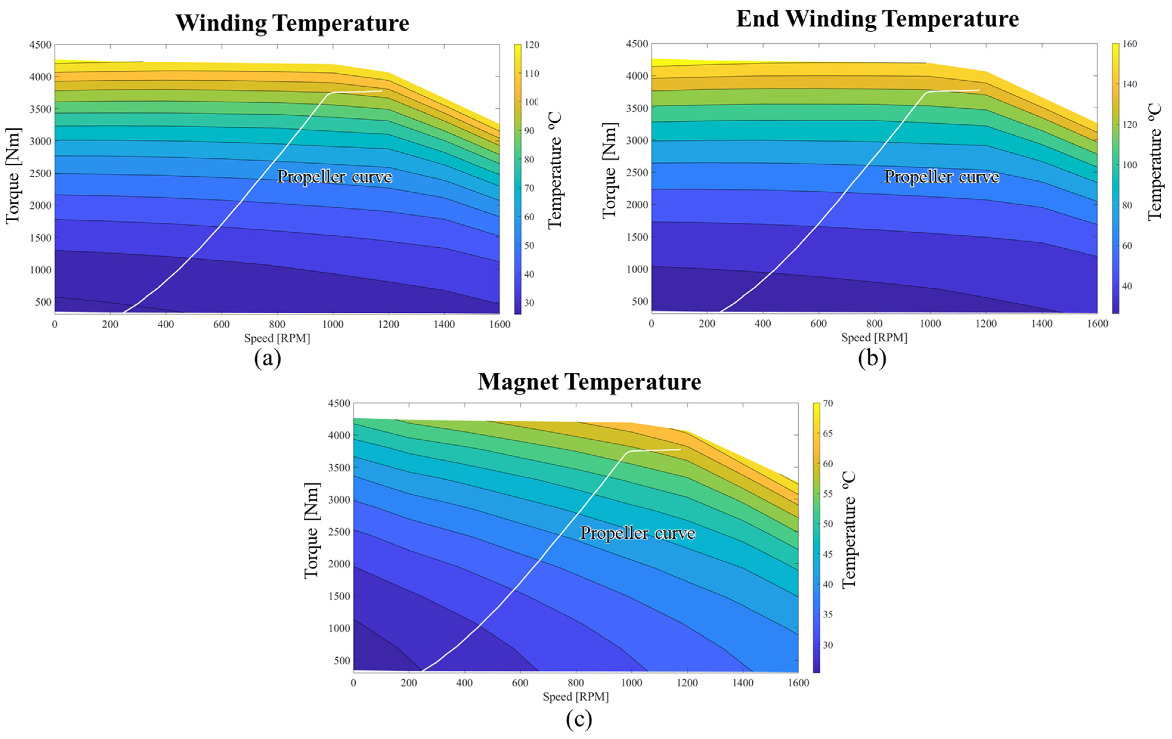
4.3. Steady-State Thermal Analysis

For steady-state thermal analysis, the thermal temperature rise ΔT of each node of the lumped-parameter thermal network is calculated as shown below:
G · Δ T = P
[ G 1 , 1 G 1 , 2 G 1 , i G 1 , n G 2 , 1 G 2 , 2 G 2 , i G 2 , n G i , 1 G i , 2 G i , i G i , n G n , 1 G n , 2 G n , i G n , n ] [ Δ T 1 Δ T 2 Δ T i Δ T n ] = [ P 1 P 2 P i P n ]
G i , i = G i j = 1 , j i n G i , j
G i , j = 1 i , j
where G i , j indicates the thermal conductance between nodes i and nodes j, and G i is the thermal conductance between nodes i and ambient. The thermal conductance G i , j is reverse with thermal resistance i , j , which includes the effect of conduction and convection and can be calculated following Equations (11)–(16). G is the thermal conductance matrix, and P is heat sources given to the nodes.
Figure 10 presents the steady-state thermal network analysis process. First, the initial temperatures of motor components such as the winding, PM, shaft, and bearing are set to be 20 °C. Second, the electromagnetic loss, particularly copper loss, is calculated by 2D-FEM and converted into heat sources in thermal analysis. Third, the thermal temperature rise Δ T is obtained by solving the thermal network using Equation (17), and the distribution of the temperature of the IPMSM is acquired. The process is repeated until the convergence rate and the temperature difference in percentage are less than 0.5%.
Figure 11 shows the average temperature of the motor component and corresponding loss variation with iteration following the steady-state analysis process. As we can observe, the temperature change of each iteration corresponds to the loss. In the first iteration, the initial temperature is 20 °C, and therefore the copper loss calculated by 2D-FEM is minimum, which agrees well with Equation (17). With the update of temperature, the result reaches a steady state after three iterations. Moreover, an illustration of the thermal distribution of the motor at final iteration is shown in Figure 12, which represents the radial and axial temperature distribution at the steady state.
The highest temperature region is found on the stator side, because of the dominance of copper loss in the winding. This is because the heat generated by the copper loss is not effectively dissipated, as there is no cooling structure in the slot. The poor thermal conductivity of air in the airgap also contributes to the high temperature. Additionally, the long distance between the winding and the stator core results in a hot spot at the end of the winding, with a temperature of up to 165 °C.
The NdFeB permanent magnet utilized in the IPMSM has a maximum allowed temperature of 180 °C. The performance of the magnet decreases as the temperature increases, and its characteristics can be lost because of irreversible demagnetization if it operates below the knee point. The knee point refers to the temperature at which the magnetic properties of the PMs start to deteriorate rapidly. At this point, the reduction in magnetic properties becomes more severe and continues to worsen with further temperature increases. This can result in a decrease in motor performance due to the weakening of the PM strength. However, Figure 12 indicates that the steady-state temperature of the permanent magnet is 67 °C, which is well within the safe thermal range. This suggests that the reduction in magnetic properties at this temperature should have minimal impact on the performance of the motor.

4.4. Coupled Electromagnetic-Thermal Analysis

In order to comprehensively analyze the results of the electromagnetic and thermal analysis of the proposed IPMSM, it is necessary to investigate the performance at various operating points while considering its temperature distribution at a steady state. The illustration of the coupled electromagnetic-thermal analysis is presented in Figure 13. The first step involves defining an operating point for the motor based on a combination of torque requirements and speed, as depicted in Figure 13a. Next, a steady-state analysis is performed according to Section 4.3 to obtain the temperature of the motor components such as the winding, end winding, PM, shaft, and bearing. After updating the temperature of the motor component, an electromagnetic analysis is conducted to obtain the characteristics of the IPMSM. This process is repeated until all operating points are analyzed and convergence is achieved. Finally, the steady-state motor temperature and electromagnetic characteristics are stored, as shown in Figure 13b.
As previously discussed in Section 3.4, the initial efficiency map of the motor was obtained at fixed winding and PM temperatures of 120 °C and 80 °C, respectively. To obtain a more detailed efficiency map, a coupled electromagnetic-thermal analysis was used, and the results are presented in Figure 14. Figure 7 is also included in Figure 14a for the purpose of comparing the two efficiency maps. As shown in Figure 14a, the operating point of the propeller load curve falls within the high-efficiency region of the proposed IPMSM. However, in Figure 14b, the operating point of the propeller load curve falls within a lower high-efficiency region due to increasing loss with temperature. Consequently, the region of the highest efficiency in the intense efficiency map is narrower compared to Figure 14a, and the maximum torque available is reduced, leading to a decrease in the overload ability of the proposed IPMSM.
Additionally, the steady-state temperatures of the winding, end winding, and PM are shown in Figure 15. It is observed that the maximum temperature of the winding and end winding is 120 °C and 160 °C, respectively, and the peak temperature occurs in the maximum torque and current region, as shown in Figure 15a,b. This confirms the durability of the winding when operating under continuous working conditions. Furthermore, Figure 15c shows the maximum steady-state temperature of the PM, which is 70 °C, still within the safe operating range for PMs. It should be noted that the highest temperature of the PM occurs in the high-speed region.

5. Comparison with Available Technologies and Discussion on Future Challenges and Room for Improvement

This section aims to provide a comparison of the proposed F-EBP vessel using an RBSS with other commercially available technologies. Different power system configurations are shown in Table 5. The power system configurations are either hybrid-electric (batteries along with a diesel engine/generator or fuel cell) or purely electric (fixed or removable battery). The power source capacity is divided into three types based on power system configuration, generator/engine (G/E), fuel cell (FC), and battery supply system (BSS). Similarly, the DC bus voltage, number of passengers/cars, and speed in knots are provided. Finally, the capacity of motor use for the propulsion system is provided.
In Table 5, the most recent ship (2019) is Ellen from Denmark with a capacity of 200 passengers, similar to the capacity of 100 passengers and 20 cars of the proposed ship. However, the battery is three times larger because of the double ship speed. Another purely electric ship, MF Ampere, requires a 1040 kWh battery system for double passenger/car capacity with the same ship speed. However, MF Ampere covers a shorter distance, up to 6 km in 20 min [37], compared to the 30 km in 1 h of the proposed ship. In addition, the hybrid-electric propulsion ‘Vision of the Fjords’ has a total capacity of 2074 kW and 600 kWh compared to the 1800 kWh of the purely electric propulsion ‘Future of the Fjords’ with the same passenger capacity of 400 passengers. Furthermore, the ‘Future of the Fjords’ electric system can provide for two motors with 450 kW compared to ‘Vision of the Fjords’ with only two motors with 150 kW. In the motor prospect, the target ship can provide supply power to two motors with 500 kW compared to other types with lower battery capacity, which shows improvement in motor manufacturer design and the efficiency of the system.
After a comparison with other available technologies, the challenges and emerging trends for fully electrified ships need to be discussed [42]:
(i)
There is a requirement for specialized grid stations on the coast to have strong enough charging for ships operating with various kilowatt-hour power depending upon weather conditions.
(ii)
A typical grid station may cost millions of dollars, and hence the economic problem should be considered when building it.
(iii)
Safety is a critical issue due to the high power of the battery/charging system.
(iv)
The capacity of the ship is limited because of the limit on the energy density of the battery, while increasing the number of batteries in a ship is not a practical solution due to size and weight limitations.
The concept of a roll-on/roll-off removable battery supply system can be a solution for the problems posed above:
(i)
The roll-on/roll-off removable system can self-move by its wheel. Therefore, a charging grid station for a battery system is not needed to be built in the coastal area. In addition, the flexibility in building position can help to avoid big tides or typhoons in the coastal area.
(ii)
Due to the limitation of the energy density of the battery, it is inefficient to use batteries to operate the main propulsion engines operating on unspecified routes. Therefore, the car ferry interconnecting islands would yield significant profit with specific routes.
(iii)
The cost investment of the battery system can be reduced due to the removable battery that can be shared. In addition, the mismatch problem between battery replacement life and the operating life of the ship can be solved.
From the above benefits of a roll-on/roll-off removable battery supply system, the limitations of traditional fixed battery power ship propulsion can be solved, and it is expected that, with continuous improvement, this technology can be used in larger marine vessels.
In the future, based on the multiphysics modeling of the IPMSM, a prototype will be manufactured, and the performance will be validated against the simulation results.

6. Conclusions

The concept of a fully electrified battery powered (F-EBP) car ferry using a roll-on/roll-off-type removable battery supply system is discussed. A detailed idea on how to select the system level components such as the battery rating, DC bus, and physical parameters of the propulsion motor is also presented. Considering the requirement for the system, an interior permanent magnet synchronous motor (IPMSM) is investigated. The selection of an IPMSM over a surface permanent magnet synchronous motor (SPMSM) is made by considering higher power density and the advantages of the thermal aspect for the PM. To obtain electromagnetic performance and loss data, electromagnetic simulation is implemented, and a loss model is developed. An electromagnetic analysis is performed by 2D finite-element analysis, and the results show that the motor achieves high efficiency (98.4%) and power factor (88%) at the rated operating point. A thermal network is studied, and the thermal analysis shows that the maximum temperature of coil winding and the permanent magnet are 165 °C and 67 °C, respectively. This signifies that the motor is still working in the safety region and can work in continuous conditions without harm to the motor performance, leading to a long life cycle. The contribution of this work can be summarized in the following take-away points:
(i)
Readers can have an idea of the detailed system level energy flow infrastructure for the F-EBP car ferry. This work will help in deciding the operating range of the system voltage level for the DC grid by selecting the C-rate level.
(ii)
This work offers readers the idea on how to link C-rate level with the propulsion motor and other system components in deciding component level initial physical parameters.
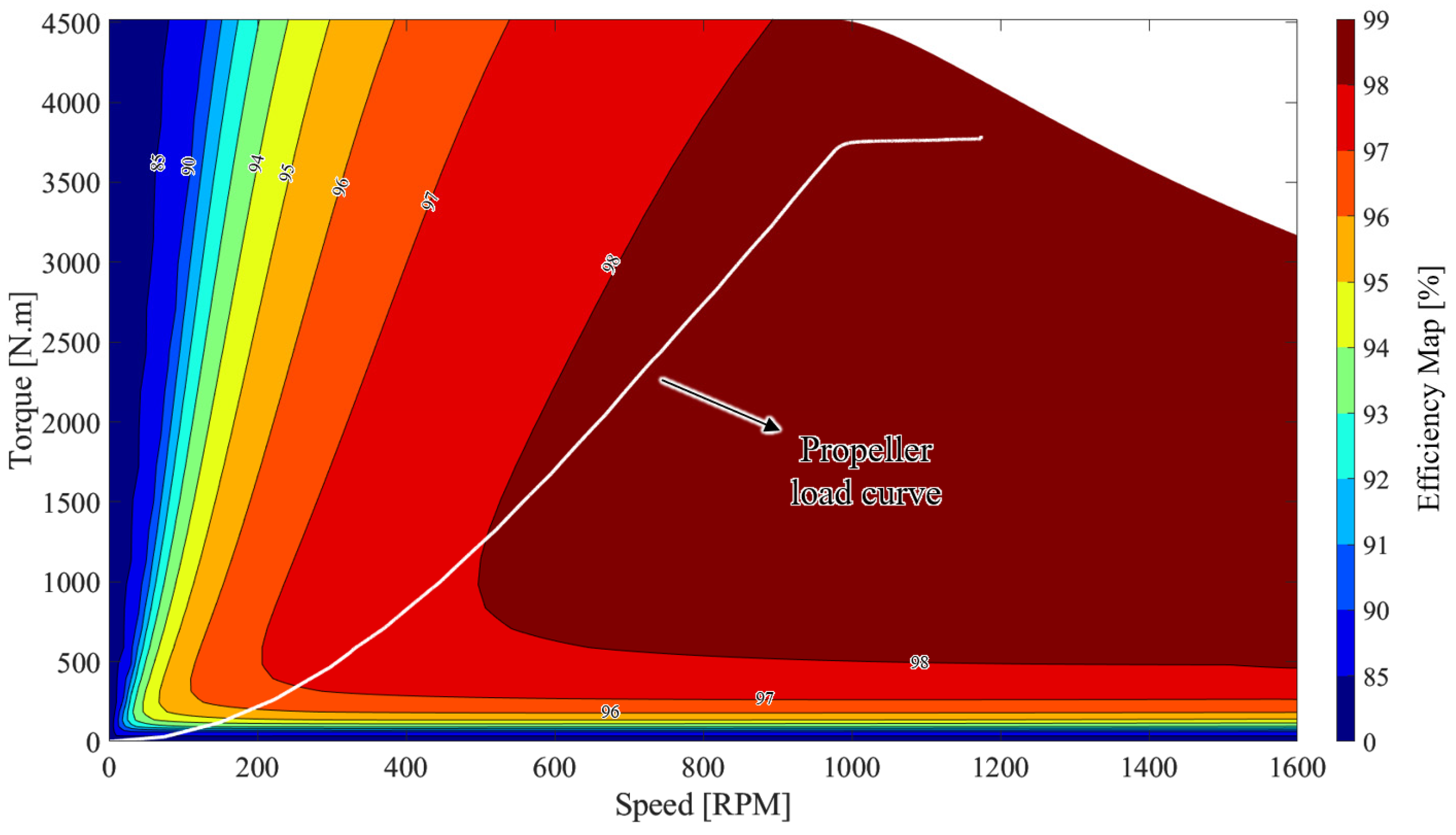
(iii)
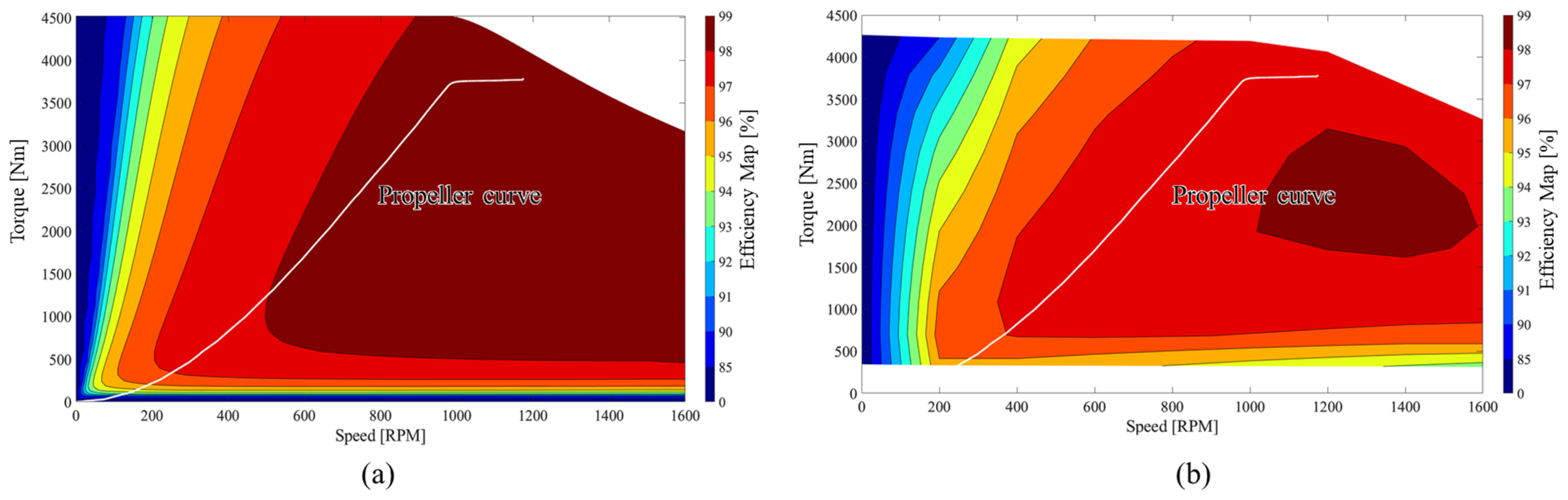
An in-depth multiphysics design of the propulsion motor considering system level requirements is also showcased. The operating curve of the propeller and motor are compared to discuss the efficiency. This information is useful in upgrading the ongoing research on the full electrification of the shipping industry.

Author Contributions

Conceptualization, V.-K.T.; methodology, V.-K.T.; software, J.-H.C. and V.-K.T.; validation, S.P. and J.-H.C.; investigation, V.-K.T.; data curation, J.-W.L. and J.-H.C.; writing—original draft preparation, V.-K.T.; writing—review and editing, S.P.; visualization, V.-K.T.; supervision, Y.-D.C. and P.-W.H.; project administration, J.-H.C. and P.-W.H.; funding acquisition, J.-H.C. and P.-W.H. All authors have read and agreed to the published version of the manuscript.

Funding

This research was funded with the support of the 2021 Ministry of Oceans and Fisheries electric propulsion car ferry and a roll-on/roll-off power supply system development project (R&D project number: 20200469).

Data Availability Statement

No new data were created or analyzed in this study. Data sharing is not applicable to this article.

Conflicts of Interest

The authors declare no conflict of interest.

References

  1. UNCTAD. Review of Maritime Report 2021; UNITED NATIONS: New York, NY, USA, 2021. [Google Scholar]
  2. Polakis, M.; Zachariadis, P.; de Kat, J.O. The Energy Efficiency Design Index (EEDI). In Sustainable Shipping; Springer International Publishing: Cham, Switzerland, 2019; pp. 93–135. [Google Scholar]
  3. IMO. IMO Update: Marine Environment Protection Committee—MEPC 76. Int. Marit. Organ. 2021, 10, 1–5. Available online: https://www.dnv.com/news/imo-update-marine-environment-protection-committee-mepc-76-203128 (accessed on 2 February 2023).
  4. Yang, C. Policies, Regulatory Framework and Enforcement for Air Quality Management: The Case of China-Environment Working Paper No. 157. 2020. Available online: https://www.oecd-ilibrary.org/environment/policies-regulatory-framework-and-enforcement-for-air-quality-management-the-case-of-korea_8f92651b-en (accessed on 2 February 2023).
  5. Tobergte, D.R.; Curtis, S. IGU World LNG Report—2017. J. Chem. Inf. Model. 2017, 53, 1689–1699. Available online: https://www.igu.org/resources/igu-world-lng-report-2017/ (accessed on 19 March 2023).
  6. The Economist. Green Finance for Dirty Ships|The Economist. 2017. Available online: https://www.economist.com/finance-and-economics/2017/03/11/green-finance-for-dirty-ships (accessed on 4 February 2023).
  7. 2016 Environmental Statistics Yearbook. Available online: https://www.keep.go.kr/portal/144?action=read&action-value=f3364998bebc6a71da71a184ecf97829&tags=통계 (accessed on 4 February 2023).
  8. Kolodziejski, M.; Michalska-Pozoga, I. Battery Energy Storage Systems in Ships’ Hybrid/Electric Propulsion Systems. Energies 2023, 16, 1122. [Google Scholar] [CrossRef]
  9. Xu, L.; Guerrero, J.M.; Lashab, A.; Wei, B.; Bazmohammadi, N.; Vasquez, J.C.; Abusorrah, A. A Review of DC Shipboard Microgrids—Part I: Power Architectures, Energy Storage, and Power Converters. IEEE Trans. Power Electron. 2022, 37, 5155–5172. [Google Scholar] [CrossRef]
  10. Sulligoi, G.; Vicenzutti, A.; Menis, R. All-Electric Ship Design: From Electrical Propulsion to Integrated Electrical and Electronic Power Systems. IEEE Trans. Transp. Electrif. 2016, 2, 507–521. [Google Scholar] [CrossRef]
  11. Seung-ho, J. 2018 Annals of Marine Fisheries Statistics-Korean. 2018. Available online: https://www.mof.go.kr/article/view.do?articleKey=23987&boardKey=32&menuKey=396&currentPageNo=1 (accessed on 5 February 2023).
  12. Kirtley, J.L.; Banerjee, A.; Englebretson, S. Motors for Ship Propulsion. Proc. IEEE 2015, 103, 2320–2332. [Google Scholar] [CrossRef]
  13. Hassannia, A.; Darabi, A. Design and performance analysis of superconducting rim-driven synchronous motors for marine propulsion. IEEE Trans. Appl. Supercond. 2014, 24, 2280346. [Google Scholar] [CrossRef]
  14. Banerjee, A.; Tomovich, M.S.; Leeb, S.B.; Kirtley, J.L. Power converter sizing for a switched doubly fed machine propulsion drive. IEEE Trans. Ind. Appl. 2015, 51, 248–258. [Google Scholar] [CrossRef]
  15. Park, J.H.; Lee, T.W.; Jeong, Y.H.; Hong, D.K. Novel Multi-Physics Computational Simulation of a 10 kW Permanent Magnet Motor for Podded Propulsion. Energies 2022, 15, 6607. [Google Scholar] [CrossRef]
  16. Chasiotis, I.D.; Karnavas, Y.L. A generic multi-criteria design approach toward high power density and fault-tolerant low-speed PMSM for pod applications. IEEE Trans. Transp. Electrif. 2019, 5, 356–370. [Google Scholar] [CrossRef]
  17. Bianchi, N.; Bolognani, S.; Ružojčić, B. Design of a 1000 HP Permanent Magnet Synchronous Motor for Ship Propulsion. 2009. Available online: https://ieeexplore.ieee.org/document/5279055 (accessed on 2 February 2023).
  18. Zhang, Z.; Guo, H.; Liu, Y.; Zhang, Q.; Zhu, P.; Iqbal, R. An Improved Sensorless Control Strategy of Ship IPMSM at Full Speed Range. IEEE Access 2019, 7, 178652–178661. [Google Scholar] [CrossRef]
  19. Lee, J.G.; Lim, D.K.; Jung, H.K. Analysis and Design of Interior Permanent Magnet Synchronous Motor Using a Sequential-Stage Magnetic Equivalent Circuit. IEEE Trans. Magn. 2019, 55, 2922043. [Google Scholar] [CrossRef]
  20. Ouldhamrane, H.; Charpentier, J.F.; Khoucha, F.; Zaoui, A.; Achour, Y.; Benbouzid, M. Optimal Design of Axial Flux Permanent Magnet Motors for Ship RIM-Driven Thruster. Mach. Mach. 2022, 10, 932. [Google Scholar] [CrossRef]
  21. Hong, J.P.; Kim, Y.S.; Shim, H.W.; Kang, H.J.; Kim, Y.; Kim, G.B.; Cho, S. Study on a Fully Electrified Car Ferry Design Powered by Removable Battery Systems Considering Domestic Coastal Environment. J. Ocean Eng. Technol. 2021, 35, 1–12. [Google Scholar] [CrossRef]
  22. Choi, J.; Kim, Y.-S.; Hwang, D.; Heo, J.; Lee, J. Electric Propulsion System Design of an Electric-Powered Car Ferry. Korean Electr. Soc. Conf. Proc. 2021, 1291–1292. Available online: https://www.dbpia.co.kr/journal/articleDetail?nodeId=NODE10610177 (accessed on 4 February 2023).
  23. Paul, S.; Chang, J.; Bang, D. Performance of Urban Water-Pipeline Energy Harvester System Considering Electromagnetic-Mechanical Design. IEEE Trans. Energy Convers. 2022, 37, 389–402. [Google Scholar] [CrossRef]
  24. Bertotti, G. General properties of power losses in soft ferromagnetic materials. IEEE Trans. Magn. 1987, 24, 621–630. [Google Scholar] [CrossRef]
  25. Steentjes, S.; Boehmer, S.; Hameyer, K. Permanent magnet eddy-current losses in 2-D FEM simulations of electrical machines. IEEE Trans. Magn. 2015, 51, 2362551. [Google Scholar] [CrossRef]
  26. Lipo, T.A. Introduction to AC Machine Design; Willey-IEEE Press: Piscataway, NJ, USA, 2018. [Google Scholar]
  27. Available online: https://www.altair.com/flux (accessed on 19 March 2023).
  28. Choi, J.; Son, Y.; Kim, D.-J.; Park, B.; Ji-Won, K.; Lee, J. Ship dynamics Analysis and Test Results of an Electric-powered Car Ferry. Korean Electr. Soc. Conf. Proc. 2022, 1375–1376. Available online: https://www.dbpia.co.kr/journal/articleDetail?nodeId=NODE11145686 (accessed on 4 February 2023).
  29. Staton, D.A.; Cavagnino, A. Convection Heat Transfer and Flow Calculations Suitable for Electric Machines Thermal Models. IEEE Trans. Ind. Electron. 2008, 55, 3509–3516. [Google Scholar] [CrossRef] [Green Version]
  30. Boglietti, A.; Cavagnino, A.; Staton, D. Determination of critical parameters in electrical machine thermal models. IEEE Trans. Ind. Appl. 2008, 44, 1150–1159. [Google Scholar] [CrossRef]
  31. Staton, D.; Boglietti, A.; Cavagnino, A. Solving the More Difficult Aspects of Electric Motor Thermal Analysis in Small and Medium Size Industrial Induction Motors. IEEE Trans. Energy Convers. 2005, 20, 620–628. [Google Scholar] [CrossRef] [Green Version]
  32. Cengel, Y.A. Heat Transference a Practical Approach. MacGraw-Hill 2004, 4, 874. [Google Scholar] [CrossRef]
  33. Viking Lady. Available online: https://www.wartsila.com/marine/customer-segments/references/offshore/viking-lady (accessed on 19 March 2023).
  34. Vision of the Fjords-The Hybrid Ferry. Available online: https://www.vatnahalsen.no/en/vision-fjords (accessed on 19 March 2023).
  35. FCS Alsterwasser—Zemships. Available online: https://webgate.ec.europa.eu/life/publicWebsite/index.cfm?fuseaction=search.dspPage&n_proj_id=3081 (accessed on 19 March 2023).
  36. Hybrid Propulsion Shuttle Tanker. Available online: https://businessnorway.com/solutions/teekay-shuttle-tankers-use-their-own-emissions-as-fuel (accessed on 19 March 2023).
  37. Color Hybrid. Available online: https://www.ship-technology.com/projects/color-hybrid-ferry/ (accessed on 19 March 2023).
  38. Engineering Tomorrow—Future of the Fjords Meets 2026 Emission Targets, Today. Available online: https://www.danfoss.com/en/service-and-support/case-stories/dds/future-of-the-fjords-meets-2026-emission-targets-today/ (accessed on 19 March 2023).
  39. Brødrene Aa and the Fjords Pioneering with “Future of The Fjords”—Offering Zero Emission Fjord Cruise. Available online: https://mozees.no/wp-content/uploads/2019/05/Article-Future-of-The-Fjords-med-tittelside.pdf (accessed on 19 March 2023).
  40. Ellen—The World’s Largest E-Ferry. Available online: https://www.euronews.com/2019/11/25/meet-ellen-the-world-s-largest-e-ferry-connecting-two-danish-islands-without-emitting-any (accessed on 10 October 2020).
  41. M/S Sjovagen—Electric Powered Ferry. Available online: https://www.portstrategy.com/new-electric-ferry-unveiled-in-sweden/90260.article (accessed on 19 March 2023).
  42. Anwar, S.; Zia, M.Y.I.; Rashid, M.; Rubens, G.Z.D.; Enevoldsen, P. Towards Ferry Electrification in the Maritime Sector. Energies 2020, 13, 6506. [Google Scholar] [CrossRef]
Figure 1. Concept of Fully Electrified Battery Powered Car Ferry with Removable Battery Supply Systems and its operation route.
Electronics 12 01491 g001
Figure 2. (a) A schematic of the Fully Electrified Battery Powered (F-EBP) Car Ferry with Removable Battery Supply Systems and (b) sealing mechanism for the inboard drive.
Electronics 12 01491 g002
Figure 3. (a) A single-line energy flow diagram of the FEBP car ferry using RBSS; (b) SOC and cell voltage relation of Li-ion battery.
Electronics 12 01491 g003
Figure 4. Power flow relation for propulsion system.
Electronics 12 01491 g004
Figure 5. (a) d–q axis of IPMSM motor, (b) vector diagram of IPMSM motor, and (c) the MTPA control theory illustration.
Electronics 12 01491 g005
Figure 6. Flux distribution of motor at (a) no-load and (b) on-load.
Electronics 12 01491 g006
Figure 7. Efficiency map of propulsion motor.
Electronics 12 01491 g007
Figure 8. Three-dimensional model of proposed propulsion motor highlighting the cooling channel.
Electronics 12 01491 g008
Figure 9. LPTN of the motor (simplified).
Electronics 12 01491 g009
Figure 10. Steady-state thermal network analysis process.
Electronics 12 01491 g010
Figure 11. Average temperature (a) and loss (b) variation with iteration.
Electronics 12 01491 g011
Figure 12. Steady-state temperature distribution: (a) radial cross-section and (b) axial cross-section.
Electronics 12 01491 g012
Figure 13. A coupled electromagnetic-thermal analysis illustration: (a) the various operating points of motor and (b) a coupled analysis process.
Electronics 12 01491 g013
Figure 14. The efficiency map of IPMSM motor at specific temperature (a) and using coupled analysis (b).
Electronics 12 01491 g014
Figure 15. Steady-state temperature of winding (a), end winding (b), and permanent magnet (c).
Electronics 12 01491 g015
Table 1. Design specifications of propulsion motor for F-EBP Car Ferry propulsion system.
ParametersValue
Electromagnetic PerformanceRated Output Power (kW)500
Rated Rotational Speed (rpm)1200
Rated Current (Arms)630
Current Density (Arms/mm2)3~5
Geometric Parameters and MaterialsStator Outer Diameter (mm)540
Axial Stacking Length (mm)646
Airgap (mm)2.5
Core Material35PN250
Permanent Magnet N38UH
Slot/Pole45/6
Table 2. Motor performance at the rated operating point.
ParametersValue
Electromagnetic
Performance
Torque (kNm)4.04
Torque ripple (%)8.2
Output power (kW)508
Efficiency (%)98.4
Power factor (%)88
Loss ComponentCopper Loss (kW)6.9
Core Loss (kW)1.45
PM Loss (W)43
Mechanical Loss (kW)500
Table 3. Cooling liquid properties.
Coolant: Water
Volume Flow Rate
(L/min)
Inlet Temperature
(°C)
Thermal Conductivity
(W/m/°C)
Specific Heat
(J/kg/°C)
50260.60764180
Table 4. Thermal properties of propulsion motor.
Motor PartThermal Conductivity
(W/m/°C)
Specific Heat
(J/kg/°C)
Density
(kg/m3)
Housing1677002680
Motor Cover51.91337700
Rotor, Stator Core754607600
Winding-Cooling Channel4013858933
Winding Insulation0.2110001400
Slot Liner—Nomex0.1413001400
Shaft51.91337700
Rotor Plate16.34607800
Magnet7.64607600
Table 5. Comparison of the proposed F-EBP vessel using RBSS with other commercially available technologies.
Power System ConfigurationShip NamePower Source CapacityBus Voltage
(VDC)
Passengers/CarsSpeed
(Knots)
Motor Capacity
(kW)
G/E
(kW)
FC
(kW)
BSS
(kWh)
Hybrid-Electric PropulsionViking Lady
[33]
4 × 19502 × 450-69025/-15.5unknown
Vision of the Fjords [34]2 × 7492 × 288600unknown399/-19.5PM motor: 2 × 150
FSC Alsterwasser [35]unknownunknown200unknown100/-8unknown
MV Catriona [36]unknown-700400150/239PM motor: 2 × 375
Fixed BatteryMF Ampere [37]--1040850–1050360/12010unknown
Future of the Fjords [38,39]--1800unknown400/-16PM motor: 2 × 450
Ellen [40]--4300unknown200/-21unknown
M/S Sjovagen [41]--500unknown150/-9unknown
Removable Battery Target Ship--1600870100/20102 × 500
Disclaimer/Publisher’s Note: The statements, opinions and data contained in all publications are solely those of the individual author(s) and contributor(s) and not of MDPI and/or the editor(s). MDPI and/or the editor(s) disclaim responsibility for any injury to people or property resulting from any ideas, methods, instructions or products referred to in the content.

