Article

Two Functional Wheel Mechanism Capable of Step Ascending for Personal Mobility Aids

Graduate School of Engineering, University of Miyazaki, Miyazaki 8892192, Japan
*
Author to whom correspondence should be addressed.
Electronics 2023, 12(6), 1399; https://doi.org/10.3390/electronics12061399
Submission received: 8 February 2023 / Revised: 9 March 2023 / Accepted: 13 March 2023 / Published: 15 March 2023
(This article belongs to the Special Issue Advanced Robot and Neuroscience Technology)

Abstract

:
Obstacles such as ramps, steps, and irregular floor surfaces are commonly encountered in homes, offices, and other public spaces. These obstacles frequently limit the daily activities of people who use mobility aids. For this purpose, this study solves a slope minimization problem for personal mobility aids. As a solution approach, a gradient-reduction scheme is proposed, which allows existing mobility aids to reduce the required horizontal forces and vibrations when ascending steps while maintaining their wheel sizes. Practically, an axle-transitional wheel mechanism realizing the gradient-reduction computation model is established, and its step-ascending wheel prototype is developed. Specifically, since the proposed wheel enables integration into existing personal mobility-assisting devices, two functional roles, such as rolling and step ascending, can be used. The developed step-climbing wheel can help the users of mobility aids mitigate the aforementioned limitations. The physical and mental burdens of caregivers and medical staff can also be reduced by making the users of the gradient-reduction scheme more self-sufficient. This study provides details on the axle-transitional wheel mechanism and its step-ascending wheel prototype. The findings are analyzed mathematically, and their functionality is verified through extensive experiments using a prototype.

1. Introduction

In recent years, with the progressive aging of the population, the use of various mobility-assisting devices, such as walkers [1,2,3,4,5], canes [6,7], exoskeletons [8,9,10], wheelchairs [11,12], and mobility scooters [13,14], has become prevalent. Such mobility devices typically use wheels. On flat surfaces, these wheels enable smooth movements without vibration and the exertion of force. However, on nonflat surfaces, such as steps, smooth movement is impossible. Steps are prevalent in everyday life, such as in the entrance/exit areas of buildings or between streets and sidewalks. These barriers limit the activity range of people who use mobility-assisting devices.
Many studies have been conducted to resolve these difficulties. For example, various auxiliary devices [15,16,17,18], such as lifts, have been designed and attached to existing mobility aids. Some researchers have developed replacement parts with augmented stair-ascending capabilities. Some of these replacement wheels combine multiple smaller wheels into one larger wheeled assembly [19,20,21]. Specifically, in the case of replacement parts, both the rear and front wheels [22,23,24,25] have been considered for replacement, and the use of crawlers [26,27,28,29], instead of wheels, has also been investigated. In addition, some devices have been designed for stair ascending from inception. However, devices in the existing studies have several shortcomings, including high cost, bulky size, heavy weight, and high complexity. Furthermore, it is often difficult to integrate these devices into the existing low-cost mobility aids.
In contrast to the aforementioned stair-ascending mobility devices, the motivation of this study is to overcome obstacles, such as a step or a threshold, to extend the daily activities of people who use low-cost mobility aids. Three main methods have been proposed for ascending steps. The first is the installation of ramps to enable movements over a gentle slope. The second is a wheel mechanism involving an actuator. The third is a wheel mechanism with a special shape. These methods can expand the range of step heights that can be overcome. However, these methods tend to increase the device size; therefore, they are not suitable for use in conventional mobility aids.
Reducing the power required to overcome a step while maintaining the size of the existing equipment is necessary to expand the activity range for people with decreased physical strength. As shown in Figure 1, a gradient-reduction scheme in which the step is replaced by a virtual slope is proposed. In an experiment using a prototype, we demonstrate the effectiveness of our step-ascending scheme, which is both laborsaving and smooth.

2. Background

In this section, we discuss three cases of how to ascend when a wheeled assisting device encounters a step, as mentioned in Section 1. Before this discussion, several geometrical definitions related to this assisting device are introduced. Its traveling direction on an even surface is defined as x . y lies 90 anticlockwise from x , and x and y intersect at the origin O. The opposite of the gravity direction g is defined as y (see Figure 2a). Based on these definitions, we consider the force required to overcome a step. For convenience, the force (horizontal force hereinafter) applied in a direction parallel to x is handled in this study. With regard to the horizontal force, three examples during step ascending are explored.
First, instead of the step, a ramp is set according to the height of the step. As shown in Figure 2a, F s denotes the force required to ascend the ramp. The use of a ramp has the advantage of reducing the F s . Since the step height varies depending on location, in practice, it would be difficult to install a ramp matching the height of a step.
The second example, shown in Figure 2b, is to use a wheel with actuators to amplify the driving force needed to ascend a step. One of the typical technologies for configuring a gentle slope is the crawler mechanism raising the axle positions. Another technology is an arm-attached wheel mechanism, where steps are climbed using the driving force of the attached arm. Here, the force generated when climbing a step is defined as F m . The advantage of this method is that the F m from the actuator allows the users of this mechanism to climb steps without relying on their physical strength. However, using an actuator entails an increase in weight and device size.
The third example is to employ wheels with different shapes from those of conventional wheels. One representative example is a wheel device comprising three smaller wheels [30] (for convenience, a three-wheel device, hereinafter). Figure 2c illustrates how the three-wheel device climbs a step. To ascend a step, wheel-2 rotates around the contact point between wheel-1 and the step; here, the force applied to wheel-2 is defined as F t . This device expands the range of step heights that can be climbed without the use of an actuator. However, a free fall of wheel-2 is involved when wheel-1 climbs a step, causing a significant amount of vibration to be generated upon collisions between wheel-2 and the ground. Here, the potential energy of wheel-2 before its fall is defined as U t . Since wheel-2 is higher than a conventional singular wheel, the U t of wheel-2 is larger than that of the conventional wheel. Depending on the step height, the collision speed of wheel-2 with the ground is proportional to the magnitude of U t . Therefore, the collision speed of the three-wheel device would be higher than that of a conventional wheel. Consequently, during step ascending, the three-wheel device may give the user a stronger sense of anxiety than when using a conventional wheel.

3. Problem Statement

First, the horizontal force can be reduced by installing a ramp with a gentle slope. For the second wheel example, F m is used to ascend a step, meaning that the horizontal force cannot be saved because of the use of another actuator. Moreover, the size of the wheel device depends on the adoption of actuators. Next, the third example with special wheel shapes does not require the use of an actuator. However, due to irregular movements when ascending a step, vibrations could be generated. Based on these considerations, the following three conditions of mobility-assisting systems for potential users with relatively weak physical strength would be required: The first condition is a reduction in the horizontal force. The second condition is to prevent an increase in the equipment size, and the third is to alleviate the vibration generated when ascending steps.
To achieve the three aforementioned requirements, the concept of ascending a step using a gentle slope without installing a ramp is proposed. In detail, as shown in Figure 1, in a series of ascending steps, each step is replaced with a virtual slope. By configuring the gentle gradient, we attempt to reduce the horizontal force required to ascend the step. To formally describe the addressed problem, under the aforementioned conditions, the desired horizontal force and potential energy of the axle generated when ascending the step are defined as F d and U d , respectively. From these definitions, the addressed problem is formalized as follows:
F d < F s < F m ,
and
U d < U t .
As our solution direction, we propose a gradient-reduction scheme that allows a wheel to reduce F d and U d while maintaining the existing wheel sizes. The gradient-reduction scheme is described in detail in the following section.

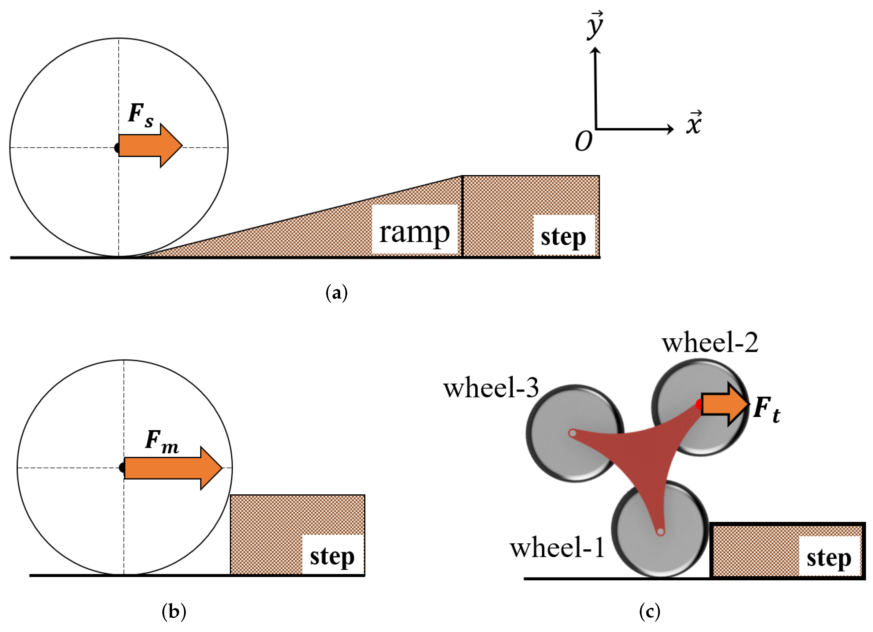
4. Gradient-Reduction Scheme

4.1. Step-Equivalent Gradient Model

As depicted in Figure 3a, the axle position is referred to as a point O, and the contact point between a wheel and a step is expressed as a point C. Next, the perpendicular of the line O C ¯ is regarded as a virtual slope, l m ; the gradient of l m is named a step-equivalent gradient. Similarly, the step-equivalent gradient configured when the wheel ascends the step is represented by θ m .
Figure 3b depicts another virtual slope, l d , and its perpendicular line, C S ¯ , when a gradient becomes smaller than θ m . Once l d can be adjusted to be gentler, another equivalent gradient is defined as θ d . If θ d is configured, an alternative O C ¯ around C is necessary. Therefore, a new rotational center point S is located on C S ¯ . Alternatively, to reduce θ d , S is assumed to exist on the C S ¯ obtained after rotating O C ¯ around C. In the following subsection, we describe the definition and derivation of S in detail.

4.2. Derivation of New Center of Rotation

Since θ d varies according to step heights, S is also linked to the height. In this subsection, an appropriate S to ascend a step is derived. As shown in Figure 4, the distance from S to C in the x direction is defined as l x d . Similarly, the distance from S to C in the y direction is expressed as l y d . The derived θ d is expressed:
θ d = sin 1 l x d S C ¯ .
From Equation (3), θ d depends on the relative lengths of l x d and l y d from C to S. As a computation method for generating S, where the distance between C and S varies, S is used for the new axle of rotation. From this, the length of the line O S ¯ is defined as a constant A, and an angle between O S ¯ and the ground parallel to x is defined as α . The trajectory of the points that can be taken up by S is a circle with a radius A. To minimize θ d , the slope of S C ¯ should be the steepest. Therefore, S C ¯ is a tangent to a circle passing through C. Therefore, taking the virtual center of the wheel to be the origin, the coordinates ( p , q ) of S are derived as follows.
Before the development of ( p , q ) , the radius of the wheel and the step height are defined as R and h, respectively. Because ( p , q ) is located on the circumference of radius A, the following equation can be established:
p 2 + q 2 = A 2 .
Moreover, since S C ¯ is a tangent to the circle passing through C ( = ( h ( 2 R h ) , R h ) ) , it can be replaced with:
p h ( 2 R h ) q ( R h ) = A 2 .
Moreover, because S C ¯ is a tangent to the circle passing through C ( = ( h ( 2 R h ) , R h ) ) , it can be replaced. From Equations (4) and (5), the coordinates ( p , q ) of S are given:
p = A 2 h ( 2 R h ) + A 4 h ( 2 R h ) R 2 [ A 2 { A 2 ( R h ) 2 } ] R 2 ,
q = A 2 ( R h ) + A 4 ( R h ) 2 R 2 [ A 2 { A 2 h ( 2 R h ) } ] R 2 .
From Equations (6) and (7), α can be calculated:
α = tan 1 q p = tan 1 A 2 ( R h ) + A 4 ( R h ) 2 R 2 [ A 2 { A 2 h ( 2 R h ) } ] A 2 h ( 2 R h ) + A 4 h ( 2 R h ) R 2 [ A 2 { A 2 ( R h ) 2 } ]
To help the understanding of our derivation, a wheel with an arbitrary S and α is depicted in Figure 5a. The distance from C to S in the x and y directions are l x d and l y d , respectively. Furthermore, F d from the balance of forces parallel to the virtual slope is derived:
F d = m g h ( 2 R h ) A cos α ( R h ) + A sin α .
when the position of S exists, as shown in Figure 5b, the U d of the axle is obtained:
U d = m g { h ( 2 R h ) A cos α } 2 + { ( R h ) + A sin α } 2 R + A .
when { h ( 2 R h ) A cos α } 2 + { ( R h ) + A sin α } 2 R + A is simply replaced with H h , Equation (6) is given:
U d = m g H h .
As shown in Figure 5b, H h denotes a reduced height.

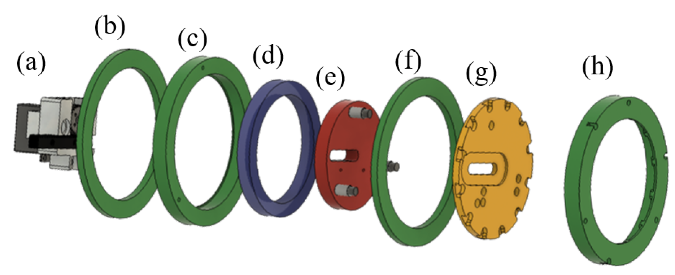
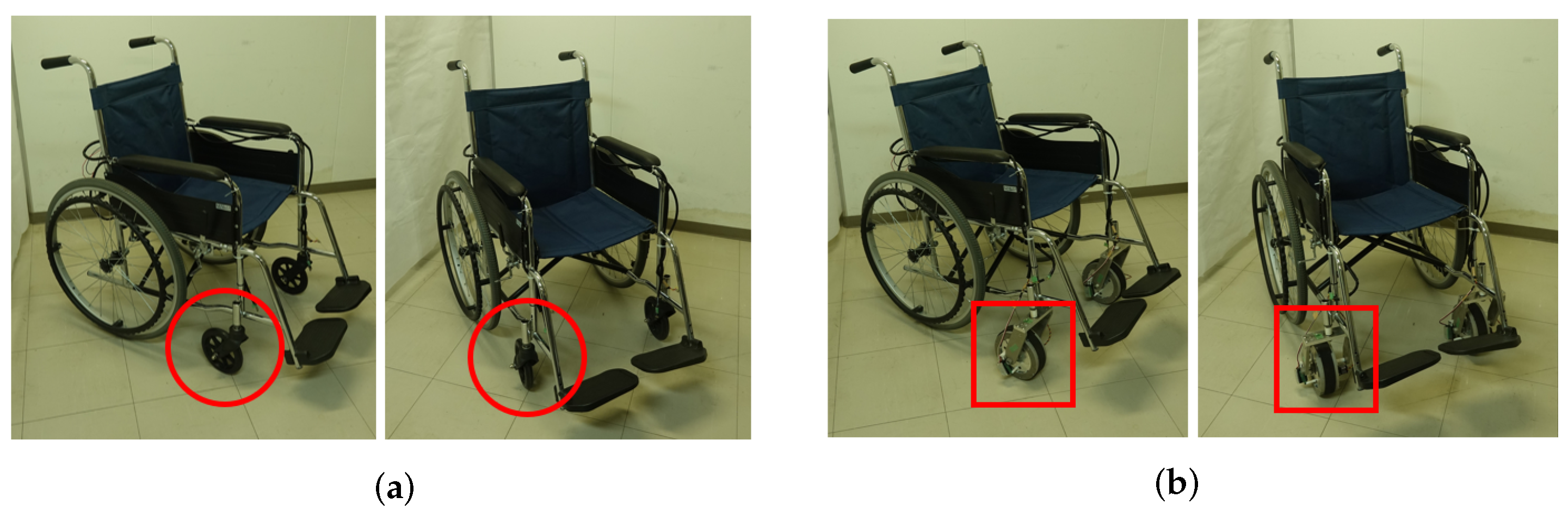
5. Implementation of Axel-Transitional Wheel Mechanism

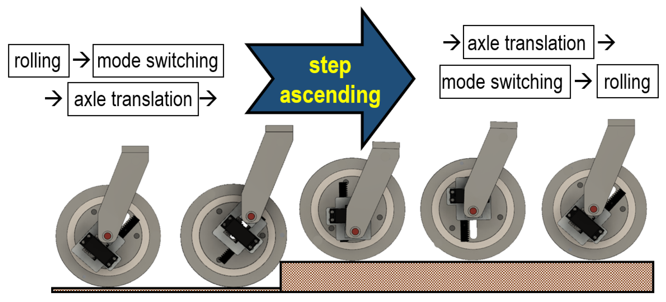
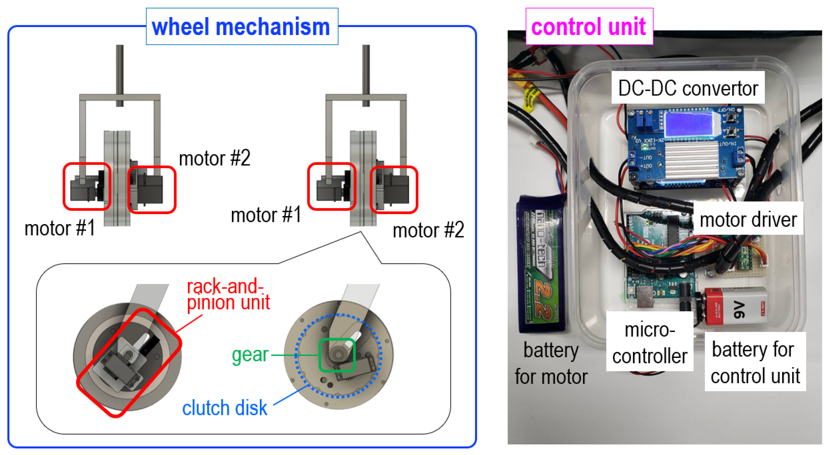
5.1. Details on Wheel Mechanism’s Configuration and Operation

Figure 6 depicts the implementation of an axle-translation operation. To generate the movement from O to S, an axle-translation wheel mechanism is established. The wheel mechanism consists of a wheel module and an axle-translation module attached to one side of the wheel. In this implementation, a rack-and-pinion unit in the axle-translation module is employed to translate the axle from O to S. In detail, this unit comprises a rack attached to the inner ring with screws and a pinion gear housed in a case, along with the axle.
Meanwhile, the wheel module is described. The parts in the wheel module are illustrated in Figure 7. This module is composed of an outer ring with the parts shown in Figure 7b,c,f,h: the inner ring, as shown in Figure 7e; the clutch disk, as shown in Figure 7g; and the bearing, as shown in Figure 7d. The stud bolts are used for the axles. Among these four parts comprising the outer ring, the outer ring in Figure 7h and the clutch disk in Figure 7g are designed to have multiple grooves on their edges.
Next, we explain the operation procedure for step ascending using the implemented wheel mechanism. Figure 8 depicts a schematic of the step-ascending process. This process can be divided into two modes: flat-surface traveling and step-ascending. Switching between these modes is realized by connecting and separating the inner and outer rings. In the flat-surface traveling mode, the inner and outer rings are separated, with only the outer ring rotating for movement. When the wheel comes into contact with a step, the inner and outer rings are joined, and the step-ascending mode is activated. After the mode is changed, the axle is translated, and the wheel ascends the step. Once the step-ascending motion is completed, the axle is translated again to return it to the center of the flat-surface traveling mode. Finally, the mode is switched back to the flat-surface traveling mode by separating the inner and outer rings, and flat-surface movement is resumed.
The two modes are switched using the clutch, as shown in Figure 9. The clutch is held together using the grooves in the outer ring (Figure 9 (h)) and the clutch disk (Figure 9 (g)). In the flat-surface traveling mode, the gear attached to the stud bolt pushes the clutch disk toward the direction for the spring to be compressed, which separates the clutch disk from the other ring. In the step-climbing mode, the clutch disk is pushed back and connected to the outer ring. The inner ring is in a free state when the clutch disk is separated; this allows the direction of the axle translation to be arbitrarily specified via the rotation of the clutch disk. Therefore, this enables the translation of the axle according to α derived from Equation (8).

5.2. Step-Ascending Prototype of Axle-Transitional Wheel Mechanism

In our developed wheel mechanism, the wheel diameter is set as 155 mm to maintain the diameter of a conventional wheel of wheelchairs (see Figure 10). The wheel width and weight are 55 mm and 1.7 kg, respectively, and aluminum is used as the wheel material. A pair of two motors is installed to power the clutch operation and the rack-and-pinion unit. Figure 11 shows the detailed motor installation and the electronic control unit for operating the wheel mechanism. The control unit is composed of the microcontroller, the motor driver, and power components, including batteries.
Next, a control schematic of the established wheel mechanism is depicted in Figure 12. First, servomotor-1, which powers the clutch, is driven through the motor driver using a microcontroller. Once the clutch is connected, servomotor-2, for the axle translation, is rotated. After the step-climbing motion is completed, servomotor-2 is used to return the axle to the center O. Thereafter, servomotor-1 is used to separate the clutch. Figure 13 shows the control flow based on the control schematic explained in Figure 12. As introduced in Figure 11, the control unit generates the operation commands and sends them to the wheel mechanism. According to the generated commands, the desired motor triggers its motions by pulse width modulation (PWM). The motor encoder offers closed-loop feedback signals by tracking the position of a motor’s shaft. Finally, the flat-surface movement is resumed. By repeating these processes, realizing different drives for the flat-surface movement and step ascending is possible through the control interfaces.

6. Evaluation Results and Discussion

6.1. Evaluation Directions and Experimental Settings

For comparative evaluations, two types of five cases related to wheel conditions were prepared. First, comparative simulations were performed to verify whether our gradient-reduction scheme reduces the horizontal force. The θ d of the wheel mounted is calculated using Equation (3). The horizontal force used for comparison is derived through Equation (9). For the comparison, examinations under four conditions were performed: a conventional wheel (case-1), a wheel with a vertically translated axle (case-2), a wheel with a horizontally translated axle (case-3), and our proposed wheel (case-4). Case-1 refers to a wheel with its axle located centrally. The conditions for case-1 can be derived by removing A cos α and A sin α from Equation (8). Case-2 is a wheel whose axle moves at α = 90 with respect to a step of any height. The conditions for case-2 can be derived by removing A cos α from Equation (8) and replacing A sin α with A. Case-3 is a wheel whose axle moves at α = 0 with respect to a step of any height. The conditions for case-3 can be derived by removing A sin α from Equation (8) and replacing A cos α with A.
Second, experiments employing four wheel prototypes were prepared to evaluate whether the gradient-reduction scheme and the axle-transitional wheel mechanism are effective for existing mobility aids. (To maintain the consistency of the evaluations and avoid confusion, the wheel numbers defined in the above simulation setting were used continually.) The following four types of wheels were used: a conventional wheel (case-1), a wheel with a vertically translated axle (case-2), our proposed wheel (case-4), and the three-wheel device (case-5). Specifically, as shown in Figure 14, our developed step-ascending prototype was mounted on a self-propelled wheelchair to conduct field experiments.

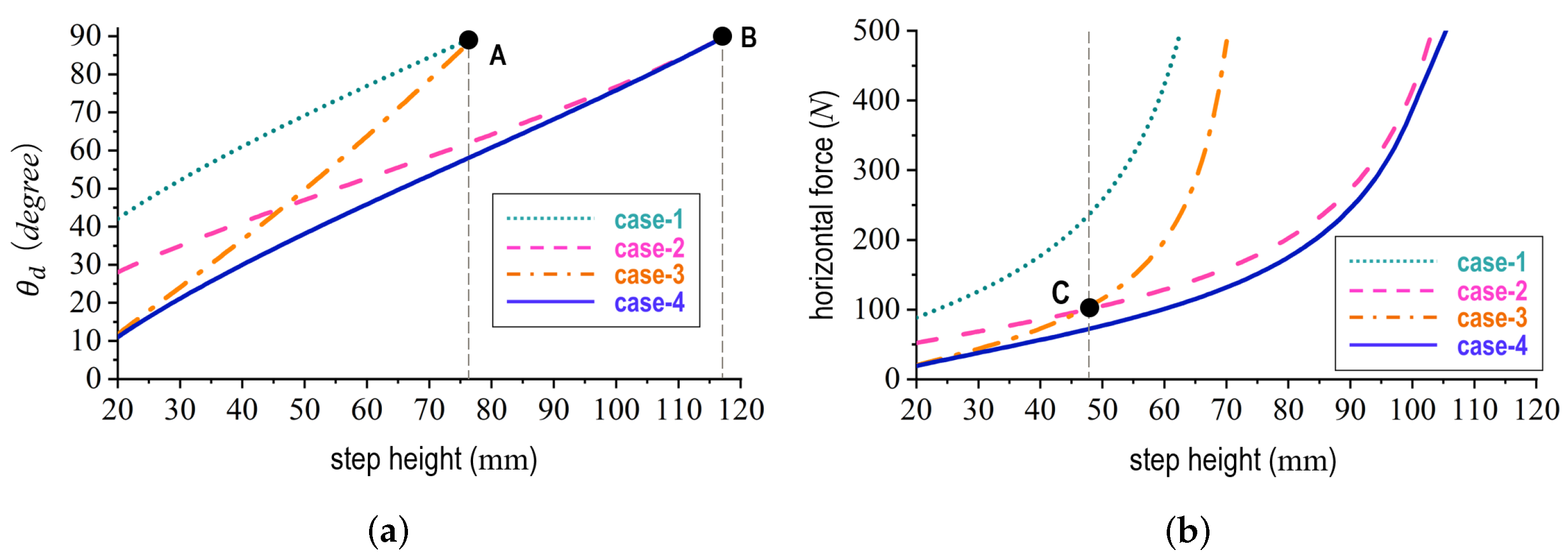
6.2. Simulation Results

Figure 15 plots the simulation results. The horizontal axis represents the step height h (mm), and the vertical axis represents θ d ( d e g ) in Figure 15a and the horizontal force (N) in Figure 15b, respectively. At line A in Figure 15a, case-1 and case-3 formed θ d of 90 at approximately 75 mm. That is, case-3 did not increase the range of the step heights capable of ascending. Moreover, from line B in Figure 15a, case-2 and case-4 formed θ d of 90 at approximately 120 mm. Therefore, case-2 and case-4 increased the range of the step heights capable of ascending.
Comparing case-2 and case-3 with line C in Figure 15b, for steps lower than 48 mm, case-3 achieved a greater reduction in force. However, for steps higher than 48 mm, case-2 achieved a greater reduction in force. Case-4 exhibited the smallest horizontal force compared to the other wheels for any step height. Based on the results, we confirmed that our proposed wheel reduces the horizontal force during step-ascending motion.

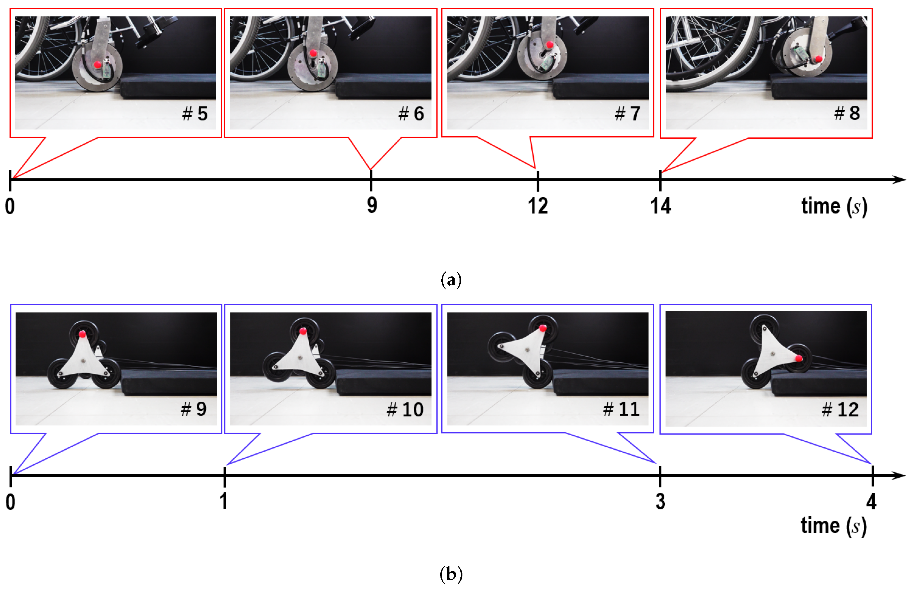
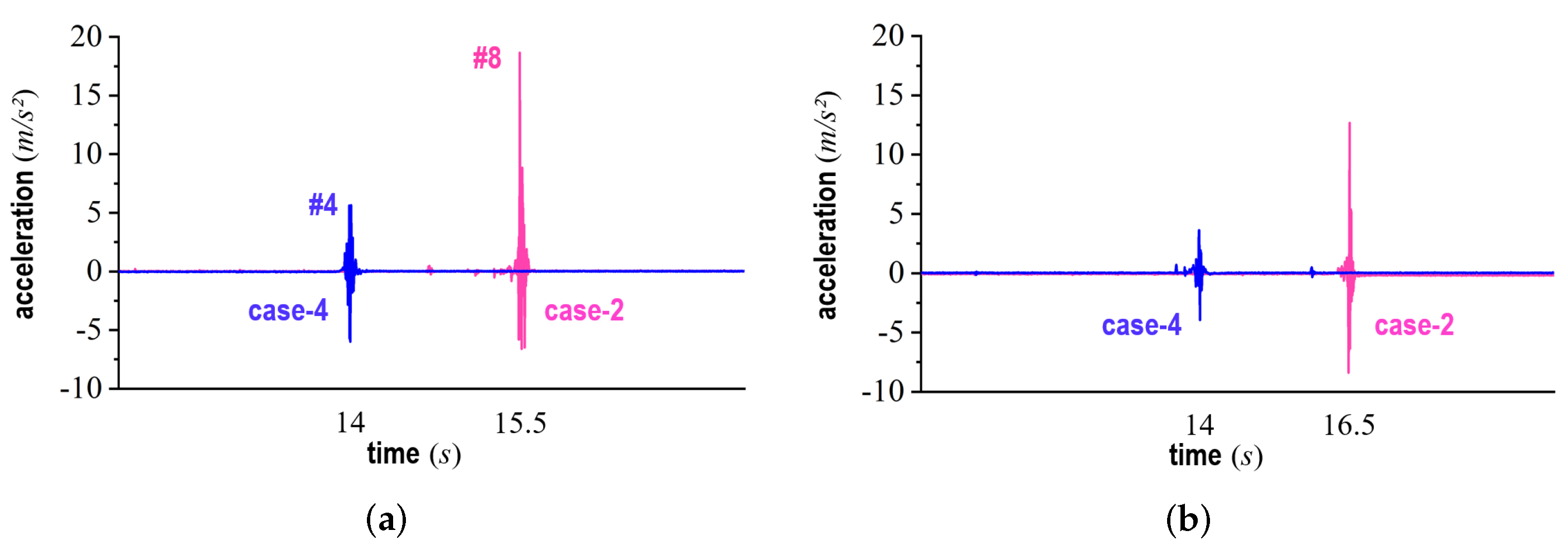
6.3. Experimental Results

Figure 16 and Figure 17 show continuous operation scenes for how individual wheels ascend a step of 20 mm in height where the horizontal direction indicates time over the step-ascending motion. In Figure 16, snapshots #1 through #4 present a series of step ascending by case-4. In Figure 17a, snapshots #5 through #8 show a series of step ascending by case-2. Moreover, in Figure 17b, snapshots #9 through #12 indicate a series of step ascending by case-5.
First, to evaluate whether our gradient-reduction scheme is effective for mobility-assisting systems, we measured the horizontal force. As shown in Figure 16 and Figure 17, the horizontal force was measured by pulling the wheels mounted on a self-propelled wheelchair at a constant speed in the x direction with respect to a flat surface. Three types of wheels were used in this measurement: case-1, case-2, and case-4. As conditions for the measurement experiments, we used four different step heights: 20, 30, 40, and 50 mm. Regarding the axle-translation angle for our proposed wheel, we set the angles of 11 , 21 , 30 , and 38 in accordance with Equation (8) and the height of each step.
The measurement results are presented in Figure 18. The frame numbers mean a specific motion scene in Figure 16 and Figure 17a. The vertical direction represents the horizontal force (N) required to ascend the step. From these results, no significant difference was observed in the required force for a step height of 10 mm. For all conditions of step heights, case-4 achieved a greater reduction in the horizontal force compared with the other wheels. On this basis, it can be argued that our gradient-reduction scheme is effective in reducing horizontal force. Furthermore, translating the axle according to the value of α obtained from Equation (8) is an important factor in the horizontal force reduction.
As mentioned in Section 2, we also evaluated whether vibration during step ascending was suppressed. To evaluate this, we represented the position of the axle during the step-ascending process as a trajectory. The confirmation of the trajectory was conducted for the three types of wheels: case-2, case-4, and case-5. To obtain the trajectories of individual axles, we traced the axles of case-2 and case-4, and the rotational axle of wheel-2 (as explained in Figure 3c) for case-5. In particular, for case-5, the distance from its central location to the axles of each wheel was set as equivalent to the radius of case-4. We obtained the trajectories of wheel-2 in case-5, which is the wheel climbing the step.
Figure 19 shows the axle trajectories during step ascending for the three types: case-4 in Figure 16, case-2 in Figure 17a by axle translation, and case-5 in Figure 17b. The horizontal and vertical axes represent the distance (mm) and height (mm), respectively. In Figure 19, we confirmed that case-2 was larger than case-4 given the distances from #2 and #6, after axle translation, to #4 and #8, the axle positions after ascending the step. The two types of axle-translation wheels (case-2 and case-4) had gentler slopes from #2 (or #6) to #4 (or #8) than the other wheel types. Therefore, case-4 could ascend the step while suppressing vibration. Next, comparing the trajectories from #7 to #8 and from #11 to #12, the height (from #3 to #4) was smaller for case-4 than for the other cases. Based on these analyses, it is verified that potential energy could be reduced for the step-ascending motion of case-4.
For case-2 and case-5, the axles fluctuate irregularly while ascending steps, generating potential energies. When the axle position reaches its lowest point during step ascending, this potential energy is converted into an impact against the entire wheel. To examine this impact, the loads applied to the step were measured. Regarding the height from the step surface to the axle position, the position of case-2 is higher than that of case-1. Therefore, it is expected that the difference in the impact is greater at lower step heights. For this reason, we conducted experiments at the step heights of 20 and 30 mm. The CLS-2KNB load-cell equipment (Tokyo Measuring Instruments Laboratory Co., Ltd., Tokyo, Japan) was used for the measurements. The average value was calculated from the load values of the load cells placed at the four corners of a step.
Figure 20 shows the load measurement results. In Figure 20a, the frame numbers mean a specific motion scene in Figure 16 and Figure 17a. The vertical direction represents the load (N) applied to the step. For case-2 and case-4, the maximum force was obtained for the moment the wheels contacted the surface of the step. At a step height of 20 mm, the load from case-2 was double the load from case-4. At a step height of 30 mm, the difference in force was reduced; however, case-4 had a smaller value. Based on this result, it was confirmed that step ascending with case-4 could be smoother and suppresses impacts.
Similar to the experiments shown in Figure 20, we measured the acceleration of the axle caused by the step-ascending motion. For these experiments, we used the same step heights as those in the load experiments. The TSND151 accelerometer (ATR-Promotions Inc., Kyoto, Japan) was used as the measurement device. The results from measuring the acceleration are shown in Figure 21. The frame numbers in Figure 21a mean a specific motion scene in Figure 16 and Figure 17a. The vertical direction represents acceleration (m/s 2 ) in the y axis. For a step height of 20 mm, case-4 exhibited an approximately 1 / 3 reduction in acceleration compared with case-2. For a step height of 30 mm, as expected, similar results were obtained, which were in line with the load measurement results. For the step ascending of case-4, even when using acceleration as an index, we verified that the impact during step ascending can be suppressed.
To investigate the inclination of the upper frame by axle translation and its control possibility based on electronic parts including sensors, the long bar on the step-ascending prototype shown in Figure 10 was installed as the support frame. Moreover, two proximity sensors were installed at both ends of the frame, as shown in Figure 22. These sensors measure distances to the ground. Considering the traveling direction of the prototype, the sensor of the front part and the sensor of the rear part are defined as sensor #1 and sensor #2, respectively. Here, d s 1 and d s 2 denote the distance measurements by each sensor. The distance between the axle and the ground is defined as d h . Next, four states are considered and defined. Firstly, state-1 indicates that the prototype is in contact with the step as depicted in Figure 22a. Secondly, a series of axle translation is defined as state-2 (see Figure 22b). Thirdly, the process during step ascending is expressed as state-3 (see Figure 22c). After the step-ascending motion, the axle is translated again to return it to the center of the flat-surface traveling mode. As presented in Figure 22d, state-4 means the preparation of the flat-surface traveling mode after returning to the original location of the axle.
Figure 23 shows the measurement results of d s 1 and d s 2 by sensor #1 and sensor #2, respectively. The blue bold dotted line and the red bold line indicate d s 1 and d s 2 , respectively. Moreover, the results of d s 2 d s 1 were plotted by using the black dashed line. According to the individual states, as explained in Figure 22, the measurement results are largely divided into four ranges. The four states in Figure 22 correspond to (1)-range, (2)-range, (3)-range, and (4)-range in Figure 23, respectively. Next, the step-ascending model is analyzed using the trends of d s 1 and d s 2 . Within (1)-range, the distance difference between d s 1 and d s 2 ( d s 2 d s 2 ), corresponding to the height of the step, occurred between sensor #1 and sensor #2. Next, d s 1 and d s 2 in (2)-range changed due to the axle translation, but the amount of the changes in d s 1 and d s 2 differed depending on the tilt of the support frame. Under (3)-range, d s 1 and d s 2 changed when the prototype ascended the step. Finally, due to the axle translating to return to the original position of the axle in (4)-range, d s 2 d s 2 occurred, and the frame tilted backward as the wheel ascended over the step, causing the distance difference. Consequently, the difference did not become 0 after step ascending. Based on this result, it was confirmed that the proposed mechanism allowed the prototype to maintain the inclination of the frame during step ascending. Moreover, it was demonstrated that the balanced inclinations by the electronic parts, including the sensors, could be controlled.
Figure 24 shows snapshots of experiments conducted under the environmental conditions of daily life after integrating the step-ascending wheel prototype into a self-propelled wheelchair. These experiments included straight-line and rotation motions around a corner in a hallway, rotational motions on a spot in an elevator, and step-ascending motions on a road, respectively. We observed that the self-propelled wheelchair with the proposed wheel could be controlled successfully in everyday environments. Specifically, Figure 24c shows the experimental scenes of rotation motions in an elevator. Our wheel mechanism features a simpler structure and more compact size and can fit easily into everyday environments.

6.4. Discussion

In this study, we proposed a gradient-reduction scheme for reducing horizontal force and vibration. Through the comparative experiments using wheel prototypes, we demonstrated the effectiveness of the proposed wheel mechanism. Although the wheel we used was a prototype, improvements are required for practical use. Specifically, a pair of two wheels that we developed for the experiments weighed approximately 3.4 kg; however, this is our first prototype, and we will consider using lighter materials for practical use in the future. Moreover, to move the clutch part and rack-and-pinion unit, two motors were used, respectively, but inventing ways to reduce the overall weight of the wheel is necessary.
During the experiments, we used a switch for our prototype to ensure the safety of users, which we believe can prevent falls. To improve the autonomy of step-ascending motions, we require advanced sensing technologies to detect step heights. Finally, the step-equivalent gradient can be autonomously generated according to step heights. These issues are being researched as part of our ongoing work.

7. Conclusions

The existing approaches for step ascending have problems, such as restrictions to locations where ascending is possible, bulky equipment size due to attachments such as actuators, and an increase in vibration levels. In this study, the effect on ascending steps using a virtual slope that results in laborsaving is introduced. Based on this concept, the step-equivalent gradient model that reduces the virtual gradient generated when ascending a step is proposed and established. Moreover, to evaluate the effectiveness of our proposed model, simulation tests in terms of the horizontal force and the gradient model were conducted. The simulation tests confirmed that the horizontal force could be reduced by generating another axle that is not the center point of the wheel. We also performed experimental evaluations and analyses using a wheel prototype. Our experiments demonstrated that a reduction in the horizontal force was possible even for steps of various heights. Moreover, the measurements of the axle trajectory, the load applied to the step, and the acceleration were conducted; these measurements confirmed that our proposed wheel mechanism can reduce vibrations compared to a wheel with the vertically translated axle and the three-wheel device. As a result, our gradient-reduction model can realize laborsaving and smooth-step ascending, which expands the activity range of users of mobility aids. Although our developed wheel was mounted on a wheelchair, its applications to other mobility aids can be also expected.

Author Contributions

Conceptualization, G.L.; methodology, G.L.; software, N.T. and Y.H.; validation, G.L., N.T. and Y.H.; formal analysis, G.L., N.T. and Y.H.; investigation, G.L. and N.T.; resources, G.L. and N.T.; data curation, G.L., N.T. and Y.H.; writing—original draft preparation, G.L.; writing—review and editing, G.L., N.T. and Y.H.; visualization, G.L., N.T. and Y.H.; supervision, G.L. and H.T.; project administration, G.L. and H.T. All authors have read and agreed to the published version of the manuscript.

Funding

This research received no external funding.

Institutional Review Board Statement

Not applicable.

Informed Consent Statement

Not applicable.

Data Availability Statement

Not applicable.

Acknowledgments

Not applicable.

Conflicts of Interest

The authors declare no conflict of interest.

References

  1. Zhang, X.; Mu, X.; Li, L.; Hamza, K.K. Research on steady characteristics of human-robot system for preventing elderly falls during walking. J. Mech. Sci. Technol. 2022, 36, 4775–4788. [Google Scholar] [CrossRef]
  2. Gonabadi, A.M.; Antonellis, P.; Malcolm, P. A system for simple robotic walking assistance with linear impulses at the center of mass. IEEE Trans. Neural Syst. Rehabil. Eng. 2020, 28, 1353–1362. [Google Scholar] [CrossRef] [PubMed]
  3. Matsumoto, N.; Togo, S.; Yokoi, H.; Jiang, Y. Motion Control of a Walking Support Robot Based on Gait Analysis. In Proceedings of the 2019 IEEE International Conference on Robotics and Biomimetics, Dali, China, 6–8 December 2019; pp. 1881–1885. [Google Scholar]
  4. Ohnuma, T.; Lee, G.; Chong, N.Y. Development of JARoW-II active robotic walker reflecting pelvic movements while walking. Intell. Serv. Robot. 2017, 10, 95–107. [Google Scholar] [CrossRef]
  5. Lee, G.; Ohnuma, T.; Chong, N.Y.; Lee, S.-G. Walking intent-based movement control for JAIST active robotic walker. IEEE Trans. Syst. Man, Cybern. Syst. 2014, 44, 665–672. [Google Scholar] [CrossRef]
  6. Phi, L.V.; Fujimoto, Y. A robotic cane for balance maintenance assistance. IEEE Trans. Ind. Inform. 2019, 15, 3998–4009. [Google Scholar] [CrossRef]
  7. Di, P.; Hasegawa, Y.; Nakagawa, S.; Sekiyama, K.; Fukuda, T.; Huang, J.; Huang, Q. Fall detection and prevention control using walking-aid cane robot. IEEE/ASME Trans. Mechatron. 2016, 21, 625–637. [Google Scholar] [CrossRef]
  8. Wu, X.; Ma, Y.; Yong, X.; Wang, C.; He, Y.; Li, N. Locomotion Mode Identification and Gait Phase Estimation for Exoskeletons During Continuous Multilocomotion Tasks. IEEE Trans. Cogn. Dev. Syst. 2021, 13, 45–56. [Google Scholar] [CrossRef]
  9. Wardana, A.A.; Takaki, T.; Jiang, M.; Ishii, I. Development of a single-wheeled inverted pendulum robot capable of climbing stairs. Adv. Robot. 2020, 34, 674–688. [Google Scholar] [CrossRef]
  10. Hassan, M.; Kadone, H.; Ueno, T.; Hada, Y.; Sankai, Y.; Suzuki, K. Feasibility of synergy-based exoskeleton robot control in hemiplegia. IEEE Trans. Neural Syst. Rehabil. Eng. 2018, 26, 1233–1242. [Google Scholar] [CrossRef]
  11. Choukou, M.A.; Best, K.L.; Potvin-Gilbert, M.; Routhier, F.; Lettre, J.; Gamache, S.; Borisoff, J.F.; Gagnon, D. Scoping review of propelling aids for manual wheelchairs. Assist. Technol. 2021, 33, 72–86. [Google Scholar] [CrossRef]
  12. Chocoteco, J.A.; Morales, R.; Feliu-Batlle, V. Enhancing the trajectory generation of a stair-climbing mobility system. Sensors 2017, 17, 2608. [Google Scholar] [CrossRef] [Green Version]
  13. Isaacson, M.; Barkay, D. Mobility scooters in urban environments: A research agenda. J. Transp. Health 2020, 18, 100917. [Google Scholar] [CrossRef] [PubMed]
  14. Akkaya, R.; Kazan, F.A. Design and implementation of a test setup for electric mobility scooter for the disabled. Meas. Control. 2019, 52, 1434–1444. [Google Scholar] [CrossRef]
  15. Sivakanthan, S.; Blaauw, E.; Greenhalgh, M.; Koontz, A.M.; Vegter, R.; Cooper, R.A. Person transfer assist systems: A literature review. Disabil. Rehabil. Assist. Technol. 2021, 16, 270–279. [Google Scholar] [CrossRef]
  16. Wu, J.; Shino, M. Hip lift transfer assistive system for reducing burden on caregiver’s waist. Sensors 2021, 21, 7548. [Google Scholar] [CrossRef] [PubMed]
  17. Blaauw, E.R.; Greenhalgh, M.; Vegter, R.; Bass, S.; Kulich, H.; Grindle, G.G.; Cooper, R.; Koontz, A.M.; Cooper, R.A. Assessment of muscle activation of caregivers performing dependent transfers with a novel robotic-assisted transfer device compared with the hoyer advance. Am. J. Phys. Med. Rehabil. 2021, 100, 885–894. [Google Scholar] [CrossRef]
  18. Ikeda, H.; Toyama, T.; Maki, D.; Sato, K.; Nakano, E. Cooperative step-climbing strategy using an autonomous wheelchair and a robot. Robot. Auton. Syst. 2021, 135, 103670. [Google Scholar] [CrossRef]
  19. Jiang, T.-C.; Yin, S.-H.; Tanaka, E. Wheelchair Able to Assist the Elderly to Move on Stairs and Stand Up. In Proceedings of the 2019 58th Annual Conference of the Society of Instrument and Control Engineers of Japan (SICE), Hiroshima, Japan, 10–13 September 2019; pp. 1168–1173. [Google Scholar] [CrossRef]
  20. Hong, J.; Park, G.; Lee, J.; Kim, J.; Kim, H.S.; Seo, T. Performance comparison of adaptive mechanisms of cleaning module to overcome step-shaped obstacles on facades. IEEE Access 2019, 7, 159879–159887. [Google Scholar] [CrossRef]
  21. Choi, J.-K.; Park, C.S.; Kitagawa, T.; Nakatani, K.; Sugii, H. Passive step-climbing mechanism for a mobility aid. Adv. Robot. 2009, 23, 45–64. [Google Scholar] [CrossRef]
  22. Nakajima, S. Stair-climbing gait for a four-wheeled vehicle. Robomech. J. 2020, 7, 20. [Google Scholar] [CrossRef] [Green Version]
  23. Kim, Y.; Lee, Y.; Lee, S.; Kim, J.; Kim, H.S.; Seo, T. STEP: A new mobile platform with 2-DOF transformable wheels for service robots. IEEE/ASME Trans. Mechatron. 2020, 25, 1859–1868. [Google Scholar] [CrossRef]
  24. Sasaki, K.; Suzuki, K. Active rotary-legs mechanism for stair-climbing mobility vehicle. IEEE Robot. Autom. Lett. 2018, 3, 2237–2244. [Google Scholar] [CrossRef]
  25. Munakata, Y.; Wada, M. A Novel Step Climbing Strategy for a Wheelchair with Active-Caster add-on Mechanism. In Proceedings of the 2015 IEEE/RSJ International Conference on Intelligent Robots and Systems, Hamburg, Germany, 28 September–2 October 2015; pp. 6324–6329. [Google Scholar] [CrossRef]
  26. Orita, Y.; Takaba, K.; Fukao, T. Human tracking of a crawler robot in climbing stairs. J. Robot. Mechatron. 2021, 33, 1338–1348. [Google Scholar] [CrossRef]
  27. Pan, L.-H.; Kuo, C.-N.; Huang, C.-Y.; Chou, J.J. The claw-wheel transformable hybrid robot with reliable stair climbing and high maneuverability. In Proceedings of the 2016 IEEE International Conference on Automation Science and Engineering, Fort Worth, TX, USA, 21–25 April 2016; pp. 233–238. [Google Scholar]
  28. Herbert, S.D.; Drenner, A.; Papanikolopoulos, N. Loper: A Quadruped-Hybrid Stair Climbing Robot. In Proceedings of the 2008 IEEE International Conference on Robotics and Automation, Pasadena, CA, USA, 19–23 May 2008; pp. 799–804. [Google Scholar]
  29. Yamauchi, B.M. PackBot: A versatile platform for military robotics. Proc. SPIE 2004, 5422, 228–237. [Google Scholar]
  30. Sasaki, K.; Eguchi, Y.; Suzuki, K. Stair-climbing wheelchair with lever propulsion control of rotary legs. Adv. Robot. 2020, 34, 802–813. [Google Scholar] [CrossRef]
Figure 1. Conceptual illustration of gradient minimization for mobility aids.
Electronics 12 01399 g001
Figure 2. Three cases to be employed during step ascending: (a) using ramp, (b) using actuators, (c) using three-wheel device.
Electronics 12 01399 g002
Figure 3. Illustration of step-equivalent gradient model. (a) Step-height-based equivalent gradient computation for existing wheels, (b) concept of slope minimization for step-height-based equivalent gradient model.
Electronics 12 01399 g003
Figure 4. Illustration of angle α derived from θ d to determine another axle.
Electronics 12 01399 g004
Figure 5. Illustration of axle translation based on α . (a) F d in Equation (9); (b) U d in Equation (10).
Electronics 12 01399 g005
Figure 6. Implementation concept of axel-transitional process using rack-and-pinion unit.
Electronics 12 01399 g006
Figure 7. Assembly details on wheel module ((a) rack-and-pinion unit, (b) outer ring (side of rack-and-pinion unit), (c) outer ring (around bearing), (d) bearing, (e) inner ring, (f) outer ring, (g) clutch disk, and (h) clutch).
Electronics 12 01399 g007
Figure 8. Step-ascending mode performed by wheel mechanism.
Electronics 12 01399 g008
Figure 9. Details on mode switching by using clutch unit where (g) and (h) indicate the clutch disk and the clutch, respectively.
Electronics 12 01399 g009
Figure 10. Step-ascending prototype and its specification.
Electronics 12 01399 g010
Figure 11. Details on the motor installation (left) of the wheel-mechanism prototype and the electronic components (right) of the control unit.
Electronics 12 01399 g011
Figure 12. Control schematic of step-ascending wheel prototype.
Electronics 12 01399 g012
Figure 13. Control flow according to operation commands based on the control unit assembled in Figure 11.
Electronics 12 01399 g013
Figure 14. Realization of self-propelled wheelchair using step-ascending prototype. (a) Conventional general wheel; (b) proposed step-ascending wheel.
Electronics 12 01399 g014
Figure 15. Analytic results for both required horizontal forces and step-height-based equivalent gradient when ascending a step (where case-1, case-2, case-3, and case-4 denote a conventional wheel, a wheel with vertically translated axle, a wheel with horizontally translated axle, and the proposed wheel, respectively.) (a) Required horizontal forces; (b) step-height-based equivalent gradient.
Electronics 12 01399 g015
Figure 16. Experimental scene for step-ascending mode using the proposed wheel prototype (case-4) where the horizontal direction indicates time over the step-ascending motion.
Electronics 12 01399 g016
Figure 17. Experimental scenes for comparison analyses where the horizontal direction indicates time over the step-ascending motion according to different wheel types. (a) Case-2: wheel with vertically translated axle; (b) case-5: three-wheel device.
Electronics 12 01399 g017
Figure 18. Comparison results for required horizontal forces during step ascending where case-1, case-2, and case-4 denote a conventional wheel, a wheel with vertically translated axle, and the proposed wheel, respectively. Moreover, the frame numbers under the case of 20 mm mean a specific motion scene in Figure 16 and Figure 17a, respectively. (a) Step height of 20 mm; (b) step height of 30 mm; (c) step height of 40 mm; (d) step height of 50 mm.
Electronics 12 01399 g018
Figure 19. Comparison results for trajectories of axle and wheel’s center location when climbing a step where case-2, case-4, and case-5 denote the wheel with vertically translated axle, the proposed wheel, and the three-wheel device, respectively.
Electronics 12 01399 g019
Figure 20. Comparison results for impact forces generated when climbing steps where case-2 and case-4 denote the wheel with a vertically translated axle and the proposed wheel, respectively. Moreover, the frame numbers under the case of 20 mm mean a specific motion scene in Figure 16 and Figure 17a, respectively. (a) Step height of 20 mm, (b) step height of 30 mm.
Electronics 12 01399 g020
Figure 21. Comparison results for accelerations triggered when climbing steps where case-2 and case-4 denote the wheel with a vertically translated axle and the proposed wheel, respectively. Moreover, the frame numbers under the case of 20 mm mean a specific motion scene in Figure 16 and Figure 17a, respectively. (a) Step height of 20 mm, (b) step height of 30 mm.
Electronics 12 01399 g021
Figure 22. Illustration of experiments to investigate the inclination of the support frame by axle translation and its control possibility by electronic parts. (a) State-1: contact with the step, (b) state-2: axle translation, (c) state-3: step ascending, (d) state-4: returning to original axle location.
Electronics 12 01399 g022
Figure 23. Measurement results of d s 1 and d s 2 by sensor #1 and sensor #2.
Electronics 12 01399 g023
Figure 24. Experimental scenes for a self-propelled wheelchair with the proposed wheel under the environmental conditions of daily lives. (a) Straight-line motions; (b) rotation motions in a hallway with a corner; (c) rotation motions in an elevator; (d) step-ascending motion.
Electronics 12 01399 g024aElectronics 12 01399 g024b
Disclaimer/Publisher’s Note: The statements, opinions and data contained in all publications are solely those of the individual author(s) and contributor(s) and not of MDPI and/or the editor(s). MDPI and/or the editor(s) disclaim responsibility for any injury to people or property resulting from any ideas, methods, instructions or products referred to in the content.

