Article

Dynamic Target Tracking of Small UAVs in Unstructured Environment

1
School of Automation, Northwestern Polytechnical University, Xi’an 710072, China
2
Xi’an Modern Control Technology Research Institute, Xi’an 710065, China
*
Author to whom correspondence should be addressed.
Electronics 2023, 12(5), 1078; https://doi.org/10.3390/electronics12051078
Submission received: 11 January 2023 / Revised: 7 February 2023 / Accepted: 16 February 2023 / Published: 21 February 2023
(This article belongs to the Special Issue Robotics Vision in Challenging Environment and Applications)

Abstract

:
In this paper, an adaptive multi-rotor UAV system of dynamic target tracking and path planning is proposed for the problems of occlusion, lighting change, and similar target interference in an unstructured environment. A DTE-tracker module is designed, consisting of a detector, tracker, and examiner, and proposes a dynamic target capture mechanism to improve the robustness and continuity of target tracking in complex environments. A DWA local path planning algorithm based on a dynamic target tracking task is proposed to control the yaw of the UAV to accurately locate specific targets in the center of the image, and finally achieve the purpose of stable tracking. A UAV platform was built equipped with an onboard computer, laser sensor, and visual sensor, and a series of target tracking and path planning experiments were carried out to verify the effectiveness of the method and test the performance of the algorithm in a complex jungle environment.

1. Introduction

With the development of artificial intelligence and computer vision technology, unmanned aerial vehicle (UAV) visual target tracking technology has become the current research focus [1]. Small UAVs with low cost and flexible flight have been widely used in outdoor monitoring [2], power detection [3], agricultural production [4], and tracking tasks [5]. For these complex scenarios, long-term, stable target tracking and smooth, reasonable path planning are essential. However, when a non-cooperative dynamic target enters an unstructured outdoor environment, there are problems of target loss and inaccurate positioning due to obstacle occlusion and similar target interference. In addition, the computing resources and capabilities of small UAV platforms are very limited. Therefore, it is challenging to develop real-time, efficient, and robust tracking and path-planning schemes.
In [5], a quadrotor UAV based on vision was designed, and a high-precision flight test was conducted in an unknown indoor scene. Liu et al. [6] used lasers and cameras to estimate the distance and KCF algorithm to track the target. Zhao et al. [7] develop a framework for moving vehicle detecting, tracking, and geolocating based on a monocular camera, a GPS receiver, and inertial measurement units (IMUs) sensors. However, the GPS signal is usually unavailable in the loaded jungle environment. In [8], a UAV equipped with a camera completed the task of tracking a ground non-cooperative mobile vehicle, which was running on a structured road and was not obstructed by trees. This work greatly reduced the difficulty of tracking and path planning. However, the GPS signal is usually unavailable in the loaded jungle environment. In [9], a new method for tracking moving targets in the unknown unstructured outdoor scenes was proposed, but the method could not cope with the change of target scale and did not solve the problem of stable tracking of dynamic random targets. Giusti et al. [10] studied the autonomous work of quadrotors in forest scenes or mountain paths, and proposed a different approach based on a deep neural network used as a supervised image classifier. Because the selected forest scene path is wide enough for UAVs to navigate, it did not study the function of autonomous obstacle avoidance except tracking in [10]. In addition, most of the above work uses traditional tracking methods, which cannot perform apparent modeling of moving objects in complex environments. The method in [11] is to use a convolutional neural network to model the appearance of the target and track it by means of re-detection, but it is difficult to ensure the real-time performance of this method on the UAV onboard computer.
In order to solve the problems of large changes in the apparent model of target tracking in complex environments, occlusion of targets, and path planning in unstructured environments, this paper proposes a new framework for dynamic target tracking and path planning in forest environments using small UAVs. The main contributions are as follows:
(a) A DTE-tracker framework consisting of a detector, tracker, and examiner is proposed. The tracking result examination and target capture mechanism are established. The detection and examination windows are adjusted adaptively to solve the problems of target occlusion, similar target interference, and target re-initialization in a complex jungle environment.
(b) A DWA local path planning algorithm based on a dynamic target tracking task is proposed, which can adaptively adjust the yaw angle of the UAV to make the tracking target located in the center of the camera image, so as to achieve accurate tracking and path planning.
(c) A multi-rotor UAV experimental platform is designed to verify the stability of the tracking algorithm in the unstructured jungle environment with target occlusion and interference, and the robustness of the UAV real-time obstacle avoidance and path planning algorithm when the target passes through the jungle.
The rest of this paper is organized as follows: Section 2 introduces the DTE-tracker system framework and shows the methods of dynamic tracking result examination and target re-capture, as well as the positioning method based on an RGB-D camera. Section 3 proposes an improved DWA local path planning algorithm based on the target-following tasks. The experiment and results are shown in Section 4. Finally, a brief summary and future work are presented in Section 5.

2. System Framework and Research on Tracking Method

This paper mainly studies how UAVs track a moving target in a complex unstructured jungle environment and plan a reliable path at the same time. Figure 1 shows the system structure framework, which is mainly composed of five modules: DTE-tracker, localizer, pose solver, path planner, and controller. The DTE-tracker captures the image information of a specific target and selects its frame to send to the localizer. The pose solver inherits the odometer module, which can obtain the real-time position information of the UAV. The localizer combines the pose information with the two-dimensional data of the target in the image to further obtain the three-dimensional coordinates of the target. The path planner uses the DWA algorithm based on dynamic target tracking tasks to plan the reasonable track points and yaw angles of the UAV. In the controller, according to the data obtained from the previous module, the UAV is given the underlying control logic to obtain a high-value path to track the target and avoid obstacles robustly.

2.1. DTE-Tracker Design

The DTE-tracker framework proposed in this paper consists of a detector, examiner, and tracker, as shown in Figure 2. After the UAV captures the global image through the camera sensor, it sends it to the YOLOv5 [12] detector to obtain the target classification information. Because the image information of the middle target in the complex environment may have been interfered with or the detector may have false detection, the detection results need to be sent to SiameseNet [13] for inspection to find the correct target. Finally, the specific two-dimensional target in the image is sent to SiamRPN [14] as the initialization of the tracker. The tracker performs the task of target tracking in subsequent frames and monitors the tracking results in real-time. When the tracking results are normal, it directly inputs them to the localizer to obtain the target position. Otherwise, the tracking results will be checked by the examiner, and only those passing the examiner can be sent to the localizer. Otherwise, the detector is re-called to search for the correct target and follow the template of the new trace.
Detector and initialization. The detector in this paper uses the YOLOv5 algorithm to narrow the detection range when starting to search for the target and reuses the detection to initialize the target after the target is lost. Compared with the classic YOLOv3 [15] and YOLOv4 [16], YOLOv5 has been optimized in data set enhancement, adaptive anchor frame calculation, adaptive image scaling, feature extraction, and fusion, and is greatly improved in detection speed and accuracy. In addition, the depth of the YOLOv5 network and the size of the model can be adjusted according to the needs of the task. Considering the limited computing resources of UAVs, this paper selects the YOLOv5-s model, which gives consideration to both speed and accuracy. The YOLOv5 detector can regress the position of the target in the image only by processing the input image once.
In Figure 3a, the output of YOLOv5 is a bounding box, which shows the class, confidence, location, and scale of the detection target. In the jungle environment, due to light changes, motion blur, target scale changes, and interference from similar targets, objects with characteristics similar to specific targets may exist. YOLOv5 detects all potential targets in the search frame, but cannot distinguish targets belonging to the same category. Therefore, one needs to use the examiner to select specific targets from the test results. Once the position and size of a specific target in the image are found, they will be sent to the tracker for initialization. Otherwise, the search will continue until the target is found. If the target is lost during tracking, the same search process is applied.
Examiner and result monitoring. In the process of tracking, when there is occlusion or interference from pedestrians, tree trunks, and other objects with similar characteristic scales, it is easy to lose the tracking or even follow the wrong target, so this paper sets up an examiner to monitor the tracking results. In order to extract the characteristics of the target and compare the similarity between the tracked target and the specific target, we use the SiameseNet as the examiner. This paper uses the ShuffleNetV2 [17] lightweight network as the backbone feature extraction network of SiameseNet. ShuffleNetV2 uses channel split operation and point-wise group cone and bottle-like structures to enhance the interactivity of information, realize the reuse of features, achieve high accuracy, and greatly improve the efficiency of target feature extraction. For the examiner, when inputting the image of the target to be tracked and the real target, the output σ is the similarity score within the range of [0, 1]. The closer the score is to 1, the higher the similarity between the two inputs.
Tracker and target tracking. The tracker adopts the SiamRPN tracking algorithm, which is an end-to-end offline training network and is composed of a siamese subnetwork and a region proposal subnetwork. The siamese network uses a lightweight AlextNet [18] as the backbone network for feature extraction, which can run on the UAV in real-time. RPN omits multi-scale testing and online fine-tuning strategy, which improves the speed of model reasoning. The SiamRPN overall framework consists of two input branches, one is the target template, and the other is the search area, where the target template is initialized in the first frame. In the tracking phase, SiamRPN regards tracking as a one-shot detection task, that is, it regards the target in the first frame as a template for detection, and detects similar targets in subsequent frames. As shown in Figure 3b, SiamRPN output is a bounding box and confidence level α . The bounding box represents the position and scale of the target in the image. The range of the confidence α is [0, 1], indicating that the target is an overview of the foreground and background. It is worth noting that SiamRPN does not need to distinguish between target categories.

2.2. Dynamic Result Monitor and Target Recapture

In Section 2.1, setting detector and examiner is to optimize the target tracking results and makes up for the shortcomings of the tracker. In order to save computing resources of airborne computers, this paper proposes a strategy of result checking and target re-acquisition, which can be called when necessary.
Dynamic tracking result monitoring. When the human target moves in the jungle environment, the tracking results will drift to the wrong target due to the interference of tree trunks, shrubs, and similar targets, requiring the results to be checked. As can be seen from Section 2.1, the confidence α is the key to tracking the target correctly. Therefore, monitoring the change of the α curve can judge the tracking state effectively. Figure 4 shows the three states of the tracking results: normal, short-term interference, and long-term occlusion. The horizontal coordinate is the frame number of the video, and the vertical coordinate is the response score α . When the target is tracked normally, such as α as shown in Figure 4a, the value is close to 1.0. In Figure 4b α value fluctuates greatly from 1.0 to 0 and then to 1. At this time, the tracking result drifts, and the tracking box may track the wrong target. One needs to start the examiner to check whether the target is correct. When target tracking is lost, α has no change after dropping from 1 to 0.
This article uses the sliding window method to check and monitor the response of the α curve in Figure 4b. As shown in Figure 5, the sliding window only slides in one dimension. Set the width of the sliding window to w. The corresponding frame number at the beginning of the sliding window is f 0 , and the response score is α f 0 . The corresponding frame at the end is f w , and the score is α f w . The monitoring mechanism can be expressed by Formula (1):
μ = α f 0 α f m i n α f w α f m i n
α f m i n = min α f i | i = 0 , 1 , 2 , , w
where α f m i n is the minimum value of the response score and i is the i-th frame in the sliding window. The range of μ value is [0, 1]. When μ exceeds threshold μ t , i.e., short-time occlusion, as shown in Figure 4b, the time to start the examiner is μ > μ t .
Target recapture mechanism. There are three situations where the detector needs to be recalled for global target search. First, when the target encounters long-term occlusion, the tracking bounding box will stop or drift. When the target reappears in the field of view, the tracker cannot recapture the target due to its own candidate box selection mechanism. Similar to the previous article, we still use the sliding window method to judge the state of target tracking. Figure 4c shows the confidence α of the bounding box will drop to zero and remain for a long time when the tracking fails. Set α f m a x is the maximum confidence value in the sliding window frame.
α f m a x = max α f i | i = 0 , 1 , 2 , , w
If α f m a x < α t , target tracking will be considered as failed, where α t is a threshold value, and the detector will be started for a global search. Second, when the tracking result fails to pass the examiner, that is, the tracking target is wrong, the detector will be started. Third, due to the relative motion between the UAV and the target, when the distance between the target and the UAV is too large, the target scale will change, resulting in lower tracking accuracy and a worse effect. In this paper, ϕ is used to describe a relative average distance in a sliding window, as shown in the following formula:
ϕ = i = 1 w d i n i t d i w
where d i n i t is the distance between the target and the UAV when the tracker is initialized, d i is the distance between the target and the UAV in the current frame, and w is the frame number of the sliding window. Considering the above three situations, we use γ as the discriminant of the calling detector:
γ = max α f m a x α t , σ f i σ t , ϕ t ϕ
where σ f is the output of the examiner in Section 2.1, α t , σ t , and ϕ t is the corresponding threshold, respectively. When γ < 0 means that at least one condition reaches the threshold, the detector will be started calling to recapture the target.

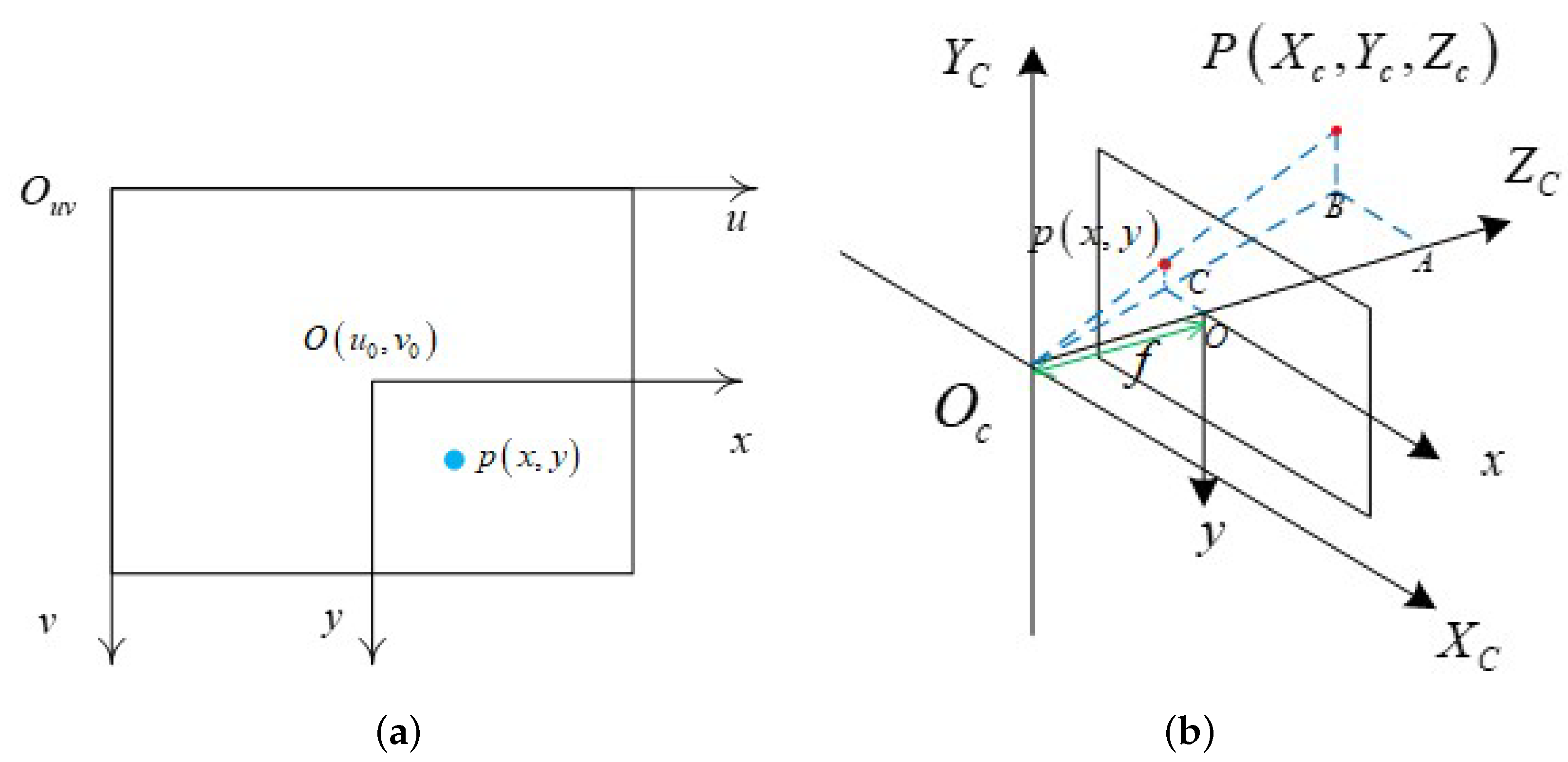
2.3. Target Location Based on RGB-D Camera

This section describes the functions of the localizer in the UAV dynamic target tracking system. The target in the image can be tracked using the DTE-tracker module, and then the target’s coordinates will be converted into the coordinates in the world coordinate system using the image information and the sensor depth information. As shown in Figure 6a, the pixel coordinate system is a two-dimensional coordinate system, taking the vertex at the top left corner of the camera field of view image as the origin, and the coordinate axes u and v point to the right and down respectively. As shown in Figure 6b, the origin of the camera coordinate system is the optical center of the camera, and z c direction points in front of the camera, x c direction is the right side of the camera image, and y c direction points below the camera image. In addition, the coordinates under the camera coordinate system can be converted to the world coordinate system through rigid body transformation, including rotation transformation and translation transformation. Assume that the coordinates of the measured target center in the image coordinate system are ( u o , v o ) and ( x c , y c , z c ) are the coordinates in the camera coordinate system.
Figure 7 shows the coordinate transformation diagram. The origin of the world coordinate system is the initial takeoff position of the UAV. Where d is the distance from the target to the optical center of the camera. According to the camera aperture imaging principle, d can be calculated with d = H f / h . And the value of d is equal to the depth of the depth camera Z c . Where h is the height of the target, H is the height of the tracking boundary box of the target in the image, and f is the focal length of the camera. ( X b , Y b , Z b ) is the UAV body coordinate system, which is obtained by rotating the camera coordinate system.
z c u v 1 = 1 d x 0 u o 0 1 d y v o 0 0 1 f 0 0 0 0 f 0 0 0 0 0 1 r 00 r 01 r 02 T X r 10 r 11 r 12 T Y r 20 r 21 r 22 T Z 0 0 0 1 x w y w z w 1
Formula (6) gives the formula for image coordinates to world coordinates, where ( x w , y w , z w ) represents the coordinates of the target in the world coordinate system, ( r 00 , r 01 , , r 22 ) represents the rotation transformation matrix, ( T X , T Y , T Z ) represents the translation transformation vector, f represents the focal length of the camera, and d x , d y are the actual physical size of the pixel on the light-sensitive chip. In particular, the rotation matrix and translation vector can be obtained from the position and attitude information of the UAV’s visual odometer.

3. DWA Path Planning Based on Dynamic Target Tracking

This paper proposes a DWA [19] path planning algorithm based on a dynamic target tracking task, which adds a new constraint to the angular velocity of the UAV. The UAV can always face the human body when planning the path locally, ensuring that the human target is in the center of the camera, so as to achieve stable tracking. Its core idea is to sample multiple groups of velocities ( v 1 , ω 1 ) , ( v 2 , ω 2 ) , , ( v m , ω m ) , and simulate the movement track of the UAV in the next period of time according to these speeds. Then an evaluation function is designed to score the trajectory, and the best-predicted trajectory is selected as the current motion path of the UAV. The algorithm process is as follows:
At time t 0 , the position of the UAV is ( x t 0 , y t 0 , θ t 0 ) , the speed is ( v x , v y , ω t 0 ) , and the control cycle is Δ t . Since the UAV has omnidirectional motion, the kinematics equation in the two-dimensional Cartesian coordinate system Oxy is:
x ( t n ) = x ( t 0 ) + v x Δ t cos θ v y Δ t sin θ y ( t n ) = y ( t 0 ) + v x Δ t sin θ + v y Δ t cos θ θ ( t n ) = θ ( t 0 ) + ω Δ t
where, position ( x t 0 , y t 0 ) is the coordinate of UAV in the world coordinate system and θ t 0 is the yaw angle of the UAV. Velocity coordinate ( v x , v y ) is in the UAV body coordinate system.
In the DWA algorithm, the dynamic window is based on UAV’s linear velocity ( v x + 1 , v y + 1 ) and angular velocity ω t + 1 within the control cycle, which the achievable range boundary is taken as the velocity space. Set the maximum linear acceleration ( a x m a x , a y m a x ) and angular acceleration β m a x , the range of UAV linear velocity and angular velocity in the control cycle is:
v x v x a x m a x Δ t , v x + a x m a x Δ t v y v y a y m a x Δ t , v y + a y m a x Δ t ω ω β m a x Δ t , ω a + β m a x Δ t
Formula (8) is the UAV linear velocity ( v x + 1 , v y + 1 and angular velocity ω t + 1 can be selected in Δ t time. After considering the limit of UAV acceleration, it is also necessary to consider the limit of v m a x and ω m a x , where v m a x and ω m a x are the maximum values of UAV linear velocity and angular velocity, respectively. At this time, the speed range of the UAV is:
v x 2 + v y 2 v m a x 2 ω t ω 1 , ω 2 ω 1 = max { ω m a x , ω t 0 β m a x Δ t } ω 2 = min { ω m a x , ω t 0 + β m a x Δ t }
According to the characteristics of the dynamic target tracking task and inspired by the article [20], the UAV needs to face the target human body to ensure that the human body is in the center of the camera’s field of view during the tracking process. New constraints on the diagonal speed need to be added to the local path planning.
As shown in Figure 8, θ refers to the angle between the positive direction of the camera and the line connection between the UAV and the target. In the process of the UAV following the target, it is necessary to calculate the relative positions of the human body and the machine in real-time to prevent the camera from failing to capture the target due to the movement of the target, which leads to the failure of the tracking task. Therefore, in the DWA speed sampling step, we calculate the appropriate angular velocity ω according to the included angle θ . The angular velocity ω can vary with θ to make the UAV quickly adjust the yaw angle and ensure that the target does not exceed the camera’s viewing angle.
As shown in Figure 9, the angular velocity is calculated using a piecewise curve model. θ m a x and ω m a x represent, respectively, the limit of the maximum angle of view and angular velocity of the camera. θ m a x is determined by different camera field angles. What is different from the article [20] is that the segmented curve model in this paper is smooth, and its curve slope will not change suddenly, that is to say, the change of angular velocity of an unmanned aerial vehicle will be more stable, and there will be no sudden jitter of the head. The angular velocity formula of the segmented curve is given by Formula (10):
ω = ω m a x 1 + e c x + b , 0 < θ < θ m a x ω m a x 1 + e c x + b , θ m a x < θ < 0 0 , θ = 0
where c and b are the parameter set by θ m a x , which can be set to π / 30 and 5 respectively.
After the constraint conditions of velocity and angular velocity are obtained, discrete sampling is carried out for and to obtain many velocity values ( v x 1 , v y 1 , ω 1 ) , ( v x 2 , v y 2 , ω 2 ) , , ( v x m , v y m , ω m ) . Then track simulation is carried out according to the speed value. The speed is unchanged during the simulation, and the simulation duration is D T . The kinematics model used is Formula (7). As shown in Figure 10, according to speed sampling, the red curve is the predicted track curve of each group of speed in D T time. The blue curve is the actual movement route of the target or the expected UAV’s route.
Finally, the evaluation function G ( v x , v y , ω ) is used to evaluate the track quality. The evaluation function comprehensively considers the position relationship between UAV and the target point, obstacle information, UAV speed information, etc. Finally, the speed value corresponding to the track with the highest score is sent to the UAV the next time. According to the requirements of the dynamic target-following task, the evaluation function adopted in the paper is calculated as follows:
G ( v x , v y , ω ) = σ τ 1 · a n g l ( v x , v y , ω ) + τ 2 · o b s ( v x , v y , ω ) + τ 1 · v e l ( v x , v y , ω )
Among them, τ 1 , τ 2 , τ 3 are the weight of the three scoring items, σ ( · ) is used to normalize the scores of each track. The criterion of normalization is to divide each item by the sum of each item. Taking the heading score item as an example, its normalization calculation formula is as follows:
σ τ 1 · a n g l i ( v x , v y , ω ) = γ 1 · a n g l i ( v x , v y , ω ) i = 1 n a n g l i ( v x , v y , ω )
where, a n g l i ( v x , v y , ω ) represents the i-th track to be evaluated, and n is the sampling number of all predicted tracks. The specific meanings of the three scoring functions are as follows:
(1) a n g l ( v x , v y , ω ) is a scoring item of the UAV heading, which aims to measure the deviation degree between the UAV terminal speed of the predicted trajectory and the dynamic target. We hope that the heading angle of the UAV ensures that the tracking target is in the center of the camera’s field of view. Set the heading angle as θ h e a d , the scoring function is:
a n g l ( v x , v y , ω ) = 180 θ h e a d θ m a x · θ h e a d
(2) o b s ( v x , v y , ω ) is an obstacle evaluation function, which is used to measure the distance score between the UAV flight path and the obstacle to ensure UAV flight safety. This function usually takes the distance between the flight path and the nearest obstacle. When the airborne radar cannot detect obstacles, the function is set as a constant; when the obstacle detection distance is less than the safe flight distance of the UAV, the simulation track is discarded. The specific obstacle evaluation function is:
o b s ( v x , v y , ω ) = d c o n t , d > d s e a r c h min { d i s t i ( v x , v y , ω ) | i = 1 , 2 , , n } , d t h d < d < d s e a r c h 0 , d < d t h d
where, d c o n t is a constant, d s e a r c h is the UAV radar detection range, d t h d is the safe flight distance of UAV and d i s t i is the distance between the UAV and the i t h obstacle around the track.
(3) v e l ( v x , v y , ω ) is used to evaluate the score of the track with fast flight speed in the safe track. The value is the modulus of the resultant velocity.
Based on the above evaluation functions and speed constraints, the UAV can safely and stably fly and avoid obstacles, maintain the direction of the UAV, and can be controlled to complete the task of dynamic target tracking.

4. Stable Tracking Experiment of Target in Jungle Environment

In this section, data sets were collected to train the detector and examiner. Then the DTE-tracker module was deployed on the airborne computer to test the real-time performance and compare the accuracy of the algorithm. Finally, we built a new type of small quadrotor platform and carried out tracking and path planning experiments on dynamic human targets in outdoor small forest environments.

4.1. Hardware Platform

The test site was an unstructured forest environment, in which GPS location information was denied. Therefore, a small quadrotor platform that did not rely on GPS and was equipped with various sensors was designed to be able to sense the environment independently. As shown in Figure 11, it was mainly composed of five parts, namely, a depth camera (Realsense d435i), VIO camera (Realsense T265), fixed altitude laser radar (HOKUTO UTM-30), 2-D laser radar, and airborne computer (Xavier NX). The image and depth information of dynamic targets were obtained from D435i. T265 was used to locate the UAV itself. UTM-30 could accurately measure the height of the UAV. 2-D laser radar was used to detect obstacles. Xavier NX was used as the airborne computing center, realizing the whole process of tracking and positioning. The communication between each module was completed by the ROS system.

4.2. DTE-Tracker Experiment

In order to track specific dynamic human targets in the jungle environment, 1080 images were collected and manually marked. These images came from the perspective of a UAV in an outdoor jungle environment under different lighting, multiple perspectives, different occlusion, different distances, and other conditions. It was used as a data set for training YOLOv5 networks. The DTE-tracker module was deployed on Xavier NX, and TensorRT was used to accelerate the YOLOv5-s model.
Table 1 shows the average time cost of each module. The average time cost of running the detector, tracker, and inspector separately was 42.8 ms/frame, 35.6 ms/frame, and 18.3 ms/frame, respectively. During the tracking process, only the tracker was running most of the time. The average time cost of the DTE-tracker was 51.7 ms/frame, which was not much higher than the 35.6 ms/frame of the tracker. In addition, the refresh rate of UAV flight control was 10 Hz, which means that the DTE-tracker module could be applied to UAVs in real-time.
Experiment 1: DTE-tracker tracking effect analysis:
In order to verify the tracking effect of the DTE-tracker framework, this section tests four video sequences collected separately. Each sequence is more than 500 frames, the frame resolution is 720p, the frame rate is 30 FPS, the shooting angle is low-altitude head-up, and the shooting distance is between 5 m and 15 m. The background is mainly characterized by outdoor unstructured features such as bushes, similar targets, and grasslands. We make statistics on the number of times of two challenges in the video sequence: short-term occlusion interference and target disappearance (encountering long-term occlusion or out of view). After the DTE-tracker tracking test, the tracking results are shown in Table 2.
Among them, the amount of short-time occlusion interference and long-time target disappearance were 34 and 17, respectively. According to the sliding window judgment method proposed in Section 2.2 of this paper, the number of successful judgments for the two challenges was 31 and 17, respectively. Among the three times that the short-time occlusion judgment failed, two were small local occlusions caused by the branches, and the calculated value of the sliding window did not meet the criteria for the occlusion threshold ( μ > μ t ). Another time, because the background was similar to the target, the tracking box still continued to track. In addition, we could accurately judge the situation if the target disappeared for a long time, and the success rate was 100%. After the target reappeared, the number of successful re-trackings of the target was 15, and the success rate of re-tracking was 88.2%, which shows the reliability of the detector and examiner. Two of the failures were due to the drastic changes in the appearance of the target, resulting in a low similarity with the prior target, and the examiner could not successfully filter the target.
Furthermore, as shown in Figure 12, the tracking test results of typical video frames in four sequence parts are shown from top to bottom. The green bounding box in Figure 12 is the output result of the DTE-tracker, and the number in the lower right corner is the sequence number of the current frame in the sequence. As you can see:
In sequence 1, the background of the target is chaotic, and there is continuous motion blur, but the tracking algorithm can still track stably;
In sequence 2, when the target passed through a pole in the jungle, a short-time occlusion occurred. Although the tracking box would drift slightly during occlusion, the target could still be tracked stably after moving out of the occlusion range because it was still in the search area of the tracker;
In sequence 3, a similar pedestrian target appeared near the target, crossing with the tracking target in the figure; the detector in frame 157 was called, the two candidate targets were filtered by the examiner, and the correct target was followed back, which shows that the method in this paper had good anti-interference performance;
In sequence 4, the target walked from the front of the bush to the back of the bush and was completely occluded, resulting in the target disappearing in the camera field of view for more than 100 frames. At this time, it was determined that the target was missing, and the detector was recalled to search for the target globally. When the target reappeared, the target was recaptured in time.
Experiment 2: Comparison of DTE-tracker tracking effect:
In order to illustrate the improvement of the DTE-tracker compared with the baseline module SiamRPN, this paper compares the tracking effects of the two algorithms. Figure 13a,b show the comparison of tracking results of two different algorithms in a video. The target in the figure encounters complete occlusion after passing through the trunk, resulting in the disappearance in the field of vision. When the target reappears, the SiamRPN algorithm has left its search scope, resulting in tracking loss. However, when the DTE-tracker finds the target missing, it enables the detector to find the target again the first time and re-track it again, which prevents the occurrence of losing the target and ensures the stability of the whole tracking task.
In order to further verify the effectiveness of the DTE-tracker algorithm, this paper has carried out a quantitative comparison test with other mainstream methods on the collected video sequences. In this paper, the success rate and tracking speed rate are used as the main indicators to measure the performance of the algorithm. The success rate is determined by the Intersection over Union (IOU) of the predicted bounding box and the real bounding box. When the IOU is greater than the set threshold (such as 0.5), the tracking success will be judged. For a video sequence with N frames, if m frames are successfully tracked, the success rate is m / N . The tracking speed is the number of video frames that can be processed per unit of time. The platform for the speed test is Xavier NX. Table 3 shows the comparison test results of different methods.
Among them, the SPLT long-term target tracking method has the best success rate, reaching 73.0%. However, its tracking speed is only 2.1FPS, which cannot meet the real-time requirements of the UAV tracking task in this paper. The success rate of DTE-Tracker proposed in this paper has reached second place, after SPLT, reaching 72.3%, 1.5% higher than the third place DaSiamRPN. And the average tracking speed has also reached 25.1 FPS, which can meet the real-time requirements of this paper. SiamRPN is the baseline module of the tracking algorithm in this paper. Although its tracking speed is the fastest, reaching 31.2 FPS, it lacks the ability to recapture the target, resulting in a low tracking success rate of only 61.1%. In general, we can see that the DTE-tracker proposed in this paper has good tracking performance in the UAV tracking task in this paper while maintaining a certain degree of real-time.

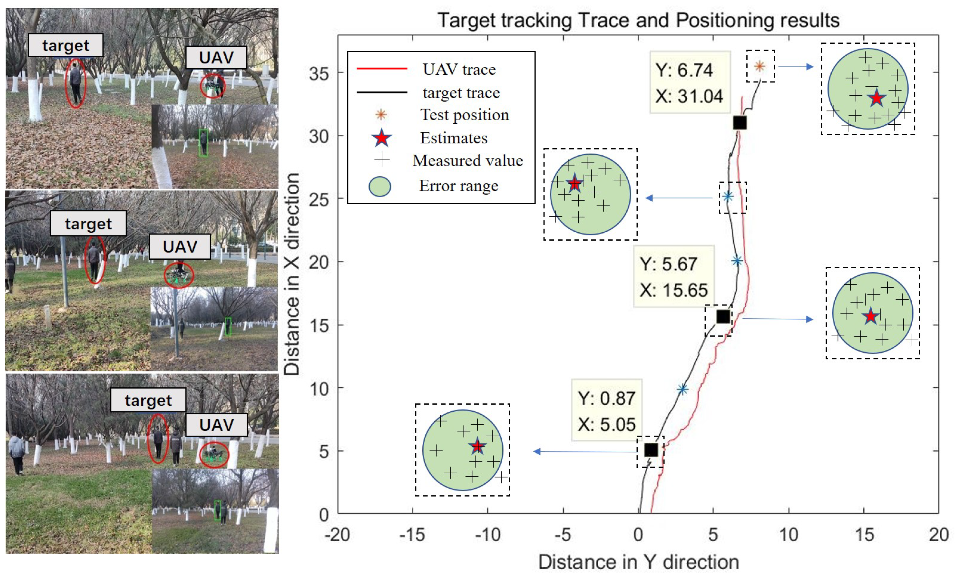
4.3. Positioning and Path Planning Experiment

In order to ensure the continuity of the UAV tracking task, we need to verify the accuracy of the positioning method described in Section 2.3 to ensure that the UAV target positioning can provide local path waypoints. The experimental environment is an unstructured outdoor scene with dense trees, shrubs, and pedestrians. The specific personnel target walks along the preset track in the forest, and there are seven test points on the track in turn. In the process of tracking a specific target, the UAV randomly encounters the influence of tree occlusion, interference from two similar pedestrian targets, and changes in light intensity. The UAV uses visual positioning to take off from ( 0 , 0 ) point to track, locate and plan the path of the target.
After the UAV lands, we analyze and calculate the data through the ROS data package recorded during the flight, and take the average of the positioning data less than 0.5 m around the seven test points as the estimation data. As shown in Table 4, according to the data of our localizer solution, the error of each point is about 10%, which verifies the effectiveness of the location algorithm.
At the same time, we tested the path-planning algorithm in a complex environment. Table 5 shows the parameter settings of the path planning algorithm described in Section 3.
The process of the UAV moving target tracking system is as follows. First, the image collected by the sensor is input to the tracking module to obtain the position of the target in the image. Then the target is located, and the location information is sent to the UAV for path planning to guide the UAV for flight tracking. In the process of UAV flight tracking, the distance between the UAV and the target is used to determine whether to carry out flight tracking. If the distance is greater than 3 m, the flight tracking will be carried out; otherwise, the tracking will be stopped. Figure 14 shows that when the UAV tracks a specific target, the nose can adaptively adjust the yaw angle according to the path planning algorithm to adapt to the human tracking task so that the target can appear in the center of the camera’s field of view as much as possible under the angle constraint. Figure 14 also shows a path suitable for tracking tasks planned by the UAV platform in a complex jungle environment. The black line is the real trace of the moving target, and the red line is the motion trace of the UAV. From the first perspective, we can see that the proposed tracking method can track the target robustly. In the third perspective, according to the target location in the local world coordinate system, the UAV can stably track and fly towards the target while avoiding obstacles, which verifies the reliability of the algorithm.

5. Discussion

In this paper, a small unmanned aerial vehicle (UAV) platform in an outdoor unstructured environment for specific target tracking and location and path planning system is proposed. DTE-tracker module and target capture mechanism are designed for automatic target tracking, which improves the accuracy and robustness of target tracking in complex environments such as occlusion, light change, similar target interference, etc. The method based on an RGB-D camera is used to calculate the three-dimensional space position from the two-dimensional target in the image to obtain the location position, which provides the track point for the subsequent path planning. The DWA local path planning algorithm based on the human-following task is designed to adaptively adjust the tracking angle, which verifies the reliability of the algorithm in complex environments. In future work, we will improve the accuracy and robustness of the tracking algorithm and path planning algorithm, as well as the real-time performance of the embedded system to achieve the tracking of fast-moving targets.

Author Contributions

Conceptualization, H.L., M.Y., C.Z.; methodology, H.L., M.Y., Y.L., L.D.; software, M.Y., Y.L., L.D.; validation, Y.L., L.D.; formal analysis, H.L., M.Y.; investigation, H.L., M.Y., Y.L., L.D.; resources, C.Z.; data curation, M.Y., Y.L., L.D.; writing—original draft preparation, H.L., M.Y., Y.L., L.D., C.Z.; writing—review and editing, H.L., M.Y., C.Z.; visualization, M.Y., Y.L.; supervision, C.Z.; project administration, C.Z.; funding acquisition, C.Z. All authors have read and agreed to the published version of the manuscript.

Funding

This research was funded by the National Natural Science Foundation of China (NO. 62073264) and Key Research and Development Project of Shaanxi Province (NO. 2021ZDLGY01-01).

Data Availability Statement

Not applicable.

Conflicts of Interest

The authors declare no conflict of interest. And the funders had no role in the design of the study; in the collection, analyses, or interpretation of data; in the writing of the manuscript; or in the decision to publish the results.

References

  1. Sadykova, D.; Pernebayeva, D.; Bagheri, M.; James, A. IN-YOLO: Real-time detection of outdoor high voltage insulators using UAV imaging. IEEE Trans. Power Deliv. 2019, 35, 1599–1601. [Google Scholar] [CrossRef]
  2. Zhang, Y.; Yuan, X.; Li, W.; Chen, S. Automatic power line inspection using UAV images. Remote Sens. 2017, 9, 824. [Google Scholar] [CrossRef] [Green Version]
  3. Chen, H.; Lan, Y.; Fritz, B.K.; Hoffmann, C.; Liu, S. Review of agricultural spraying technologies for plant protection using unmanned aerial vehicle (UAV). Int. J. Agric. Biol. Eng. 2021, 14, 38–49. [Google Scholar] [CrossRef]
  4. Jiang, N.; Wang, K.; Peng, X.; Yu, X.; Wang, Q.; Xing, J.; Li, G.; Zhao, J.; Guo, G.; Han, Z. Anti-UAV: A large multi-modal benchmark for UAV tracking. arXiv 2021, arXiv:2101.08466. [Google Scholar]
  5. Blösch, M.; Weiss, S.; Scaramuzza, D.; Siegwart, R. Vision based MAV navigation in unknown and unstructured environments. In Proceedings of the IEEE International Conference on Robotics and Automation, Anchorage, AK, USA, 3–7 May 2010; pp. 21–28. [Google Scholar]
  6. Liu, C.; Song, Y.; Guo, Y.; Xu, B.; Zhang, Y.; Li, L.; Li, Z. Vision information and laser module based UAV target tracking. In Proceedings of the IECON 2019-45th Annual Conference of the IEEE Industrial Electronics Society, Lisbon, Portugal, 14–17 October 2019; Volume 1. [Google Scholar]
  7. Zhao, X.; Pu, F.; Wang, Z.; Chen, H.; Xu, Z. Detection, tracking, and geolocation of moving vehicle from uav using monocular camera. IEEE Access 2019, 7, 101160–101170. [Google Scholar] [CrossRef]
  8. Quintero, S.A.P.; Hespanha, J.P. Vision-based target tracking with a small UAV: Optimization-based control strategies. Control Eng. Pract. 2014, 32, 28–42. [Google Scholar] [CrossRef] [Green Version]
  9. Liu, Y.; Wang, Q.; Hu, H.; He, Y. A novel real-time moving target tracking and path planning system for a quadrotor UAV in unknown unstructured outdoor scenes. IEEE Trans. Syst. Man Cybern. Syst. 2019, 49, 2362–2372. [Google Scholar] [CrossRef] [Green Version]
  10. Giusti, A.; Guzzi, J.; Ciresan, D.C.; He, F.-L.; Rodríguez, J.P.; Fontana, F.; Faessler, M.; Forster, C.; Schmidhuber, J.; Di Caro, G.; et al. A machine learning approach to visual perception of forest trails for mobile robots. IEEE Robot. Autom. Lett. 2016, 1, 661–667. [Google Scholar] [CrossRef] [Green Version]
  11. Voigtlaender, P.; Luiten, J.; Torr, P.H.S.; Leibe, B. Siam r-cnn: Visual tracking by re-detection. In Proceedings of the IEEE/CVF Conference on Computer Vision and Pattern Recognition, Seattle, WA, USA, 13–19 June 2020; pp. 6578–6588. [Google Scholar]
  12. Ultralytics-Yolov5. Available online: https://github.com/ultralytics/yolov5 (accessed on 1 January 2021).
  13. Zagoruyko, S.; Komodakis, N. Learning to compare image patches via convolutional neural networks. In Proceedings of the IEEE Conference on Computer Vision and Pattern Recognition, Boston, MA, USA, 7–12 June 2015. [Google Scholar]
  14. Li, B.; Yan, J.; Wu, W.; Zhu, Z.; Hu, X. High performance visual tracking with siamese region proposal network. In Proceedings of the IEEE Conference on Computer Vision and Pattern Recognition, Salt Lake City, UT, USA, 18–23 June 2018. [Google Scholar]
  15. Redmon, J.; Farhadi, A. Yolov3: An incremental improvement. arXiv 2018, arXiv:1804.02767. [Google Scholar]
  16. Bochkovskiy, A.; Wang, C.Y.; Liao, H.Y.M. Yolov4: Optimal speed and accuracy of object detection. arXiv 2020, arXiv:2004.10934. [Google Scholar]
  17. Ma, N.; Zhang, X.; Zheng, H.-T.; Sun, J. Shufflenet v2: Practical guidelines for efficient cnn architecture design. In Proceedings of the European Conference on Computer Vision (ECCV), Munich, Germany, 8–14 September 2018; pp. 116–131. [Google Scholar]
  18. Krizhevsky, A.; Sutskever, I.; Hinton, G.E. Imagenet classification with deep convolutional neural networks. Commun. ACM 2017, 60, 84–90. [Google Scholar] [CrossRef] [Green Version]
  19. Fox, D.; Burgard, W.; Thrun, S. The dynamic window approach to collision avoidance. IEEE Robot. Autom. Mag. 1997, 4, 23–33. [Google Scholar] [CrossRef] [Green Version]
  20. Han, D. Research on Human Tracking Technology of Mobile Robot Based on Visual Object Tracking; Zhejiang University: Hangzhou, China, 2021. [Google Scholar]
  21. Yan, B.; Zhao, H.; Wang, D.; Lu, H.; Yang, X. ‘Skimming-Perusal’ Tracking: A Framework for Real-Time and Robust Long-Term Tracking. In Proceedings of the IEEE/CVF International Conference on Computer Vision, Seoul, Republic of Korea, 27 October–2 November 2019; pp. 2385–2393. [Google Scholar]
  22. Zhu, Z.; Wang, Q.; Li, B.; Wu, W.; Yan, J.; Hu, W. Distractor-aware siamese networks for visual object tracking. In Proceedings of the European Conference on Computer Vision (ECCV), Munich, Germany, 8–14 September 2018; pp. 101–117. [Google Scholar]
Figure 1. Dynamic Target Tracking and Control Framework of UAV.
Electronics 12 01078 g001
Figure 2. DTE-tracker design.
Electronics 12 01078 g002
Figure 3. Comparison of detection and tracking results. (a) the result of the detection. (b) the result of tracking.
Electronics 12 01078 g003
Figure 4. The variation of tracking confidence α . (a) normal. (b) short-term occlusion. (c) failed.
Electronics 12 01078 g004
Figure 5. The sliding window method.
Electronics 12 01078 g005
Figure 6. Schematic diagram of coordinate system. (a) Pixel coordinate system. (b) Camera coordinate system.
Electronics 12 01078 g006
Figure 7. Schematic diagram of coordinate conversion.
Electronics 12 01078 g007
Figure 8. Schematic Diagram of Relative Position of Camera and Tracking Target.
Electronics 12 01078 g008
Figure 9. Relationship of Angular velocity and angle θ .
Electronics 12 01078 g009
Figure 10. Schematic Diagram of Velocity Sampling and Forward Simulation.
Electronics 12 01078 g010
Figure 11. Four-rotor UAV experimental platform.
Electronics 12 01078 g011
Figure 12. Some running results of the DTE-tracker algorithm (from top to bottom are sequence 1–4).
Electronics 12 01078 g012
Figure 13. Comparison of SiamRPN and DTE-tracker tracking results. (a) The tracking effect of SiamRPN. (b) The tracking effect of DTE-tracker.
Electronics 12 01078 g013
Figure 14. Target tracking Trace and Position results.
Electronics 12 01078 g014
Table 1. The average time cost of each module on Xavier NX.
ModuleDetectorTrackerExaminerDTE-Tracker
average time cost (ms/frame)42.835.618.351.7
Table 2. Tracking result statistics.
Short Time OcclusionThe Target Disappears
Total number of challenges3417
Judge success times3117
Judge the success rate91.2%100%
Number of re-tracking15
Re-tracking success rate88.2%
Table 3. Comparison between this method and mainstream methods.
SPLT [21]DaSiamRPN [22]SiamRPNDTE-Tracker
The success rate73.0%70.8%61.1%72.3%
FPS2.123.731.225.1
Table 4. Experiment Result of seven path points.
NumberGround TruthEstimatesMean ErrorProportion
1(5.13, 0.81)(5.05, 0.87)0.100.91
2(9.80, 2.84)(9.85, 2.93)0.110.86
3(15.36, 5.55)(15.65, 5.67)0.310.89
4(20.16, 6.87)(20.09, 6.58)0.290.94
5(24.94, 6.25)(25.18, 5.99)0.340.93
6(31.38, 6.53)(31.04, 6.74)0.390.88
7(35.35, 8.22)(35.64, 8.43)0.360.96
Table 5. Path planning parameter setting.
Parameter NameParameter ValueParameter NameParameter Value
Sampling time0.2 s D T 1.0 s
v m a x 0.8 m/s v m i n −0.3 m/s
ω m a x 0.5 rad/s ω m i n 0.03 rad/s
a x m a x 0.5 m/s 2 a y m a x 0.5 m/s 2
β m a x 0.3 rad/s 2
Disclaimer/Publisher’s Note: The statements, opinions and data contained in all publications are solely those of the individual author(s) and contributor(s) and not of MDPI and/or the editor(s). MDPI and/or the editor(s) disclaim responsibility for any injury to people or property resulting from any ideas, methods, instructions or products referred to in the content.

