1. Introduction
With the booming development of the unmanned aerial vehicles (UAV), UAVs have been widely used in agriculture, inspection, security, rescue, and other fields [
1]. Currently, using a single UAV for executing tasks is a typical practice [
2]. However, when the task area is large, the UAV requires several round-trips or multiple transitions to fully cover the entire task area, which is time-consuming and inefficient. In some places, the terrain factors also limit the communication between the UAV and the ground control station. Since the UAV cannot reach the target area, the task may not be completed.
Recently, the flying ad hoc network (FANET) has attracted great attention, because it has significant advantages compared to the single UAV technique in the face of the above difficulties. The FANET is a dynamic ad hoc network system with an arbitrary, temporary, and autonomous network topology [
3]. As a network node of FANET, each UAV is equipped with FANET communication modules (including routing and message forwarding functions), and can form any network topology through wireless connections [
4]. As a result, in this network, the UAV can be used as a task node or a relay node. When being regarded as the task node, the UAV executes the task when under the control of the ground control station or other UAVs. If being used as the relay node [
5], the UAV participates in routing maintenance and packet forwarding according to the routing policy and routing table of the network. Multiple UAVs work together to sense the task environments, through the FANET technique, which shares the information between multiple UAVs. The UAVs can also complete the task of the large scale region monitoring when line-of-sight communications are blocked [
6], further reducing the dependence of the UAV swarm system on individuals. Because the individual UAV leaves or joins the system, the whole swarm system still has certain integrity and can continue to perform tasks.
For FANETs, the increasing demand of routing in the field of communication is the most important subject currently. It is a challenge for a routing protocol to calculate the best optimal path in any network. Because of the dynamic spatial and temporal mobility of FANET nodes, the performance and efficiency of the routing protocol become very critical. One study [
7] presents a novel routing protocol for FANET using modified AntHocNet. The protocol has better dependability than most current legacy best path selection techniques.
Additionally, to exploit the advantages of UAV swarm systems, the number of nodes, the distribution range, and the network scale of FANET need to be enlarged. The use of an algorithm [
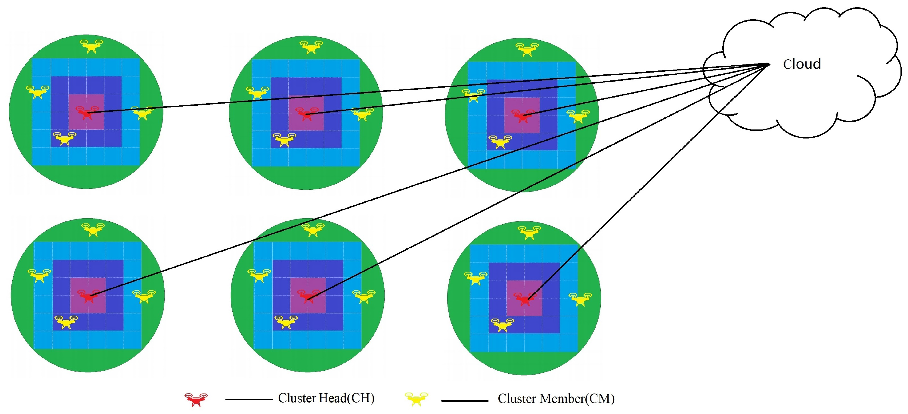
8] is an effective method to improve the performance of FANET. This clustering algorithm can manage network energy consumption effectively and prolong the whole network life. By applying the cluster algorithm, the whole UAV network is divided into several smaller clusters. A cluster consists of a cluster head (CH) and several cluster members (CMs). The CH needs to be selected reasonably, as it is used to manage and maintain the cluster to which it belongs [
9]. Compared with the planar structure, the clustered network structure can reduce the influence of local topological changes on the whole network [
10]. In the process of route calculation and generation, only partial nodes are required to participate in the clustering algorithm, effectively reducing the cost of routing and control. In addition, the cluster network structure can improve the network scalability.
Since the CH is important for a cluster, it is necessary to design a reasonable cluster head selection strategy, to guarantee the stability of the clustering structure. Moreover, because the CH needs to receive, process and send a lot of information, the energy consumption of the CH is very heavy, which is fatal to the lifetime of the whole FANET. Therefore, reducing the energy consumption of the CH should be considered. However, most existing clustering algorithms such as [
7,
9] do not simultaneously optimize the cluster number, the CH selection, the communication resource allocation, and the cluster structure stability. Some algorithms such as [
8] even randomly assign the CHs and the cluster number, degrading the stability of the whole network. Therefore, it is necessary to design a scheme to overcome the shortcomings of the above algorithms and improve the overrall performance of FANETs.
To address the related issues, this paper proposes a dynamic transmission power of the cluster heads based clustering (DTPCH-C) scheme, developed using the new K-means algorithm. Different from the traditional K-means algorithm, the clustering process is optimized in the new K-means algorithm. The number of clusters and the selection of CHs are optimized. Firstly, in the clustering process, to reduce the clustering overhead, the primary number of clusters needs to be optimally determined for the initial clustering center selection. Subsequently, according to the CH election strategy, the UAV node with the highest fitness value is selected as the CH in a cluster, while the remainders are CMs, which can improve the reliability of FANETs. We also design a moving prediction model-based dynamic transmission strategy to allocate the power of the CH. By predicting the distance between cluster heads and CMs, the transmission power of the CHs is adjusted, so as to reduce the energy consumption of CHs and enhance the life of the cluster network.
The key contributions of this paper are summarized as follows:
A novel clustering scheme with dynamic transmission power of CHs is presented for FANETs to improve reliability and lifetime of FANETs. The proposed DTPCH-C scheme is realized by initialing the cluster, reducing the energy consumption of the CHs, selecting CHs and maintaining clusters.
The variable transmission power mechanism of the CH is proposed. Using grid mode-based transmission power adjustment and movement prediction, the CH can flexibly adjust its transmitting power according to its distance to different CMs, which saves energy and improves the lifetime of FANETs.
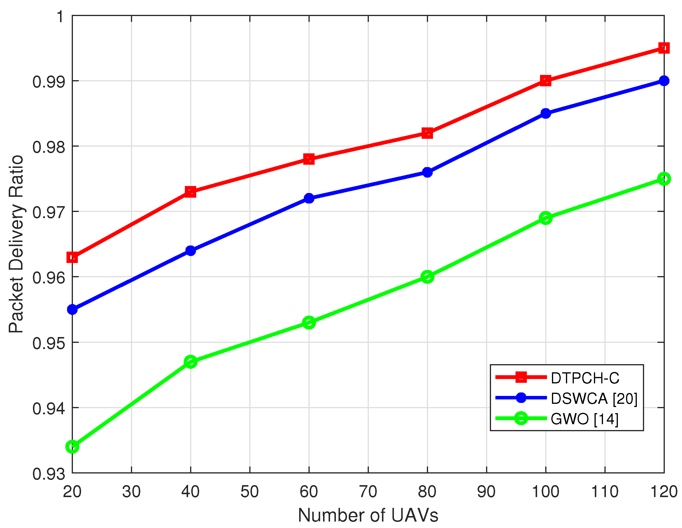
Meanwhile, we propose a weighted summation-based CH selection algorithm, where the adaptive node degree, the remaining energy ratio and the distance between nodes are all involved in the selection criteria. The UAV node with the maximum weight is selected as the CH. As a result, the probability of the most appropriate node becoming a CH is improved so that the packet delivery ratio (PDR) grows. Therefore, the reliability of the network is enhanced.
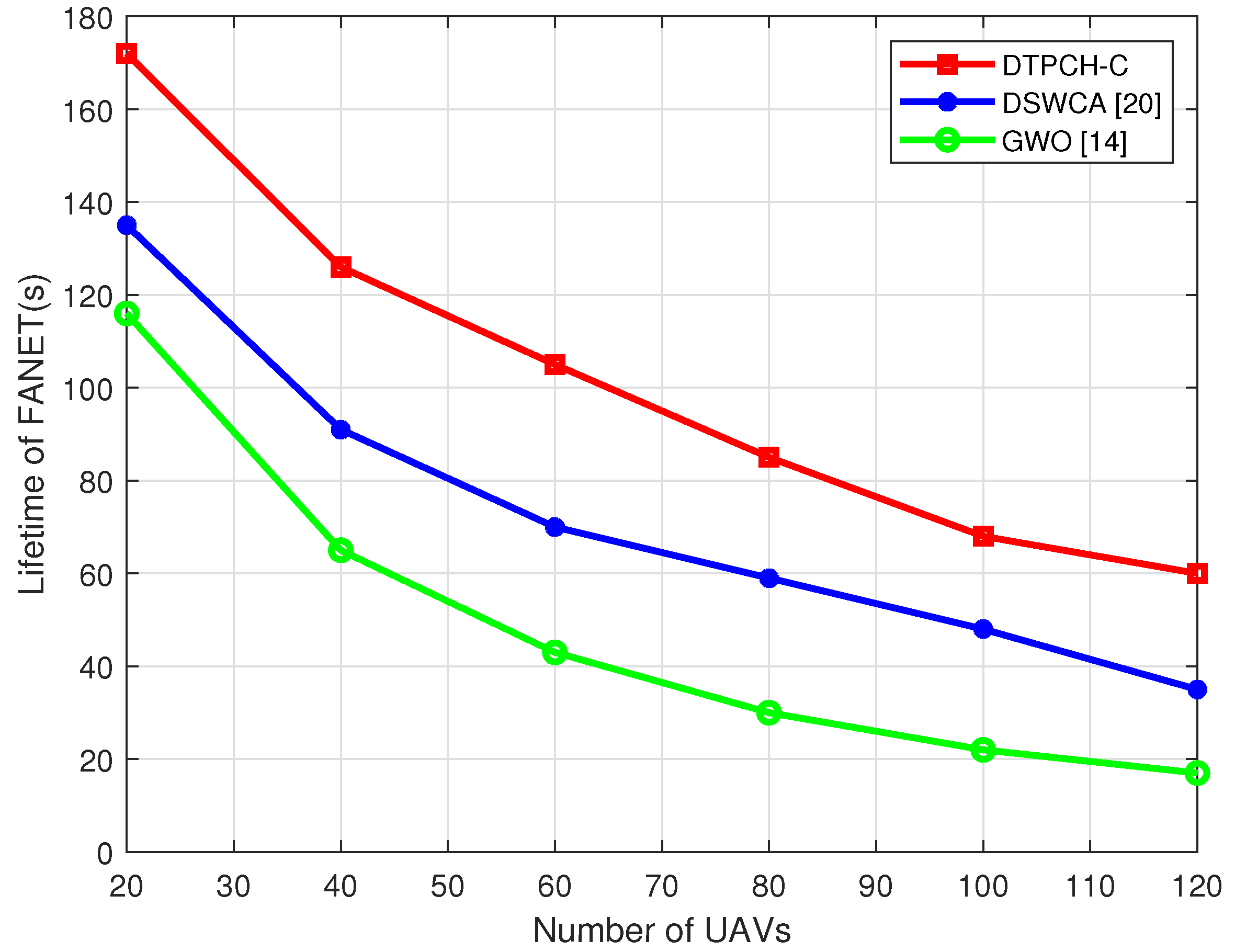
According to the simulation results, the proposed DTPCH-C scheme has more advantages than the existing clustering methods in terms of reliability, lifetime and energy consumption.
The rest of this paper is organized as follows:
Section 2 describes the background about FANETs and related works. The system model is introduced in
Section 3. In
Section 4, the proposed DTPCH-C scheme is presented in detail. In
Section 5, we compare the performance of the DTPCH-C algorithm with the other two algorithms and draw the conclusion that the performances of the DTPCH-C is better than the others. In
Section 6, we summarize of the whole paper.
2. Background and Related Works
The lowest identification (LID) clustering algorithm was put forward by Gerla et al. [
11]. This algorithm is based on the least node ID cluster head election. The node is assigned a random ID and selects the neighbor nodes. The smallest ID node is the cluster head. The cluster structure maintenance method is based on the ID value. The LID algorithm has low computational complexity, but easily leads to an unbalanced load and has fixed cluster head selection. To improve the rationality of cluster head selection and enhance the adaptability of the scene, Wang et al. proposed a weighted clustering algorithm (WCA) [
12], which comprehensively considers the node degree, distance, and mobility. In the WCA, malicious nodes can be selected as CHs in the process of clustering, which in turn accompanies some security issues. For this reason, some researchers also propose improved or variant WCAs.
According to the energy characteristics of the nodes, a series of clustering algorithms based on the number of nodes are presented. For example, the low-power adaptive clustering algorithm (Leach) selects CHs through random probability and changes CHs at certain intervals to balance the load in terms of the network energy and extend the network life. The disadvantage of Leach is that only the remaining energy of the node is considered, and the performance of this method is poor in the actual application process. Moreover, since CHs are assumed to be able to communicate with the base station, the method is not suitable for large-scale networks.
Some researchers are inspired by biological behaviors and apply these for the clustering the FANETs. In [
13], an ant colony optimization (ACO) clustering scheme is proposed for optimal clustering and data transmission in the FANETs. CHs are vertices in the search space, and each round provides the set of CHs from specific environments. The algorithm uses two objective functions to evaluate the fitness value of each cycle, namely, the Euclidean distance and the delta difference. In [
14], the grey wolf optimization (GWO) algorithm is proposed for an energy-efficient routing protocol. This algorithm has the advantage of high robustness and accuracy, and its convergence rate is faster than similar algorithms. However, the disadvantage of this algorithm is that the convergence rate is too slow in the late stage, and it is easy to fall into the local optimal solution.
In FANETs, maintaining network connectivity is an important consideration when designing UAV clustering algorithms. Lu et al. [
15] designed a connectivity degree-based high connectivity clustering (HCC) algorithm to implement UAV clustering. In the HCC algorithm, the node with the largest number of neighbors is first selected as the CH, and then a limited number of clusters is generated. Due to the movement of the UAV (i.e., the node), the number of neighbor nodes of each node may change, which means that the cluster head needs to be re-selected accordingly. Due to the frequent selection of cluster heads and multiple reconnections of nodes, the HCC algorithm has poor adaptability and reduced throughput for dynamic UAV nodes.
Many researchers also combine some mature clustering algorithms with the characteristics of FANETs to design different UAV clustering algorithms [
16]. The study [
17] proposes a K-means-based (KMB) UAV clustering algorithm for the cluster head selection, and added a mobile agent to collect and fuse the data in the cluster. This algorithm overcomes the shortcomings of traditional K-means algorithm, and has the advantages, such as avoiding local optima, high precision solution and simple operations. The authors of [
18] studied an evenly split ring-based UAV clustering (SRC) algorithm by applying fuzzy logic. In this algorithm, the energy of the node, the node degree, node-to-node distance, the ring width, and the staring energy parameters are utilized as the input of fuzzy rules. Then, the optimal number of clusters can be obtained. The study [
19] proposes an energy-efficient swarm-intelligence-based clustering (SIC) algorithm, in which the particle fitness function is exploited for intercluster distance, intracluster distance, residual energy, and geographic location. For energy-efficient clustering, cluster heads are selected based on improved particle optimization. In [
20], the authors propose a dynamic scale UAV weighted clustering algorithm (DSWCA). By determining the optimal, maximum and minimum values of the cluster scale and make the cluster scale dynamic, the algorithm can achieve superior performance in network load balance.
Table 1 summarizes the performance positioning of the discussed clustering schemes in FANETs. Compared with other algorithms, the proposed DTPCH-C scheme comprehensively considers the reliability, energy efficiency, and PDR in the FANET.
4. Proposed Approach
In this section, we will introduce the DTPCH-C algorithm in detail considering four aspects: (1)
Section 4.1 introduces the method used to calculate the optimal cluster head number; (2) in
Section 4.2, the cluster head election strategy is proposed; (3) in
Section 4.3,
Section 4.4,
Section 4.5 and
Section 4.6, the principle of the scheme with the dynamic transmission power of CHs is introduced in detail; and (4)
Section 4.7 describes the cluster maintenance process.
4.1. Calculation of Optimal Cluster Head Number
In the traditional K-means algorithm, the primary number of clusters is set randomly in the clustering process. If the number of clusters is not set properly, the performance of FANETs deteriorates. When the number of clusters is small, the energy consumption for communication will increase, but if the number of clusters is large, the advantages brought by UAV clustering will be weakened. In the clustering process, to reduce the clustering overhead and utilize the bandwidth efficiently, the primary number of clusters needs to be optimally determined for the initial clustering center selection. According to [
22], the throughput of a single node in the FANET can be expressed as
where
N is the number of network nodes,
B is the communication bandwidth, and
is the asymptotically tight bound. After clustering, we can obtain the throughput of each CM, as given by
where
is the bandwidth within the cluster and
k is the number of clusters. In addition, the throughput of each CH is
where
is the bandwidth between clusters. It assumes that the network traffic is uniformly distributed. Because of the throughput balance between the inter-cluster and the intra-cluster communications the proportion of
used for traffic in/out to other clusters is
, and the portion should be smaller or equal to
[
23], i.e.,
When
reaches the maximum throughput, namely, when inequality (6) holds, the primary number of clusters
n is obtained as
If
N is large enough, the optimal number of clusters
n is approximated to
Based on the optimal number
n, K-means clustering algorithm can be used to divide
N UAVs into clusters. The pseudocode of the K-means clustering algorithm is listed in Algorithm 1.
| Algorithm 1 K-means Clustering Algorithm |
- Input:
The optimal number of clusters n, The UAV nodes are modeled as a point set S = {, , ..., } - Output:
/*Initialization*/ -
randomly select n initial clustering centers uniformly from S - 1:
Repeat - 2:
calculate the distance from each node to each cluster center, and the node is assigned to the nearest cluster - 3:
after all nodes are allocated, the centroids of n clusters are recalculated - 4:
until centroids remain unchanged - 5:
return clusters set = {, , …, }
|
4.2. Cluster Head Election Strategy
In the traditional K-means clustering algorithm, the election of CHs is inappropriate. To improve the performance and lifetime of FANETs, it is important to select the appropriate cluster head of each cluster. In a cluster, an appropriate cluster head should meet the following criteria: (1) in order to improve the success rate of information exchange between cluster head and cluster members and the utilization of network bandwidth resources, we should choose the node with high adaptive node degree; (2) in order to improve the lifetime of FANETs and avoid data transmission failure due to cluster head death, we should choose the node that has more energy left; (3) to ensure that the topology of the network does not change too much after each round of cluster maintenance, the distance between the node i and its cluster head should not be far.
To elect the CH satisfying the above conditions, in this subsection, we will focus on the optimization of the CH election, where the adaptive node degree, node remaining energy, and the Euclidean distance between nodes are jointly considered.
4.2.1. Adaptive Node Degree
In order to improve the utilization of network bandwidth resources, the number of neighbor nodes around the CH is controlled. The adaptive node degree [
12] is used in this paper to avoid network congestion. The degree is positively correlated to the probability of a node being selected as the CH. In the network, each node obtains the node degree of itself by exchanging HELLO messages. The node degree of node
i is defined as
where
is the distance between the node
i and the node
j, and
r is the node communication radius. The adaptive node degree difference is defined as
where
n is the optimal number of clusters determined by (8). After normalization, the adaptive node degree of node
i is
4.2.2. Node Remaining Energy
The remaining energy of the UAV node is also an important election criterion. If a UAV node has low energy, it is less likely to become the cluster head. This is because the remaining energy of this node may not be enough to maintain its continuous work, thereby affecting the communication of the whole network. The residual energy ratio
of node
i can be expressed as
where
is the total energy of node
i.
is the total energy consumption of node
i, which is written as
where
is the energy consumed by sending message of node
i.
is the energy consumed by receiving message of node
i.
is the flying consumption of node
i, which is calculated as
where
is the flying time of UAV. is the mass of UAV, and g are the air density and earth gravity, respectively. is the number of wings. is the radius of wings.
4.2.3. Euclidean Distance from the Node to the Cluster Head
The Euclidean distance between the node
i and its cluster head is considered. Shortening the distance can increase the probability that the node
i becomes the next cluster head, which is conducive to maintaining the reliability of the entire network structure. We use the symbol
to represent the distance index of this node.
can be expressed as
where
and
are the horizontal and vertical coordinates of the node
i; and
and
are the horizontal and vertical coordinates of the cluster head. The distance is normalized by
4.2.4. Weighted Metric Criterion
Based the above
,
and
, the updated criteria of cluster head measurement weight is expressed as
where
,
,
are the weights of the three factors, and
. Moreover, these weights are defined on the interval [0, 1]. The specific proportion coefficient’s value can be assigned according to task requirements. Through this criterion, the randomness of cluster head election and the defect of falling into local optimal solution can be avoided effectively.
Based on the definition of the three factors, the cluster head selection is proposed, of which the pseudocode is listed in Algorithm 2.
| Algorithm 2 Cluster Head Selection Algorithm. |
- Input:
The optimal number of clusters n, clusters set = {, , …, } - Output:
Every node gets information about its adaptive node degree and distance by -
HELLO message sent by the neighbor nodes - 1:
Every node i calculates the weight by the Equation ( 19) - 2:
The node with the largest value of R in each cluster is set as the cluster head and broadcasts its message within the cluster - 3:
return, , …,
|
4.3. Analysis of Cluster Head Transmission Power
The motion states of UAVs include the position, speed, direction, and so on. To adapt the clustering algorithm to the highly dynamic characteristics of nodes, the motion characteristics of UAVs was analyzed. Assume that UAVs can obtain high-precision positioning information in real time through the Global Positioning System(GPS). In the system, each UAV can obtain the specific location information according to its positioning equipment, and transmit the location information through the HELLO message broadcast by the system. The node within the receiving range receives the information to obtain the geographical location information of the neighboring node, so that the neighbor list can be maintained. After the UAVs are clustered, the cluster head can find the distance between the cluster members and itself according to its neighbor list.
According to the distance between the cluster members, the cluster head can adjust the transmitting power by reducing the transmitting power when transmitting information to the node within a short distance and increasing the transmitting power when sending data packets to the node within the maximum communication range. The ideal communication loss (free space) [
24] between UAVs can be expressed as
where
d is the propagation distance and
f is the working frequency. In practical applications, because wireless communication is affected by various external factors, such as atmosphere, barriers, multipath, etc., the
is high. By plugging the reference value into (20), the total transmission loss can be calculated [
25].
The transmitting power of the cluster head should not be less than the sum of the wireless transmission loss and the reception sensitivity of the UAV. Considering that the working frequency and reception sensitivity of UAVs are constant, the relationship between the transmitting power and propagation distance can be obtained, as given by
where
is the transmitting loss caused by the reception sensitivity, and
is the transmitting loss due to the multipath fading, atmospheric loss, and so on.
4.4. Grid Mode for Cluster Head Transmission Power Adjustment
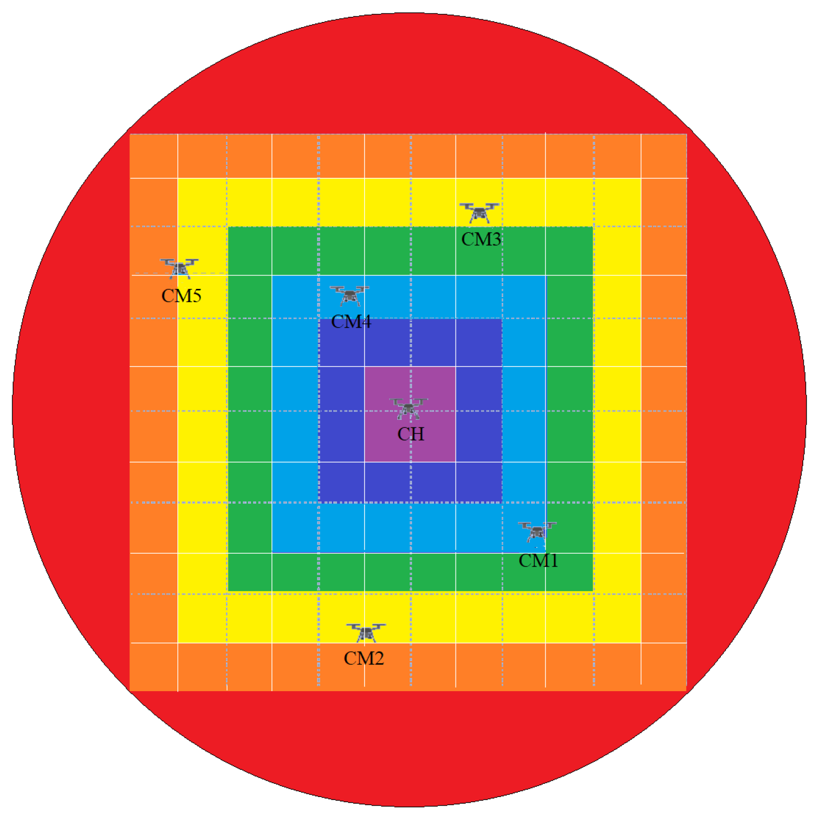
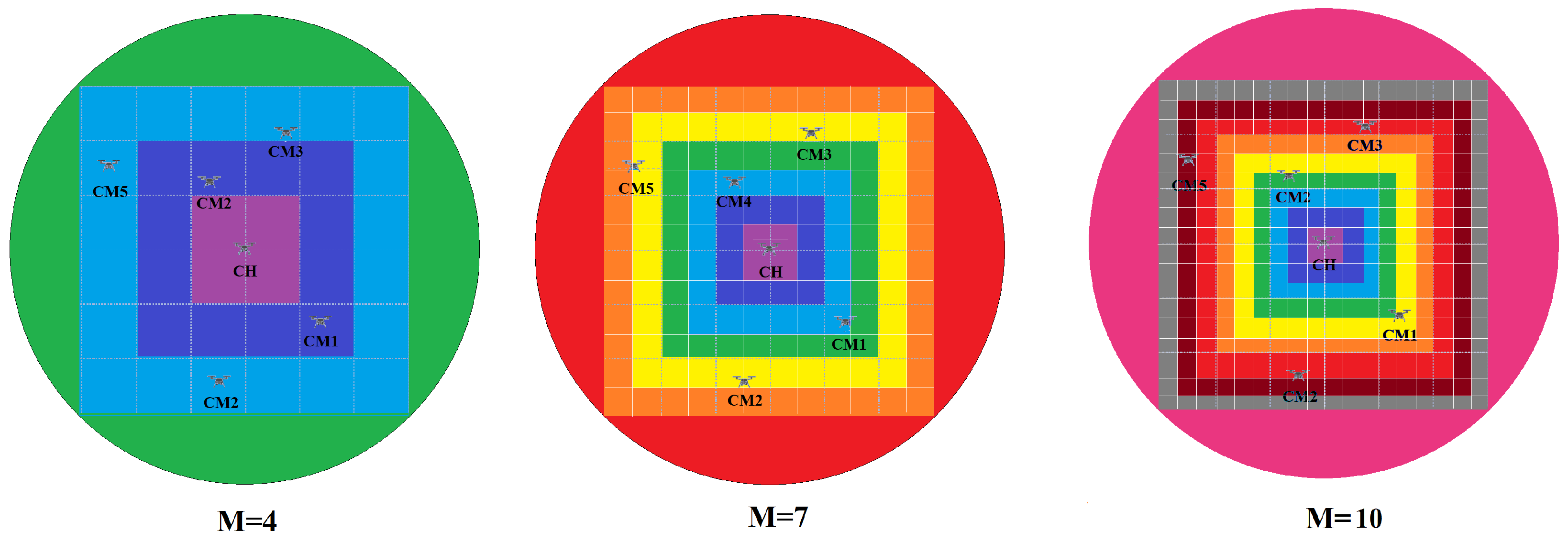
Since the UAV moves at a high speed, if the transmission power of the cluster head is changed due to the distance between the UAVs, the cluster head needs to calculate the required transmission power all the time, wasting resources. We designed a grid mode-based transmission power adjustment method, as shown in
Figure 3. The transmission power of cluster heads was set discretely, and each grid has different colors corresponding to the different sizes of transmission power. The advantages of this design are: (1) avoiding the frequent change in transmitting power and thus reducing the energy consumption caused by its internal calculation; and (2) predicting the moving trajectory, so that the cluster head can analyze the trend of cluster members and accurately adjust its transmitting power.
4.5. Prediction of Cluster Member Movement
4.5.1. Problem Description
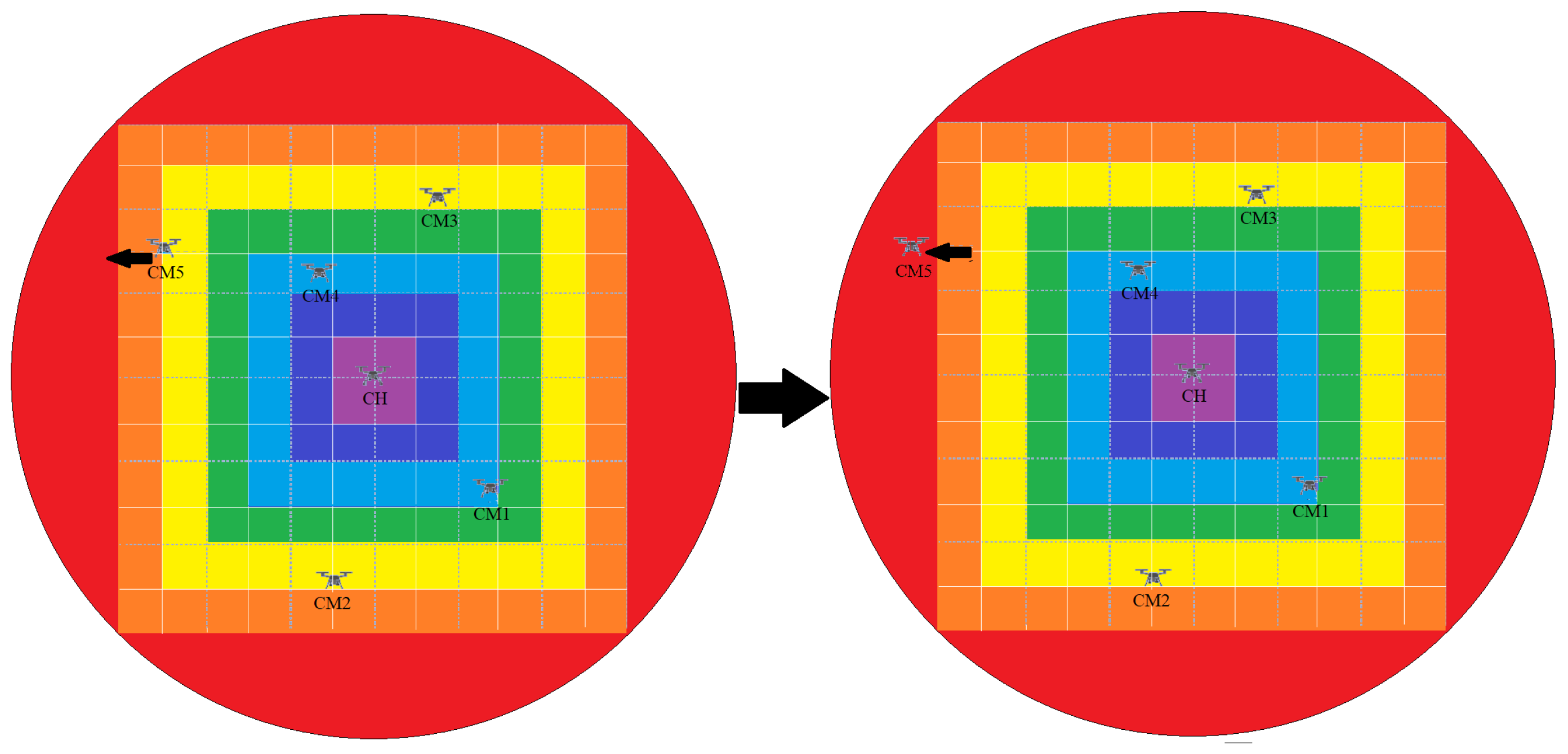
Because UAVs are not always relatively static, cluster heads need to adjust their transmitting power in real-time according to the distance between the UAVs and cluster members. This can avoid resource waste caused by excessive transmitting power or the failure of cluster members to receive information due to the CH’s insufficient transmitting power, as shown in
Figure 4. A movement prediction mechanism is set up in this paper, which is used to predict the grid position of its members in the next transmission cycle and adjust the transmission power in time.
4.5.2. Mobility Model
In the FANET, the node movement is regular and cannot be described by a completely random entity movement model. The group mobility is also taken into account. We applied the Gauss-Markov model [
26] to represent the movement trajectory of nodes, which overcomes the defect of the sudden stop and turn. So this model is more consistent with reality.
For the convenience of analysis, this paper assumes that the UAV node can obtain its position and speed information through GPS. Since we set the UAVs to fly at the same altitude, so we only concentrate on the x and y axes of the coordinate system. Moreover, the CH is regarded as static, and the coordinate system is set with it as the center to analyze the node movement.
Theory: When calculating the new speed and direction, each node has an initial speed and direction, and an average speed and direction. In each time step, we calculated the new speed and direction at the next moment, and repeated the operation.
Define:
Q is a square with sides of length
S, which represents the moving region of the node, where
S is no more than the communication diameter of the node. It was assumed that all UAVs have a velocity with the same direction and magnitude at the beginning of the experiment. We removed this velocity and just considered the relative motion of each UAV so that the movement of UAVs was easier to analyze. At the beginning,
n nodes are evenly distributed in the set area. Additionally, at the same time, UAVs will start to move according to the Gauss-Markov model, while being restricted in the area
Q based on the actual situation. Since the UAV is regarded as a point and the scale of FANET is not particularly large, the case of collision between the UAVs is not considered.
U = (
,
…
), represents the collection of nodes,
is the
i-th node,
U;
represents the position of the
i-th node;
represents the speed of the
i-th node; and
represents the angle between velocity reversal and the X-axis. The time interval of HELLO message exchange is discretized, i.e.,
, where
is time step,
k is the number of time segments. At time
the CH obtains the CM
′s velocity
, direction angle
and the position
from HELLO message exchange. Hence, the CM
′s velocity and direction angle at time
can be calculated as
where
is the relevant memory parameter, denoting the correlation between the current time slot and the previous time slot in speed and direction, and
. The strength of the correlation can be changed by adjusting the value of
;
,
m represents the
m-th time slot; and
and
represent the average velocity and the average directional angle over the period. Therefore, according to (22), we can predict the velocity and direction angle of the node at any time in the periodic interval, and the position of CM
at
can be obtained by:
4.6. Link Expiration Time
Using the movement prediction model, the CH can successfully predict the location of cluster members at the next instance. To adjust the transmitting power quickly and conveniently, the CH calculates the link connection time when the transmitting power needs to be changed by calculating the link connection time. This can avoid the resource waste caused by the frequent calculation of the CH.
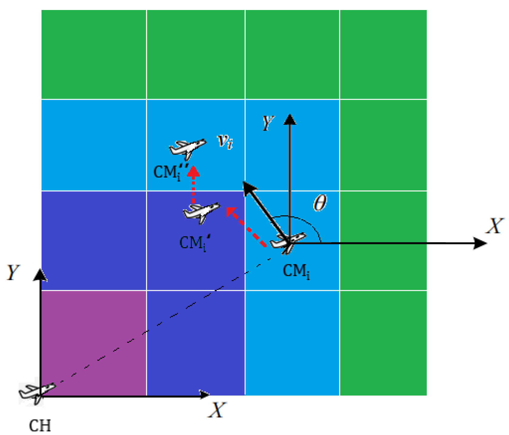
Figure 5 shows the movement trajectory of the CM
during a HELLO message switching period. At time
, the CM
is in the light blue grid; after
l time slots, the CM
moves to the dark blue grid. Then, the CM
moves to the light blue grid again until the next HELLO message exchange starts, i.e., the
moment. As shown in
Table 3, the cluster head can predict the grid position of CM
at any time within the HELLO message exchange cycle according to the prediction model, so as to adjust its own transmitting power in time.
The pseudocode of dynamic transmission power of cluster heads algorithm is listed in Algorithm 3.
| Algorithm 3 Dynamic Transmission Power of Cluster Heads Algorithm |
- Input:
Sender node: CH, receiver node: CM, data message - Output:
- 1:
CH gets the velocity, direction angle and the position information of CM by HELLO message - 2:
CH calculates the position of CM at time t by Equations ( 22) and ( 23) - 3:
After a simple calculation, CH gets the grid which CM is in at time t - 4:
- 5:
return CH will send the data message to CM with the power of P at time t
|
4.7. Cluster Maintenance
In the FANETs, due to the high-speed movement of UAVs, UAVs often join or leave the cluster. Violent node movement sometimes leads to the updating of the CH and the reconfiguration of network structure, which introduces large computation and communication overhead. Therefore, a reasonable cluster maintenance mechanism is needed to minimize the overhead and maintain the stability of the cluster structure.
4.7.1. Node Exiting Operation
To maintain the clusters effectively, the CHs broadcast their HELLO messages to their CMs periodically with a period T, and a CM replies with an ACK (acknowledgement) message to its CH, immediately after receiving the HELLO message. If the CH cannot receive an ACK from the CM for q periods, the CM is considered to not be in the transmission range and is depleted from the CM list. If a CH leaves the cluster, a CH reselection process is triggered.
4.7.2. Node Joining Operation
When a node exits the old cluster, it sends its HELLO message to the nearest CH to join a new cluster network. The CH will reply with an ACK message to the new node. Then, the new node will update its CH information, and the CH will add the new node to its members list.
The pseudocode of cluster maintenance is listed in Algorithm 4.
| Algorithm 4 Cluster Maintenance |
- 1:
if ACK from CM is not received by CH - 2:
CH will deplete CM from its members list - 3:
The node which just exited the cluster will set its CH to null and broadcast its HELLO message - 4:
The nearest CH’ will reply with an ACK message to the node immediately - 5:
This node will update its CH information to CH’ - 6:
CH’ will add this node to its members list - 7:
end if
|


