Article

IRS-Based UAV-Assisted Low-Altitude Passive Relaying: SER Performance Analysis of Optimal Deployment

1
School of Computer and Information, Hohai University, Nanjing 210098, China
2
State Grid Information & Telecommunication Branch, State Grid Corporation of China, Beijing 100761, China
*
Author to whom correspondence should be addressed.
Electronics 2022, 11(20), 3306; https://doi.org/10.3390/electronics11203306
Submission received: 13 September 2022 / Revised: 5 October 2022 / Accepted: 10 October 2022 / Published: 14 October 2022
(This article belongs to the Special Issue Hybrid Satellite-UAV-Terrestrial Networks for 6G Ubiquitous Coverage)

Abstract

:
This paper presents a method for analyzing the symbol error rate (SER) of a UAV cellular data network based on an IRS. This method can change the distances between the BS, IRS, UAV, and the elevation of the UAV to observe their impacts on the SER; then, a two-dimensional curve diagram of the parameters and the SER is drawn to determine the deployment position of the UAV. Finally, by flexibly changing the maximum angle of the UAV’s transmitted signal and the height of the UAV, the coverage area of the UAV’s cellular data network can be obtained through three-dimensional imaging, function fitting, and the extreme value of the condition function. As a relay of a cellular data network, a UAV can be flexibly deployed at any effective position at a low altitude to compensate for the limited coverage of the base station and the poor quality of the user’s received signal. In particular, an IRS deployed on the surface of a building can generate an equivalent line-of-sight channel to reflect the signal from the base station to the UAV. Using an IRS to change the signal phase and amplitude with the flexible deployment of UAVs can give priority to solving the problems of cellular data network coverage and signal quality in urban scenarios.

1. Introduction

1.1. Research Background

UAV-aided cellular data network communication based on an IRS is not only an effective method for expanding the signal transmission range, but also an important way to improve the signal quality [1,2]. This is important for users in marginal areas, who may experience severe path loss because they are far from the base station or at a poor receiving antenna angle. An IRS can flexibly adjust the amplitude and phase of the received signal and change the propagation direction of the reflected signal [3], while a UAV can achieve more flexible movement and deployment at low altitude [4]. Based on the above characteristics, researchers have shown great interest in the performance analysis of low-altitude wireless relay communication systems in recent years.
As low-altitude relays, UAVs are widely used in wireless communication systems [5,6]. In mobile edge computing systems, UAVs can be deployed at the edge nodes to forward the tasks received from a user to a cloud center or base station for processing, which not only shortens the operating time, but also allows the maximal secure capacity of mobile edge computing systems to be realized [7]. In air-to-ground communication systems, by jointly optimizing scheduling and power allocation and determining the trajectory of a UAV over a certain period of time, the energy consumption required for secure communication is minimized. Thus, the system’s secrecy energy efficiency is significantly improved [8]. In multi-UAV communication systems, according to the advantages of UAVs—low cost, high mobility, and on-demand deployment—the minimum signal-to-noise ratio of the UAVs is maximized through joint optimization of channel allocation and power allocation in order to realize the optimization of the performance of multi-UAV systems [9]. UAVs have been widely used in cellular data networks in recent years because of their characteristics of high mobility and on-demand deployment. The authors of [10] studied the deployment of a UAV as an air base station in fifth-generation communications systems, which solved the deployment problems of UAVs in a three-dimensional space and maximized the system throughput.
An IRS is essentially a metamaterial that integrates a very low-cost and subwavelength structure. It consists of independent and controllable passive electromagnetic reflective elements on a plane, and it operates through software or hardware [11]. The main function of an IRS is to control the reflection phase and amplitude of an incident signal through software programming according to the communication link information fed back by signal transmission, which is essentially an adjustment of the capacitance, resistance, and inductance [12]. IRSs are also widely used in wireless communication systems as assisted passive wireless relays. An IRS can assist orthogonal frequency division multiplexing systems in channel estimation by considering the relationships between the amplitude, phase shift, and frequency of an actual IRS response [13]. In 5G communication networks, signals can be transmitted to a blocking user by utilizing the reflection characteristics of an IRS, thus greatly reducing the probability of interruption of the system [14]. An IRS can also be deployed in communication systems in which listeners are present, which illustrates the effects of the size of the IRS and the optimization of its phase element on the expansion of the security rate of the energy collection area [15]. In terms of power optimization, considering the minimal signal-to-interference-plus-noise ratio (SINR) per user, the power minimization problem of an IRS-assisted downlink non-orthogonal multiple-access system has been proposed. Numerical results have shown that, compared with other schemes, the proposed joint optimization algorithm based on an IRS can significantly reduce the required transmission power. In addition, an IRS and UAV can be jointly deployed in the same wireless communication system to optimize system performance [16,17,18,19]. Therefore, the joint deployment of an IRS and UAV as the low-altitude relay of a wireless communication system is conducive to the optimization of the performance of the system.

1.2. Related Work

Previously, some scholars proposed the use of a UAV as an aerial base station of a cellular data network [20]. A UAV base station can move freely in a network without considering the cell boundary. UAVs can be equipped with base station hardware, regardless of building boundaries, and they can be deployed in appropriate locations to provide cellular data networks for ground users. Therefore, we proposed a physical model in [21]—a low altitude UAV carries an IRS as a passive relay, providing a cascaded LoS channel that can be deployed in traditional mobile communication, and this can cover signal-blind areas well or provide additional channel gain for users with bad channel performance at the cell edge. However, when UAVs act as aerial base stations, the hardware payload limits their flight flexibility, and when they are deployed as signal generators at low altitudes, they produce extremely unstable signals. Therefore, the authors of [22] proposed an IRS-assisted UAV cellular data network communication model that used the flexible deployment of UAVs to solve the problem of small base station signal coverage. This paper determines the optimal distances between the BS, IRS, and UAV by simulating the relationships between the parameters and the received signal’s SER at the UAV. Finally, by drawing three-dimensional images, performing function fitting, and calculating the extreme value of the condition function, the problem of the optimal deployment location of a UAV is solved and the signal coverage area is obtained.

1.3. Improvement and Structure

In this paper, by using an IRS-assisted UAV as the air cellular data network base station, a system model is constructed; based on this, the system performance is analyzed and optimized. Firstly, two cascaded downlinks of the system are constructed: BS–UAV as a line-of-sight (LoS) link and BS–IRS–UAV as a non-line-of-sight (NLoS) link [23]. Then, the SNR formula of the system is derived by assuming a noise type using simulated data. Finally, according to the coding principle of the communication systems, the SER of the system is further deduced [24]. We use the distance between the base station and the IRS, the height of the UAV, the distance between the UAV and the IRS, the number of components, and other parameters to analyze the relationships between them and the SER, and we use a numerical diagram to analyze and discuss the key values of some parameters. In the latter part of the paper, we build a spatial model of UAV deployment at a low altitude. We synthesize all of the parameters as the influence factors of the system SER and deduce a formula for the spatial geometry for a numerical analysis in order to generate the best position for UAV deployment at a low altitude so as to achieve the improvement and optimization of the whole communication system’s performance.
Unlike in the previous system models, this paper reestablishes a cellular data network transmission model in a building area by taking advantage of the advantages of flexible deployment of UAVs and portable items, as well as the characteristics of an IRS that can be used to adjust the amplitude and phase of signals.This model not only avoids the signal-blocking problem caused by occlusion due to buildings, but also solves the problem of the small coverage of the down-tilt signal of the base station.

2. System Model

In this section, we will introduce the model of a UAV-assisted cellular network communication system based on an IRS and the model of the UAV’s optimal deployment position.
The right half of 
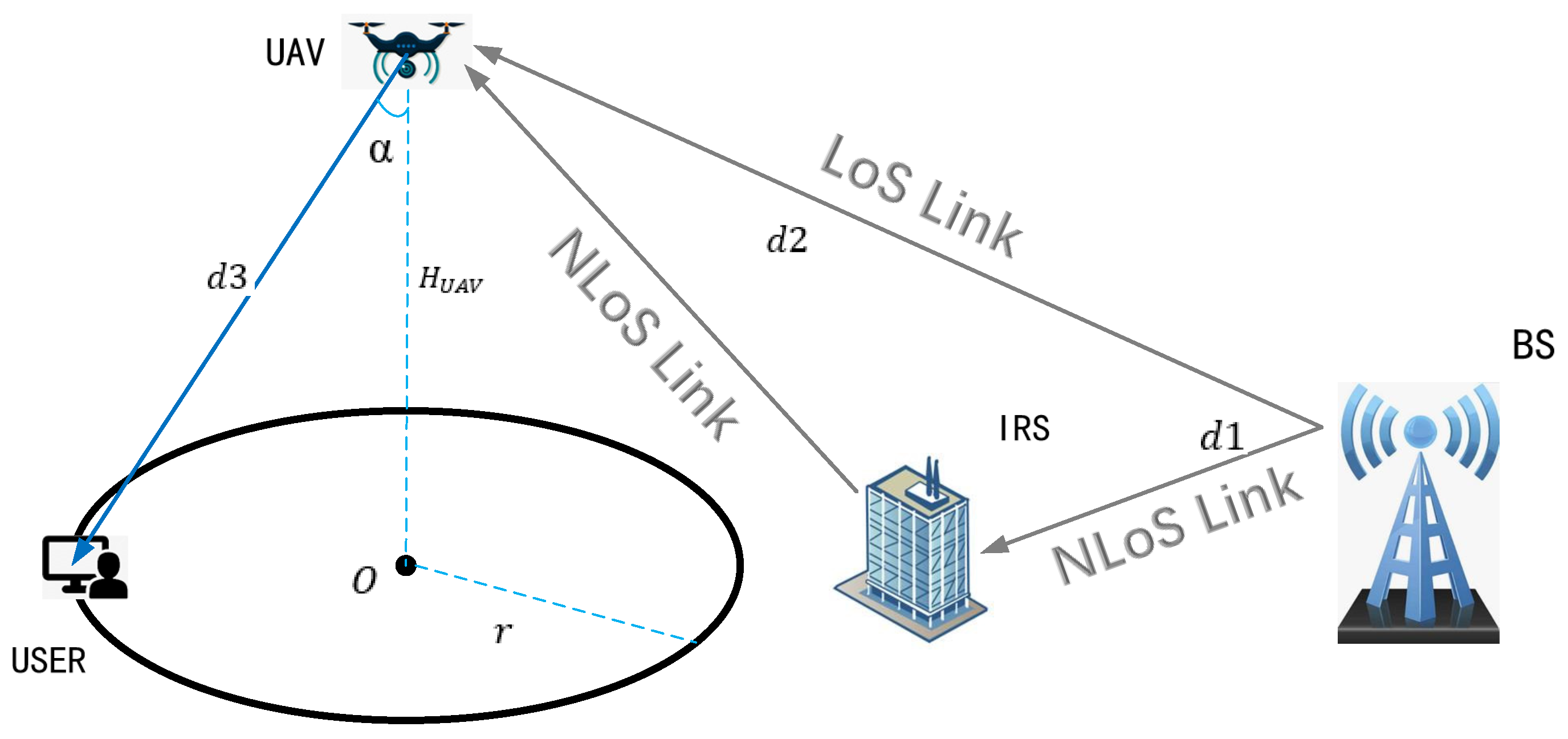
Figure 1 shows the model of the BS–IRS–UAV system. The whole system is divided into two links for signal transmission: the LoS link, in which the signal is transmitted from the base station to the UAV side, and the NLoS link, in which the IRS is used to promote the signal transmission of the link. The downdip antenna of the base station sends most of the signals to the angle at which the IRS is located. After receiving the signals from the downdip antenna, the IRS composed of K = M × N reflecting elements dynamically programs and reconfigures the signals, which are reflected to the position of the UAV [25]. The UAV receives the signals directly from the line-of-sight path and the non-line-of-sight path reflected by the IRS elements. By using the IRS to align the phase of individually reflected signals with that of the line-of-sight path, these signals are constructively combined on the UAV to improve the received signal power.
Assume that the signal sent by the base station is expressed as:
y t = 1 M 1 N A m , n e j θ m , n ,
where A ( m , n ) is the amplitude of the mth row and nth column signal sent from the base station to the IRS, and e j θ m , n is the phase of the mth row and nth column signal sent from the base station to the IRS. Due to the base station itself and the influence of the channel environment, the amplitudes and phases of the signal received by each element on the reflecting surface are different, so the overall signal expression is actually composed of multiple signals with different amplitudes and phases. In order to facilitate the reception of signals, the IRS adjusts the amplitude and phase of the received signals. The signal’s expression after being reflected by the IRS is:
y r = 1 M 1 N A m , n E m , n e j θ m , n e j φ m , n ,
where E m , n is the amplitude adjustment factor of the IRS element at the mth row and nth column, and e j φ m , n is the phase adjustment factor of the IRS element at the mth row and nth column. The choice of IRS is based on the actual needs of the application and the received signal for adaptive adjustment and change. The IRS will flexibly adjust the received signal according to the actual needs.
According to the above analysis, the expression of the signal received by the UAV should be [26]:
y = h 0 X + i = 1 K h k X + n 0 .
where h 0 X is the signal received at the LoS link, and h k X is the signal reflected by the Kth IRS element. The k elements of the IRS are superimposed to form the received signal of the NLoS link, and n 0 is the additive white Gaussian noise at the UAV receiver, with a mean value of 0 and a variance of σ 2 . Next, we deduce the channel coefficients h 0 and h k of the two links through the relationship between the transmitted power and lost power.
Since cellular network data base stations are already equipped with down-sloping antennas to serve terrestrial users, the power over the NLoS link is much higher than that over the LoS link. By querying a 3GPP website [27], the following expression of the signal power of the base station downdip angle can be obtained:
A ( θ ) = min 12 θ θ etilt θ 3 d B 2 , S L A ,
where θ is the angle between the line between the BS and IRS or the line between the BS, UAV, and the horizontal line (which is negative if it is higher than the horizontal line); θ etilt is the dip angle of the base station antenna, which can be found by querying 3GPP and is set to 15 . θ 3 d B is equal to 10 and S L A = 20 dB. The power transmitted to the LoS and NLoS links can be obtained with the following formula:
P T ( θ ) = P T + A θ ,
where P T is the original transmitting power of the base station, whose value is set as 46 dBm.
When signals are transmitted in the LoS link and NLoS link, corresponding power losses are generated. Considering the different link attributes, the power losses of the two links are also calculated differently. In 3GPP, the path loss formula of the LoS link is:
P L L o S = 28 + 22 log 10 ( d ) + 20 log 10 ( f ) ,
where d is the distance between the signal transmitting point at the base station and the UAV, and f is the carrier frequency.
The power loss of the NLoS link also changes with the increase in the path, and the path loss expression is different before and after 22.5 m. The expression of the function between the distance and power of the NLoS link is as follows:
P L N L o S ( x ) = max P L L o S , P L 0 ( x ) , H U A V < 22.5 m P L 1 ( x ) , H U A V > 22.5 m .
In the above formula, the expressions of P L 0 ( x ) and P L 1 ( x ) are as follows:
P L 0 ( x ) = 13.54 + 39.08 log 10 ( x ) + 20 log 10 ( f ) 0.6 H U A V 1.5 ,
P L 1 ( x ) = 17.5 + 46 7 log 10 H U A V log 10 ( x ) + 20 log 10 40 π f 3 .
Given the above path loss power expression for the NLoS link, we divide the NLoS link into two paths: the path from the BS to element K and the path from element K to the UAV.
Assuming that the distance between the base station and a component of the IRS is d 1 ( k ) , then the power loss from the base station to element K is:
P L B S k = P L N L o S d 1 ( k ) .
Assuming that the distance from element K to the UAV is d 2 ( k ) , then the power loss from element K to the UAV is:
P L k U A V = P L N L o S d 1 ( k ) + d 2 ( k ) P L N L o S d 1 ( k )
After the transmission power and path loss are obtained, the receiving power P R ( L o S ) and P R ( k ) of the LoS link and NLoS link is:
P R ( L o S ) = P T θ 0 P L L o S ,
P R ( k ) = P T θ k P L B S k P L I R S P L k U A V .
In the above formula, θ 0 and θ k are the angle between the UAV and the base station and the angle between the IRS element K and the base station, respectively. The received power of the two links can be obtained, and h 0 and h k are:
h ( 0 ) = P R ( L o S ) e j φ 0 ,
h ( k ) = P k ( k ) e j φ k .
In order to obtain the optimal signal, we set the phases φ 0 and φ k to 0, and then obtain the signal expression of the UAV receiver:
y U A V = h 0 + i = 1 K h ( k ) .
Therefore, combined with additive white Gaussian noise, the SNR at the UAV is expressed as:
r = y U A V 2 E s N 0 ,
where N 0 is the power of the additive white Gaussian noise, and E s is the average transmitted energy of each symbol.
According to communication coding theory, the SER can represent the quality of a signal, and it can be expressed as:
P e , B P S K = 1 2 ( 1 erf ( r ) ) = 1 2 erf c ( r ) .
The error function (ERF) is expressed as:
erf ( x ) = 2 π 0 x e y 2 d y .
The right-tail function of the standard normal distribution—the Q function, which is also known as the complementary accumulative distribution of the standard normal distribution. It is commonly used to represent the bit error rate of transmitted signals. The relationship between the Q function and the error function (ERF) is:
Q ( α ) = 1 2 erf c α 2 .
Therefore, the Q function can be used to express the bit error rate at the UAV receiver:
P e , B P S K = 1 2 erfc c ( r ) = Q ( 2 r ) .
After analyzing the SER at the UAV, a system model of IRS–UAV–USER needs to be built in order to ensure a better signal at the USER terminal. As shown in Figure 1, after the IRS receives the signal from the base station, it adjusts the signal phase amplitude and transmits the signal to the UAV terminal. The UAV, which acts as a base station for the cellular data network, sends the signals that it receives to the user, covering a roughly pyramidal area.
Due to signal attenuation, the distance between the UAV end and the USER end is limited. Therefore, Figure 1 shows the area that can be covered by the UAV when all users can receive signals normally. We stipulate that the farthest distance of the signal received by the user is d3 (beyond d3, the signal received by the USER cannot be decoded correctly). The distance between the UAV and the point O directly below the ground is the height of the UAV. The circle with O as the center and r as the radius is the signal-receiving area. Users in the signal-receiving area can receive signals from the UAV normally. The angle included between the vertical line H U A V and d3 is α .
In this model, the signal loss from the UAV to the USER and the bit error rate at the USER end are calculated in the same way as those in the BS–IRS–UAV system model, and the specific formula is as follows:
P L U A V U S E R = P L N L o S ( d 3 ) ,
y U S E R = y U A V P L U A V U S E R ,
where P L U A V U S E R is the path loss between the UAV and the USER, and y U S E R is the expression of the signal received by the USER.

3. Numerical Results

Through the calculation of the above formula, it can be concluded that the SER at the receiving end of the UAV model of the BS–IRS–UAV system is affected by many parameters, including the number of reflectors K, the distance d1 between the BS and the IRS, the distance d2 between the IRS and the UAV, and the distance d between the BS and the UAV. However, when the UAV reaches a certain height, the angle between the UAV and the BS is too large, which makes the signal that is directly transmitted from the base station to the UAV in the LoS link very weak. When digitally superimposed with the path attenuation power, the received power at the receiving end of the UAV is basically 0 (whether it is completely 0 depends on the flight altitude of the UAV). The received power of the LoS link is much smaller than that of the NLoS link. Therefore, in this section, all numerical results will be analyzed in order to demonstrate the system performance in terms of parameters other than the distance between the BS and UAV.
Table 1 gives the values of some constant parameters that will be used in the simulation test in the form of constant values in the simulation analysis.
Next, we analyze the influence of other variables on the receiving power of the UAV end. 
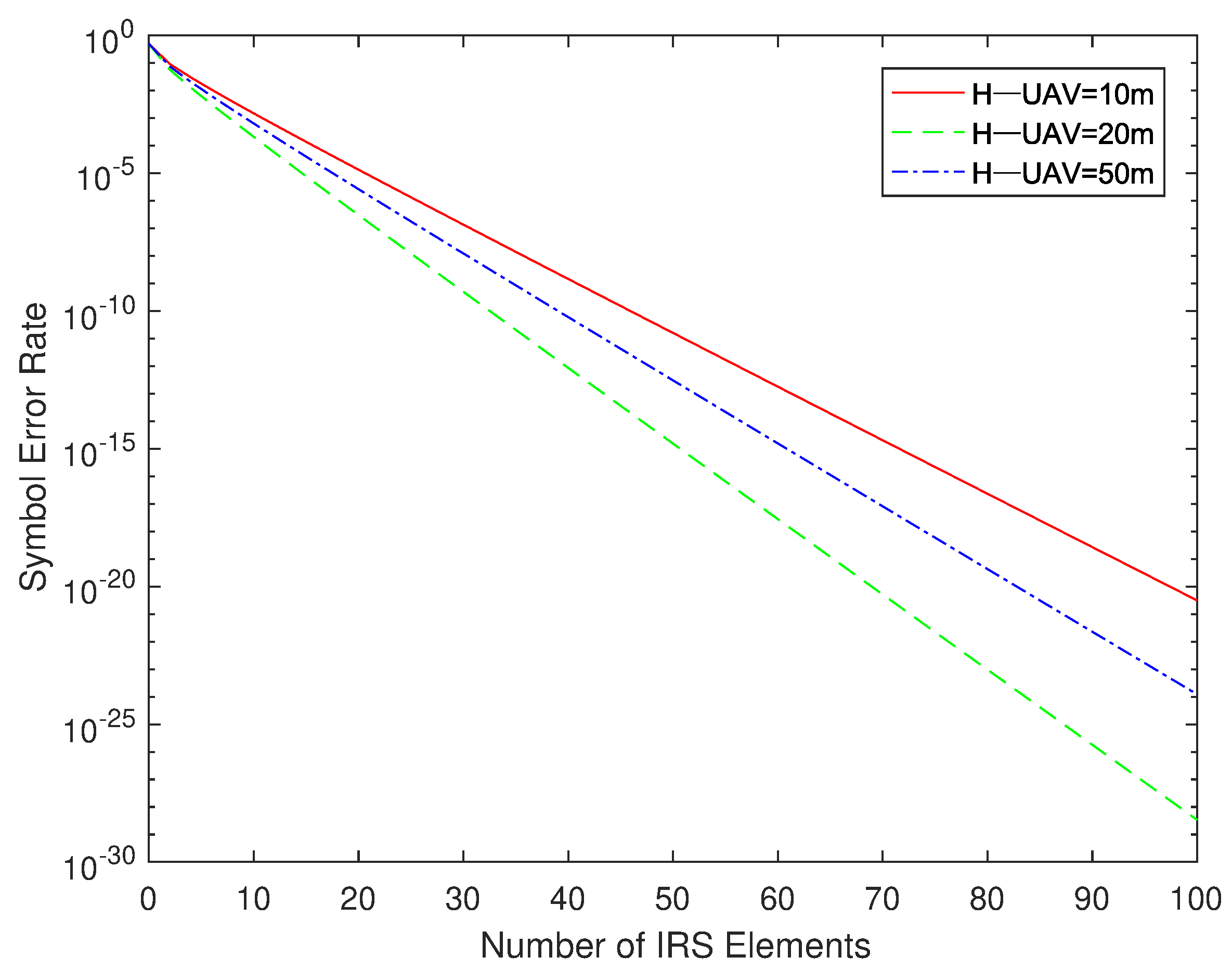
Figure 2 shows the influence of the number of reflective elements of the IRS on the SER of the signal received at the UAV end. The height of the UAV was set to 10, 20, and 50 m, respectively, and the relationships between the SER of the UAV’s received signal and the number of reflectors K were compared at different heights.
It can be seen in Figure 2 that the height of the UAV does not affect the linear relationship between the received signal’s SER at the receiving end and the number of elements K. Selecting a height near the critical value as a reference, it is found that the SER of the received signal of the UAV at the height of 20 m is significantly better than those at the height of 10 and 50 m. When the number of reflective elements K of the IRS gradually increases, the SER of the UAV’s received signals at different altitudes shows a downward trend. It can be seen that, when the number of reflective elements K is set to 50, the SER at the receiving end has reached an ideal level.
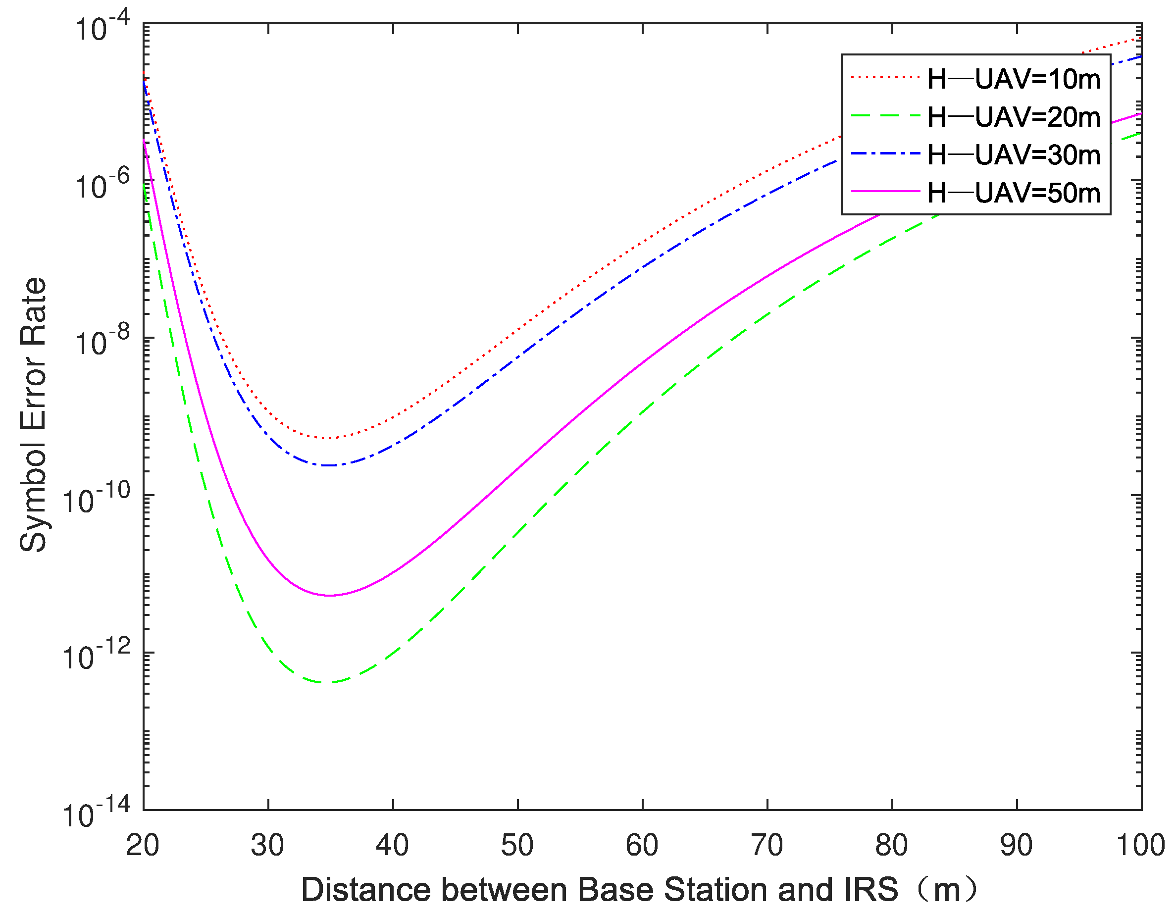
We fixed the number of IRS elements at 50, and then tested the linear relationship between the distance d1 (for the convenience of simulation, the values of the distances between all components of the IRS and the base station were equal by default, and are uniformly represented by d1 and d2) between the base station and the IRS and the SER. At the same time, we continued to add the UAV height as the third variable in the system simulation test.
Figure 3 shows the linear relationship between d1 and the system SER at different UAV heights, and it shows the UAV heights under four conditions: 10, 20, 30, and 50 m. Four different heights were selected between the heights close to the critical point and those far from the critical point to verify the optimal value of H U A V . As we can see in the figure, whether H U A V is larger than 22.5 m or not does not affect the linear relationship between d1 and the SER (first decreasing and then increasing). With the same d1, the UAV with a height of 10 m receives the highest SER, and the UAV with a height of 20 m receives the lowest SER. The SERs of the signals received by UAVs at altitudes of 30 and 50 m are between 10 and 20 m, and the former is significantly higher than the latter. Although the performance of the UAV at 20 m is obviously better than that at other heights, considering the actual situation—a 20-m-high UAV cannot achieve a wider coverage range—we should make the best choice in the selection of the UAV height based on the combined benefits of the SER and coverage.
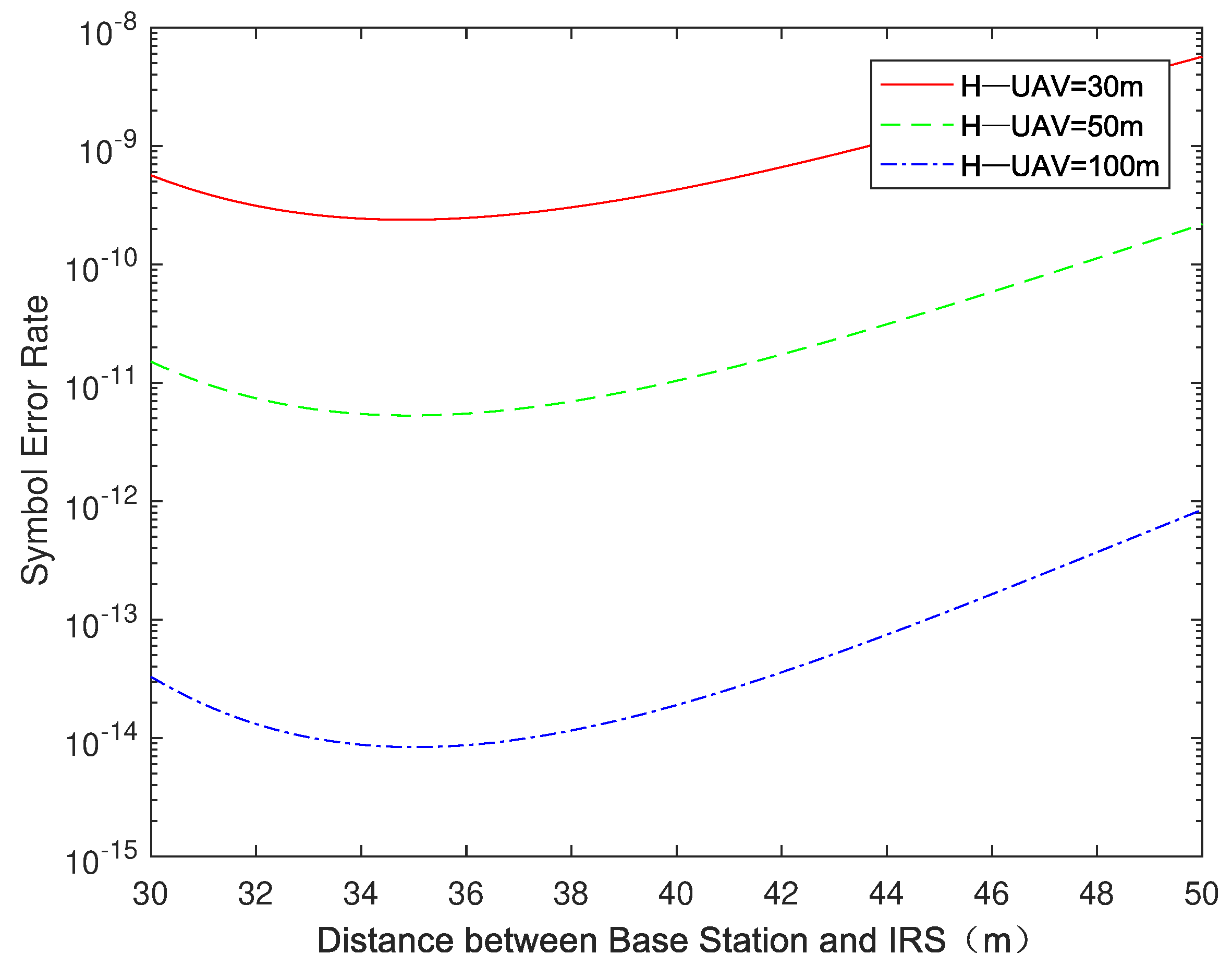
In Figure 4, we reset d2 from 50 to 100 m to increase the maximum altitude that the UAV can reach. At the same time, we narrowed the range of d1 to 30–50 m and reset the values of H U A V to 30, 50, and 100 m, respectively. One can see that, when d2 is constant, the larger the height of UAV is, the lower the SER of the system will be. This conclusion applies to the communication system model in the low-altitude range higher than 22.5 m. After determining the accurate range of d1 and conducting a comparison of specific values in the MATLAB simulation, it can be determined that when d1 = 35 m, the system’s SER reaches the lowest value.
After the determination of the optimal distance of d1, the following simulation analysis will be conducted for the value of d2. All of the above simulations involved fixing d2 at a specific value at which H U A V could be flexibly changed (provided that d2 was greater than or equal to H U A V ). The simulation results show that the SER of the system always decreases with the increase in H U A V after the upper limit of d2 is set. Therefore, we will keep the value of d2 equal to that of H U A V —that is, the UAV is active directly over the IRS—to simulate the relationship between d2 and the SER.
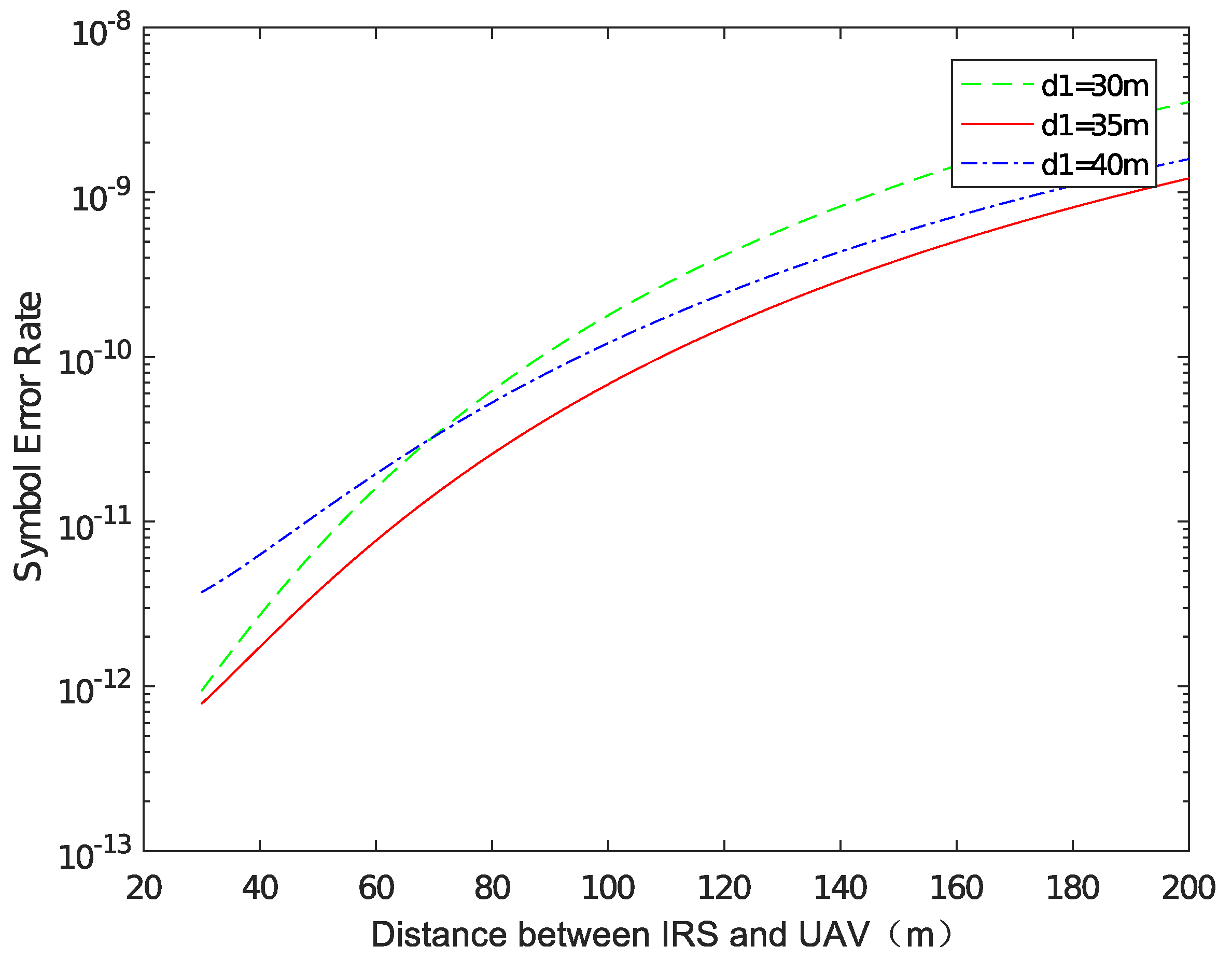
As shown in Figure 5, at different values of d1, the SER of the signals received by the UAV gradually increases as d2 increases from 30 to 200 m. This is because an increase in d2 does not affect the size of the signal received from the base station for some factors, but as d2 increases, the path loss on the NLoS link increases, as does the SER of the signal received by the UAV. Therefore, in order to keep the SER of the signal obtained from the UAV as low as possible, it is necessary to ensure that d2 is reduced as much as possible while other values are equal.
It can be seen from the above simulation that, with the same d2, when the value of H U A V is equal to that of d2, the SER of the signal received by the UAV is the lowest, and the simulation test of IRS–UAV–USER is continued under this condition.
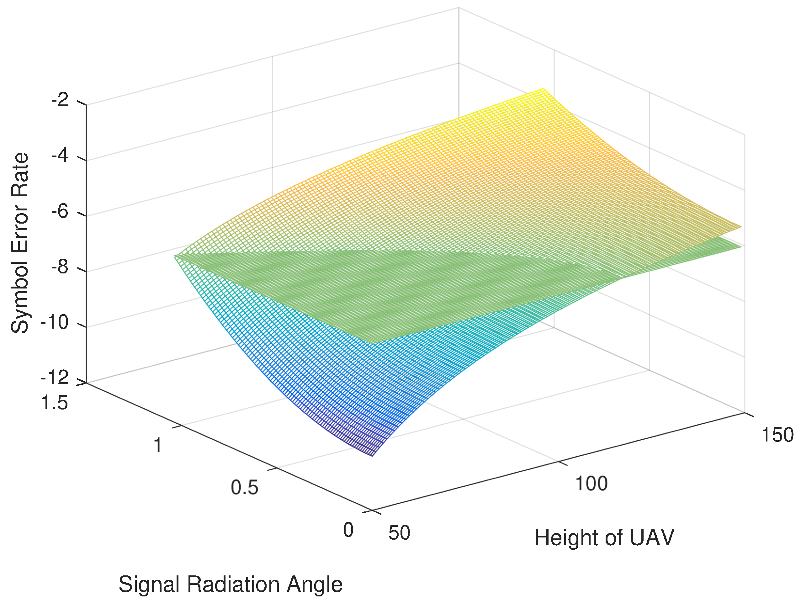
Given that H U A V is equal to d2 (the UAV moves directly above the IRS), the value of H U A V and the value of the included angle α can be flexibly changed. By observing the SER of the signal received by the USER, the optimal deployment position of the UAV can be determined. Now, the height of the UAV and angle α are taken as two independent variables affecting the USER’s SER. The SER expression for the USER is calculated by using Formulas (7)–(9) and (18)–(21). With the SER as the dependent variable, the joint three-dimensional image of the influence of H U A V and α on the USER’s SER is drawn.
As shown in Figure 6, the surface is a three-dimensional image of H U A V , α , and the USER’s SER, the plane is the maximum SER acceptable to the USER for cellular data, and the value is set to 10 6 . The intersection of the plane and the surface is the boundary of where the user can receive a good signal. It can be seen in the figure that the SER of the signal received by the USER shows a monotonically increasing trend with either variable of H U A V or α , that is, if one variable of H U A V or α is fixed and the value of the other variable is changed, the SER always increases with the increase in this variable.
The coordinate points set at the intersection line represent the critical point for ensuring that the USER can receive good signals. In theory, all of the coordinate points of the UAV on the intersection line can achieve a good cellular data transmission effect. However, in order to achieve the maximum signal coverage area, we extracted coordinate points on the intersection line and performed function fitting in two-dimensional coordinates. The binomial expression obtained by fitting is:
α = p 1 · H U A V 2 + p 2 · H U A V + p 3 ,
where p 1 = 0.0001417 , p 2 = 0.01029 , and p 3 = 0.8557 . In order to obtain a better signal transmission effect, it is necessary to improve the coverage area as much as possible on the premise of ensuring normal signal reception. It is known that the intersection of the plane, surface, and X-axis is 117, that is, the range of values of H U A V is 0–117 m.
After specifying the height of the UAV and the range of variation in the radiation angle, we need to explore the relationship between the above two variables and the coverage area S because the coverage area S is directly related to the radius R of the circle at the bottom of the cone, and R can be expressed as:
R = tan α · H U A V .
Therefore, the expression of the coverage area S is:
S = π · tan 2 α · H U A V 2 .
Therefore, the problem of finding the optimal deployment position of the UAV is transformed into the problem of finding the extreme value of Formula (26) under the condition of Formula (24). This is obtained by using the Lagrange multiplier method; when H U A V = 63 m, S achieves its maximum value, which is about 23,500 m 2 .

4. Conclusions

This paper has illustrated a UAV-assisted cellular data network model based on an IRS and introduced the SER as the evaluation standard for signal quality. At the same time, we extended the original model to build a model for the optimal deployment position of the UAV. Through the derivation of the formula, we obtained the expression of the SER of the signal received at the UAV end and conducted a simulation analysis by changing various parameters in the original model. After determining the optimal value of each parameter, we also obtained the lowest SER of the signal received at the UAV end when the UAV is directly above the IRS. After that, the expression of the received signal and path loss formula at the UAV were used to derive the expression of the SER of signal received at the USER end in the model of the optimal UAV deployment position. Meanwhile, a simulation test of the optimal UAV deployment position was carried out. Finally, the optimal UAV deployment position was obtained through graphic simulation, determination of the intersection point, function fitting, and an extreme value operation. This not only ensures that the coverage users can get good signals, but also achieves the goal of maximizing coverage.
In real life, it is a feasible choice to use an IRS deployed in a building cluster and a UAV deployed at a low altitude as the transmission medium of a cellular data network. In terms of cost, this model will not cause excessive cost consumption when applied to real life. In terms of energy efficiency, the simulation results show that the model can achieve better signal transmission. In terms of feasibility, the deployment of an IRS in a building complex and the deployment of a UAV at a low altitude meet the needs of real life. If the practice proves that this model is suitable for real life, deploying a network in a city with numerous and dense buildings will have a very significant effect.
Future research can also be carried out on the probability of interruption of signal transmission and the received power of the signal terminal in order to optimize and improve the relevant model. As an efficient communication system model, UAV-assisted cellular data relay communication based on an IRS is expected to provide users with more efficient and convenient services.

Author Contributions

Conceptualization of this study, Methodology, Software, Writing—Original draft preparation, T.L.; Funding acquisition, Writing—review, Data curation, M.M.; Investigation, M.X.; Formal Analysis, Y.H.; Resources, Y.F.; Supervision, R.S. All authors have read and agreed to the published version of the manuscript.

Funding

This research was funded by the National Natural Science Foundation of China, grant number 62271190.

Institutional Review Board Statement

Not applicable.

Informed Consent Statement

Not applicable.

Data Availability Statement

Not applicable.

Conflicts of Interest

The authors declare that they have no conflict of interest.

Abbreviations

The following abbreviations are used in this manuscript:
UAVUnmanned Aerial Vehicle
BSBase Station
IRSIntelligent Reflecting Surface
SERSymbol Error Rate

References

  1. Song, X.; Zhao, Y.; Wu, Z.; Yang, Z.; Tang, J. Joint Trajectory and Communication Design for IRS-Assisted UAV Networks. IEEE Wirel. Commun. Lett. 2022, 11, 1538–1542. [Google Scholar] [CrossRef]
  2. Fang, S.; Chen, G.; Li, Y. Joint Optimization for Secure Intelligent Reflecting Surface Assisted UAV Networks. IEEE Wirel. Commun. Lett. 2021, 10, 276–280. [Google Scholar] [CrossRef]
  3. Wu, Q.; Zhang, S.; Zheng, B.; You, C.; Zhang, R. Intelligent Reflecting Surface-Aided Wireless Communications: A Tutorial. IEEE Trans. Commun. 2021, 69, 3313–3351. [Google Scholar] [CrossRef]
  4. Shafique, T.; Tabassum, H.; Hossain, E. Optimization of Wireless Relaying with Flexible UAV-Borne Reflecting Surfaces. IEEE Trans. Commun. 2021, 69, 309–325. [Google Scholar] [CrossRef]
  5. Wang, Y.; Feng, W.; Wang, J.; Quek, T.Q.S. Hybrid Satellite-UAV-Terrestrial Networks for 6G Ubiquitous Coverage: A Maritime Communications Perspective. IEEE J. Sel. Areas Commun. 2021, 39, 3475–3490. [Google Scholar] [CrossRef]
  6. Liu, C.; Feng, W.; Chen, Y.; Wang, C.-X.; Ge, N. Cell-Free Satellite-UAV Networks for 6G Wide-Area Internet of Things. IEEE J. Sel. Areas Commun. 2021, 39, 1116–1131. [Google Scholar] [CrossRef]
  7. Han, D.; Shi, T. Secrecy capacity maximization for a UAV-assisted MEC system. China Commun. 2020, 17, 64–81. [Google Scholar] [CrossRef]
  8. Tao, Q.; Su, G.; Chen, B.; Dai, M.; Lin, X.; Wang, H. Secrecy Energy Efficiency Maximization for UAV Enabled Communication Systems. In Proceedings of the 2021 30th Wireless and Optical Communications Conference (WOCC), Taipei, Taiwan, 7–8 October 2021; pp. 240–244. [Google Scholar]
  9. Zhou, L.; Dong, Y.; Hong, M.; Shi, Q. Joint Channel Assignment And Power Allocation for Multi-UAVs Communication Systems. In Proceedings of the 2020 IEEE 21st International Workshop on Signal Processing Advances in Wireless Communications (SPAWC), Atlanta, GA, USA, 26–29 May 2020; pp. 1–5. [Google Scholar]
  10. Gupta, N.; Agarwal, S.; Mishra, D. UAV Deployment for Throughput Maximization in a UAV-Assisted Cellular Communications. In Proceedings of the 2021 IEEE 32nd Annual International Symposium on Personal, Indoor and Mobile Radio Communications (PIMRC), Helsinki, Finland, 13–16 September 2021; pp. 1055–1060. [Google Scholar]
  11. Renzo, M.D.; Zappone, A.; Debbah, M.; Alouini, M.-S.; Yuen, C.; de Rosny, J.; Tretyakov, S. Smart Radio Environments Empowered by Reconfigurable Intelligent Surfaces: How It Works, State of Research, and The Road Ahead. IEEE J. Sel. Areas Commun. 2020, 38, 2450–2525. [Google Scholar] [CrossRef]
  12. Long, W.; Chen, R.; Moretti, M.; Zhang, W.; Li, J. A Promising Technology for 6G Wireless Networks: Intelligent Reflecting Surface. J. Commun. Inf. Netw. 2021, 6, 1–16. [Google Scholar] [CrossRef]
  13. Yang, W.; Li, H.; Li, M.; Liu, Y.; Liu, Q. Channel Estimation for Practical IRS-Assisted OFDM Systems. In Proceedings of the 2021 IEEE Wireless Communications and Networking Conference Workshops (WCNCW), Nanjing, China, 29 March 2021; pp. 1–6. [Google Scholar]
  14. Swami, P.; Bhatia, V. Impact of Distance on Outage Probability in IRS-NOMA for Beyond 5G Networks. In Proceedings of the 2021 IEEE 18th Annual Consumer Communications & Networking Conference (CCNC), Las Vegas, NV, USA, 9–12 January 2021; p. 12. [Google Scholar]
  15. Saeidi, M.A.; Emadi, M.J. IRS-based Secrecy Rate Analysis in Presence of an Energy Harvesting Eavesdropper. In Proceedings of the 2020 Iran Workshop on Communication and Information Theory (IWCIT), Tehran, Iran, 26–28 May 2020; pp. 1–5. [Google Scholar]
  16. Wang, W.; Li, Y.; Xu, Q.; Peng, B.; Lu, M.; Lu, Q. Design of IRS-assisted UAV System for Transmission Line Inspection. In Proceedings of the 2021 IEEE 21st International Conference on Communication Technology (ICCT), Tianjin, China, 13–16 October 2021; pp. 675–680. [Google Scholar]
  17. Zhang, X.; Zhang, H.; Du, W.; Long, K.; Nallanathan, A. IRS Empowered UAV Wireless Communication with Resource Allocation, Reflecting Design and Trajectory Optimization. IEEE Trans. Wirel. Commun. 2022, 21, 7867–7880. [Google Scholar] [CrossRef]
  18. Al-Jarrah, M.; Alsusa, E.; Al-Dweik, A.; So, D.K.C. Capacity Analysis of IRS-Based UAV Communications with Imperfect Phase Compensation. IEEE Wirel. Commun. Lett. 2021, 10, 1479–1483. [Google Scholar] [CrossRef]
  19. Wei, Z.; Cai, Y.; Sun, Z.; Ng, D.W.K.; Yuan, J. Sum-Rate Maximization for IRS-Assisted UAV OFDMA Communication Systems. IEEE Trans. Wirel. Commun. 2021, 20, 2530–2550. [Google Scholar] [CrossRef]
  20. Fotouhi, A.; Ding, M.; Hassan, M. Service on Demand: Drone Base Stations Cruising in the Cellular Network. In Proceedings of the 2017 IEEE Globecom Workshops (GC Wkshps), Singapore, 4–8 December 2017; pp. 1–6. [Google Scholar]
  21. Mao, M.; Cao, N.; Li, R.; Shi, R. IRS-assisted low altitude passive aerial relaying. Comput. Commun. 2021, 175, 150–155. [Google Scholar] [CrossRef]
  22. Ma, D.; Ding, M.; Hassan, M. Enhancing Cellular Communications for UAVs via Intelligent Reflective Surface. In Proceedings of the 2020 IEEE Wireless Communications and Networking Conference (WCNC), Seoul, Korea, 25–28 May 2020; pp. 1–6. [Google Scholar]
  23. Arnau, J.; Atzeni, I.; Kountouris, M. Impact of LOS/NLOS propagation and path loss in ultra-dense cellular networks. In Proceedings of the 2016 IEEE International Conference on Communications (ICC), Kuala Lumpur, Malaysia, 22–27 May 2016; pp. 1–6. [Google Scholar]
  24. Timande, B.D.; Nigam, M.K. Channel capacity and bit error rate analysis in wireless communication system over Rayleigh fading channel. Int. J. Wirel. Mob. Comput. 2022, 22, 56–65. [Google Scholar] [CrossRef]
  25. Nath, S.S.; Rabindranath, B. Intelligent reflecting surface assisted MIMO communication system: A review. Phys. Commun. 2021, 47, 101386. [Google Scholar]
  26. Peethala, D.; Kaiser, T.; Vinck, A.J.H. Reliability Analysis of Centralized Radio Access Networks in Non-Line-of-Sight and Line-of-Sight Scenarios. IEEE Access 2019, 7, 18311–18318. [Google Scholar] [CrossRef]
  27. 3GPP TR Series Standard. Available online: https://www.3gpp.org/ (accessed on 30 June 2022).
Figure 1. UAV-based cellular data network using an IRS system.
Electronics 11 03306 g001
Figure 2. Symbol error rate versus the number of IRS elements.
Electronics 11 03306 g002
Figure 3. Symbol error rate versus d 1 ; K = 50.
Electronics 11 03306 g003
Figure 4. Symbol error rate versus d1; 30 m < d1 < 50 m, H U A V > 22.5 m.
Electronics 11 03306 g004
Figure 5. Symbol error rate versus d2.
Electronics 11 03306 g005
Figure 6. Symbol error rate of the USER versus α and H U A V .
Electronics 11 03306 g006
Table 1. Parameter symbols and values.
ParameterSymbolValue
Carrier frequencyf2 GHz
Base station transmitting power P T 46 dBm
Dip angle of the base station θ e t i l t 15
Angle between the base station and IRS θ 0
The angle of 3 dB θ 3 d B 10
Signal phase of the LoS link φ 0 0
Signal phase of the NLoS link φ k 0
Reflection power loss of IRS P L I R S 1 dB
The critical parametersSLA20 dB
Publisher’s Note: MDPI stays neutral with regard to jurisdictional claims in published maps and institutional affiliations.

