1. Introduction
Millimeter-wave (mmWave) technology has attracted frequent research interest for use in the future fifth-generation new radio (5G NR) with its advantage of high-speed communication. The unlicensed Wireless Gigabit Alliance (WiGig) technology received considerable attention from service providers because a contiguous 14 GHz was allocated from 57 to 71 GHz [
1], which supports a gigabit wireless connectivity of a distance of approximately 10 m. The WiGig technology has been commercialized and used for various applications ranging from Internet access points (APs) to set-top boxes for televisions [
2]. For the terminals, investigations on antenna techniques focus on designing wideband MIMO antennas [
3,
4]. In addition, WiGig terminal antennas with high-gain full-coverage radiating beams are of importance for the communication link budget.
From this perspective, it was assumed that both the endfire antenna and the broadside antenna are integrated to achieve a satisfactory coverage. Endfire antenna arrays are located on the edges of the terminals, and enabled by a passive beam-forming or beam-switching technique for endfire scanning. The broadside antenna is utilized to combine the blind angle with the broadside direction. Meanwhile, the effect from the phone shell should be considered, especially for the mmWave antenna with high sensitivity.
Different authors have proposed co-designs of mmWave endfire antennas and phone shells [
5,
6]. In these examples, mmWave mobile phone antenna designs focus on endfire radiation with the etched slot in the metal frame. The endfire antennas proposed in [
5] and [
6] support beam steering angles of at least
and
. Therefore, the limitations of the beam steering angles of the endfire antennas result in a blind angle in the broadside direction. Therefore, the broadside antenna can be added to compensate for the radiation-blind area. In [
7], a mmWave 5G cellular handset antenna is proposed which achieves the foreside beam-forming coverage using antenna-on-display. The proposed antenna can radiate through the phone screen to free space with the broadside pattern. However, it suffers from a low radiation efficiency of 30.1%.
An alternative way to create the broadside antenna is using a superstrate antenna. In recent years, a dielectric superstrate has been achieved through the Fabry–Perot antenna (FPA) and frequency-selective surface (FSS) antenna for high-gain purposes [
8,
9]. However, the design suffers from narrow bandwidth (<15.8%) [
8] for WiGig terminal applications. Bandwidth enhancement has been achieved using multilayer superstrate, but this results in a complex structure. Meanwhile, it is challenging to install a MIMO antenna in the FPA due to cavity resonance effects. Meanwhile, an antenna with a flat lens is suitable for MIMO application [
10], but it requires a specific focal point with a large profile (50.6 mm or 4.72
) that is beyond the scope of terminal thickness. The flat lens is loaded with a periodic printed structure, which affects the electromagnetic compatibility of the device when reducing its focal point. Therefore, the current antenna techniques still face challenges to achieve high isolation, a wide operating band, and a low-profile structure when used for MIMO terminals.
In this paper, we propose a simple dielectric loading technique to enhance the antenna gain over a wide bandwidth for a WiGig terminal device. The operation of the dielectric cover is investigated in depth to take full advantage of the existing phone shells which are dielectric, for use in wireless charging. It avoids the use of the printing periodic structure and is suitable for MIMO applications. Compared with the cavity-based dielectric loading antenna with gain enhancement in [
11,
12], the dielectric loading technique proposed here has almost no impact on the antenna operating bandwidth from 57.0 to 71.0 GHz (21.9%), while providing 2.5 dB gain enhancement on the broadside direction. In addition, the MIMO antenna is designed in a compact configuration with more than 15 dB isolation, which is suitable for being deployed in small terminals with a dielectric cover. The proposed multiple antenna element can also be implemented in the transmitting side with the same methodology.
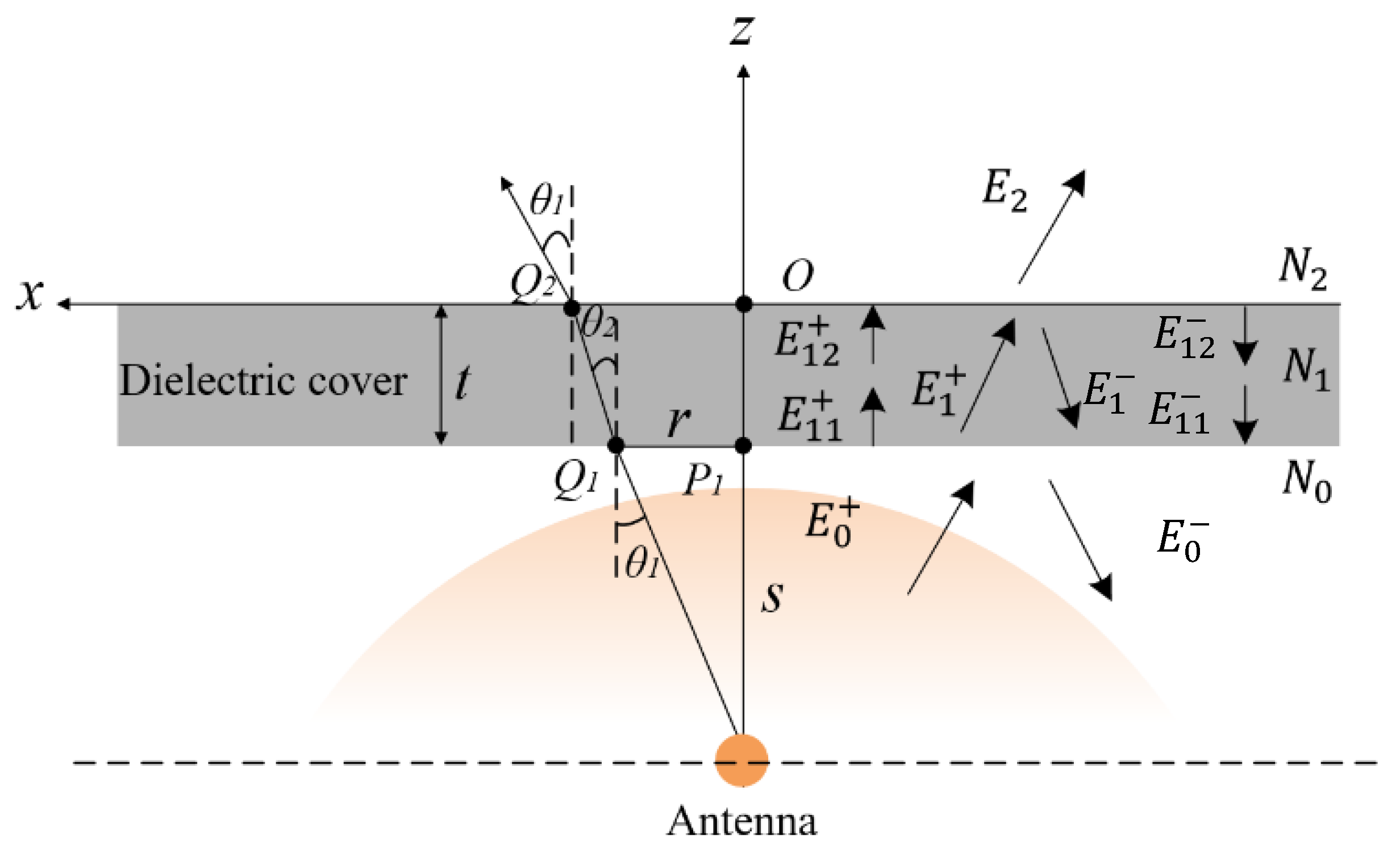
2. Operation of the Dielectric Cover
The impact of the dielectric loading of the antenna is investigated by utilizing ray trajectory and a transmission matrix, aiming to realize a balance between the gain enhancement and impedance matching of the antenna.
The antenna gain enhancement benefits from the change in the phase distribution of the electromagnetic waves by passing through the dielectric cover, as indicated in
Figure 1. Based on the ray trajectory technique, the reflective index of
n of the dielectric cover is
where
and
are the incidence and refraction angles, respectively, and
and
are the relative permeability and relative permittivity, respectively.
The trigonometric functions of refraction angle are as follows:
where
s is the distance from the antenna to the lower surface of dielectric phone case,
r is the distance from the point
to the center of vertical axis,
T is the thickness of the dielectric cover, and
is wavelength of the center frequency in free space.
The phase difference of the electromagnetic radiation from the antenna source to the lower surface of the dielectric cover can be expressed as follows:
The phase difference of the electromagnetic radiation from the lower surface to the upper surface of the dielectric cover can be expressed as follows:
The phase difference of the electromagnetic radiation from the upper surface of the dielectric cover to free space can be expressed as follows:
where
z is the vertical distance from the upper surface of the dielectric cover to the free space. Therefore, the phase difference of the electromagnetic radiation from the antenna source to free space can be expressed as follows:
The equivalent phase surface of
is calculated using
Table 1 shows the original values of the parameters labeled in
Figure 1.
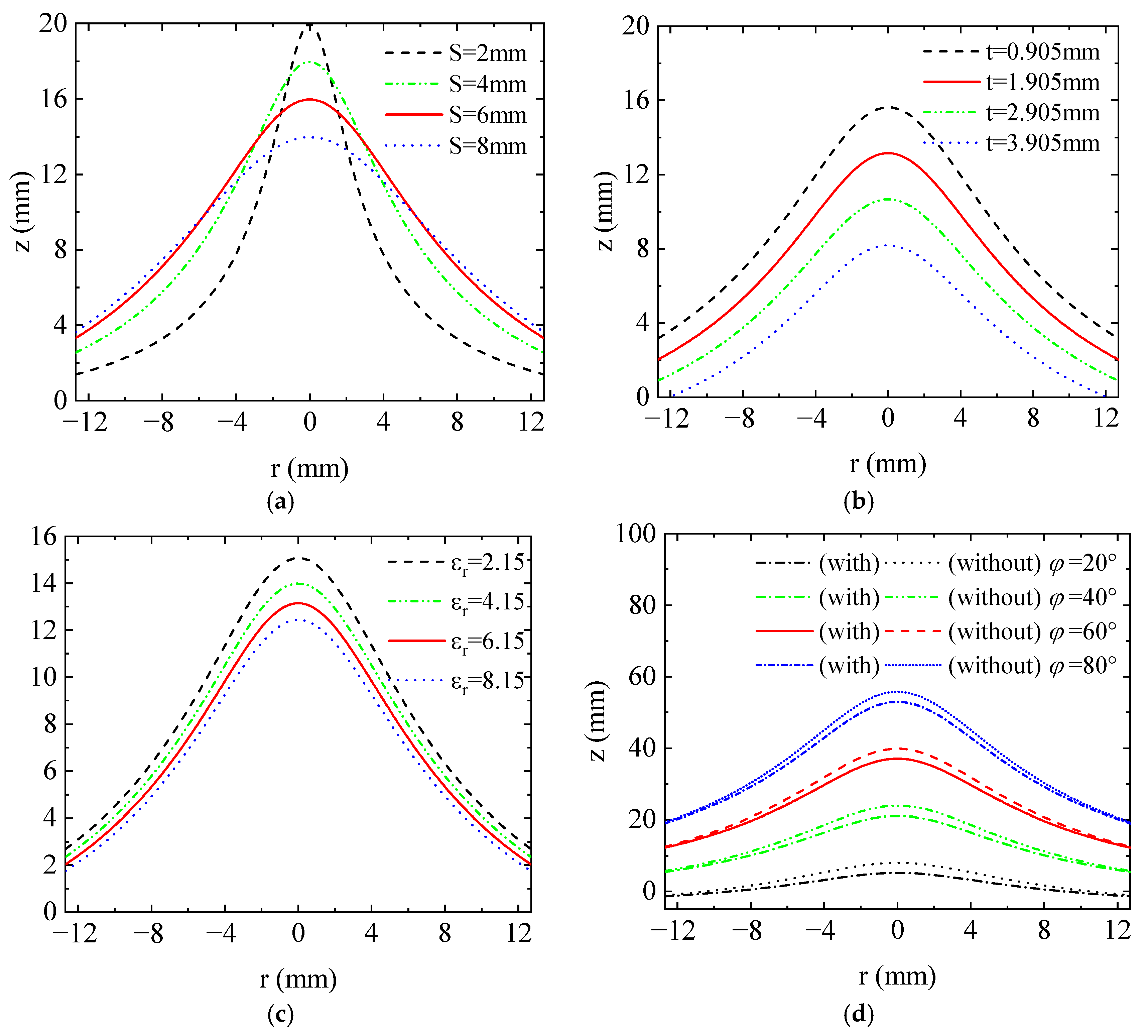
Figure 2 demonstrates the changes on the equivalent phase surface
versus different parameters of the dielectric cover.
Figure 2a shows that the equivalent phase surface is approaching the plane wave as the distance increases. Due to the limitation of the terminal spacing,
s = 6 mm is selected for the maximum directivity. The equivalent phase surfaces are also approaching the plane wave as the thickness and relative permittivity of the antenna source increase, as shown in
Figure 2b,c. With the limitation of the thickness of the terminal back cover and the restriction on the Rogers types,
t = 1.905 mm and
εr = 6.15 of Rogers 6006 are selected for the dielectric cover. By optimizing these parameters, it is feasible to enhance the gain performance of the proposed antenna.
To further evaluate the gain performance of the proposed antenna,
Figure 2d displays the equivalent phase surfaces of the antenna source with and without the dielectric cover. With the dielectric cover, the equivalent phase surface of the antenna source approximates a plane wave. The propagation through the dielectric cover can be segmented into three components: reflection, transmission, and loss within the dielectric cover. It is widely recognized that dielectric loss is primarily determined by the tanδ of the dielectric cover. However, the impact of dielectric reflection is crucial for achieving proper antenna impedance matching.
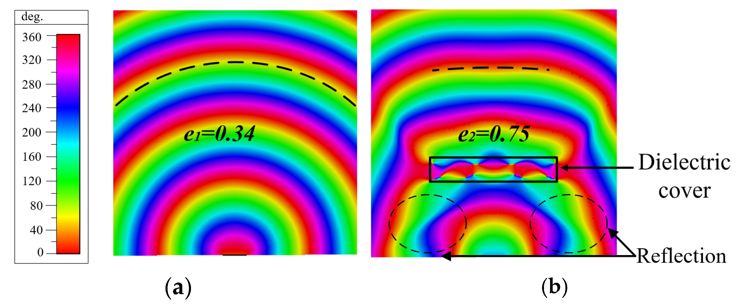
Figure 3 displays the phase distributions of the radiating source both without and with the dielectric cover in the yoz-plane at 60 GHz. It is evident that the dielectric cover impacts the equivalent phase surface by introducing reflections at the dielectric edge. The use of the dielectric cover leads to an improved approximation of the equivalent phase surface to an ellipse, achieved by increasing the centrifugal rate “e” from 0.34 to 0.75. This validates that the phase distribution over the dielectric-loaded antenna becomes more uniform, facilitating high-directivity radiation. As depicted in
Figure 3b, reflections from the edge of the dielectric cover significantly influence the phase distribution around the antenna. Consequently, the wave matrix method [
13] is employed to analyze the transmission and reflection behavior of the dielectric cover. As indicated in
Figure 1, the electromagnetic field changes from
and
to
when it penetrates through the dielectric cover with the interfaces on
,
, and
. The transmission matrix of the first interface formed by
and
can be obtained as
where
is the admittance of the dielectric cover. Similarly, the transmission matrix of the second interface
can be obtained as
The phase factor of
is
where
t is the thickness of the dielectric cover. When incorporating (9) into (10), the transmission matrix for the electromagnetic wave propagating through the dielectric cover can be expressed as follows:
It can be seen that the transmission matrix is relative to the admittance of the dielectric cover, which is reciprocal of the wave impedance.
Figure 3.
The phase distributions of the antenna source in the yoz-plane at 60 GHz (a) without the dielectric cover and (b) with the dielectric cover.
Figure 3.
The phase distributions of the antenna source in the yoz-plane at 60 GHz (a) without the dielectric cover and (b) with the dielectric cover.
Based on the aforementioned analysis, optimizing the dielectric cover has a direct impact on the wave impedance, subsequently affecting the reflection and transmission characteristics of the proposed antenna. The dielectric cover adopts the Roger6006 with a thickness of 1.905 mm,
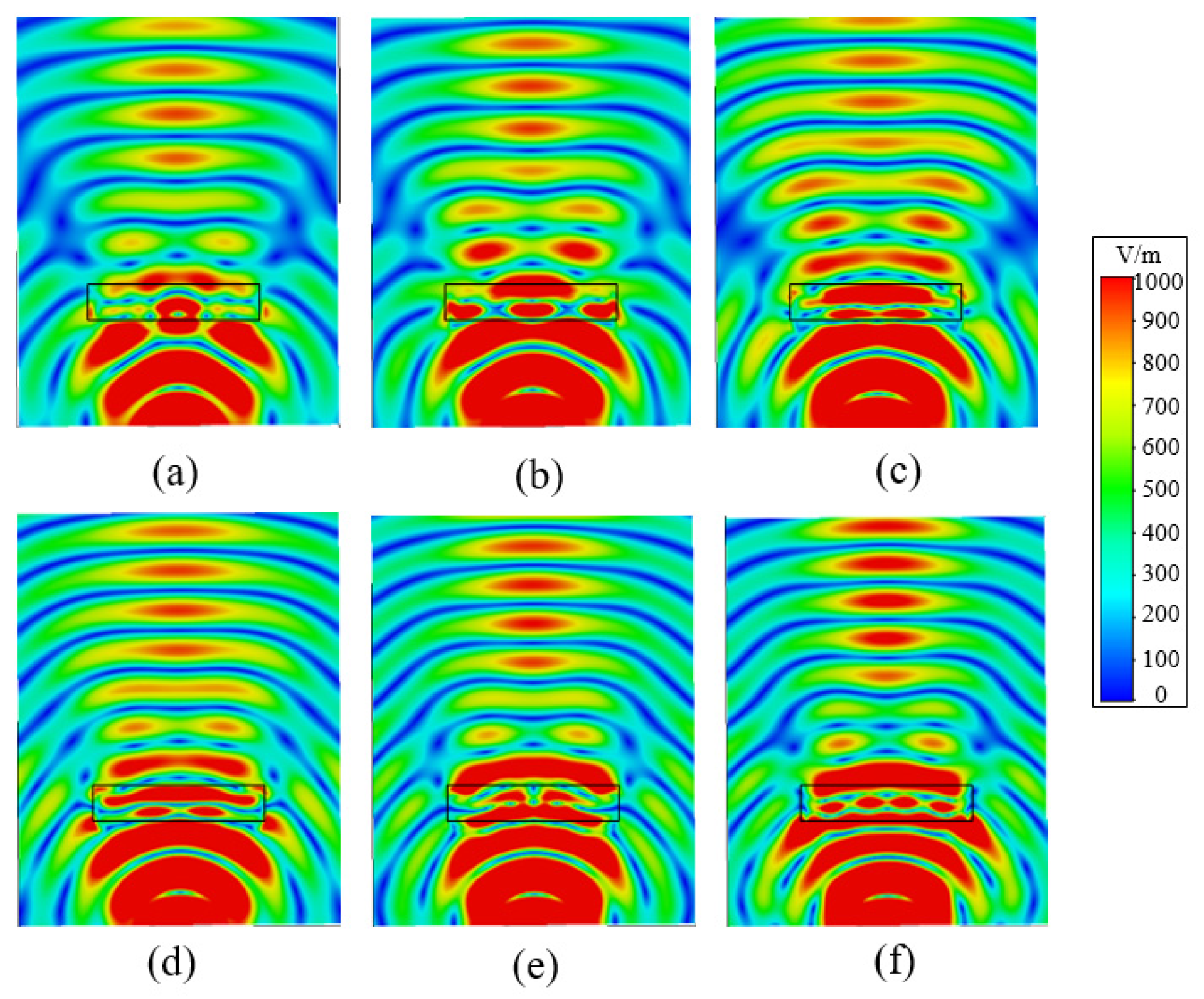
. To further validate the achievement of wideband impedance matching of the proposed antenna with the dielectric cover,
Figure 4 shows the E-fields of the antenna source in the yoz-plane spanning from 58.0 GHz to 68.0 GHz with a step length of 2 GHz. At a distance of 6 mm from the antenna to the dielectric cover, the majority of the energy efficiently transfers through the dielectric cover into free space, with minimal energy reflection across the entire operating bandwidth.
3. Antenna Configurations
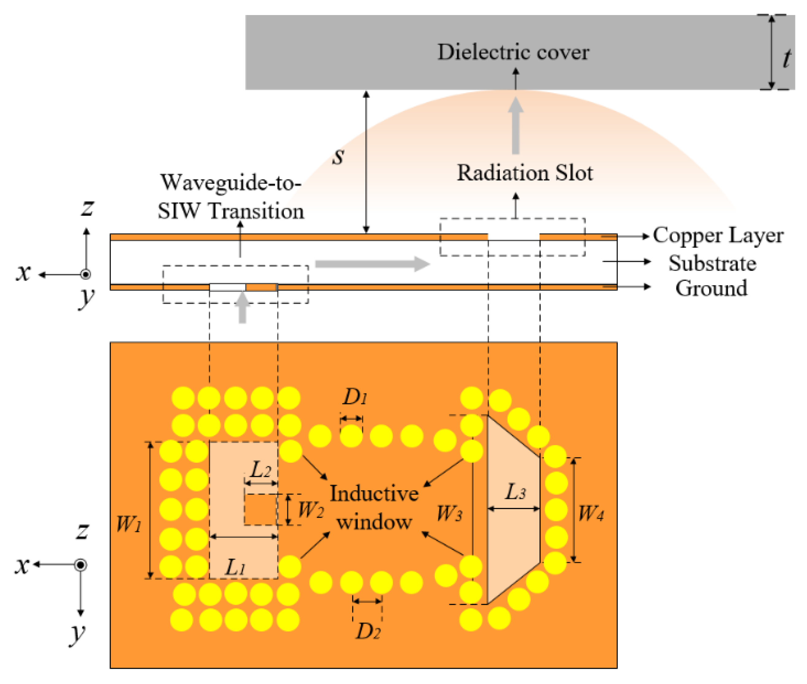
To validate the aforementioned principle, a wideband slot antenna element is introduced, as depicted in
Figure 5, providing both a side view and a top view. The proposed antenna comprises four components: the waveguide-to-SIW transition, the SIW, the ladder-shaped slot, and the dielectric cover. The waveguide-to-SIW transition is constructed using a rectangular slot etched on the ground, a copper patch, and metal vias, enabling connection to the standard WR-15 waveguide. The SIW is based on the substrate of the Rogers 5880 (
with a thickness of 0.787 mm, which achieves a simple, compact, and low-profile structure. The ladder-shaped slot is etched on the metal layer of the substrate.
The dielectric cover adopts the Rogers 6006 (
with a thickness of 1.905 mm, which is placed 6 mm above the antenna. The electromagnetic wave undergoes a vertical conversion from the standard waveguide to the waveguide-to-SIW transition, and then proceeds horizontally along the SIW. It is then radiated from the ladder-shaped slot into the air cavity and further transmitted through the dielectric cover into free space. The dimensions of the antenna elements indicated in
Figure 5 are detailed in
Table 2.
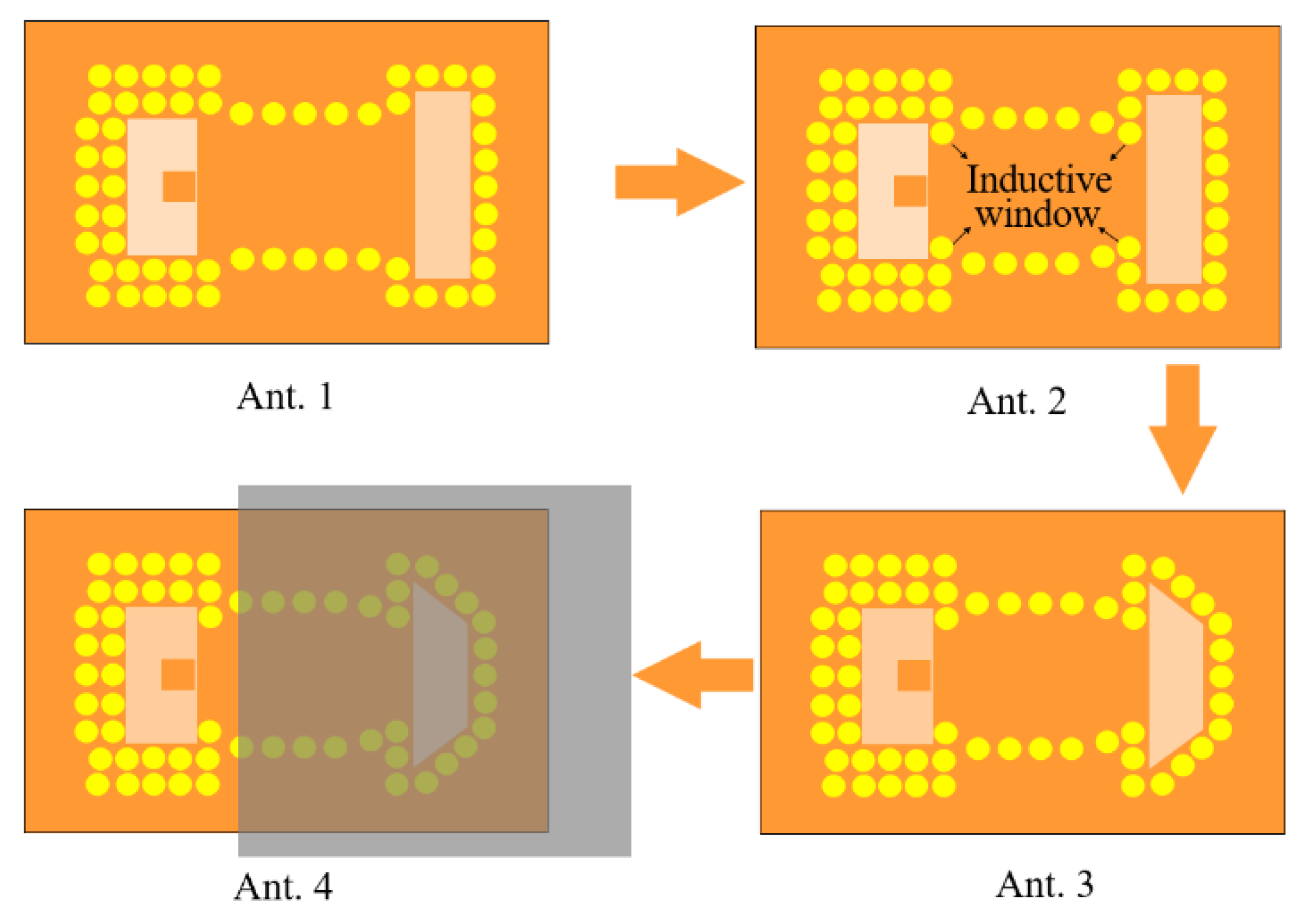
Figure 6 shows the top view of the evolution process with the proposed antenna. Ant. 1 is a conventional SIW rectangular-slot antenna, which is fed by the standard rectangular waveguide of WR-15.
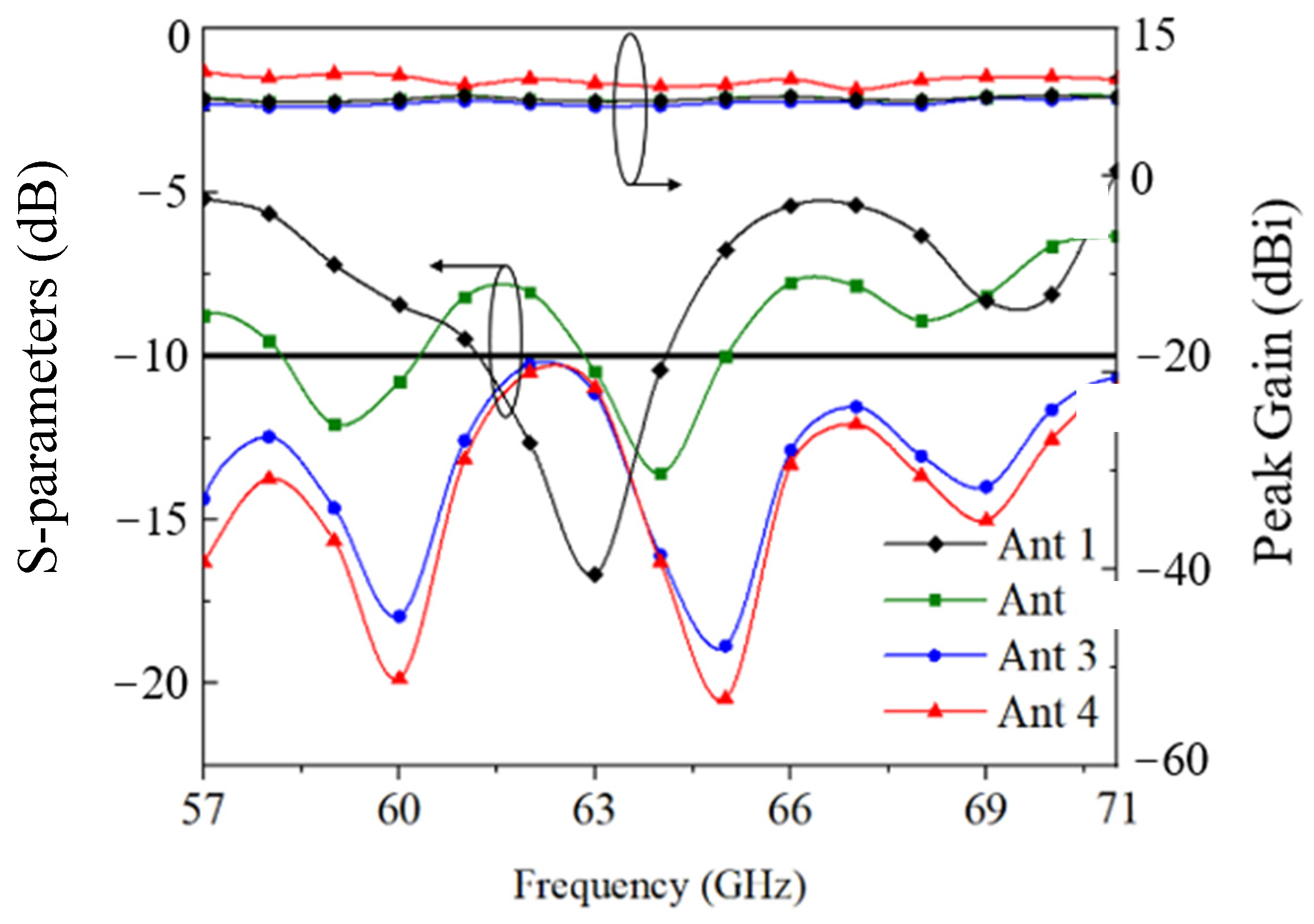
Figure 7 shows that Ant. 1 achieves the narrow bandwidth of 4.3%. To enhance its impedance bandwidth, Ant. 2 employs an inductive window, which is formed by two pairs of metal vias close to the rectangular slot etched on the ground and ladder-shaped slot, as shown in
Figure 5. The use of an inductive window can increase the resonance. With the inductive window, the input impedance is changed, and the resonances at 59.0 GHz and 64.0 GHz of the proposed antenna element are excited. However, the proposed antenna element cannot achieve impedance matching from 57.0 GHz to 71.0 GHz.
To further augment the resonance and impedance bandwidth of the proposed antenna, the slot shape is modified in the Ant. 3 design, transitioning from rectangular to ladder-shaped. With the optimization, Ant. 2 can achieve a reflection coefficient lower than −10 dB from 57.0 GHz to 71.0 GHz. compares the configurations of the antenna element with different shapes, along with the reflection coefficient and gain, as shown in
Figure 7, which indicates that the slot shape has a significant impact on the enhancement of operating band. With the inductive window and slot adjustment, the impedance bandwidth is improved from 4.3% to 21.9%. It is worth mentioning that the ladder-shaped slot antenna element makes it easier to achieve a compact structure when forming the MIMO in
Section 4. To achieve the high gain, the dielectric loading technique is applied to Ant. 4. Based on the investigation in
Section 2, Rogers 6006 is suitable to be applied as the dielectric cover with a thickness of 1.905 mm,
.
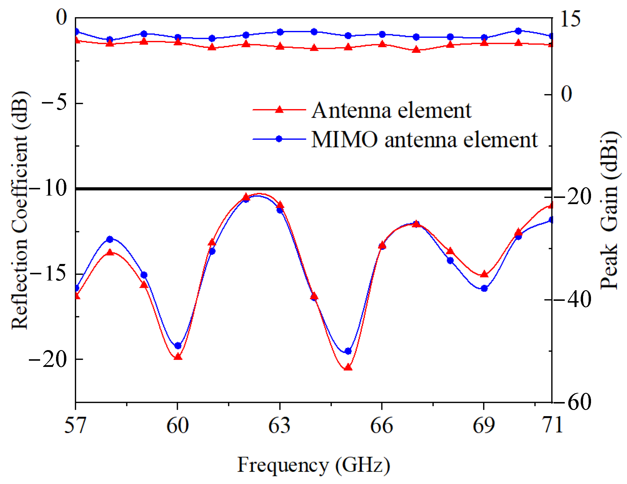
The reflection coefficient and peak gain of the antenna element, both with and without the dielectric cover, are displayed in
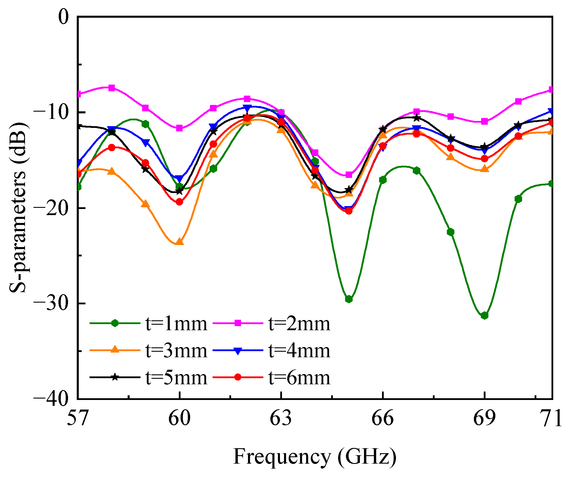
Figure 7. The antenna achieves a peak gain ranging from 7.0 dBi to 7.9 dBi without the dielectric cover. With the dielectric cover, the antenna can achieve a peak gain ranging from 8.8 dBi to 10.4 dBi. Therefore, the peak gain of the antenna element can be drastically enhanced from 7.9 dBi to 10.4 dBi in the operating band with the loading of the dielectric cover. It can be seen that the dielectric cover has little impact on the impedance performance. The impact on the impedance bandwidth of the distance between the antenna and dielectric cover is shown in
Figure 8. When the distance is greater than 3 mm (0.6
@60 GHz), the dielectric cover has little influence on the impedance matching of the proposed antenna. Compared with the microstrip antenna loaded with the superstrate in [
12], the impedance bandwidth of this ladder-shaped slot antenna is not sensitive to the distance between the antenna and dielectric cover. Taking into account both the high gain and minimal gain fluctuations, the optimized distance between the dielectric cover and the antenna is determined to be 6 mm.
4. MIMO Antenna for Enhanced Coverage
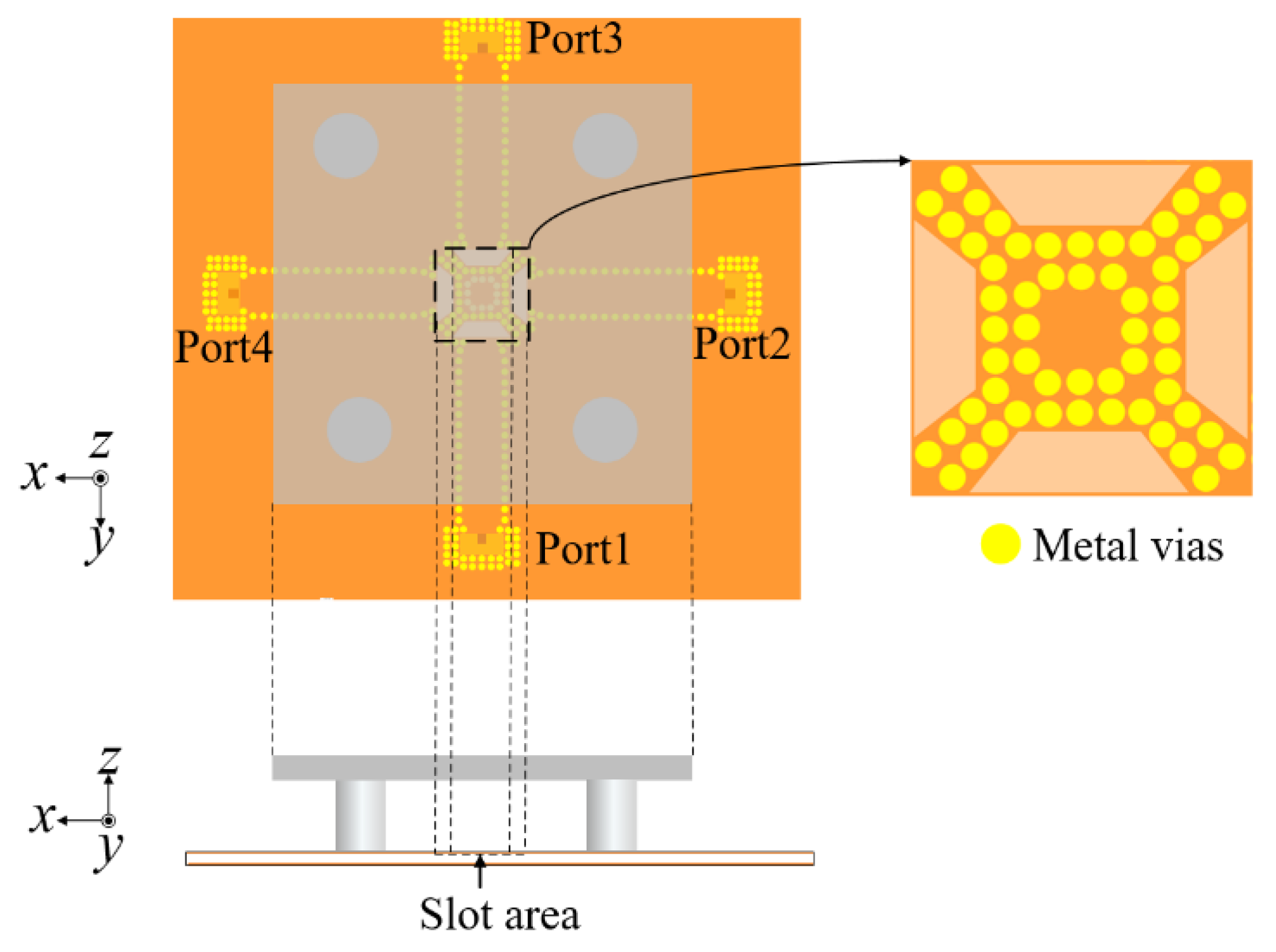
To create the MIMO antenna, four ladder-shaped slot antenna elements are strategically positioned in a configuration with central symmetry, as shown in
Figure 9. For ease of testing, the MIMO antenna is fed through standard WR-15 waveguides. The high-gain operation demonstrated in
Section 2 for the antenna element with a dielectric cover remains applicable in the MIMO antenna configuration. With the enlarged ground of the MIMO antenna, it is evident that the antenna element achieves a higher gain, with a 2.1 dB enhancement in MIMO compared to its standalone presentation (
Figure 10). The larger ground facilitates greater reflection and the superposition of the electromagnetic waves between the ground and the dielectric cover. Notably, the impedance bandwidth of the MIMO antenna closely mirrors that of the single antenna element.
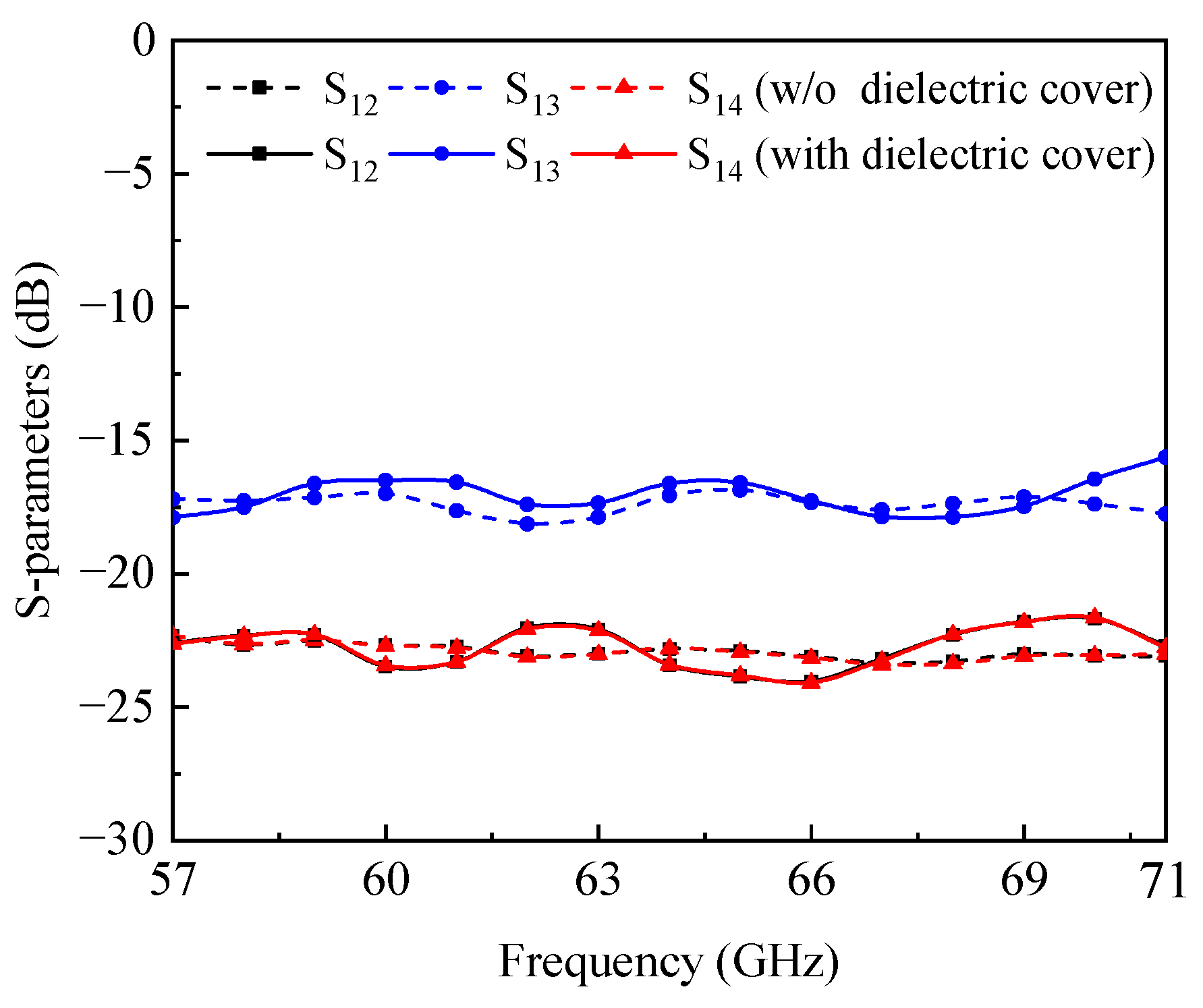
The isolation between the antenna elements plays a crucial role in influencing the performance of the MIMO antenna. Through the orthogonal arrangement of four antenna elements, adjacent elements achieve orthogonal polarization, resulting in high isolation between them. However, elements with opposing positions are unable to achieve orthogonal polarization. The presence of metal vias near the ladder-shaped slot can enhance the isolation between them. With the inclusion of metal vias, the mode excited in one antenna element is confined within the ladder-shaped cavity, exerting minimal influence on another antenna element. As illustrated in
Figure 11, the isolations between different antenna elements consistently exceed 15 dB across the entire operational bandwidth. The impact of the dielectric cover on isolation is negligible, as indicated in
Figure 11. Each antenna element functions effectively from 57.0 GHz to 71.0 GHz, respectively. By manipulating the operational state of each antenna element, the beam coverage can be easily adjusted.
Figure 12a,c show the simulated normalized 3D radiation patterns of four ports without and with the dielectric cover. The enveloped radiation patterns of the MIMO antenna with and without the dielectric cover are shown in
Figure 12b,d. With the dielectric cover, the proposed MIMO antenna has a wide high-gain coverage, as shown in
Figure 12d. When the dielectric cover is located in the center of the MIMO antenna, the position is biased relative to each antenna element. Therefore, the direction of the radiation beam has a certain oblique fire, resulting in the radiation peak and radiation null as shown in
Figure 12. In [
14], with the addition of the PRS, the radiation beams of the proposed dielectric resonator elements are tilted from the broadside direction. The proposed design achieves the tilted beam pattern by modifying both the magnitude and phased distribution through the gradation of the triangular patch. However, in this paper, the proposed antenna effortlessly achieves the tilted beam direction due to the offset position of the center of the radiation slot and the dielectric cover.
5. Fabrication and Measurement
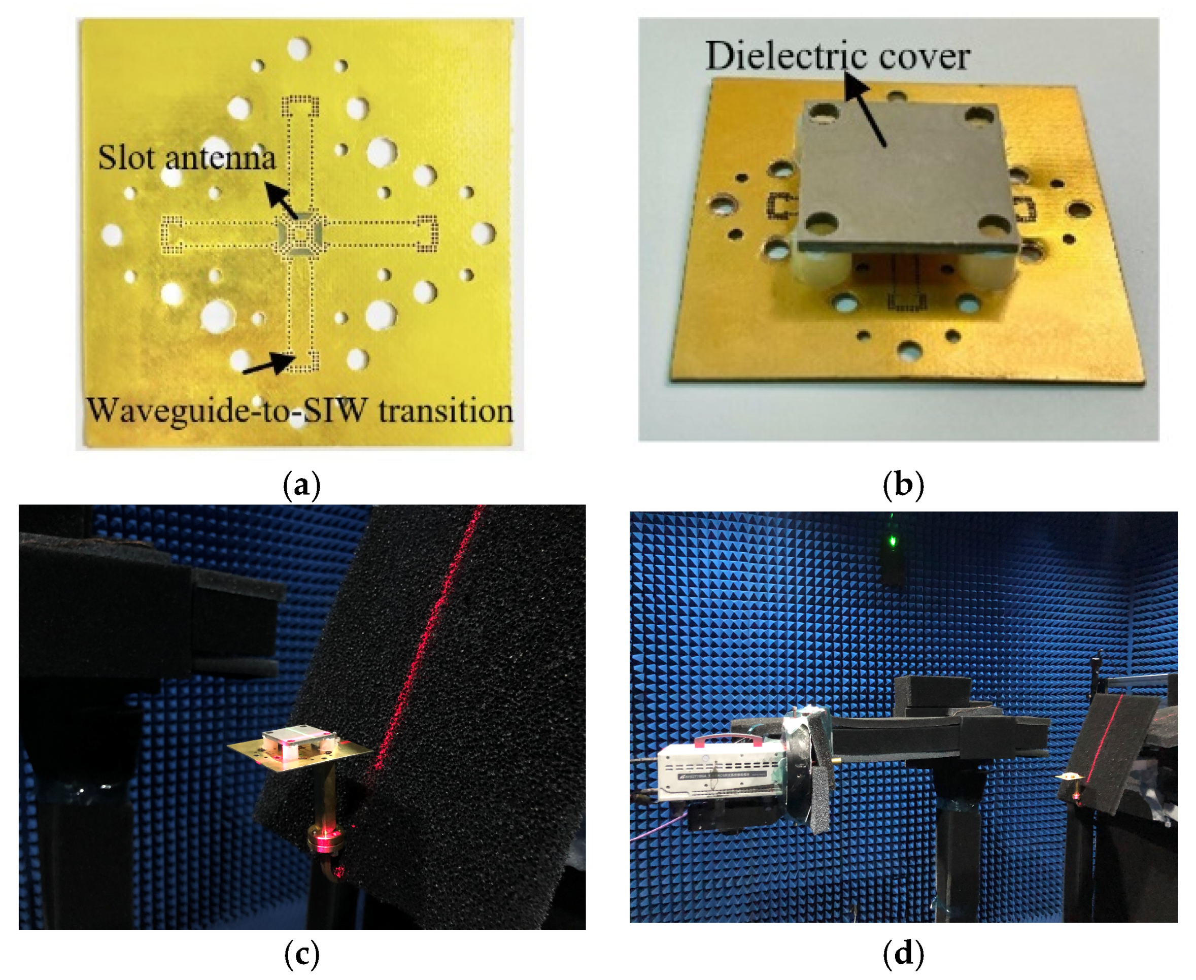
To verify the proposed design, the prototype of the 2 × 2 MIMO antenna was fabricated and measured. The conventional PCB processing was used to machine the Rogers 5880 with a thickness of 0.787 mm for the substrate and Rogers 6006 with a thickness of 1.905 mm for the dielectric cover, respectively. The photographs of the fabricated antenna without and with the dielectric cover are shown in
Figure 13a,b. It was tested in the mmWave/THz quasi-in air-based antenna measurement setup built at Shanghai Jiao Tong University, China, as shown in the
Figure 13c,d. The proposed antenna was connected to the standard WR-15 for measurement. The S-parameters were measured using a Ceyear 3672D vector network analyzer. The radiation patterns were tested using the mmWave/THz quasi-in-air-based antenna measurement setup.
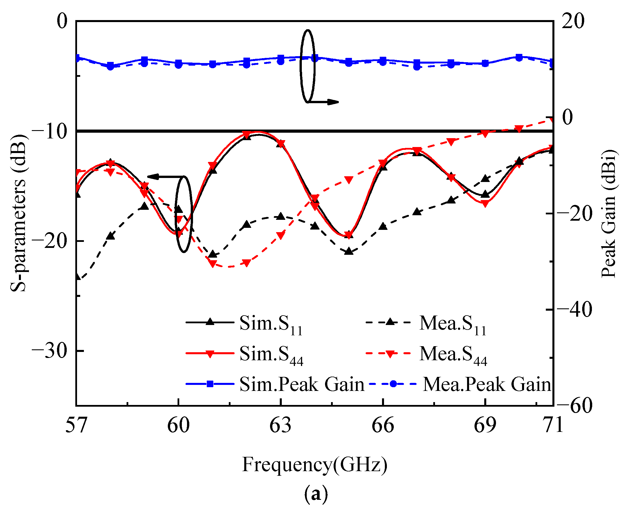
Figure 14a shows both the simulated and measured results of the reflection coefficient and peak gain. The simulation indicates that the antenna elements of the proposed antenna attain a wide impedance bandwidth of 21.9%, spanning from 57.0 GHz to 71.0 GHz. Accounting for manufacturing tolerance, the first and fourth elements achieve a measured matching impedance bandwidth of 19.0% and 21.9%, respectively. Furthermore, the simulated and measured peak gains align closely. Specifically, the simulated peak gain of the antenna element ranges from 9.8 dBi to 12.5 dBi.
From
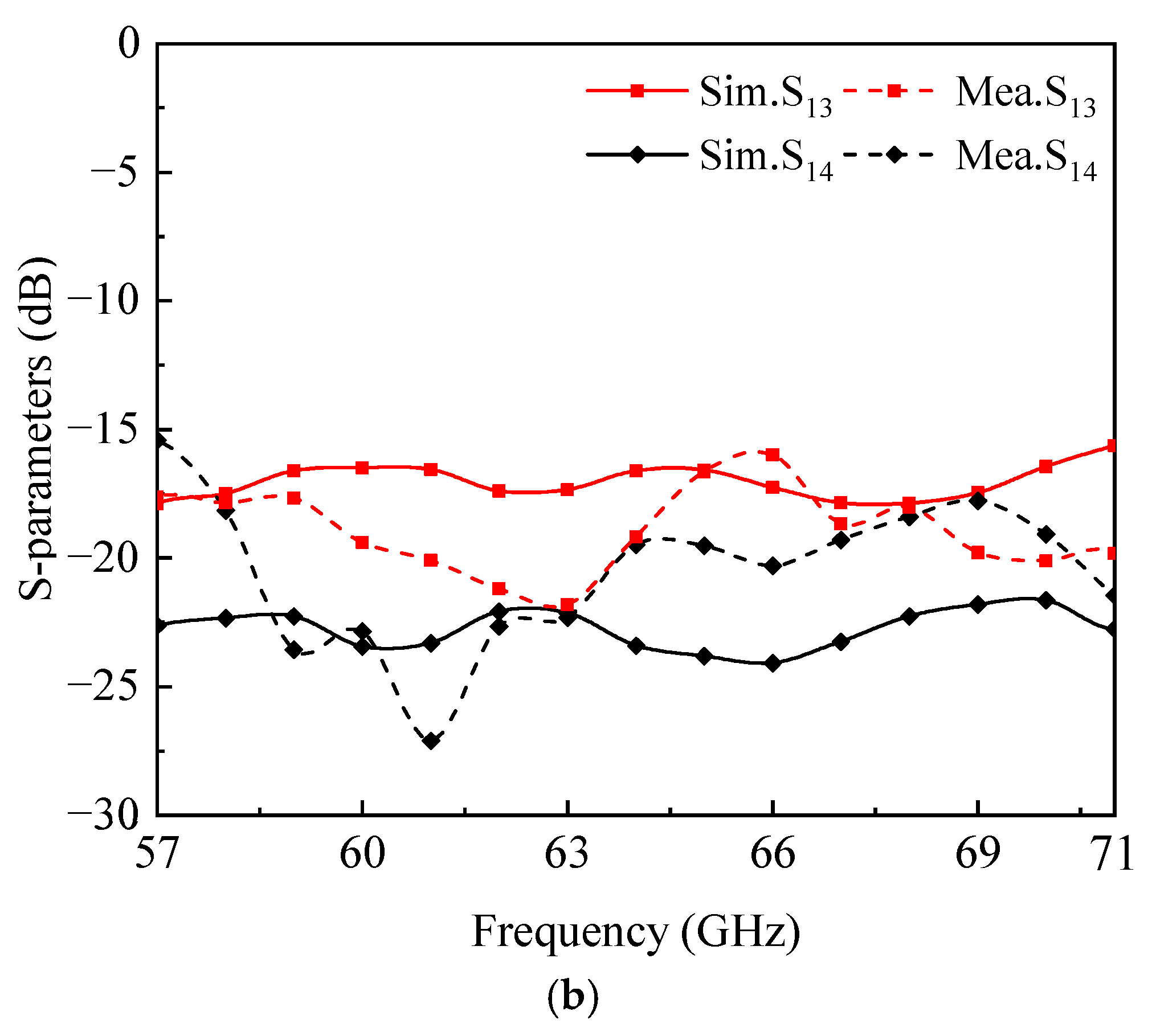
Figure 14b, it can be seen that the measured port isolations are consistently below −15 dB.
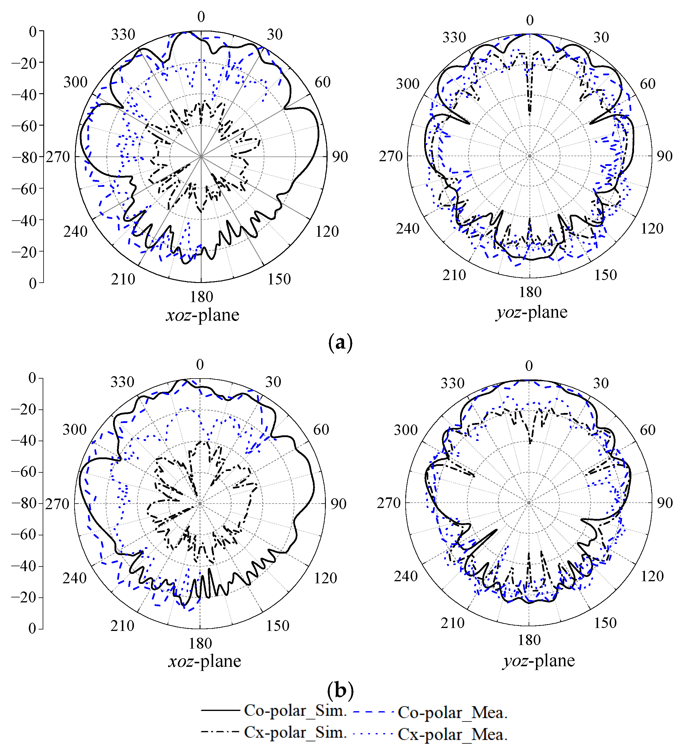
Figure 15 illustrates the radiation patterns of the proposed MIMO antenna at 60 GHz and 64 GHz. Notably, the cross-polarization level on the xoz-plane is lower compared to that on the yoz-plane, attributed to the symmetrical structure over the xoz-plane that aids in canceling out adjacent coupling. The proposed MIMO antenna effectively achieves a broadside radiation pattern. Through measurement, the proposed MIMO antenna attains a radiation efficiency of 96.2% at 60 GHz. Discrepancies between simulations and measurements primarily arise from fabrication errors. The air gap of 0.05 mm from the copper patch in the SIW-to-waveguide transition to the transmission path represents a critical structure affecting the impedance matching of the proposed antenna. Achieving precise accuracy in manufacturing proves challenging, contributing to the observed differences in simulated and measured performance.
For a comprehensive evaluation of the proposed design, a comparison with different mmWave broadside antennas is presented in
Table 3. Through phase analysis and optimization of the dielectric cover, the MIMO antenna overcomes the challenge of low gain and efficiency often encountered in mobile antennas. In a prior study [
7], a mmWave broadside antenna integrated with a phone screen exhibited a radiation efficiency of only 24.15%. To improve gain, a PRS was implemented, albeit at the cost of increased complexity. In [
8] and [
9], two mmWave antennas achieved high gains of 19.4 dBi and 16.4 dBi, respectively, utilizing PRS. However, balancing the performance of individual antenna elements in a MIMO configuration with PRS proves challenging. In comparison, the proposed MIMO antenna element, with the inclusion of the dielectric cover, achieves a peak gain of 12.3 dBi, demonstrating a competitive performance.
By employing the optimized distance between the antenna and the dielectric cover, as determined through the transmission matrix analysis, the reflection is reduced. This significantly aids the MIMO antenna in overcoming the challenge of narrow impedance bandwidth. In [
15], a mmWave microstrip antenna with a dielectric cover achieved high gain. However, the impedance bandwidth of the microstrip antenna was limited to 10.7% (57.5–64.0 GHz), falling short of covering the entire range from 57.0 GHz to 71.0 GHz. In contrast, the proposed MIMO antenna in this paper achieves a wide impedance bandwidth of 21.6% from 57.0 to 71.0 GHz, demonstrating notable improvement.
With the wideband and high-gain performance, the proposed MIMO antenna achieves isolation higher than 15 dB from 57.0 to 71.0 GHz through the help of orthogonal polarization and metal vias insertion simultaneously. With the above-mentioned advantages and compact structure, the MIMO antenna is suitable to be applied in WiGig terminal devices. The proposed MIMO antenna can be applied in mobile phone communication with its advantages of low profile, light weight, and ease to integration. Notably, the dielectric cover can also serve as a mobile phone shell, offering dual functionality: protecting internal components while simultaneously enhancing antenna performance.


