Article

Research on Sun-Oriented Spin-Stabilized Attitude Control of Micro/Nano Satellite Using Only Magnetic Control

1
Department of Precision Instrument, Tsinghua University, Beijing 100084, China
2
State Key Laboratory of Precision Measurement Technology and Instruments, Beijing 100084, China
*
Author to whom correspondence should be addressed.
Electronics 2023, 12(2), 362; https://doi.org/10.3390/electronics12020362
Submission received: 3 December 2022 / Revised: 1 January 2023 / Accepted: 6 January 2023 / Published: 10 January 2023
(This article belongs to the Special Issue Microsystems and Nano Satellites)

Abstract

:
Sun-oriented attitude control is one of the most important attitude control modes for most micro/nano satellites, which directly affects the on-orbit energy acquisition. Therefore, it is of great importance to use the simplest sensors and actuators and the most reliable algorithm to achieve sun-oriented attitude control. A sun-oriented spin-stabilized attitude control method for micro/nano satellites using only magnetic control is proposed in this paper, in which the control progress is divided into four phases: initial damping phase, sun-aligned phase, spin-up phase, and spin-stabilized phase. The influence of the shadow zone of the orbit, offset installation of sun sensor and solar panel, limitation of the field of view of the sun sensor, and environmental disturbance torques are all considered in the proposed method. The control performance is evaluated by numerical simulations, and the simulation results show that the proposed method is applicable to the satellite equipped with a sun sensor and a 3-axis magnetometer as attitude sensors and three magnetic torquers installed orthogonally as attitude actuators. The proposed method is applicable to most Earth-orbit satellites for which the geomagnetic field can provide sufficient attitude control torque.

1. Introduction

In recent years, with the development of information technology, microelectromechanical systems (MEMSs), new material technology, and high-end manufacturing, the global micro/nano satellite industry is growing rapidly and showing a “blowout” development momentum [1]. Micro/nano satellites generally refer to satellites weighing between 1 and 100 kg [2,3,4]. Due to their advantages, such as small size, light weight, low cost, flexible mobility, short development cycle, and ease to launch in batches, etc. [5,6,7,8], micro/nano satellites have become one of the most important directions of current space technology development [9]. More recently, micro/nano satellites have begun to transform from technical experiments to business operations and have gradually replaced part of traditional large satellites [10]. Micro/nano satellites have a very broad development prospect and have been widely used in many fields, such as remote sensing imaging, electronic reconnaissance, satellite communication, satellite navigation, environmental detection, and technical experiment [2,11,12,13].
For most micro/nano satellites, due to the limitations of size, cost, etc., the solar panel is fixed on the main body of the satellite and cannot be rotated. Therefore, it can only rely on the attitude determination and control system (ADCS) of the satellite to continuously adjust the satellite attitude and keep the solar panel pointing to the sun. Generally, in order to ensure a sufficient and reliable energy supply of the onboard system, the satellite needs to maintain a sun-oriented attitude for most of the time in orbit. As one of the most important satellite attitude control modes, the sun-oriented attitude is a specific satellite attitude where a certain vector fixed to the satellite is aligned with the solar vector, i.e., the unit vector pointing from the center of mass of the satellite to the sun. In many cases, whether a stable and reliable sun-oriented attitude can be achieved directly determines the success or failure of the flight mission. Therefore, it is of great importance to study how to use the simplest sensors and actuators and the most reliable algorithm to achieve the sun-oriented attitude, especially for the case that star sensor, reaction wheel, and other devices are malfunctioned.
Many studies related to sun-oriented attitude control have been carried out, and a lot of valuable research results have been obtained [14,15,16,17,18,19,20,21]. As early as 1970, E Birkhold et al. [14] studied active magnetic attitude control of the spinning sun-oriented satellite. A magnetometer and a sun sensor were selected as attitude measurement devices, and a magnetic coil installed around the spin axis was used to generate the control torques. In addition, nutation dampers were used to dampen the wobble of the satellite’s spin axis. The method is simple and has low power consumption and can be used to control the satellite to achieve a sun-oriented spin-stabilized attitude. Since then, many sun-oriented attitude control methods have been proposed. For example, in 2002, G Falbel et al. [15] proposed a spin-stabilized attitude control algorithm for CUBESAT, which is a picosatellite developed by Stanford University and the California Polytechnic State University for space experiments. CUBESAT is equipped with two orthogonal magnetic torquing coils and a CO2 high-pressure cartridge as attitude actuators and a 2-axis sun sensor as the attitude sensor. The proposed algorithm is used to control CUBESAT to maintain a spin-stabilized attitude, even during the shadow zone of the orbit. In 2007, J Luo [16] designed a spin-stabilized attitude control method for solar sail spacecraft and studied the method of generating spinning angular rate. In addition, the attitude control characteristics of the proposed method were simulated and analyzed. In 2012, aiming at the spin-stabilized satellite equipped with three magnetic coils or torque rods as attitude actuators, HS Ousaloo et al. [17] studied the control strategies of each attitude actuator. In 2019, a novel passive sun-oriented control method using solar radiation pressure torques was proposed by H Nakanishi et al. [18], which can be used as a low-cost backup for emergencies. In the same year, X Xia et al. [19] proposed a sun-oriented spin-stabilized attitude control method based on pure magnetic control for the satellite equipped with a sun sensor and a magnetometer as attitude sensors and three magnetic torquers (MTQs) as attitude actuators. The modification of the above method is also investigated in [20]. In 2020, in view of the satellite in the sun-synchronous dawn–dusk orbit, S Liu et al. [21] proposed an attitude control method from the perspective of minimal system configuration for sun orientation. The method makes full use of the satellite’s orbit characteristics and achieves the sun-oriented spin-stabilized attitude by using the pitch-axis spin-up method. However, most of the existing attitude control methods for sun orientation do not consider the influence of the shadow zone of the orbit, offset installation of sun sensor and solar panel, limitation of the field of view of the sun sensor, environmental disturbance torques, and other factors that may affect the performance of the attitude control. Therefore, the application scope of these methods is limited.
Based on the above discussions, we focus on the sun-oriented spin-stabilized attitude control for micro/nano satellites using only magnetic control. The proposed method is motivated by [19,20] while the influence of the shadow zone of the orbit, offset installation of the sun sensor and solar panel, limitation of the field of view of the sun sensor, and environmental disturbance torques are all considered in the proposed method. Different from the traditional spin-stabilized satellites (their spinning angular rate is generally as high as tens of revolutions per minute, even hundreds of revolutions per minute [22]), the proposed method can be applied to the case that the satellite spins at a relatively low angular rate (about several degrees per second). The proposed method is applicable to most Earth-orbit satellites for which the geomagnetic field can provide sufficient attitude control torque. The numerical simulation results show that the proposed method is applicable to the micro/nano satellite equipped with a sun sensor and a 3-axis magnetometer (TAM) as attitude sensors and three MTQs installed orthogonally as attitude actuators. In addition, the proposed method effectively guarantees the smooth implementation of satellite equipment debugging, energy acquisition, and other flight missions. Even in space exploration missions, the proposed method can be used as a good primary or backup solution for some phases of these missions [23,24,25,26].
The paper is organized as follows. In Section 2, the overview and mathematical model of micro/nano satellite’s ADCS are introduced. Then, the sun-oriented spin-stabilized attitude control method is proposed in Section 3 including the rate filter design and the attitude controller design. The numerical simulation and results analysis are presented in Section 4. Finally, the conclusion is summarized in Section 5.

2. Problem Formulation

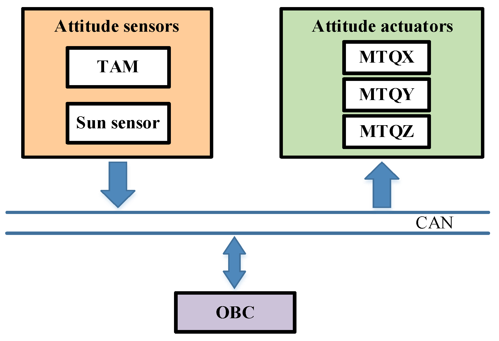
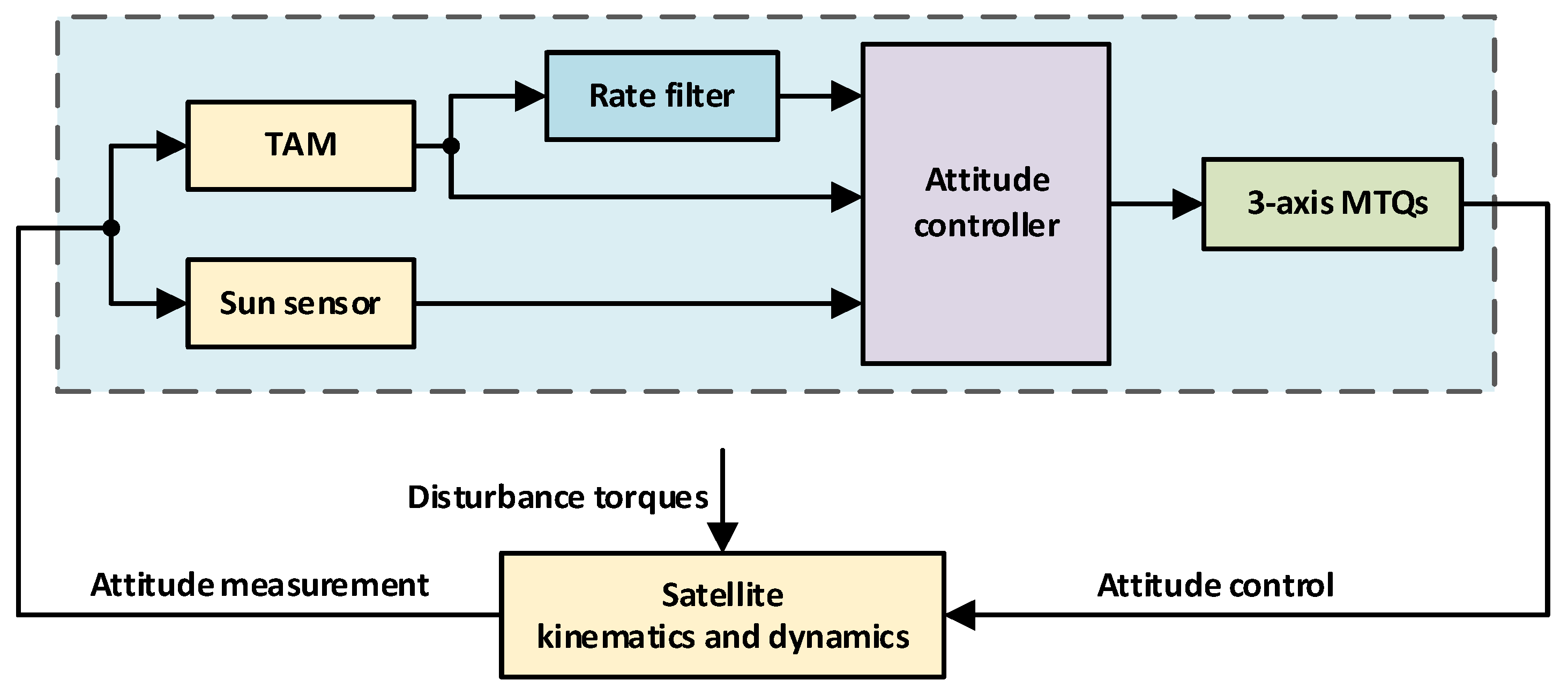
2.1. System Overview

The ADCS of the micro/nano satellite studied in this paper is composed of three parts: attitude sensors, attitude actuators, and an on-board computer (OBC) on which the ADCS control algorithm runs.
The attitude actuator of the ADCS consists of a 3-axis MTQs (here, three MTQs installed orthogonally were treated as one device). The attitude sensors of the ADCS consist of a TAM and a sun sensor. The ADCS control algorithm is responsible for generating the control command and recording all the necessary data of the ADCS. As shown in Figure 1, attitude sensors, attitude actuators, and OBC are connected via the controller area network (CAN) bus, which is an international standardized serial communication protocol.

2.2. Kinematics and Dynamics Models

The mathematical model of satellite attitude motion contains a kinematics model and a dynamics model [27]. The coordinate systems used in this paper are first introduced, where the Earth-centered inertial coordinate system is O i X i Y i Z i , and the micro/nano satellite centroid inertial spindle coordinate system is O b X b Y b Z b . The symbol Q b i = q 0 q T T = q 0 q 1 q 2 q 3 T is used to denote the attitude from O b X b Y b Z b to O i X i Y i Z i . The symbol ω b i b = ω x ω y ω z T is used to denote the angular rate of the satellite relative to the inertial space, and the superscript b means that the vector is represented in the coordinate system O b X b Y b Z b .
The kinematics equation of the system is as follows and describes the relationship between the attitude quaternion Q b i and the angular rate ω b i b :
Q ˙ b i   =   1 2 H ( Q b i   ) 0 ω b i b T T ,
where the square matrix H ( Q b i ) is an orthogonal matrix, which satisfies H ( Q b i ) H ( Q b i ) T = I 4 :
H ( Q b i )   = q 0 q 1 q 2 q 3 q 1 q 0 q 3 q 2 q 2 q 3 q 0 q 1 q 3 q 2 q 1 q 0 .
In this paper, the micro/nano satellite is regarded as a rigid body. According to the angular momentum theorem, the satellite satisfies the following equation [27]:
J ω b i b ˙ + ω b i b × ( J ω b i b ) = T M T + d ,
where J is the rotational inertia matrix of the satellite, and it is a positive definite matrix; ω b i b is the angular rate of the satellite relative to the inertial space; T M T is the control torque of the 3-axis MTQs, and d is the sum of the external disturbance torques acting on the satellite. This is the dynamics equation of the satellite, which mainly describes the relationship between the angular rate ω b i b and T M T , d . For the satellite centroid inertial spindle coordinate system O b X b Y b Z b , the rotational inertia matrix J has the following form:
J = diag J x , J y , J z ,
where J x , J y , and J z are the rotational inertia of the satellite around O b X b , O b Y b , and O b Z b axes, respectively.
This paper focuses on attitude control under bounded external disturbance torques. Therefore, d satisfies the following assumption:
Assumption 1: The sum of the external disturbance torques d in (3) is bounded; i.e., there always exists a constant ε + such that d ε .

2.3. Control Objective

For the satellite equipped with a sun sensor and a TAM as attitude sensors, the solar vector cannot be obtained in the shadow zone of the orbit, which makes it difficult to achieve a sun-oriented attitude in the shadow zone of the orbit. The spinning of the satellite provides an effective way to solve this problem [27]. According to the angular momentum theorem, the orientation of the spin axis of the satellite in the inertial space will remain unchanged when the satellite is free from external torque or the external torque is small. Sun-oriented spin-stabilized attitude control is a specific satellite attitude control mode, in which the satellite spins around a given vector fixed to the satellite, and the spin axis is aligned with the solar vector at the same time; i.e.,
S t b = e b ω b i b = ω s p i n S t b ,
where e b is the given vector fixed to the satellite; S t b is the unit vector pointing from the satellite to the sun, and ω s p i n is a given spinning angular rate.

3. Control Algorithm Design

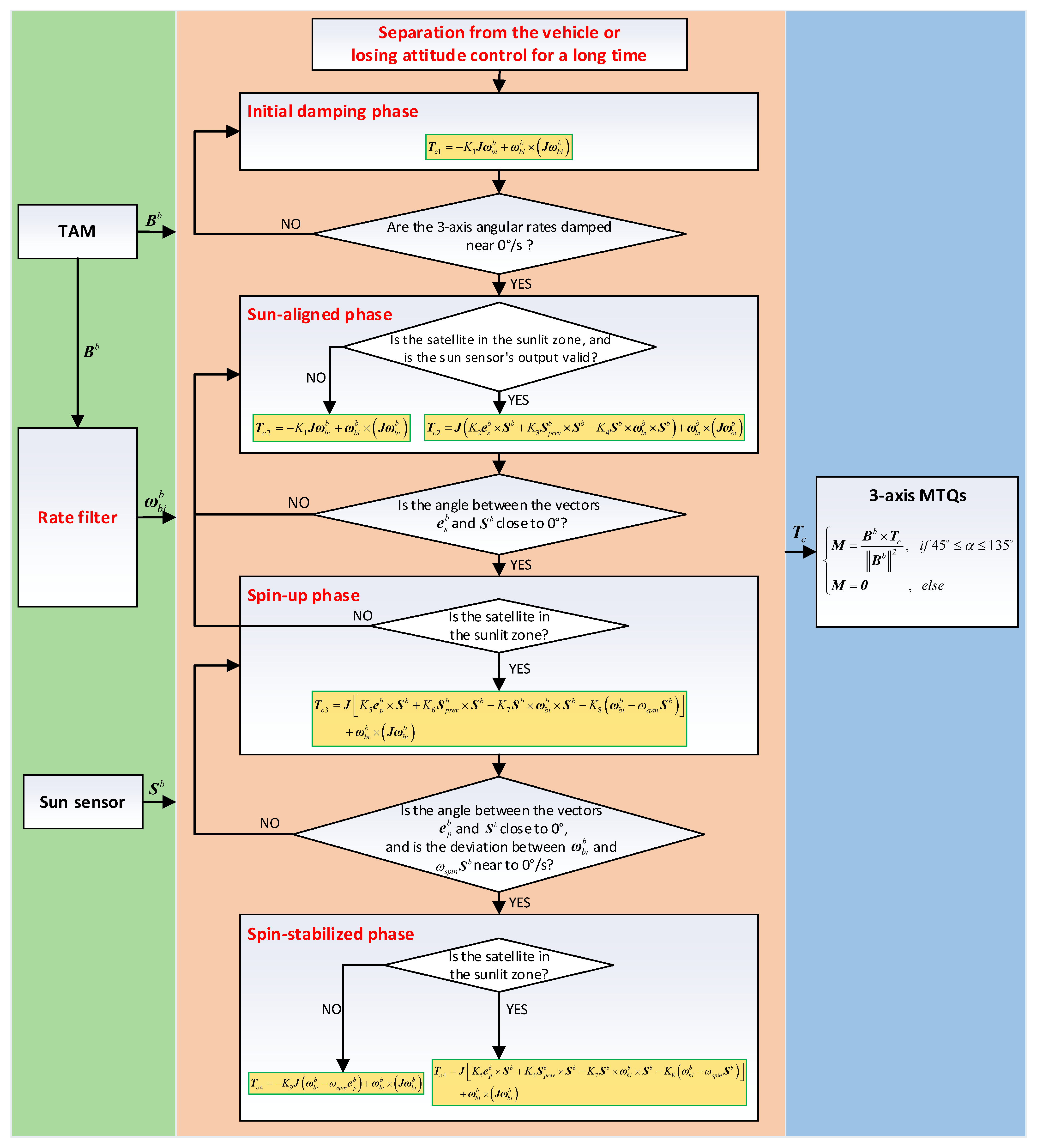
3.1. Sun-Oriented Spin-Stabilized Attitude Control

For the ADCS shown in Figure 1 with the simplest configuration, the sketch of the attitude control method proposed in this paper is shown in Figure 2, which can be used as the safe mode of the satellite.
The TAM installed on the main body of the satellite obtains the measured value of the geomagnetic field. Then, the output of the TAM is used by the rate filter to estimate the 3-axis angular rates of the satellite. According to the measurement data of the geomagnetic field and the estimated value of the satellite’s 3-axis angular rates, the attitude controller calculates the control torque and transforms it into the control commands of the 3-axis MTQs. In addition, the measurement output of the sun sensor is also used to calculate the control torque. Finally, the magnetic torquers execute the generated control commands and then control the satellite to achieve the sun-oriented spin-stabilized attitude.

3.2. Rate Filter Design

In this paper, a fast and rough rate filter is used to estimate the 3-axis angular rates of the satellite, which is a classical angular rate information estimation method [28]. The rate filter belongs to a class of the extended Kalman filter (EKF), which uses the measured value of the TAM as input to estimate the 3-axis angular rates of the satellite. The rate filter is widely used in the aerospace field because of its advantages of less computation and stable operation [29]. We next present the details of the rate filter.
The state vector x R a t e 3 of the rate filter is taken as the angular rate ω b i b of the satellite relative to the inertial space [30]:
x R a t e = ω b i b = ω x ω y ω z ,
where ω x , ω y , and ω z are the components of ω b i b along O b X b , O b Y b , and O b Z b axes, respectively.
Expanding the dynamics model (3) into component expression gives:
ω ˙ x = T M T , x + d x J x + J y J z J x ω y ω z ω ˙ y = T M T , y + d y J y + J z J x J y ω z ω x ω ˙ z = T M T , z + d z J z + J x J y J z ω x ω y ,
where, T M T , x , T M T , y , and T M T , z are the components of T M T along O b X b , O b Y b , and O b Z b axes, respectively, and d x , d y , and d z are the components of d along O b X b , O b Y b , and O b Z b axes, respectively [27]. Discretizing the above equation by first-order accuracy schemes, the transition matrix Φ R a t e 3 × 3 can be obtained:
Φ R a t e = 1 J y J z J x ω z Δ T J y J z J x ω y Δ T J z J x J y ω z Δ T 1 J z J x J y ω x Δ T J x J y J z ω y Δ T J x J y J z ω x Δ T 1 ,
where Δ T is the sampling period of the filter.
Denote the measured value obtained by the TAM at the current sampling time as B b = B x b B y b B z b T 3 , and denote the measured value obtained by the TAM at the previous sampling time as B p r e v b = B p x b B p y b B p z b T 3 . Then, the measurement vector Z R a t e 3 of the rate filter is taken as the difference between two adjacent measured values of the TAM:
Z R a t e = B b B p r e v b = B x b B p x b B y b B p y b B z b B p z b .
Because the sampling period Δ T is small relative to the orbital period, the variation of the geomagnetic field vector at the location of the satellite in Δ T can be ignored. Therefore, it can be approximated that the difference between B b and B p r e v b is only affected by the attitude motion of the satellite. Let Θ Δ = Δ T · ω b i b 3 be the vector expression of the rotation angle of the satellite in Δ T . Because the rotation angle is relatively small during Δ T , the direction cosine matrix C Δ 3 × 3 corresponding to Θ Δ can be approximated as [31]:
C Δ I 3 Δ T ω b i b × ,
where I 3 3 × 3 is an identity matrix, and ω b i b × is a cross product matrix defined as follows:
ω b i b × = 0 ω z ω y ω z 0 ω x ω y ω x 0 .
It then follows from (9) and (10) that:
Z R a t e = C Δ B p r e v b B p r e v b = 0 ω z Δ T ω y Δ T ω z Δ T 0 ω x Δ T ω y Δ T ω x Δ T 0 B p x b B p y b B p z b = 0 B p z b Δ T B p y b Δ T B p z b Δ T 0 B p x b Δ T B p y b Δ T B p x b Δ T 0 ω x ω y ω z .
This is regarded as the measurement equation of the rate filter. Then, the measurement matrix H R a t e 3 × 3 can be obtained:
H R a t e   = 0 B p z b Δ T B p y b Δ T B p z b Δ T 0 B p x b Δ T B p y b Δ T B p x b Δ T 0 .
Finally, the 3-axis angular rates could be estimated according to the general EKF method [30].

3.3. Attitude Controller Design

The attitude controller of the proposed sun-oriented spin-stabilized attitude control method in this paper consists of four control phases: initial damping phase, sun-aligned phase, spin-up phase, and spin-stabilized phase.

3.3.1. Initial Damping Phase

Considering that the satellite may have uncertain angular momentum after separation from the vehicle (or losing attitude control for a long period of time), the satellite enters the initial damping phase first, during which the 3-axis MTQs work to slow down the 3-axis angular rates of the satellite.
In the initial damping phase, the desired control torque T c 1 3 outputted by the controller is given by the following equation:
T c 1 = K 1 J ω b i b + ω b i b × J ω b i b ,
where K 1 is the control coefficient greater than zero. The first part of T c 1 is used to slow down the 3-axis angular rates of the satellite, and the second part is used to eliminate the effects of angular rate coupling of different axes.
The desired control torque T c 1 will be outputted by the 3-axis MTQs, and then the objective of angular rate damping is realized. When the 3-axis angular rates are damped near 0°/s, the controller enters the next phase, namely the sun-aligned phase.

3.3.2. Sun-Aligned Phase

After completing angular rate damping, the satellite enters the sun-aligned phase. During this phase, the satellite is controlled to converge to the state that the optical axis of the sun sensor is aligned with the solar vector by using the measurement data of the sun sensor.
Because 3-axis MTQs can only output the control torque perpendicular to the geomagnetic field vector, the attitude maneuvering ability of the satellite is insufficient. Therefore, at the beginning of the sun-aligned phase, the control law of the initial damping phase continues to be used to search the sun slowly while damping the angular rate of the satellite, until the sun enters the sun sensor’s field of view.
When the sun enters the field of view of the sun sensor, motivated by [32], the desired control torque T c 2 3 outputted by the controller is designed as follows:
T c 2 = J K 2 e s b × S b + K 3 S p r e v b × S b K 4 S b × ω b i b × S b + ω b i b × J ω b i b ,
where K 2 , K 3 , and K 4 are the control coefficients, and all of them are greater than zero; e s b represents the unit vector along the optical axis of the sun sensor, which is determined by the installation angle of the sun sensor; S b is the unit vector pointing from the satellite to the sun measured by the sun sensor at the current sampling time, and S p r e v b is the unit vector pointing from the satellite to the sun measured by the sun sensor at the previous sampling time. The main objective of the control torque T c 2 is to align the optical axis of the sun sensor with the sun. The first part of T c 2 is used to make sure that e s b is aligned with S b . The second part and the third part are used to dampen the angular rate component perpendicular to S b . The fourth part is used to eliminate the effects of angular rate coupling of different axes. It should be noted that if the field of view of the sun sensor is larger than 90°, the first part of T c 2 can be modified to:
K 2 e s b × S b , i f     0 ° β 90 ° K 2 e s b × S b e s b × S b , e l s e ,
where β is the angle between the vectors e s b and S b .
Then, the desired control torque T c 2 will be outputted by the 3-axis MTQs. When the angle between the vectors e s b and S b is close to 0°, the controller enters the next phase, namely the spin-up phase.

3.3.3. Spin-Up Phase

During this phase, since the sun sensor’s optical axis is already roughly aligned with the sun, the satellite is controlled so that the designated plane of the satellite (e.g., solar panel plane) is perpendicular to the solar vector, and the satellite begins to spin-up around the normal vector of the designated plane. The desired control torque T c 3 3 outputted by the controller is given by the following equation:
T c 3 = J K 5 e p b × S b + K 6 S p r e v b × S b K 7 S b × ω b i b × S b K 8 ω b i b ω s p i n S b + ω b i b × J ω b i b ,
where K 5 , K 6 , K 7 , and K 8 are positive control coefficients; e p b represents the unit normal vector of the designated plane, and ω s p i n is a given spinning angular rate. In contrast to T c 2 , whose control objective is to align e s b with the solar vector, the control objective of T c 3 is to align e p b with the solar vector and make the satellite spin around e p b . Similar to the sun-aligned phase, if the angle between the vectors e p b and S b is larger than 90°, the first part of T c 3 can be modified by referring to Equation (16). In particular, in order to obtain a better control effect, when the angle between e s b and e p b is large relative to the field of view of the sun sensor, the spin-up phase can be divided into two subphases. In the first subphase, the normal vector of the designated plane is controlled to align with the solar vector. Then, the satellite is controlled to spin up in the second subphase.
The control scheme designed in this paper, which first makes the optical axis of the sun sensor align with the sun and then makes the normal vector of the designated plane align with the sun, can significantly improve the reliability and stability of satellite attitude control in the case of limitation of the field of view of the sun sensor.
Then, the desired control torque T c 3 will be outputted by the 3-axis MTQs. When the angle between the vectors e p b and S b is close to 0°, and the deviation between the estimated value of the satellite’s 3-axis angular rates and ω s p i n S b is near to 0°/s, the controller enters the next phase, namely the spin-stabilized phase. However, if the satellite flies into the shadow zone of the orbit during this phase, it needs to return to the sun-aligned phase.

3.3.4. Spin-Stabilized Phase

In this phase, when the satellite is in the sunlit zone of the orbit, the calculation formula of the desired control torque T c 4 3 is the same as that of T c 3 , i.e., Equation (17). When the satellite is in the shadow zone of the orbit, due to the angular momentum along the spin axis of the satellite, the sun-oriented attitude is maintained during the shadow zone of the orbit, so that the normal vector of the designated plane is aligned with the solar vector as the satellite returns to the sunlit zone of the orbit. In order to ensure that the spinning angular rate of the satellite is always near the given value ω s p i n , the desired control torque of the controller during the shadow zone of the orbit is given by the following equation:
T c 4 = K 9 J ω b i b ω s p i n e p b + ω b i b × J ω b i b ,
where K 9 is the control coefficient larger than zero. Then, the desired control torque T c 4 will be outputted by the 3-axis MTQs.
We next prove the stability of the closed-loop system with the proposed control method and the attitude control of the sunlit zone of the orbit in the spin-stabilized phase is taken as an example without loss of generality. The control errors of the controller (17) are defined as:
e 1 = S b e p b e 2 = ω b i b ω s p i n S b .
Theorem 1.
Consider the attitude control system of the microsatellite described by the nonlinear dynamics (3) and the controller (17). Suppose that Assumption 1 holds and the initial conditions of the controller satisfy e 2 < ε K 8 min ( J x , J y , J z ) , the control error e 2 is uniformly ultimately bounded (UUB).
Proof of Theorem 1.
The proof is based on the Lyapunov stability theory. Define a candidate Lyapunov function for e 1 and e 2 as:
V ( t ) = 0.5 K 5 e 1 T e 1 + 0.5 e 2 T e 2 .
The unit vector S b satisfies S b = C i b S i , where C i b is the direction cosine matrix between coordinate systems O i X i Y i Z i and O b X b Y b Z b , and S i is the solar vector represented in the coordinate system O i X i Y i Z i . The approximation is that S i ˙ = 0 , and then we obtained that S b ˙ = S b × ω b i b [31]. Then,
V ˙ ( t ) = K 5 e 1 T e ˙ 1 + e 2 T e ˙ 2 = K 5 S b e p b T S b × ω b i b + ω b i b ω s p i n S b T ω b i b ˙ ω s p i n S b × ω b i b = K 5 e p b T S b × ω b i b + ω b i b ω s p i n S b T ω b i b ˙ .
According to Equations (3) and (17), it follows that:
ω b i b ˙ = K 5 e p b × S b + K 6 S p r e v b × S b K 7 S b × ω b i b × S b K 8 ω b i b ω s p i n S b + J 1 d .
Substituting (22) into (21), we obtain:
V ˙ ( t ) = K 5 e p b T S b × ω b i b K 8 ω b i b ω s p i n S b 2 + ω b i b ω s p i n S b T J 1 d + ω b i b ω s p i n S b T K 5 e p b × S b + K 6 S p r e v b × S b K 7 S b × ω b i b × S b = K 5 e p b T S b × ω b i b + K 5 ω b i b T e p b × S b + ω b i b T K 6 S p r e v b × S b K 7 S b × ω b i b × S b K 8 e 2 2 + e 2 T J 1 d ,
where S p r e v b × S b can be approximately written as:
S p r e v b × S b = S p r e v b S b × S b = S b ˙ Δ T × S b = 1 Δ T S b × ω b i b × S b .
Obviously, it follows that ω b i b T K 6 S p r e v b × S b K 7 S b × ω b i b × S b 0 . At the same time, according to the cross product rule, we know that e p b T S b × ω b i b = ω b i b T e p b × S b . Then,
V ˙ ( t ) K 8 e 2 2 + e 2 T J 1 d e 2 K 8 e 2 + ε min ( J x , J y , J z ) .
It follows that V ˙ ( t ) < 0 if e 2 > ε K 8 min ( J x , J y , J z ) . Therefore, V ( t ) is strictly monotonous decreasing when e 2 is outside the region D e 2 e 2 ε K 8 min ( J x , J y , J z ) , and ultimately ensures that e 2 enters the region D . Once e 2 enters the region D , we know that e 2 will remain in the region D afterward according to the fact that V ˙ ( t ) < 0 . Therefore, it can be concluded that the control error e 2 is UUB and will eventually converge to the region D [33]. It can be then proven that e 1 is also bounded. In practical applications, the upper bound of the control errors can be controlled in an acceptable range by selecting appropriate control coefficients. To this end, the proof is completed.

3.4. Control Command Generation

Based on the desired control torque output by the attitude controller, the expected magnetic moment M 3 outputted by the 3-axis MTQs can be calculated by the following equation:
M = B b × T c B b 2 , i f   45 ° α 135 ° M = 0                 , e l s e ,
where T c is the desired control torque outputted by the attitude controller; i.e., T c 1 , T c 2 , T c 3 , or T c 4 , and α is the angle between the vectors B b and T c . Finally, the magnetic moment M will be transformed into the control commands that the 3-axis MTQs can execute, and then the objective of the attitude controller is realized.
In summary, after the accomplishment of the initial damping phase, the sun-aligned phase, and the spin-up phase, the satellite finally enters the spin-stabilized phase, which is the long-term operating mode of the satellite. The detailed control flow of the sun-oriented spin-stabilized attitude control method proposed in this paper is shown in Figure 3.

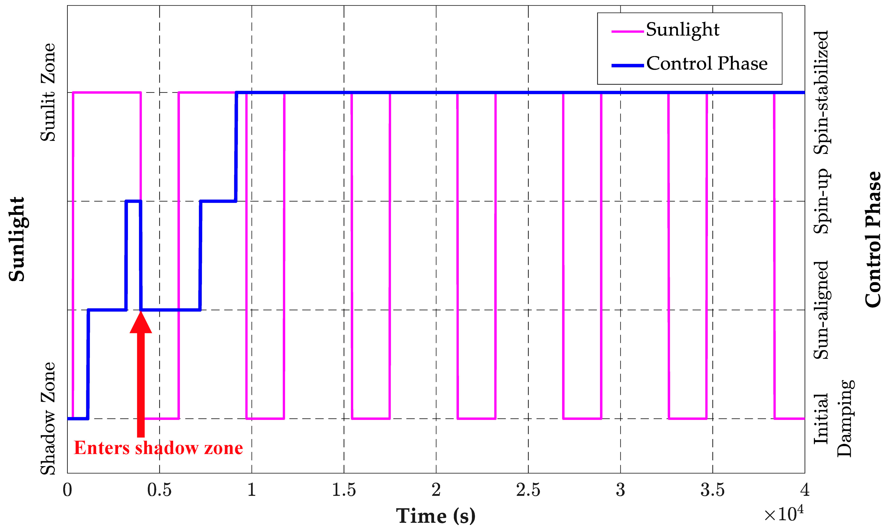
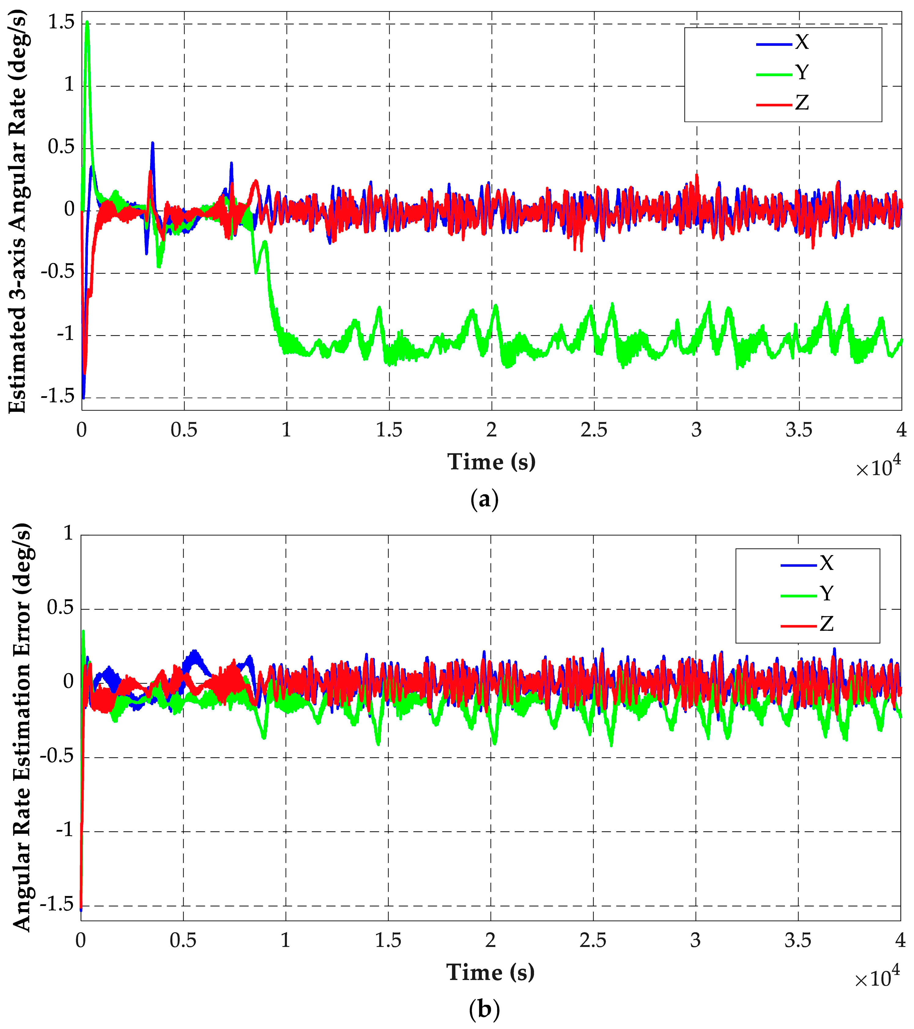
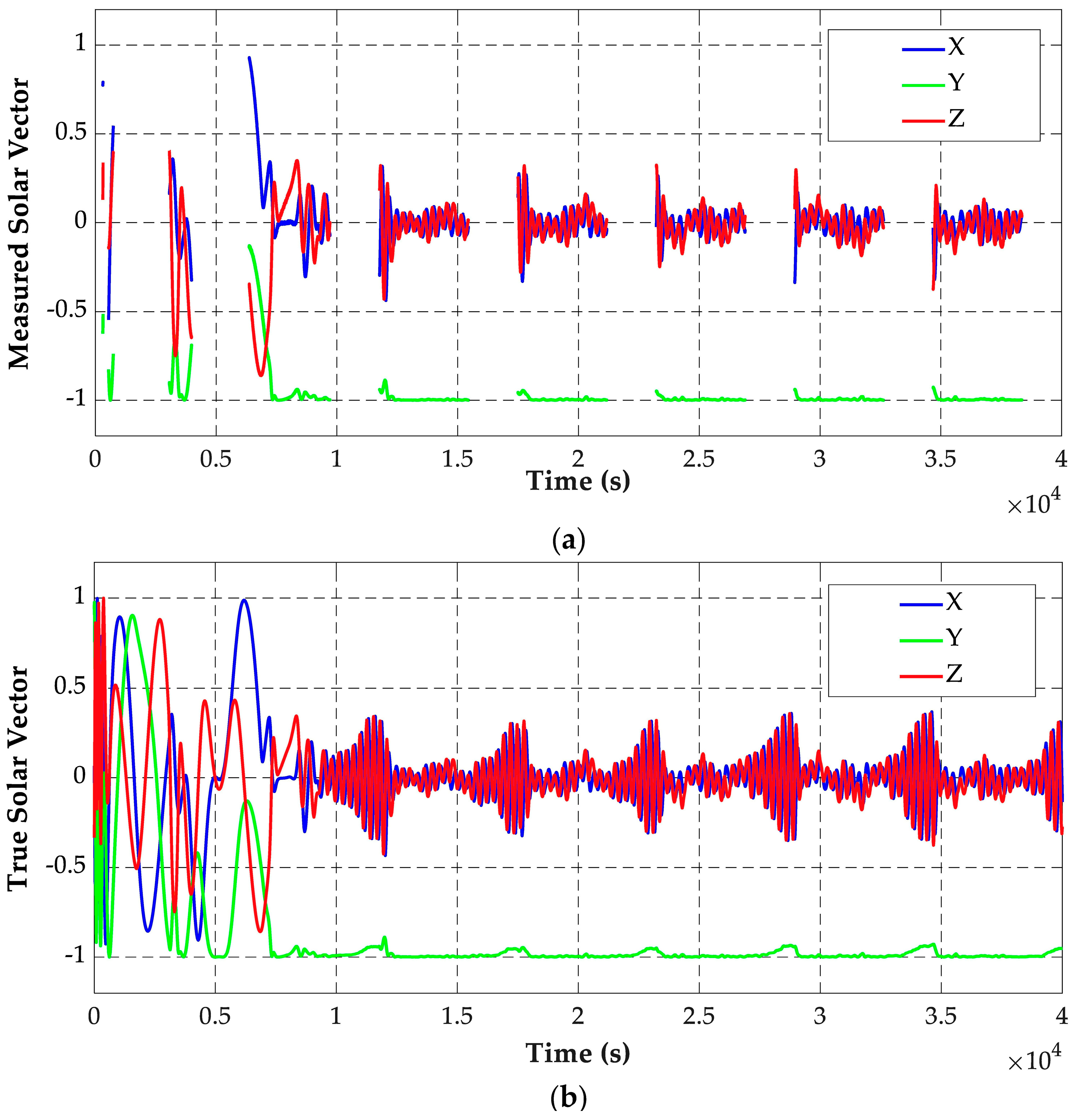
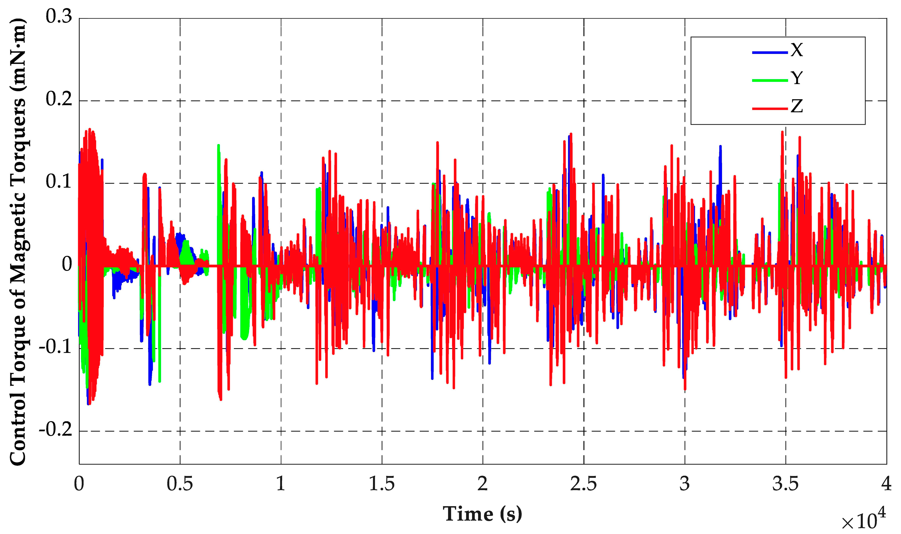
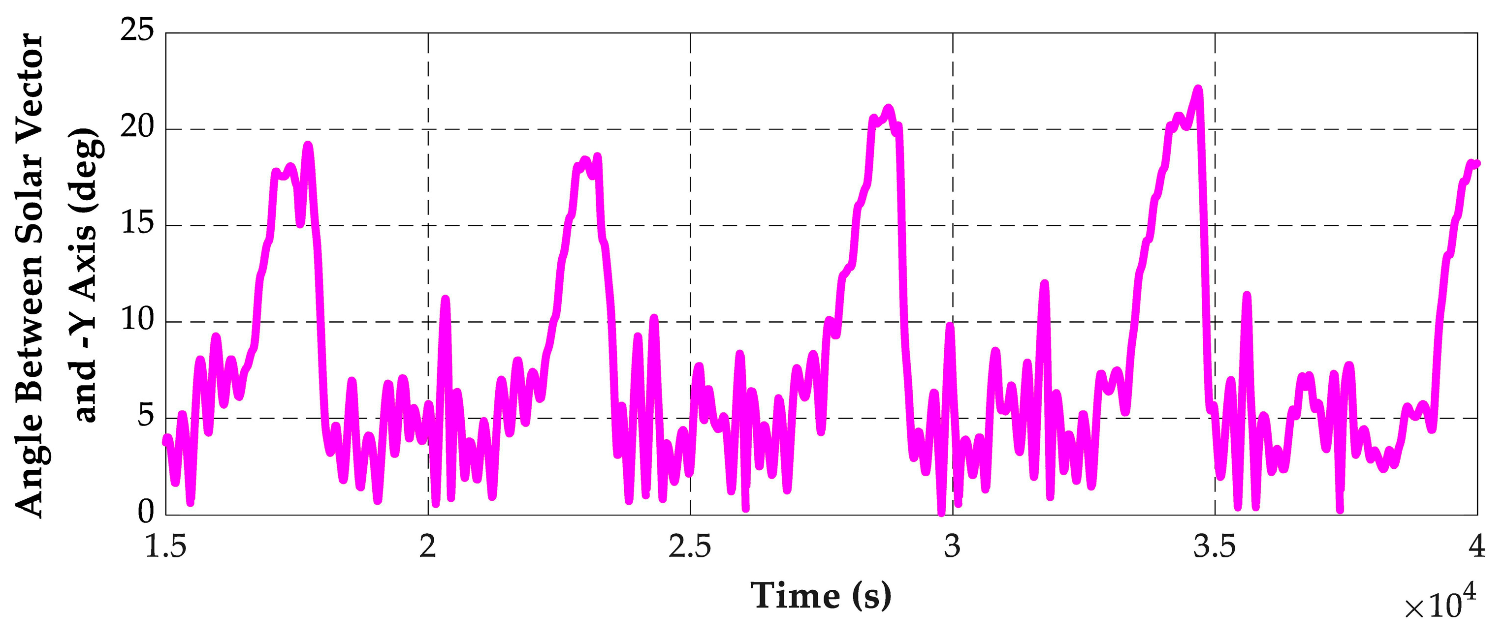
4. Numerical Simulation

In order to verify the effectiveness of the proposed control method, the numerical simulation analysis is performed by using MATLAB Simulink. The closed-loop simulation program consists of the onboard software module and the satellite model module. The onboard software module is used to simulate the ADCS software that operates on the OBC, which is compiled and run by MATLAB. Its input data include attitude sensor measurement and attitude actuator status, and the output data are control commands of 3-axis MTQs. The satellite model module calculates the attitude data of the simulated satellite based on the mathematical models, such as the dynamics model, kinematics model, sensor measurement model, and disturbance torque model. The input of this module is orbit parameters, magnetic field, and control commands of 3-axis MTQs, and the output is the simulated sensors’ measurement.
The simulated satellite runs in a sun-synchronous orbit with an orbit altitude of 545 km and a descending node local time of 10:30. The solar panel of the simulated satellite is installed toward the O b Y b axis. At the same time, the solar panel is also the designated plane of the satellite that needs to point to the sun in the spin-stabilized phase. In order to ensure that the sun is in the field of view of the sun sensor under the ground-oriented attitude, such as remote sensing imaging, the sun sensor is installed at a certain angle away from the O b Y b axis. The angles between the optical axis of the sun sensor and the O b X b , O b Y b , and O b Z b axes of the satellite are set to be 69.2952°, 150°, and 110.7048°, respectively. The field of view of the sun sensor is 90° × 110°. The angle between the optical axis of the sun sensor and the normal vector of the designated plane is up to 30°, so the spin-up phase is divided into two subphases as mentioned in Section 3.3.3 in the simulation.
Considering that the satellite may have uncertain angular momentum and the attitude is also in a random state after separation from the vehicle (or losing attitude control for a long period of time), the initial 3-axis angular rates are assumed to be [−1.5  −1.5  −1.5]°/s, and the initial attitude angles are assumed to be [160  20  60]°. The simulation parameters are based on a microsatellite that is being developed, and Table 1 shows the detailed simulation parameters. The given spinning angular rate ω s p i n is chosen as 1.146°/s (about 0.02   r a d / s ).
The control period is set to be 0.5 s in the simulation. The attitude controller of the proposed method in this paper has 9 control coefficients in total, and their values used in the simulation are shown in Table 2.
The simulation results of the sunlight occlusion where the satellite is located and the satellite control phase are shown in Figure 4. The initial damping phase lasts for nearly 1130 s. The 3-axis angular rates of the satellite are between −0.2°/s and 0.2°/s at the end of this phase (Figure 5a). Then, ADCS enters the sun-aligned phase and begins to search for the sun. At about 3060 s, the sun enters the field of view of the sun sensor (Figure 6a). After about 130 s, ADCS enters the spin-up phase and begins to spin up around the O b Y b axis. However, the satellite flies into the shadow zone of the orbit at 3980 s, and the satellite must return to the sun-aligned phase. At 6370 s, the sun enters the field of view of the sun sensor again (Figure 6a). After a series of attitude control, the satellite finally enters the spin-stabilized phase at about 9170 s, which is the long-term operating mode of the satellite. The simulation results show that the satellite can keep the sun-oriented attitude steadily after entering the spin-stabilized phase. Most notably, with the difference of satellite characteristic parameters, orbit parameters, initial attitude, and control coefficients, the variation curve of the control phase will be different.
Figure 4. The variation curve of the sunlight occlusion where the satellite is located and the satellite control phase.
Electronics 12 00362 g004
Figure 5. Simulation results of (a) 3-axis angular rates of the satellite estimated by rate filter; (b) angular rates estimation errors of rate filter.
Electronics 12 00362 g005
Figure 6. Measured (a) and true (b) solar vectors.
Electronics 12 00362 g006
The 3-axis angular rates of the satellite estimated by the rate filter and its estimation errors are shown in Figure 5. According to statistics, the mean value and standard deviation of rate filter estimation errors are [−0.00105  −0.134  −0.00388]°/s and [0.0797  0.0785  0.0681]°/s.
Figure 6 shows the solar vector measured by the sun sensor and the true solar vector; both are represented in the coordinate system O b X b Y b Z b . The O b X b -axis and O b Z b -axis components of the solar vector have obvious oscillations, which is mainly due to the nutation of the satellite while spinning. Especially in the shadow zone of the orbit, the satellite cannot obtain the solar vector and control the direction of the spin axis, so nutation becomes more intense during this period.
Figure 7 shows the control torque outputted by the 3-axis MTQs. When the satellite flies from the shadow zone to the sunlit zone, the control torque increases to reduce the satellite nutation.
Figure 7. Control torque outputted by 3-axis MTQs.
Electronics 12 00362 g007
The control error at steady state, i.e., the angle between the solar vector and the O b Y b axis, is shown in Figure 8. The angle begins to increase gradually when the satellite flies into the shadow zone of the orbit and decreases when the satellite flies into the sunlit zone of the orbit. The error angle is basically within 10° in the sunlit zone of the orbit, which meets the basic flight mission requirements of most satellites, such as energy acquisition. However, in the shadow zone of the orbit, the maximum error angle reaches about 20°. This is because the angle between the solar vector and the O b Y b axis cannot be measured in the shadow zone. At the same time, it should be noted that the control error may vary with the satellite’s characteristic parameters, orbital parameters, initial attitude, and control coefficients.
Figure 8. Angle between the solar vector and the O b Y b axis.
Electronics 12 00362 g008

5. Conclusions

A sun-oriented spin-stabilized attitude control method using only magnetic control is proposed in this paper, in which the control progress is divided into four phases: initial damping phase, sun-aligned phase, spin-up phase, and spin-stabilized phase. The advantages of the control method proposed in this paper are reflected in three aspects. Firstly, it can realize the sun-oriented attitude in the presence of the shadow zone of the orbit, which overcomes the shortcomings that most of the existing studies can only be applied to the dawn–dusk orbit. Secondly, the proposed method only uses an offset-installed sun sensor with a limited field of view to measure the solar vector, which makes most of the satellites meet the conditions for the application of the method. Thirdly, a detailed control process from the initial damping phase to the spin-stabilized phase is designed in the proposed method, which greatly improves the practicability of the method. The proposed control method is applicable to most Earth-orbit satellites for which the geomagnetic field can provide sufficient attitude control torque and can control the satellite to achieve the sun-oriented attitude from any initial state. The simulation results show that the proposed method effectively ensures the smooth implementation of satellite equipment debugging, energy acquisition, and other flight missions.

Author Contributions

Conceptualization, B.Y. and Z.M.; methodology, B.Y.; software, B.Y. and D.Y.; validation, Z.M. and D.Y.; formal analysis, B.Y.; writing—original draft preparation, B.Y.; writing—review and editing, Z.M. and D.Y.; visualization, B.Y.; project administration, B.Y.; funding acquisition, Z.M. All authors have read and agreed to the published version of the manuscript.

Funding

This work has been supported in part by the Beijing Natural Science Foundation under Grant JQ20013 and in part by the National Natural Science Foundation of China under Grant 61833009.

Data Availability Statement

The data used to support this study are included within the article.

Conflicts of Interest

The authors declare no conflict of interest.

References

  1. World’s Largest Database of Nanosatellites, almost 3500 Nanosats and CubeSats. Available online: https://www.nanosats.eu (accessed on 1 August 2022).
  2. Li, J.; Wang, Q.; Zhang, S.; Zhao, Z. Analysis on development trends of foreign country’s micro/nano satellites in earth observation. Spacecr. Eng. 2020, 29, 126–132. [Google Scholar]
  3. Man, X. Analysis on the development situation of China’s micro/nano satellite industry. Satell. Appl. 2019, 2, 34–38. [Google Scholar]
  4. Ma, J. A Design of Micro/Nano Satellite Simulator. Master’s Thesis, Jilin University, Jilin, China, 2021. [Google Scholar]
  5. Nakasuka, S.; Miyata, K.; Tsuruda, Y.; Aoyanagi, Y.; Matsumoto, T. Discussions on Attitude Determination and Control System for Micro/Nano/Pico-Satellites Considering Survivability Based on Hodoyoshi-3 and 4 Experiences. Acta Astronaut. 2018, 145, 515–527. [Google Scholar] [CrossRef]
  6. Feruglio, L.; Corpino, S. Neural Networks to Increase the Autonomy of Interplanetary Nanosatellite Missions. Robot. Auton. Syst. 2017, 93, 52–60. [Google Scholar] [CrossRef]
  7. Hu, X.; Zhao, Y.; Chen, X.; Lattarulo, V. Conceptual Moon Imaging Micro/Nano-Satellite Design Optimization under Uncertainty. Acta Astronaut. 2018, 148, 22–31. [Google Scholar] [CrossRef]
  8. Li, Z.; Li, J.; Schmit, T.J.; Wang, P.; Lim, A.; Li, J.; Nagle, F.W.; Bai, W.; Otkin, J.A.; Atlas, R.; et al. The Alternative of CubeSat-Based Advanced Infrared and Microwave Sounders for High Impact Weather Forecasting. Atmos. Ocean. Sci. Lett. 2019, 12, 80–90. [Google Scholar] [CrossRef]
  9. Bouwmeester, J.; Guo, J. Survey of Worldwide Pico- and Nanosatellite Missions, Distributions and Subsystem Technology. Acta Astronaut. 2010, 67, 854–862. [Google Scholar] [CrossRef]
  10. Lu, Z. Status and Trends of the Small Satellite and Micro/nano Satellites. J. Ordnance Equip. Eng. 2018, 39, 1–7. [Google Scholar]
  11. Shi, R.; Li, X.; Deng, K. Development situation of micro/nano satellite and its application in optical reconnaissance. Aerosp. Electron. Warf. 2016, 32, 8–13. [Google Scholar]
  12. Nakasuka, S.; Sako, N.; Sahara, H.; Nakamura, Y.; Eishima, T.; Komatsu, M. Evolution from Education to Practical Use in University of Tokyo’s Nano-Satellite Activities. Acta Astronaut. 2010, 66, 1099–1105. [Google Scholar] [CrossRef]
  13. Yamada, K.; Nagano, H. Development of a Heat Storage Panel for Micro/Nano-Satellites and Demonstration in Orbit. Appl. Therm. Eng. 2015, 91, 894–900. [Google Scholar] [CrossRef]
  14. Birkhold, E.; Leiss, F.; Stopfkuchen, K. An Active Magnetic Attitude Control System for a Spinning Sun Oriented Satellite. In Proceedings of the 3rd IFAC Symposium on Automatic Control in Space, Friedrichshafen, Germany, 2–6 March 1970. [Google Scholar]
  15. Falbel, G.; Puig-Suari, J.; Peczalski, A. Sun Oriented and Powered, 3 Axis and Spin Stabilized CubeSats. In Proceedings of the Aerospace Conference, Big Sky, MT, USA, 9–16 March 2002. [Google Scholar]
  16. Luo, J. Study on Attitude Control of Solar Sail Spacecraft. Master’s Thesis, Harbin Institute of Technology, Harbin, China, 2007. [Google Scholar]
  17. Ousaloo, H.S.; Badpa, A. Magnetic Attitude Control System for Spin Stabilized Satellite. In Proceedings of the 20th Iranian Conference on Electrical Engineering (ICEE 2012), Tehran, Iran, 15–17 May 2012. [Google Scholar]
  18. Nakanishi, H.; Takagi, R.; Oda, M. Dynamics Analysis of Weathercock like Passive Sun-Oriented Control Using Solar Pressure. Trans. JPN. Soc. Aeronaut. Space Sci. Aerosp. Technol. JPN. 2019, 17, 483–490. [Google Scholar] [CrossRef]
  19. Xia, X.; Guo, C.; Chen, H.; Xu, W.; Zhang, K.; Zhou, S. A Spinning Sun Oriented Method Based on Pure Magnetic Control. China Patent 109649693, 21 January 2019. [Google Scholar]
  20. Xia, X.; Zhang, K.; Guo, C.; Chen, H.; Zhou, S.; Xu, W. An Improved Spinning Sun Oriented Method Based on Pure Magnetic Control Using Geomagnetic Field Measurement Data. China Patent 109677638, 30 January 2019. [Google Scholar]
  21. Liu, S.; Guo, C.; Gao, H.; Wang, J. A Kind of Attitude Control Method of the Satellite on the Morning–Dusk Sun Synchronization Orbit for Sun Acquisition. Aerosp. Control. 2020, 38, 14–18. [Google Scholar]
  22. Zanardi, M.C.; Celestino, C.C.; Borderes Motta, G.; França, E.M.; Garcia, R.V. Analysis of Analytical Attitude Propagators for Spin-Stabilized Satellites. Comput. Appl. Math. 2018, 37, 96–109. [Google Scholar] [CrossRef]
  23. Mikhail, Y.O. Interplanetary Small-Satellite Missions: Ballistic Problems and Their Solutions. Gyroscopy Navig. 2021, 12, 281–293. [Google Scholar]
  24. Stefano, C. Design of fuel-saving lunar captures using finite thrust and gravity-braking. Acta Astronaut. 2021, 181, 190–200. [Google Scholar]
  25. Natasha, B.; Andrew, D.C.; Kathleen, C.H.; David, C.F. Trajectory design for a cislunar CubeSat leveraging dynamical systems techniques: The Lunar Ice Cube mission. Acta Astronaut. 2018, 144, 283–296. [Google Scholar]
  26. Chris, P.C.; Olivier, B.A.H.; Jim, H. Advanced Microsatellite Mission deep space applications and constraints. Acta Astronaut. 2006, 59, 817–822. [Google Scholar]
  27. Zhang, R. Satellite Orbit Attitude Dynamics and Control, 1st ed.; Beihang University Press: Beijing, China, 1998; pp. 150–176. [Google Scholar]
  28. Tortora, P.; Oshman, Y.; Santoni, F. Spacecraft Angular Rate Estimation from Magnetometer Data Only Using an Analytic Predictor. J. Guid. Control. Dyn. 2004, 27, 365–373. [Google Scholar] [CrossRef]
  29. Shi, S.; Yuan, B.; Zhao, K.; You, Z.; Zhang, G. Fault-Tolerant Attitude Determination and Control System Design of Nanosatellite 2. J. Aerosp. Eng. 2018, 31, 04018087. [Google Scholar] [CrossRef]
  30. Fu, M.; Deng, Z.; Yan, L. Kalman Filter Theory and Its Application in Navigation System, 2nd ed.; Science Press: Beijing, China, 2010; pp. 160–170. [Google Scholar]
  31. Titterton, D.H.; Weston, J.L. Strapdown Inertial Navigation Technology, 2nd ed.; Institution of Electrical Engineers: London, UK, 2004; pp. 17–58. [Google Scholar]
  32. Liu, S.; Zhang, R.; Xie, X.; Zuo, L. A new controlling method for velocity damping and sun acquisition of satellite with only sun vector. Autom. Panor. 2011, S2, 118–121. [Google Scholar]
  33. Khalil, H.K. Nonlinear Systems, 3rd ed.; Prentice Hall: Upper Saddle River, NJ, USA, 2001; pp. 111–181. [Google Scholar]
  34. Alken, P.; Thébault, E.; Beggan, C.D.; Amit, H.; Aubert, J.; Baerenzung, J.; Bondar, T.N.; Brown, W.J.; Califf, S.; Chambodut, A.; et al. International Geomagnetic Reference Field: The thirteenth generation. Earth Planets Space 2021, 73, 1–25. [Google Scholar] [CrossRef]
Figure 1. Structure diagram of considered ADCS.
Electronics 12 00362 g001
Figure 2. Sketch of the sun-oriented spin-stabilized attitude control method.
Electronics 12 00362 g002
Figure 3. The control flow chart of the sun-oriented spin-stabilized attitude control method.
Electronics 12 00362 g003
Table 1. Numerical simulation parameters.
SiteParameterValue
Orbit parametersType of orbitSun-synchronous orbit
Altitude545 km
Local time of the descending node10:30
Eccentricity0
On-board orbit propagation modelSGP4
Satellite parametersInertia moment[1.37 1.69 2.05] kg·m2
Distance between pressure center and centroid0.034 m
Remanence0.02 A·m2
Surface reflection coefficient0.600
Solar panel installation direction[0 −1 0]
Attitude sensors 3-axis magnetometer:
  Constant offset
  Random noise (3σ)

0.1 uT
0.4 uT
Sun sensor:
  Optical axis direction
  Field of view
  Accuracy

[0.3536 −0.8660 −0.3536]
90° × 110°
0.2°
Attitude actuatorsMaximum magnetic torque of 3-axis magnetic torquers[2.52 3.21 2.52] A·m2
Environmental torquesGravity gradient torque1.81 × 10−6 N·m
Aerodynamic torque4.92 × 10−7 N·m
Solar radiation torque1.58 × 10−7 N·m
Geomagnetic torque7.89 × 10−7 N·m
Geomagnetic field modelAccuracy8-order IGRF [34]
Orbit injection parametersSeparation angular rate[−1.5 −1.5 −1.5]°/s
Inertial attitude[160 20 60]°
Table 2. The control coefficients of the controller in the simulation.
Control CoefficientValue
K1, K90.01
K2, K50.0005
K3, K60.001
K4, K70.02
K80.006
Disclaimer/Publisher’s Note: The statements, opinions and data contained in all publications are solely those of the individual author(s) and contributor(s) and not of MDPI and/or the editor(s). MDPI and/or the editor(s) disclaim responsibility for any injury to people or property resulting from any ideas, methods, instructions or products referred to in the content.

