
Evolution of Crack Analysis in Structures Using Image Processing Technique: A Review


Abstract
:1. Introduction
2. Crack Detection Based on Image Processing Techniques
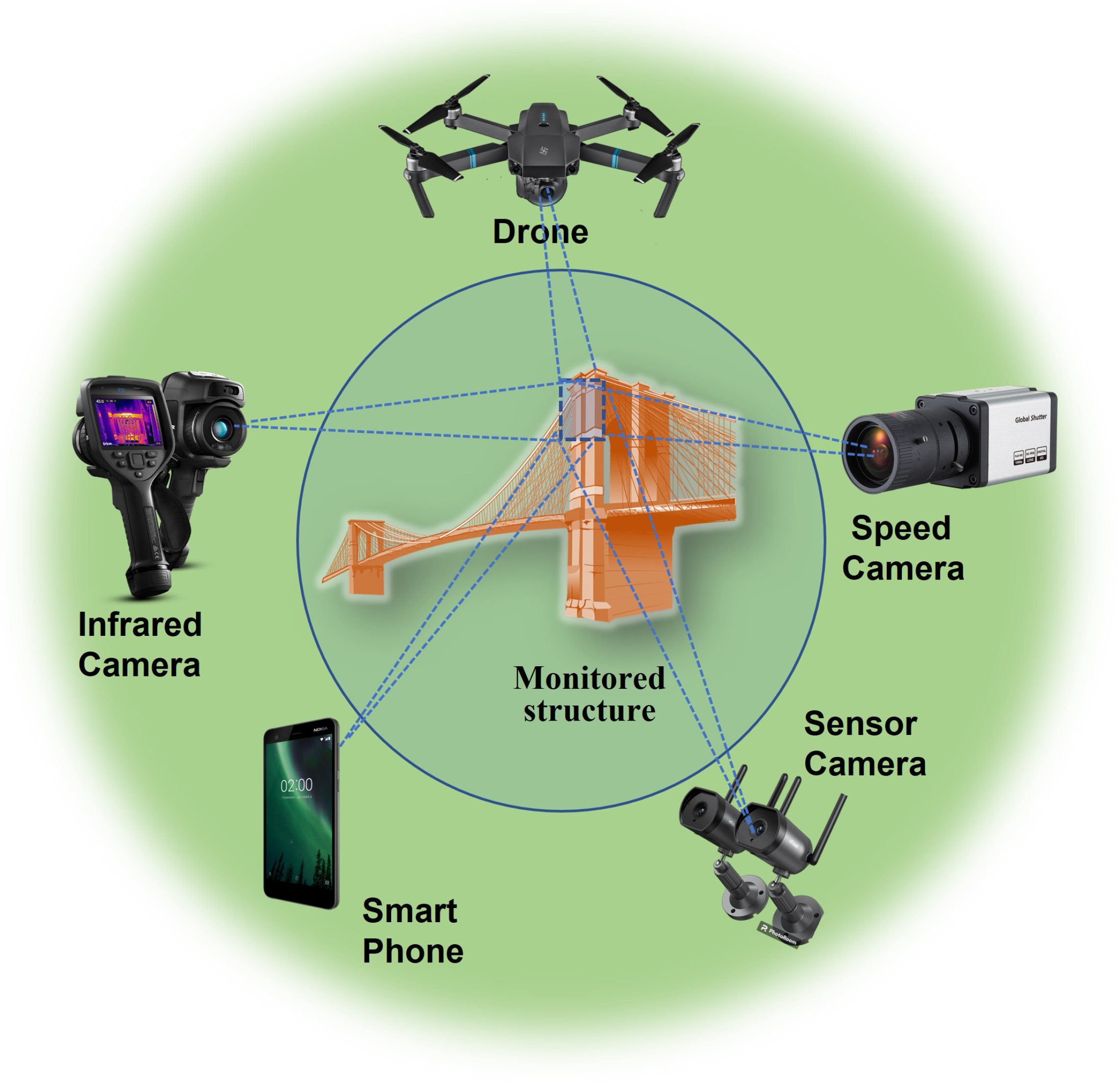
2.1. Image Acquisition
2.2. Image Preprocessing
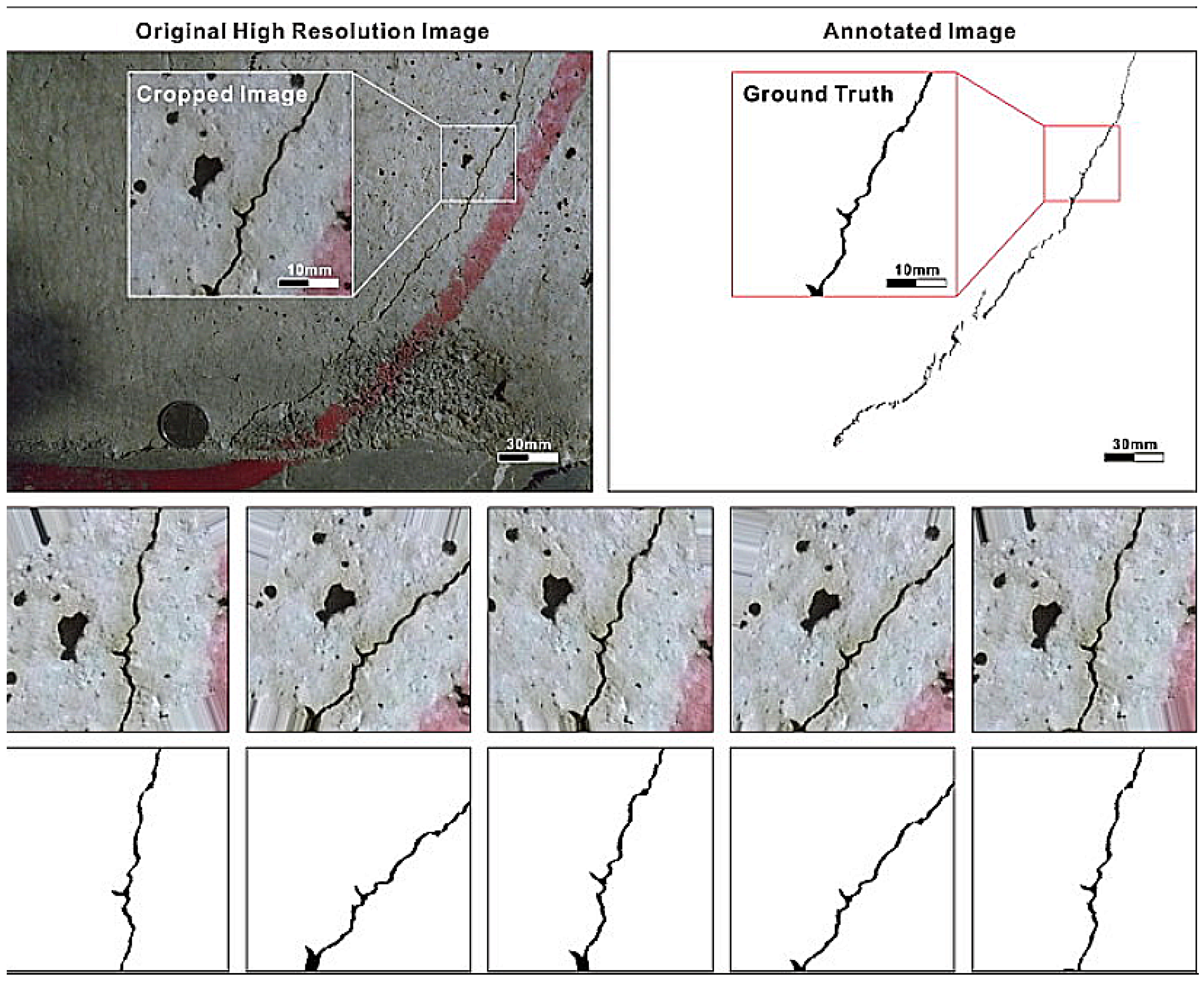
2.2.1. Image Cropping and Scaling
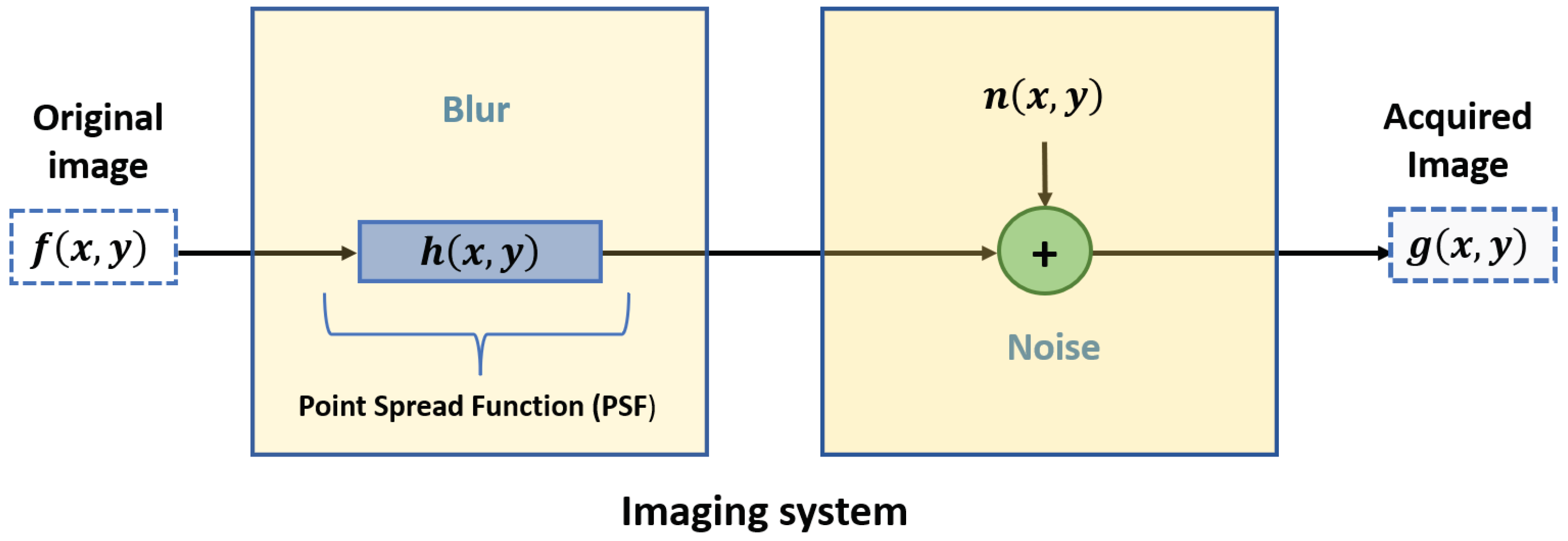
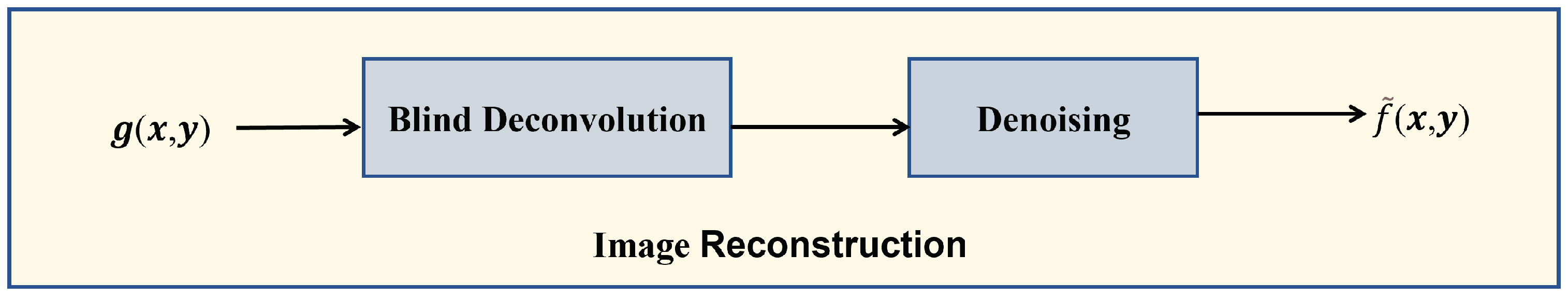
2.2.2. Noise and Blur Reduction
2.2.3. Image Enhancement
2.3. Edge Detection Methods for Crack Detection
2.3.1. Roberts Edge Detection
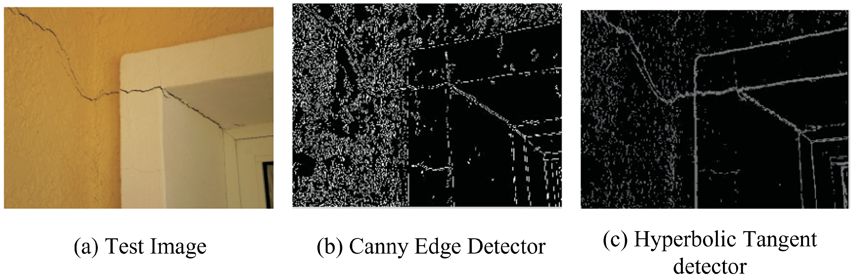
2.3.2. Canny Edge Detection
- Step 1:
- The image is convolved with a Gaussian function to generate a smooth image, , which is defined as follows:whereFurthermore, represents a Gaussian function characterized by the variance .
- Step 2:
- The first difference gradient operator is applied to compute the edge strength, and the edge magnitude and direction are obtained as before. The following matrices are Sobel operators and use a pair of 3 × 3 convolution masks (see Equations (8) and (9)).
- Step 3:
- The non-maximal or critical suppression is applied to the gradient magnitude.
- Step 4:
- A threshold is applied to the non-maximal suppression image.
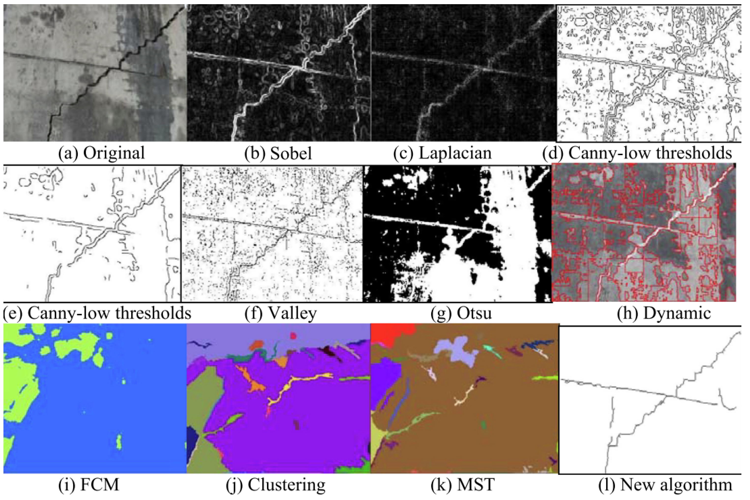
2.3.3. Sobel Edge Detection
2.3.4. Prewitt Edge Detection
2.3.5. Laplacian of Gaussian (LoG) Operator
2.4. Traditional Segmentation Methods
Thresholding-Based Segmentation
- (a)
- Global thresholding
- (b)
- Otsu thresholding
- (c)
- Adaptive thresholding Segmentation
- (d)
- Region-based Segmentation
2.5. Morphological Operations
2.6. Smartphone
2.7. Unmanned Aerial Vehicle (UAV)
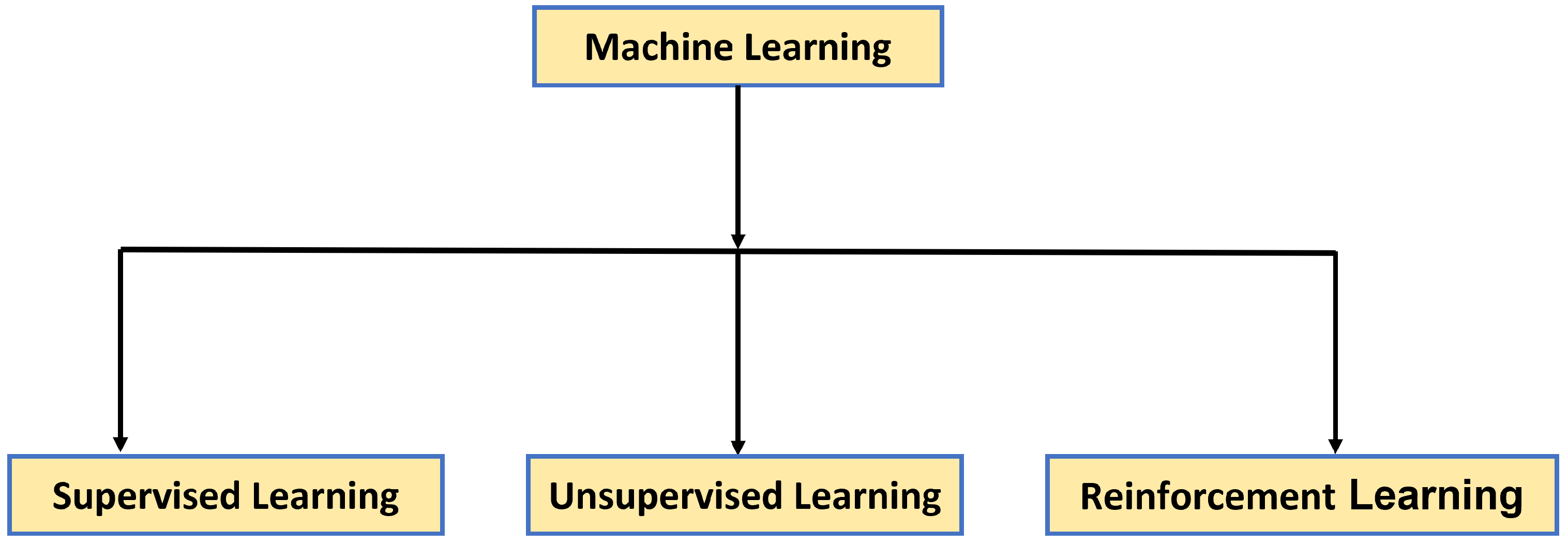
3. The Role of Machine Learning Algorithms Based on Vision for Crack Detection
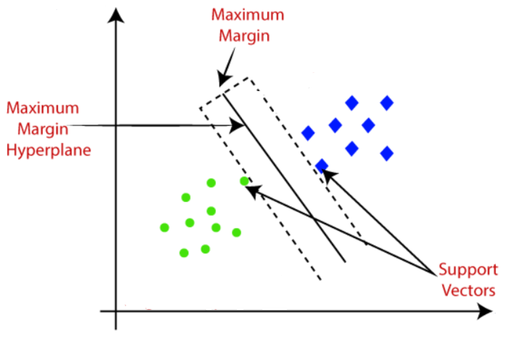
3.1. Support Vector Machine (SVM)
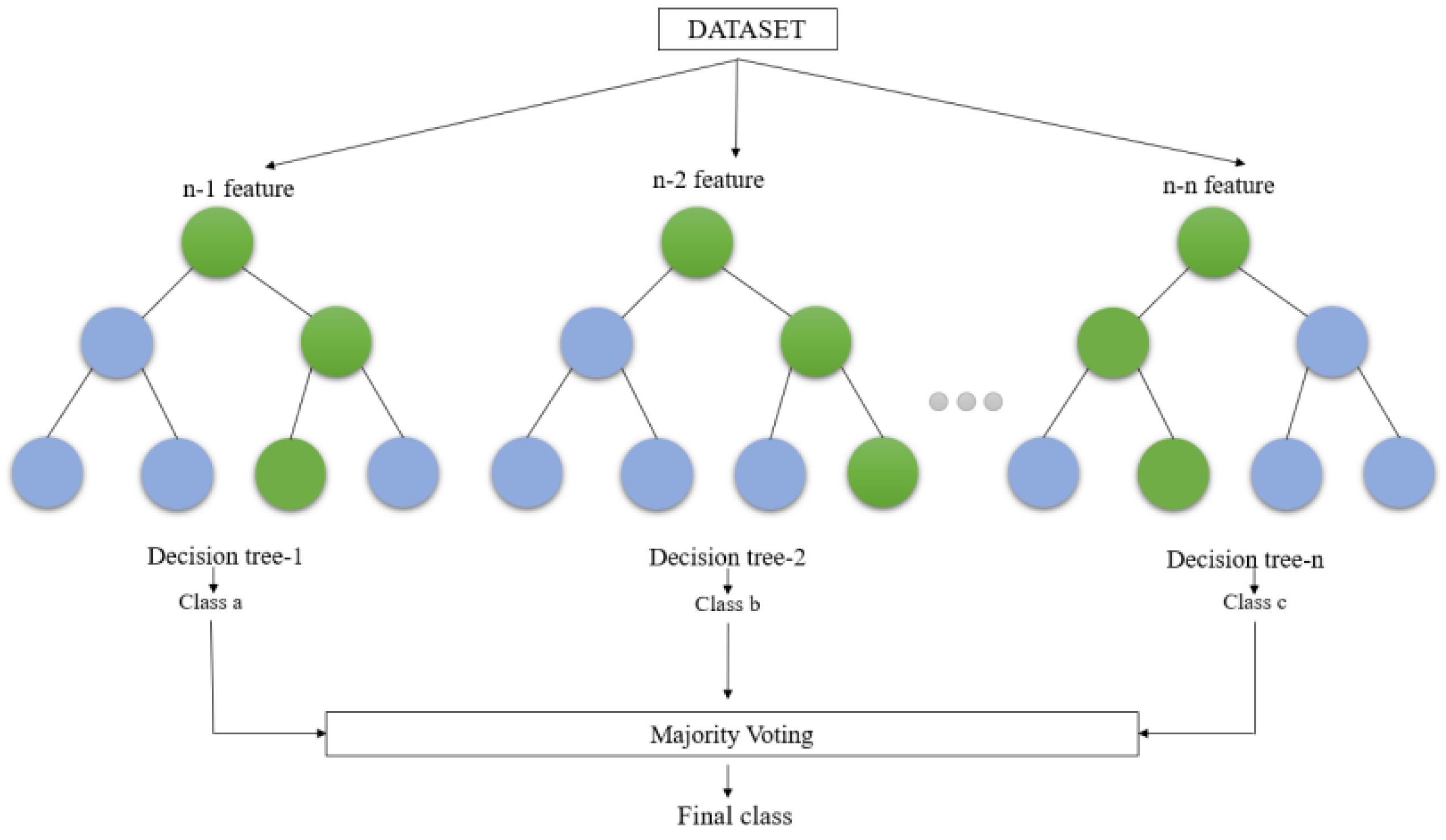
3.2. Decision Tree Algorithm
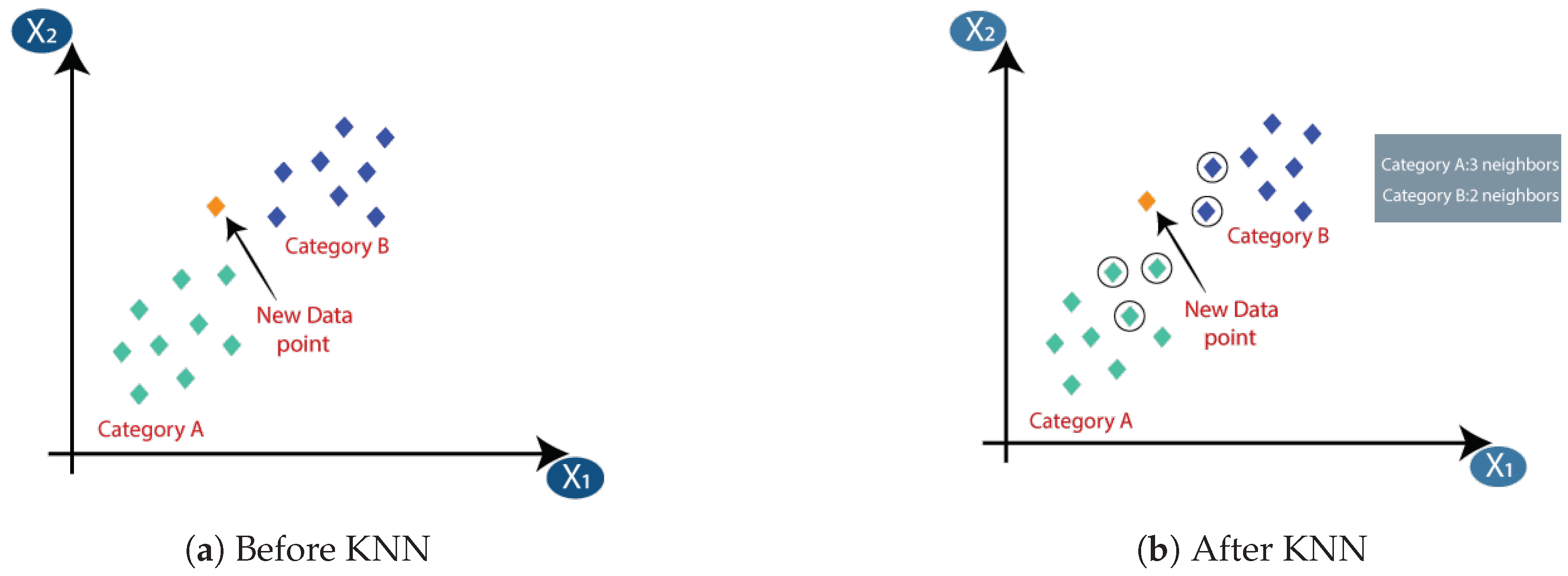
3.3. k-Nearest Neighbor Algorithm (KNN)
3.4. Random Structured Forests
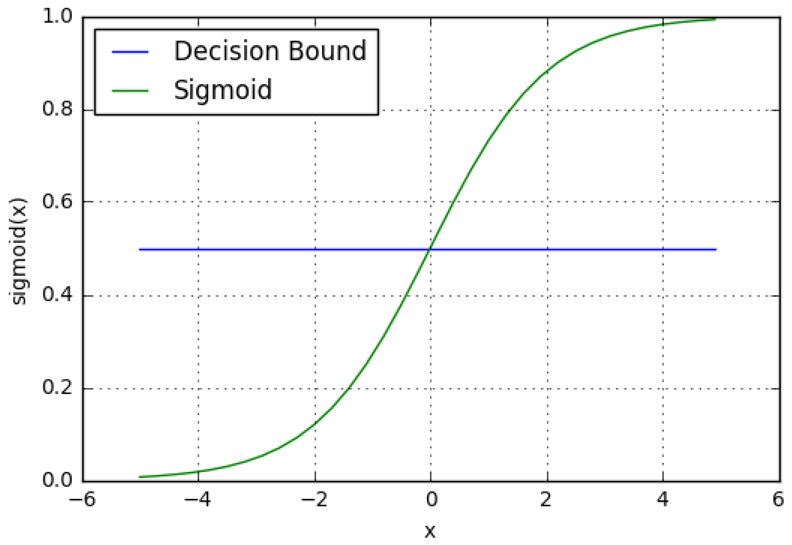
3.5. Logistic Regression
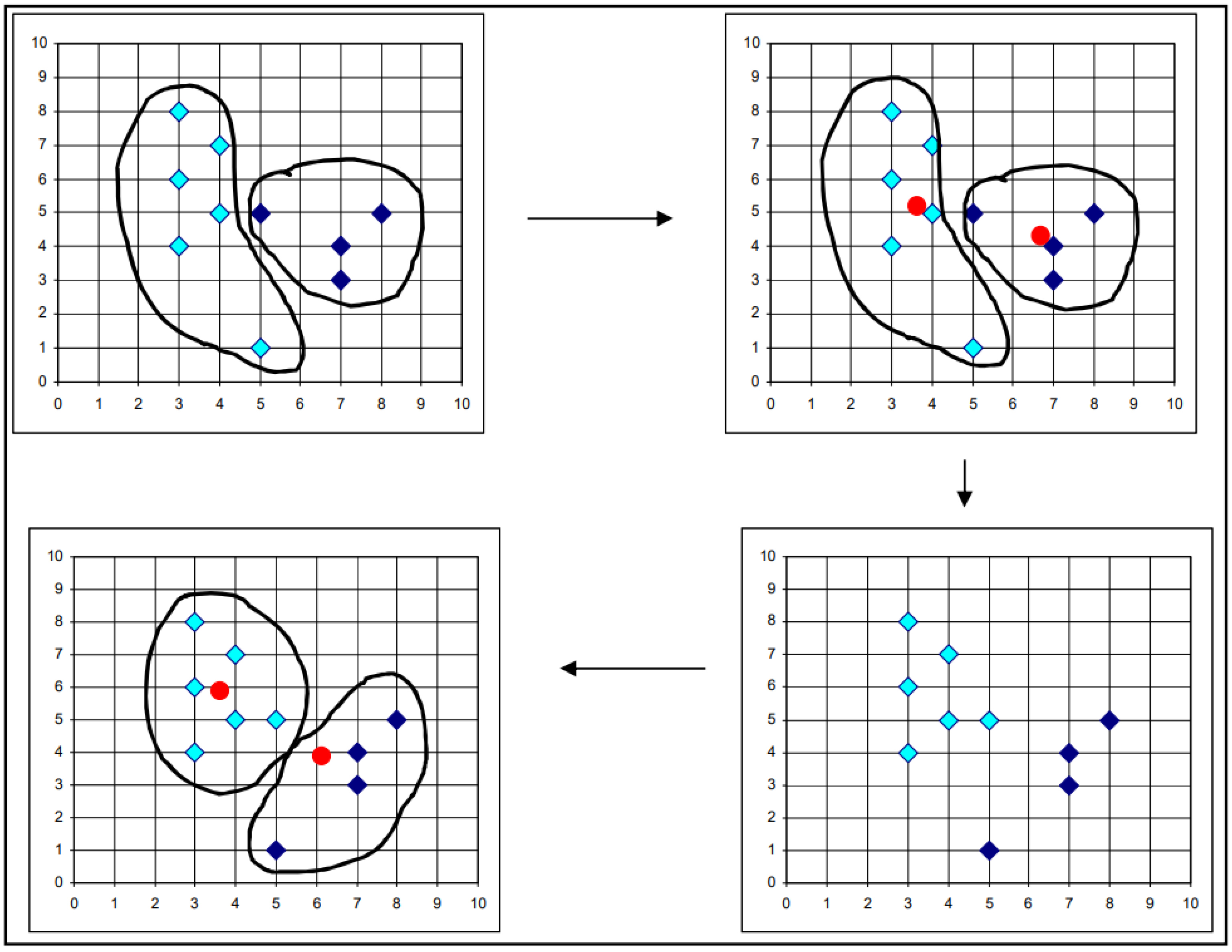
3.6. K-Means Clustering Algorithm
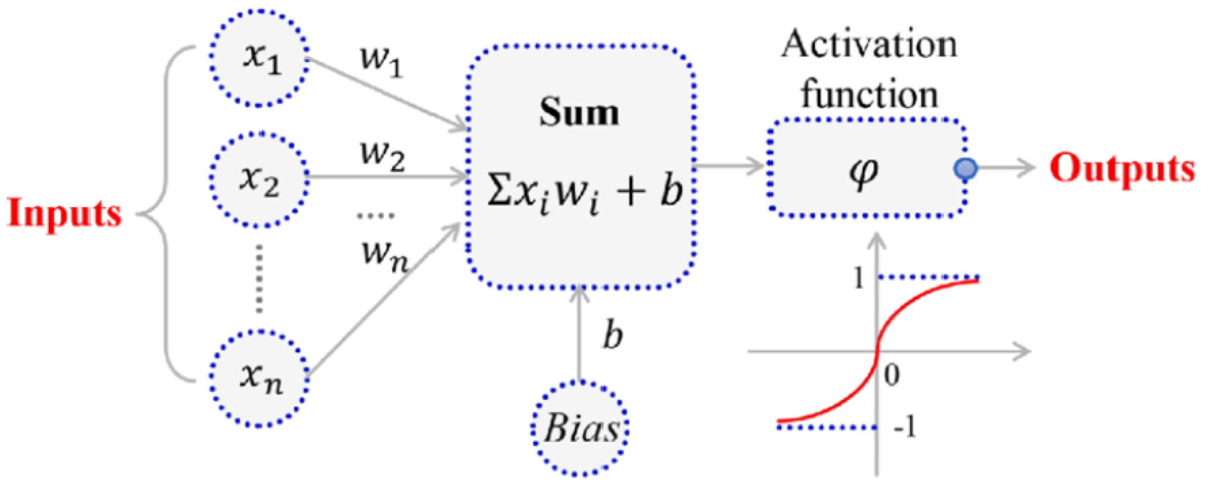
3.7. Artificial Neural Network
3.8. Deep Learning
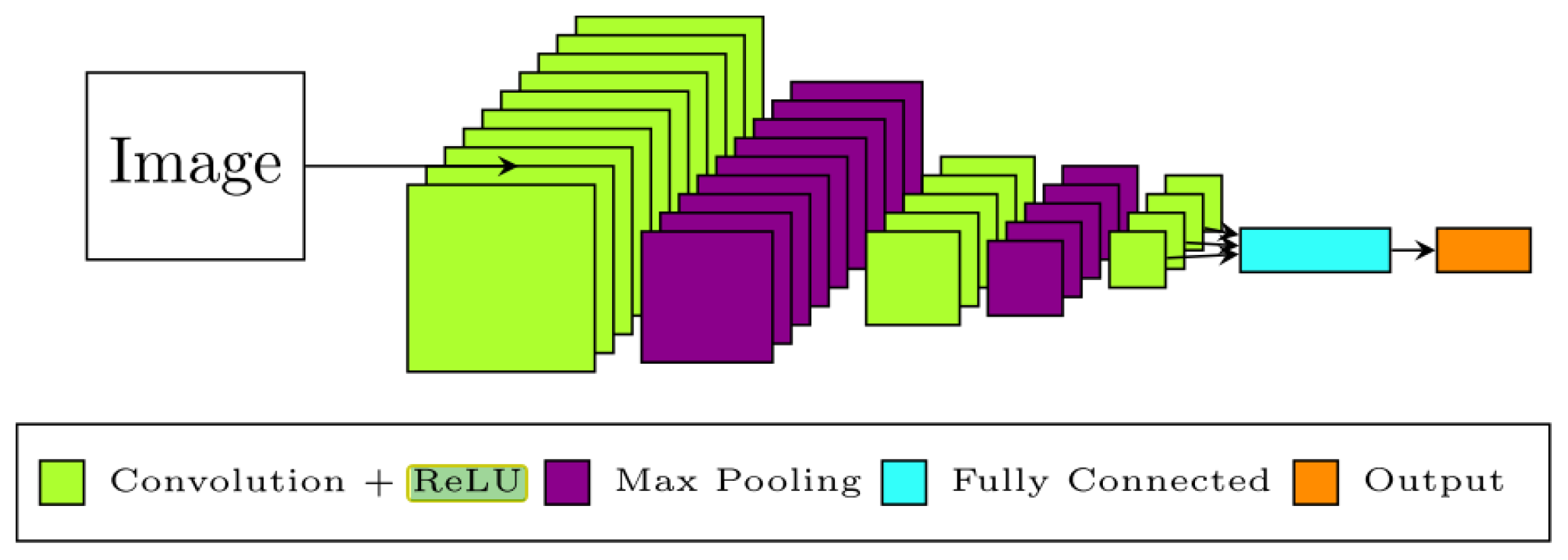
Convolutional Neural Networks (CNN)
4. Integration of Image Processing Techniques and Dynamic Response Measurements
4.1. Motion Magnification
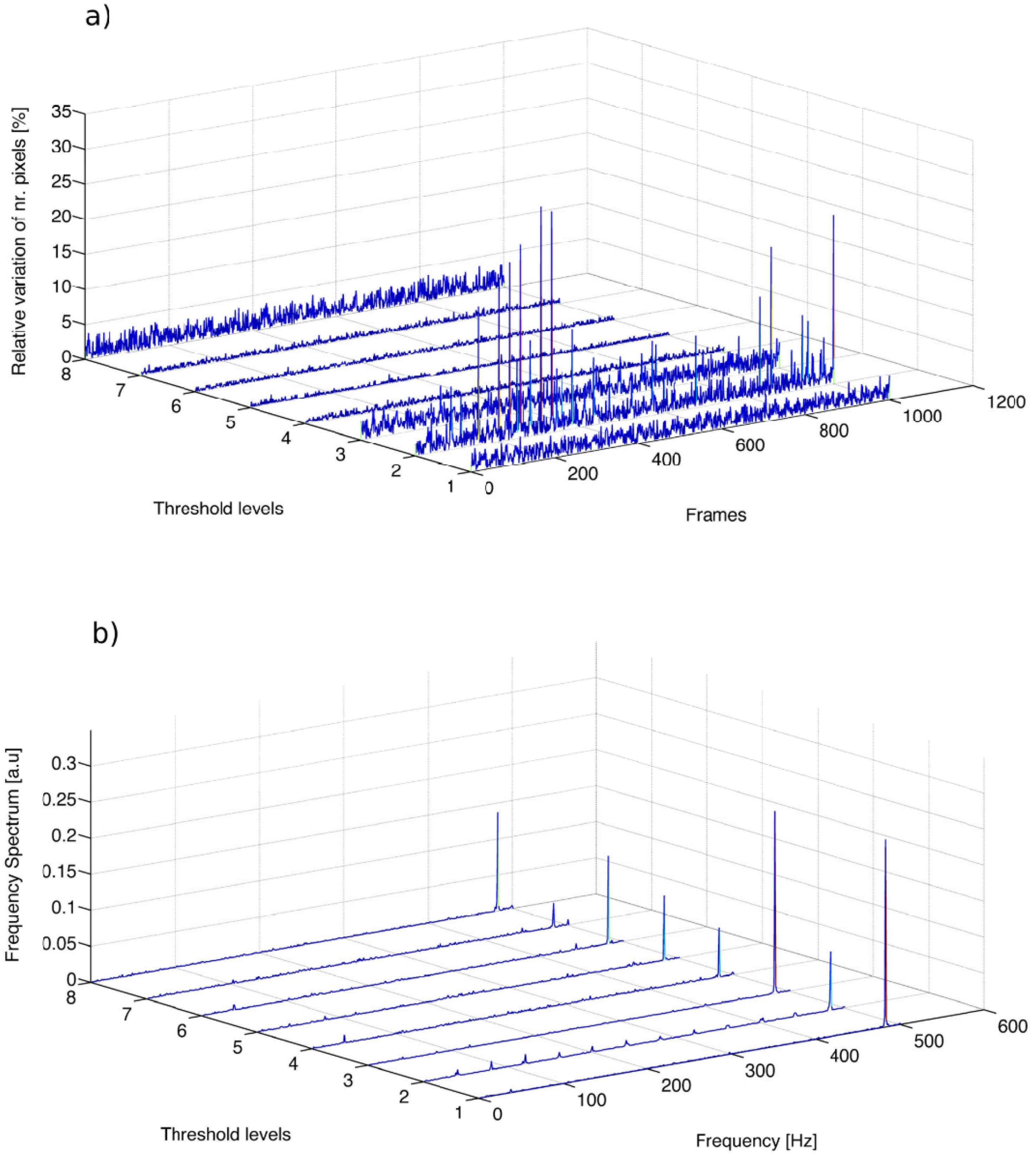
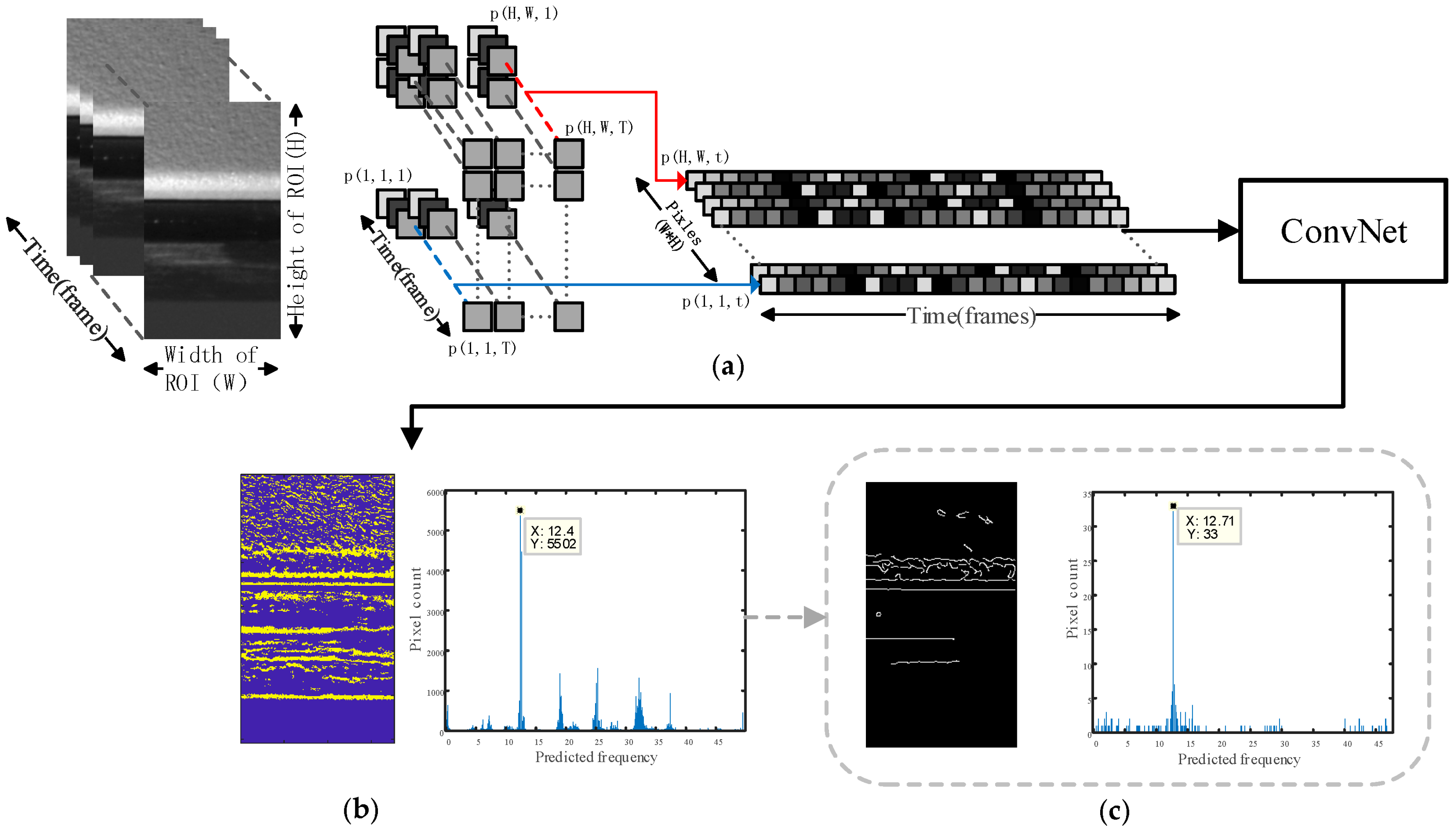
4.2. Multithresholding Technique
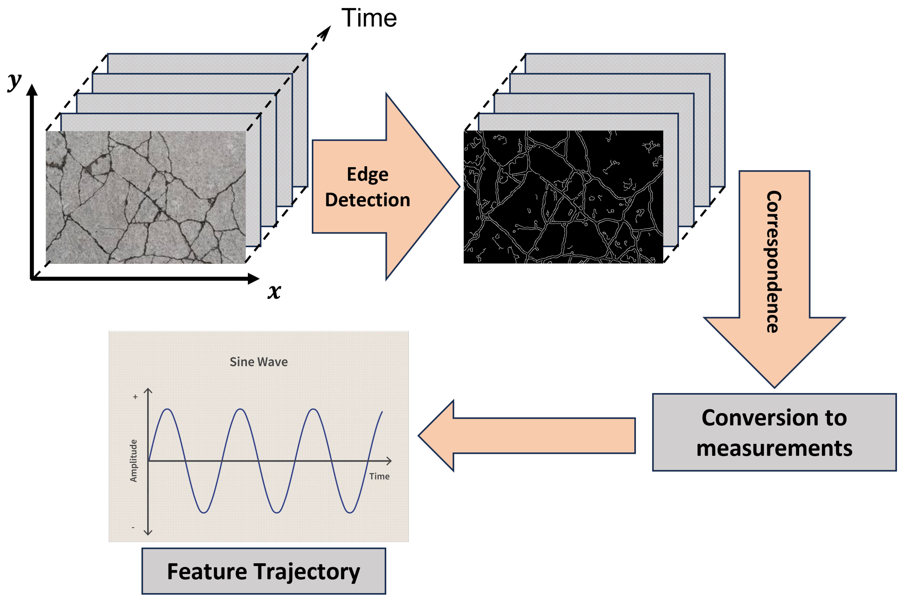
4.3. Edge Detection Techniques
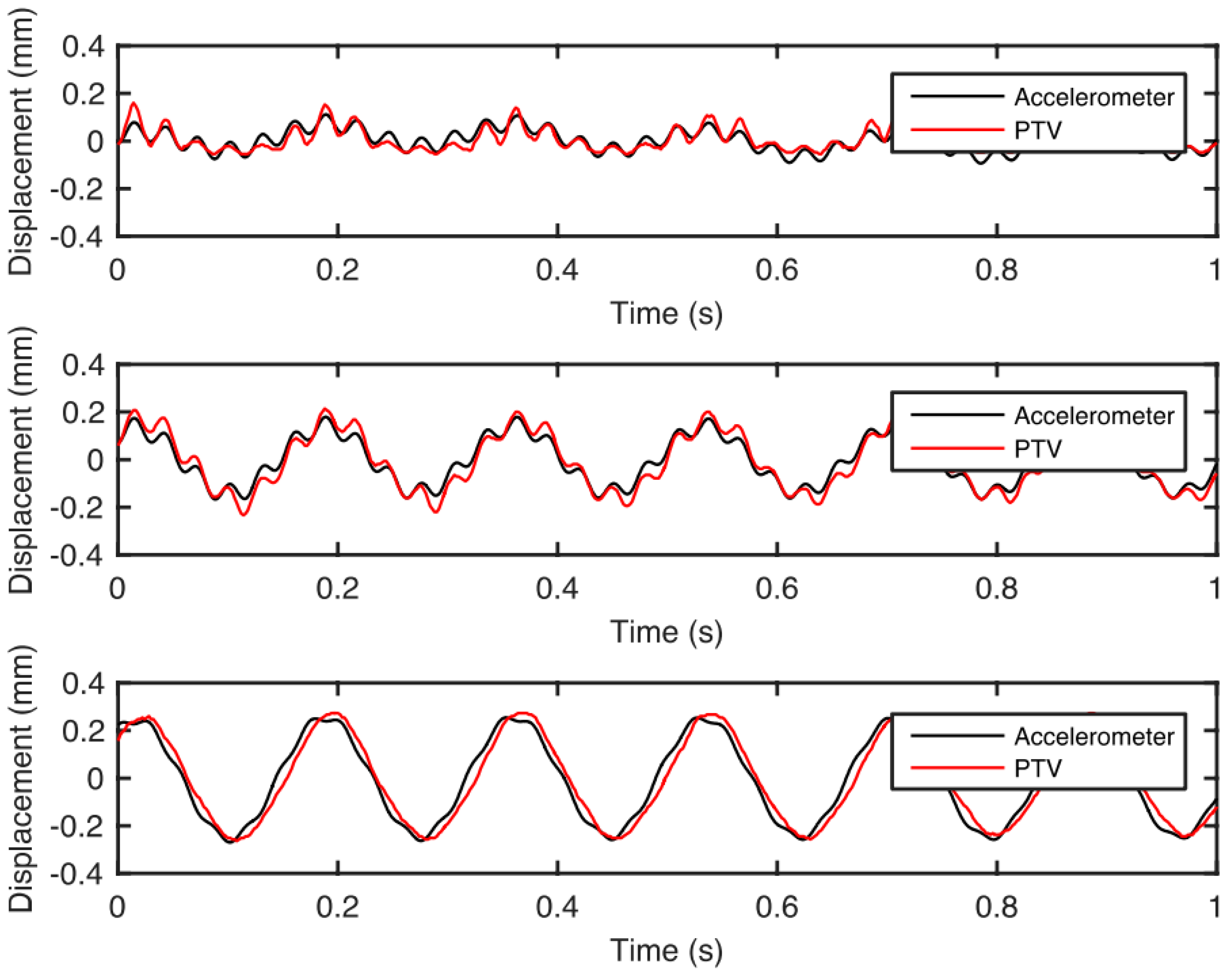
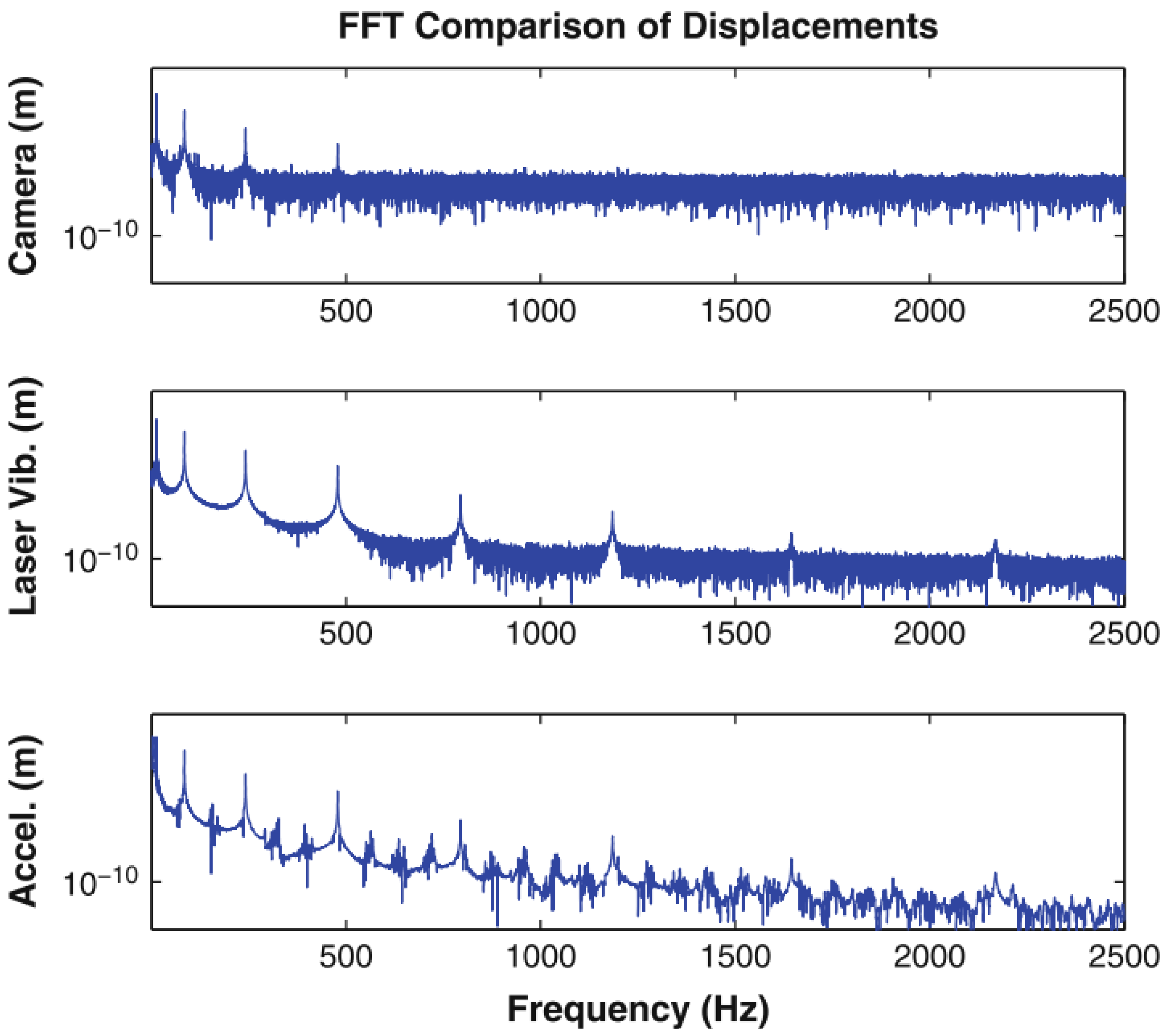
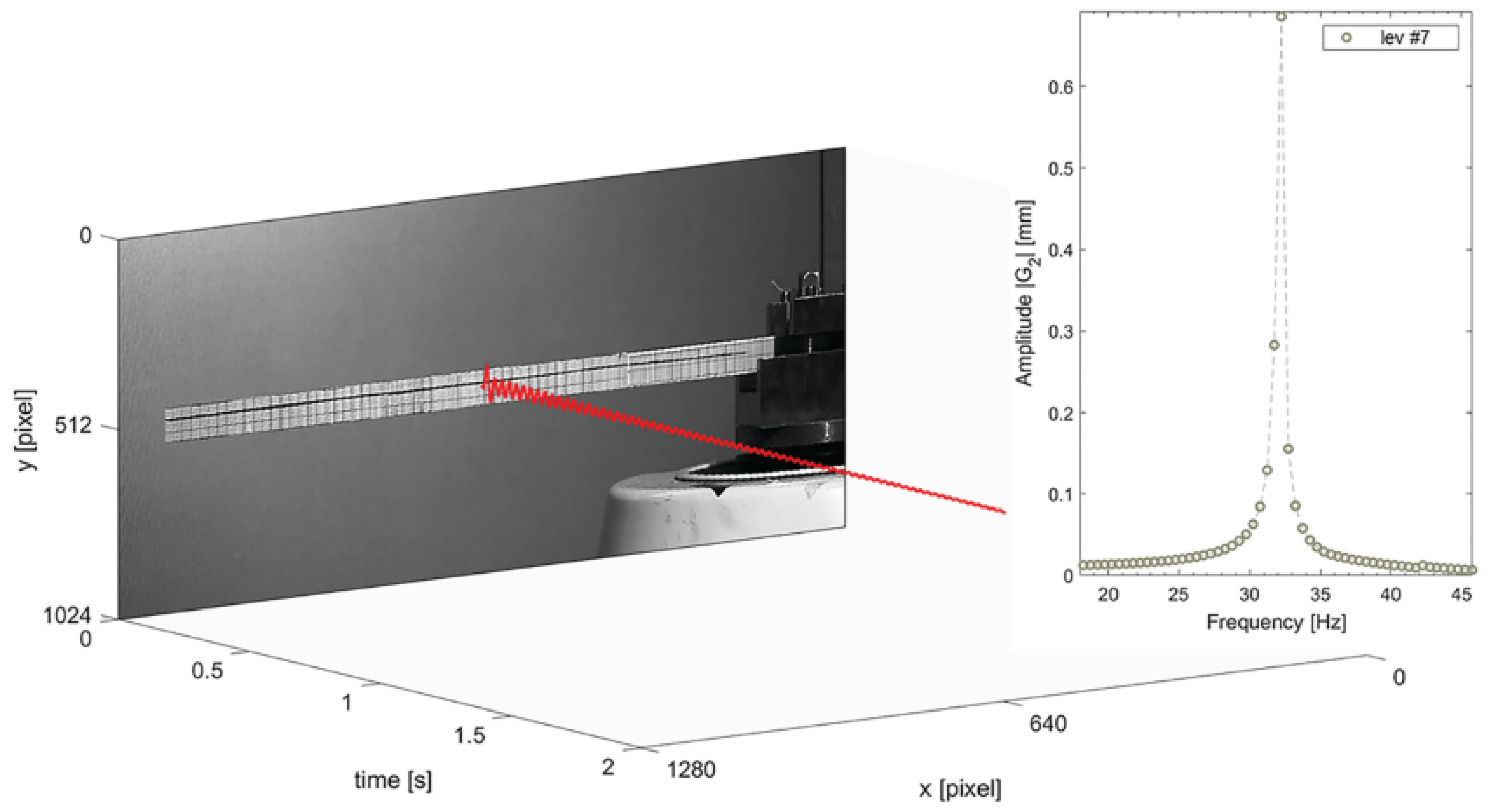
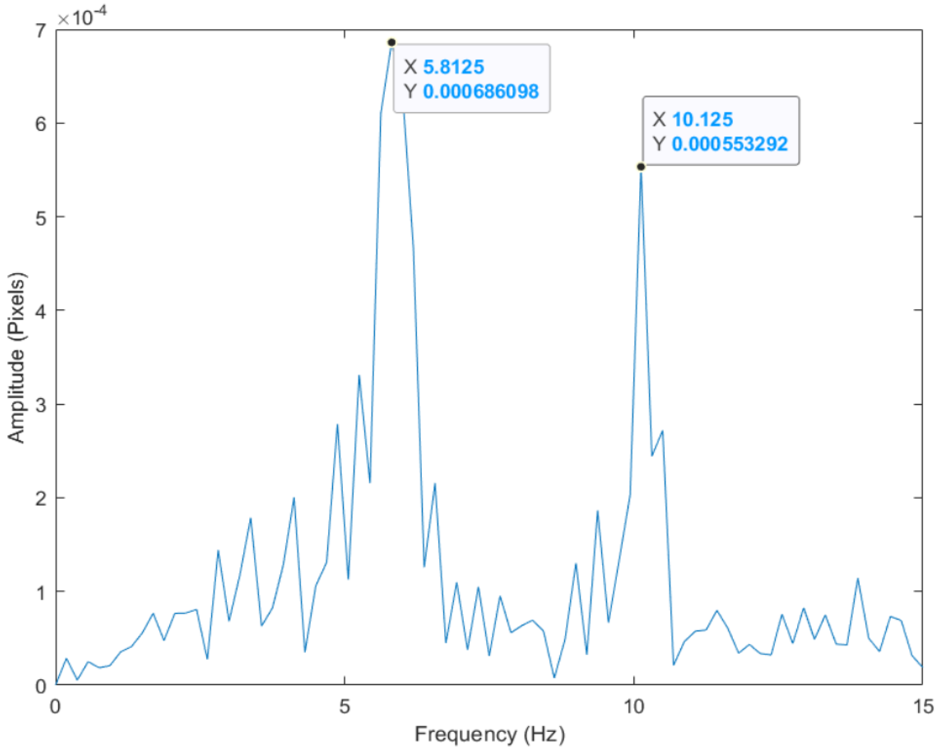
4.4. Target Tracking
5. Conclusions
Author Contributions
Funding
Institutional Review Board Statement
Informed Consent Statement
Data Availability Statement
Conflicts of Interest
References
- Yao, Y.; Tung, S.T.E.; Glisic, B. Crack detection and characterization techniques—An overview. Struct. Control Health Monit. 2014, 21, 1387–1413. [Google Scholar] [CrossRef]
- Dong, C.Z.; Catbas, F.N. A review of computer vision–based structural health monitoring at local and global levels. Struct. Health Monit. 2021, 20, 692–743. [Google Scholar] [CrossRef]
- Sony, S.; Laventure, S.; Sadhu, A. A literature review of next-generation smart sensing technology in structural health monitoring. Struct. Control Health Monit. 2019, 26, e2321. [Google Scholar] [CrossRef]
- Flah, M.; Suleiman, A.R.; Nehdi, M.L. Classification and quantification of cracks in concrete structures using deep learning image-based techniques. Cem. Concr. Compos. 2020, 114, 103781. [Google Scholar] [CrossRef]
- LeBlanc, B.; Niezrecki, C.; Avitabile, P.; Chen, J.; Sherwood, J. Damage detection and full surface characterization of a wind turbine blade using three-dimensional digital image correlation. Struct. Health Monit. 2013, 12, 430–439. [Google Scholar] [CrossRef]
- Li, J.; Xie, X.; Yang, G.; Zhang, B.; Siebert, T.; Yang, L. Whole-field thickness strain measurement using multiple camera digital image correlation system. Opt. Lasers Eng. 2017, 90, 19–25. [Google Scholar] [CrossRef]
- Dabous, S.A.; Feroz, S. Condition monitoring of bridges with non-contact testing technologies. Autom. Constr. 2020, 116, 103224. [Google Scholar] [CrossRef]
- Feng, D.; Feng, M.Q.; Ozer, E.; Fukuda, Y. A vision-based sensor for noncontact structural displacement measurement. Sensors 2015, 15, 16557–16575. [Google Scholar] [CrossRef]
- Kou, X.; Pei, C.; Chen, Z. Fully noncontact inspection of closed surface crack with nonlinear laser ultrasonic testing method. Ultrasonics 2021, 114, 106426. [Google Scholar] [CrossRef]
- Zhu, D.; Cheng, Q.; He, J.; Hong, W.; Liu, W.; Yang, S.; Wang, D. Differential two-wave mixing interferometer for crack detection in metallic structures based on laser-induced ultrasound. Opt. Lasers Eng. 2023, 164, 107485. [Google Scholar] [CrossRef]
- Kang, K.C.; Park, K.K. Noncontact laser ultrasound detection of cracks using hydrophone. Sensors 2021, 21, 3371. [Google Scholar] [CrossRef] [PubMed]
- Gao, F.; Zhou, H.; Huang, C. Defect detection using the phased-array laser ultrasonic crack diffraction enhancement method. Opt. Commun. 2020, 474, 126070. [Google Scholar] [CrossRef]
- Wen, T.K.; Yin, C.C. Crack detection in photovoltaic cells by interferometric analysis of electronic speckle patterns. Sol. Energy Mater. Sol. Cells 2012, 98, 216–223. [Google Scholar] [CrossRef]
- Kaczmarek, R.; Dupré, J.C.; Doumalin, P.; Pop, O.; Teixeira, L.; Huger, M. High-temperature digital image correlation techniques for full-field strain and crack length measurement on ceramics at 1200 °C: Optimization of speckle pattern and uncertainty assessment. Opt. Lasers Eng. 2021, 146, 106716. [Google Scholar] [CrossRef]
- Wang, T.; Wang, Y.; Yang, X.; Chen, B.; Zhu, H. Cracks and process control in laser powder bed fusion of Al-Zn-Mg alloy. J. Manuf. Process. 2022, 81, 571–579. [Google Scholar] [CrossRef]
- Wall, A.; Benoit, M.J. A Review of Existing Solidification Crack Tests and Analysis of Their Transferability to Additive Manufacturing. J. Mater. Process. Technol. 2023, 320, 118090. [Google Scholar] [CrossRef]
- Liu, T.; Ji, Z.; Ding, Y.; Zhu, Y. Real-Time Laser Interference Detection of Mechanical Targets Using a 4R Manipulator. Sensors 2023, 23, 2794. [Google Scholar] [CrossRef]
- Erkal, B.G.; Hajjar, J.F. Laser-based surface damage detection and quantification using predicted surface properties. Autom. Constr. 2017, 83, 285–302. [Google Scholar] [CrossRef]
- Liu, N.; Song, W.; Zhao, Q. Morphology and maximum entropy image segmentation based urban pavement cracks detection. J. Liaoning Tech. Univ. Nat. Sci. Ed. 2015, 34, 57–61. [Google Scholar]
- Othman, Z.; Abdullah, A.; Kasmin, F.; Ahmad, S.S.S. Road crack detection using adaptive multi resolution thresholding techniques. TELKOMNIKA Telecommun. Comput. Electron. Control. 2019, 17, 1874–1881. [Google Scholar] [CrossRef]
- Song, C.; Wu, L.; Chen, Z.; Zhou, H.; Wu, Z. Pixel-Level Crack Detection in Images Using SegNet. In Multi-Disciplinary Trends in Artificial Intelligence Proceedings of the 13th International Conference, MIWAI 2019, Kuala Lumpur, Malaysia, 17–19 November 2019; Springer: Berlin, Germany, 2019. [Google Scholar]
- Prabakar, C.V.; Nagarajan, C.K. A novel approach of surface crack detection using super pixel segmentation. Mater. Today Proc. 2021, 42, 1043–1049. [Google Scholar] [CrossRef]
- Harjit, K.; Rajandeep, K. A Review on Crack Detection and Parameters Estimation on Road Images. Int. J. Res. Appl. Sci. Eng. Technol. 2017, 5, 1–4. [Google Scholar]
- Parente, L.; Castagnetti, C.; Falvo, E.; Rossi, P.; Grassi, F.; Mancini, F.; Capra, A. Towards an automated machine learning and image processing supported procedure for crack monitoring. In Proceedings of the 5th Joint International Symposium on Deformation Monitoring (JISDM 2022)—Editorial Universitat Politècnica de València, València, Spain, 20–22 June 2023; pp. 237–242. [Google Scholar]
- Hsieh, Y.A.; Tsai, Y.J. Machine learning for crack detection: Review and model performance comparison. J. Comput. Civ. Eng. 2020, 34, 04020038. [Google Scholar] [CrossRef]
- Peng, J.; Zhang, S.; Peng, D.; Liang, K. Research on bridge crack detection with neural network based image processing methods. In Proceedings of the 2018 12th International Conference on Reliability, Maintainability, and Safety (ICRMS), Shanghai, China, 17–19 October 2018; pp. 419–428. [Google Scholar]
- Hoang, N.D. Image processing-based recognition of wall defects using machine learning approaches and steerable filters. Comput. Intell. Neurosci. 2018, 2018, 7913952. [Google Scholar] [CrossRef]
- Munawar, H.S.; Hammad, A.W.; Haddad, A.; Soares, C.A.P.; Waller, S.T. Image-based crack detection methods: A review. Infrastructures 2021, 6, 115. [Google Scholar] [CrossRef]
- Kim, C.N.; Kawamura, K.; Nakamura, H.; Tarighat, A. Automatic crack detection for concrete infrastructures using image processing and deep learning. In Proceedings of the IOP Conference Series: Materials Science and Engineering, Tokyo, Japan, 26–29 February 2020; IOP Publishing: Bristol, UK, 2020; Volume 829, p. 012027. [Google Scholar]
- Miao, Y.; Jeon, J.Y.; Park, G. An image processing-based crack detection technique for pressed panel products. J. Manuf. Syst. 2020, 57, 287–297. [Google Scholar] [CrossRef]
- Shariati, A.; Schumacher, T.; Ramanna, N. Exploration of Video-Based Structural Health Monitoring Techniques; Technical Report; Rutgers University, Center for Advanced Infrastructure & Transportation: New Brunswick, NJ, USA, 2014. [Google Scholar]
- Zimmermann, M.; Gülan, U.; Harmanci, Y.E.; Chatzi, E.N.; Holzner, M. Structural health monitoring through video recording. In Proceedings of the 8th European Workshop on Structural Health Monitoring (EWSHM 2016), Bilbao, Spain, 5–8 July 2016; pp. 5–8. [Google Scholar]
- Schumacher, T.; Shariati, A. Monitoring of structures and mechanical systems using virtual visual sensors for video analysis: Fundamental concept and proof of feasibility. Sensors 2013, 13, 16551–16564. [Google Scholar] [CrossRef]
- Taghavi Larigani, S.; Heaton, T.H. Characterizing Deformation of Buildings from Videos; California Institute of Technology: Pasadena, CA, USA, 2016. [Google Scholar]
- Medhi, M.; Dandautiya, A.; Raheja, J.L. Real-time video surveillance based structural health monitoring of civil structures using artificial neural network. J. Nondestruct. Eval. 2019, 38, 1–16. [Google Scholar] [CrossRef]
- Dworakowski, Z.; Kohut, P.; Gallina, A.; Holak, K.; Uhl, T. Vision-based algorithms for damage detection and localization in structural health monitoring. Struct. Control Health Monit. 2016, 23, 35–50. [Google Scholar] [CrossRef]
- Fukuda, Y.; Feng, M.Q.; Narita, Y.; Kaneko, S.; Tanaka, T. Vision-based displacement sensor for monitoring dynamic response using robust object search algorithm. IEEE Sens. J. 2013, 13, 4725–4732. [Google Scholar] [CrossRef]
- Xu, Y.; Brownjohn, J.M. Review of machine-vision based methodologies for displacement measurement in civil structures. J. Civ. Struct. Health Monit. 2018, 8, 91–110. [Google Scholar] [CrossRef]
- Scholar, P. Review and analysis of crack detection and classification techniques based on crack types. Int. J. Appl. Eng. Res 2018, 13, 6056–6062. [Google Scholar]
- Mohan, A.; Poobal, S. Crack detection using image processing: A critical review and analysis. Alex. Eng. J. 2018, 57, 787–798. [Google Scholar] [CrossRef]
- Ali, R.; Gopal, D.L.; Cha, Y.J. Vision-based concrete crack detection technique using cascade features. In Proceedings of the Sensors and Smart Structures Technologies for Civil, Mechanical, and Aerospace Systems, Denver, CO, USA, 5–8 March 2018; Volume 10598, pp. 147–153. [Google Scholar]
- Dorafshan, S.; Thomas, R.J.; Maguire, M. Benchmarking image processing algorithms for unmanned aerial system-assisted crack detection in concrete structures. Infrastructures 2019, 4, 19. [Google Scholar] [CrossRef]
- Han, H.; Deng, H.; Dong, Q.; Gu, X.; Zhang, T.; Wang, Y. An advanced Otsu method integrated with edge detection and decision tree for crack detection in highway transportation infrastructure. Adv. Mater. Sci. Eng. 2021, 2021, 9205509. [Google Scholar] [CrossRef]
- Wang, P.; Huang, H. Comparison analysis on present image-based crack detection methods in concrete structures. In Proceedings of the 2010 3rd International Congress on Image and Signal Processing, Yantai, China, 16–18 October 2010; Volume 5, pp. 2530–2533. [Google Scholar]
- Liu, X.; Ai, Y.; Scherer, S. Robust image-based crack detection in concrete structure using multi-scale enhancement and visual features. In Proceedings of the 2017 IEEE International Conference on Image Processing (ICIP), Beijing, China, 17–20 September 2017; pp. 2304–2308. [Google Scholar]
- Daneshgaran, F.; Zacheo, L.; Stasio, F.D.; Mondin, M. Use of deep learning for automatic detection of cracks in tunnels: Prototype-2 developed in the 2017–2018 time period. Transp. Res. Rec. 2019, 2673, 44–50. [Google Scholar] [CrossRef]
- Perez, H.; Tah, J.H.; Mosavi, A. Deep learning for detecting building defects using convolutional neural networks. Sensors 2019, 19, 3556. [Google Scholar] [CrossRef]
- Zhang, L.; Shen, J.; Zhu, B. A research on an improved Unet-based concrete crack detection algorithm. Struct. Health Monit. 2021, 20, 1864–1879. [Google Scholar] [CrossRef]
- Ye, X.W.; Jin, T.; Chen, P.Y. Structural crack detection using deep learning–based fully convolutional networks. Adv. Struct. Eng. 2019, 22, 3412–3419. [Google Scholar] [CrossRef]
- Han, Y.; Liu, Z.; Lyu, Y.; Liu, K.; Li, C.; Zhang, W. Deep learning-based visual ensemble method for high-speed railway catenary clevis fracture detection. Neurocomputing 2020, 396, 556–568. [Google Scholar] [CrossRef]
- Ren, Y.; Huang, J.; Hong, Z.; Lu, W.; Yin, J.; Zou, L.; Shen, X. Image-based concrete crack detection in tunnels using deep fully convolutional networks. Constr. Build. Mater. 2020, 234, 117367. [Google Scholar] [CrossRef]
- Hoang, N.D.; Nguyen, Q.L. Metaheuristic optimized edge detection for recognition of concrete wall cracks: A comparative study on the performances of roberts, prewitt, canny, and sobel algorithms. Adv. Civ. Eng. 2018, 2018, 1–16. [Google Scholar] [CrossRef]
- Stentoumis, C.; Protopapadakis, E.; Doulamis, A.; Doulamis, N. A holistic approach for inspection of civil infrastructures based on computer vision techniques. Int. Arch. Photogramm. Remote Sens. Spat. Inf. Sci. 2016, 41, 131–138. [Google Scholar] [CrossRef]
- Chen, J.G.; Davis, A.; Wadhwa, N.; Durand, F.; Freeman, W.T.; Büyüköztürk, O. Video camera–based vibration measurement for civil infrastructure applications. J. Infrastruct. Syst. 2017, 23, B4016013. [Google Scholar] [CrossRef]
- Ni, T.; Zhou, R.; Gu, C.; Yang, Y. Measurement of concrete crack feature with android smartphone APP based on digital image processing techniques. Measurement 2020, 150, 107093. [Google Scholar] [CrossRef]
- Kang, S.M.; Chun, C.J.; Shim, S.B.; Ryu, S.K.; Baek, J.D. Real Time Image Processing System for Detecting Infrastructure Damage: Crack. In Proceedings of the 2019 IEEE International Conference on Consumer Electronics (ICCE), Las Vegas, NV, USA, 11–13 January 2019; pp. 1–3. [Google Scholar]
- Otero, L.D.; Moyou, M.; Peter, A.; Otero, C.E. Towards a Remote Sensing System for Railroad Bridge Inspections: A Concrete Crack Detection Component. In Proceedings of the SoutheastCon 2018, St. Petersburg, FL, USA, 19–22 April 2018; pp. 1–4. [Google Scholar]
- Vijayan, V.; Joy, C.M.; Shailesh, S. A Survey on Surface Crack Detection in Concretes using Traditional, Image Processing, Machine Learning, and Deep Learning Techniques. In Proceedings of the 2021 International Conference on Communication, Control and Information Sciences (ICCISc), Idukki, India, 16–18 June 2021; Volume 1, pp. 1–6. [Google Scholar]
- Talab, A.M.A.; Huang, Z.; Xi, F.; HaiMing, L. Detection crack in image using Otsu method and multiple filtering in image processing techniques. Optik 2016, 127, 1030–1033. [Google Scholar] [CrossRef]
- Sankarasrinivasan, S.; Balasubramanian, E.; Karthik, K.; Chandrasekar, U.; Gupta, R. Health monitoring of civil structures with integrated UAV and image processing system. Procedia Comput. Sci. 2015, 54, 508–515. [Google Scholar] [CrossRef]
- Cho, O.H.; Kim, J.C.; Kim, E.K. Context-aware high-rise structure cracks image monitoring system using unmanned aerial vehicles. Int. J. Control Autom. 2016, 9, 11–18. [Google Scholar] [CrossRef]
- Hoang, N.D. Detection of surface crack in building structures using image processing technique with an improved Otsu method for image thresholding. Adv. Civ. Eng. 2018, 2018, 3924120. [Google Scholar] [CrossRef]
- Peng, T.; Kavya, T.S.; Jang, Y.M.; Kim, B.W. Concrete Crack Detection using Relative Standard Deviation for Image Thresholding. Int. J. Eng. Res. Technol. 2020, 13, 2720. [Google Scholar] [CrossRef]
- Hussain, Z.; Agarwal, D. A comparative analysis of edge detection techniques used in flame image processing. Int. J. Adv. Res. Sci. Eng. IJARSE 2015, 4, 3703–3711. [Google Scholar]
- Sia, J.S.Y.; Tan, T.S.; Yahya, A.B.; Tiong, M.F.T.; Sia, J.Y.X. Mini Kirsch Edge Detection and Its Sharpening Effect. Indones. J. Electr. Eng. Inform. IJEEI 2021, 9, 228–244. [Google Scholar]
- Öztürk, Ş.; Akdemir, B. Comparison of edge detection algorithms for texture analysis on glass production. Procedia-Soc. Behav. Sci. 2015, 195, 2675–2682. [Google Scholar] [CrossRef]
- Al-Amri, S.S.; Kalyankar, N.; Khamitkar, S. Image segmentation by using edge detection. Int. J. Comput. Sci. Eng. 2010, 2, 804–807. [Google Scholar]
- Pereira, F.C.; Pereira, C.E. Embedded image processing systems for automatic recognition of cracks using UAVs. IFAC PapersOnLine 2015, 48, 16–21. [Google Scholar] [CrossRef]
- Syahrian, N.M.; Risma, P.; Dewi, T. Vision-based pipe monitoring robot for crack detection using canny edge detection method as an image processing technique. Kinet. Game Technol. Inf. Syst. Comput. Netw. Comput. Electron. Control. 2017, 2, 243–250. [Google Scholar] [CrossRef]
- He, M.; Li, J.; Zhang, Y.; Li, W. Research on crack visualization method for dynamic detection of eddy current thermography. NDT E Int. 2020, 116, 102361. [Google Scholar] [CrossRef]
- Wang, W.; Li, L.; Han, Y. Crack detection in shadowed images on gray level deviations in a moving window and distance deviations between connected components. Constr. Build. Mater. 2021, 271, 121885. [Google Scholar] [CrossRef]
- Wang, Y.; Zhang, J.Y.; Liu, J.X.; Zhang, Y.; Chen, Z.P.; Li, C.G.; He, K.; Yan, R.B. Research on crack detection algorithm of the concrete bridge based on image processing. Procedia Comput. Sci. 2019, 154, 610–616. [Google Scholar] [CrossRef]
- Shrivakshan, G.; Chandrasekar, C. A comparison of various edge detection techniques used in image processing. Int. J. Comput. Sci. Issues IJCSI 2012, 9, 269. [Google Scholar]
- Lee, C.; Zhang, A.; Yu, B.; Park, S. Comparison study between RMS and edge detection image processing algorithms for a pulsed laser UWPI (Ultrasonic wave propagation imaging)-based NDT technique. Sensors 2017, 17, 1224. [Google Scholar] [CrossRef] [PubMed]
- Lim, R.S.; La, H.M.; Sheng, W. A robotic crack inspection and mapping system for bridge deck maintenance. IEEE Trans. Autom. Sci. Eng. 2014, 11, 367–378. [Google Scholar] [CrossRef]
- Lim, R.S.; La, H.M.; Shan, Z.; Sheng, W. Developing a crack inspection robot for bridge maintenance. In Proceedings of the 2011 IEEE International Conference on Robotics and Automation, Shanghai, China, 9–13 May 2011; pp. 6288–6293. [Google Scholar]
- Shen, G. Road crack detection based on video image processing. In Proceedings of the 2016 3rd International Conference on Systems and Informatics (ICSAI), Shanghai, China, 19–21 November 2016; pp. 912–917. [Google Scholar]
- Peng, L.; Chao, W.; Shuangmiao, L.; Baocai, F. Research on crack detection method of airport runway based on twice-threshold segmentation. In Proceedings of the 2015 Fifth International Conference on Instrumentation and Measurement, Computer, Communication and Control (IMCCC), Qinhuangdao, China, 18–20 September 2015; pp. 1716–1720. [Google Scholar]
- Senthikumar, M.; Palanisamy, V.; Jaya, J. Metal surface defect detection using iterative thresholding technique. In Proceedings of the Second International Conference on Current Trends in Engineering and Technology-ICCTET 2014, Coimbatore, India, 8 July 2014; pp. 561–564. [Google Scholar]
- Fan, R.; Bocus, M.J.; Zhu, Y.; Jiao, J.; Wang, L.; Ma, F.; Cheng, S.; Liu, M. Road crack detection using deep convolutional neural network and adaptive thresholding. In Proceedings of the 2019 IEEE Intelligent Vehicles Symposium (IV), Paris, France, 9–12 June 2019; pp. 474–479. [Google Scholar]
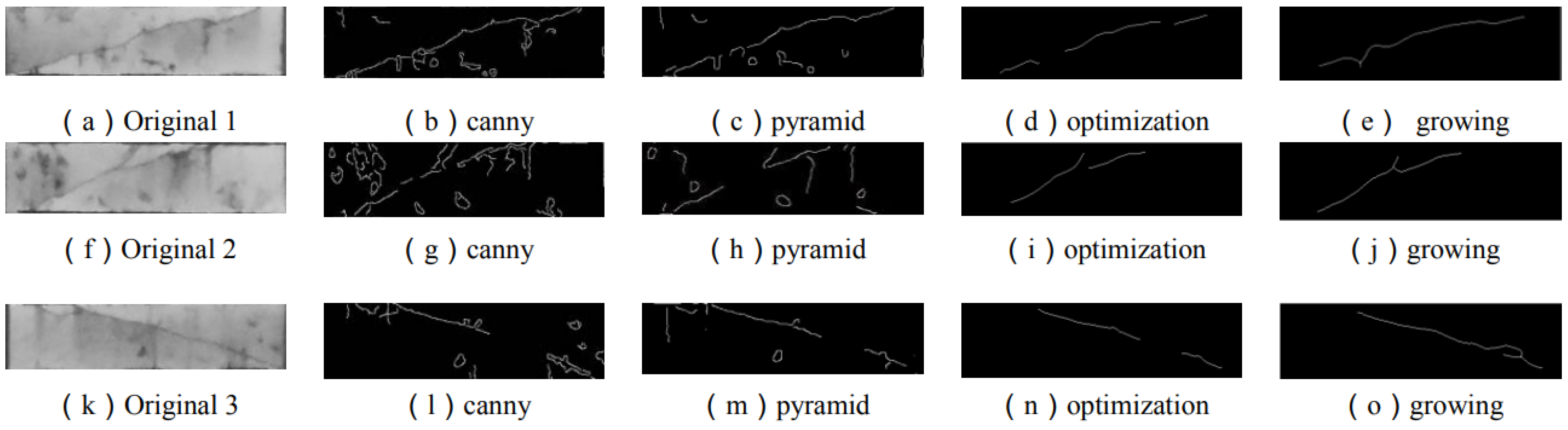
- Song, M.; Cui, D.; Yu, C.; An, J.; Chang, C.I.; Song, M. Crack detection algorithm for photovoltaic image based on multi-scale pyramid and improved region growing. In Proceedings of the 2018 IEEE 3rd International Conference on Image, Vision and Computing (ICIVC), Chongqing, China, 27–29 June 2018; pp. 128–132. [Google Scholar]
- Shivaprasad, K.; Vishwanath, M.; Narasimha, K. Morphology based surface crack detection. J. Adv. Res. Sci. 2015, 1, 15–20. [Google Scholar]
- Koshy, S.; Radhakrishnan, B.; Suresh, L.P. Strength analysis of buildings using image processing and SHM principles. In Proceedings of the 2016 International Conference on Emerging Technological Trends (ICETT), Kollam, India, 21–22 October 2016; pp. 1–6. [Google Scholar]
- Orak, M.S.; Ozturk, T. Monitoring cantilever beam with a vision-based algorithm and smartphone. Vibroeng. Procedia 2018, 17, 107–111. [Google Scholar] [CrossRef]
- Zhang, Y.; Zhao, X.; Liu, P. Multi-point displacement monitoring based on full convolutional neural network and smartphone. IEEE Access 2019, 7, 139628–139634. [Google Scholar] [CrossRef]
- Li, S.; Zhao, X.; Zhou, G. Automatic pixel-level multiple damage detection of concrete structure using fully convolutional network. Comput.-Aided Civ. Infrastruct. Eng. 2019, 34, 616–634. [Google Scholar] [CrossRef]
- Zhang, L.; Yang, F.; Zhang, Y.D.; Zhu, Y.J. Road crack detection using deep convolutional neural network. In Proceedings of the 2016 IEEE International Conference on Image Processing (ICIP), Phoenix, AZ, USA, 25–28 September 2016; pp. 3708–3712. [Google Scholar]
- Kim, H.; Lee, J.; Ahn, E.; Cho, S.; Shin, M.; Sim, S.H. Concrete crack identification using a UAV incorporating hybrid image processing. Sensors 2017, 17, 2052. [Google Scholar] [CrossRef]
- Kim, H.; Sim, S.H.; Cho, S. Unmanned aerial vehicle (UAV)-powered concrete crack detection based on digital image processing. In Proceedings of the International Conference on Advances in Experimental Structural Engineering, Chicago, IL, USA, 1–2 August 2015. [Google Scholar]
- Cao, J.; Zhang, K.; Yuan, C.; Xu, S. Automatic road cracks detection and characterization based on mean shift. Jisuanji Fuzhu Sheji Yu Tuxingxue Xuebao J. Comput.-Aided Des. Comput. Graph. 2014, 26, 1450–1459. [Google Scholar]
- Hu, Y.; Zhao, C.X.; Wang, H.N. Automatic pavement crack detection using texture and shape descriptors. IETE Tech. Rev. 2010, 27, 398–405. [Google Scholar] [CrossRef]
- Jahanshahi, M.R.; Masri, S.F.; Padgett, C.W.; Sukhatme, G.S. An innovative methodology for detection and quantification of cracks through incorporation of depth perception. Mach. Vis. Appl. 2013, 24, 227–241. [Google Scholar] [CrossRef]
- Prasanna, P.; Dana, K.J.; Gucunski, N.; Basily, B.B.; La, H.M.; Lim, R.S.; Parvardeh, H. Automated crack detection on concrete bridges. IEEE Trans. Autom. Sci. Eng. 2014, 13, 591–599. [Google Scholar] [CrossRef]
- Lee, B.Y.; Kim, Y.Y.; Yi, S.T.; Kim, J.K. Automated image processing technique for detecting and analysing concrete surface cracks. Struct. Infrastruct. Eng. 2013, 9, 567–577. [Google Scholar] [CrossRef]
- Cord, A.; Chambon, S. Automatic road defect detection by textural pattern recognition based on AdaBoost. Comput.-Aided Civ. Infrastruct. Eng. 2012, 27, 244–259. [Google Scholar] [CrossRef]
- Salehi, H.; Biswas, S.; Burgueño, R. Data interpretation framework integrating machine learning and pattern recognition for self-powered data-driven damage identification with harvested energy variations. Eng. Appl. Artif. Intell. 2019, 86, 136–153. [Google Scholar] [CrossRef]
- Gavilán, M.; Balcones, D.; Marcos, O.; Llorca, D.F.; Sotelo, M.A.; Parra, I.; Ocaña, M.; Aliseda, P.; Yarza, P.; Amírola, A. Adaptive road crack detection system by pavement classification. Sensors 2011, 11, 9628–9657. [Google Scholar] [CrossRef] [PubMed]
- Ersoz, A.B.; Pekcan, O.; Teke, T. Crack identification for rigid pavements using unmanned aerial vehicles. In Proceedings of the IOP Conference Series: Materials Science and Engineering, Prague, Czech Republic, 21–22 September 2017; IOP Publishing: Bristol, UK, 2017; Volume 236, p. 012101. [Google Scholar]
- Kotsiantis, S.B. Decision trees: A recent overview. Artif. Intell. Rev. 2013, 39, 261–283. [Google Scholar] [CrossRef]
- Wu, W.; Liu, Z.; He, Y. Classification of defects with ensemble methods in the automated visual inspection of sewer pipes. Pattern Anal. Appl. 2015, 18, 263–276. [Google Scholar] [CrossRef]
- Cover, T.; Hart, P. Nearest neighbor pattern classification. IEEE Trans. Inf. Theory 1967, 13, 21–27. [Google Scholar] [CrossRef]
- Uddin, S.; Haque, I.; Lu, H.; Moni, M.A.; Gide, E. Comparative performance analysis of K-nearest neighbour (KNN) algorithm and its different variants for disease prediction. Sci. Rep. 2022, 12, 6256. [Google Scholar] [CrossRef]
- Zhang, W.; Zhang, Z.; Qi, D.; Liu, Y. Automatic crack detection and classification method for subway tunnel safety monitoring. Sensors 2014, 14, 19307–19328. [Google Scholar] [CrossRef]
- Kirasich, K.; Smith, T.; Sadler, B. Random forest vs logistic regression: Binary classification for heterogeneous datasets. SMU Data Sci. Rev. 2018, 1, 9. [Google Scholar]
- Binte Kibria, H.; Matin, A. The Severity Prediction of The Binary And Multi-Class Cardiovascular Disease–A Machine Learning-Based Fusion Approach. arXiv 2022, arXiv:2203.04921. [Google Scholar]
- Shi, Y.; Cui, L.; Qi, Z.; Meng, F.; Chen, Z. Automatic road crack detection using random structured forests. IEEE Trans. Intell. Transp. Syst. 2016, 17, 3434–3445. [Google Scholar] [CrossRef]
- Yang, X.; Li, H.; Yu, Y.; Luo, X.; Huang, T.; Yang, X. Automatic pixel-level crack detection and measurement using fully convolutional network. Comput.-Aided Civ. Infrastruct. Eng. 2018, 33, 1090–1109. [Google Scholar] [CrossRef]
- Santur, Y.; Karaköse, M.; Akin, E. Random forest based diagnosis approach for rail fault inspection in railways. In Proceedings of the 2016 National Conference on Electrical, Electronics and Biomedical Engineering (ELECO), Bursa, Turkey, 1–3 December 2016; pp. 745–750. [Google Scholar]
- Ibrahim, I.; Abdulazeez, A. The Role of machine learning algorithms for diagnosing diseases. J. Appl. Sci. Technol. Trends 2021, 2, 10–19. [Google Scholar] [CrossRef]
- Landstrom, A.; Thurley, M.J. Morphology-based crack detection for steel slabs. IEEE J. Sel. Top. Signal Process. 2012, 6, 866–875. [Google Scholar] [CrossRef]
- Park, K.; Torbol, M. Visual-based laser speckle pattern recognition method for structural health monitoring. In Proceedings of the Sensors and Smart Structures Technologies for Civil, Mechanical, and Aerospace Systems 2017, Portland, OR, USA, 25–29 March 2017; Volume 10168, pp. 114–120. [Google Scholar]
- Lei, B.; Wang, N.; Xu, P.; Song, G. New crack detection method for bridge inspection using UAV incorporating image processing. J. Aerosp. Eng. 2018, 31, 04018058. [Google Scholar] [CrossRef]
- Shukla, S.; Naganna, S. A review on K-means data clustering approach. Int. J. Inf. Comput. Technol. 2014, 4, 1847–1860. [Google Scholar]
- Wang, X.; Liu, Y.; Xin, H. Bond strength prediction of concrete-encased steel structures using hybrid machine learning method. Structures 2021, 32, 2279–2292. [Google Scholar] [CrossRef]
- Moon, H.G.; Kim, J.H. Intelligent crack detecting algorithm on the concrete crack image using neural network. Proc. 28th ISARC 2011, 2011, 1461–1467. [Google Scholar]
- Xu, Y.; Li, S.; Zhang, D.; Jin, Y.; Zhang, F.; Li, N.; Li, H. Identification framework for cracks on a steel structure surface by a restricted Boltzmann machines algorithm based on consumer-grade camera images. Struct. Control Health Monit. 2018, 25, e2075. [Google Scholar] [CrossRef]
- Yang, A.Y.; Cheng, L. Two-step surface damage detection scheme using convolutional neural network and artificial neural neural. arXiv 2020, arXiv:2003.10760. [Google Scholar]
- Fan, Z.; Wu, Y.; Lu, J.; Li, W. Automatic pavement crack detection based on structured prediction with the convolutional neural network. arXiv 2018, arXiv:1802.02208. [Google Scholar]
- Tan, C.; Uddin, N.; Mohammed, Y.M. Deep learning-based crack detection using mask R-CNN technique. In Proceedings of the 9th International Conference on Structural Health Monitoring of Intelligent Infrastructure, St. Louis, MO, USA, 5–7 August 2019. [Google Scholar]
- Cha, Y.J.; Choi, W.; Büyüköztürk, O. Deep learning-based crack damage detection using convolutional neural networks. Comput.-Aided Civ. Infrastruct. Eng. 2017, 32, 361–378. [Google Scholar] [CrossRef]
- Dorafshan, S.; Thomas, R.J.; Coopmans, C.; Maguire, M. Deep learning neural networks for sUAS-assisted structural inspections: Feasibility and application. In Proceedings of the 2018 International Conference on Unmanned Aircraft Systems (ICUAS), Dallas, TX, USA, 12–15 June 2018; pp. 874–882. [Google Scholar]
- Gopalakrishnan, K.; Khaitan, S.K.; Choudhary, A.; Agrawal, A. Deep convolutional neural networks with transfer learning for computer vision-based data-driven pavement distress detection. Constr. Build. Mater. 2017, 157, 322–330. [Google Scholar] [CrossRef]
- Feng, C.; Liu, M.Y.; Kao, C.C.; Lee, T.Y. Deep active learning for civil infrastructure defect detection and classification. Comput. Civ. Eng. 2017, 2017, 298–306. [Google Scholar]
- Li, S.; Zhao, X. Image-based concrete crack detection using convolutional neural network and exhaustive search technique. Adv. Civ. Eng. 2019, 2019, 6520620. [Google Scholar] [CrossRef]
- Guo, X.; Yuan, Y.; Liu, Y. Crack propagation detection method in the structural fatigue process. Exp. Tech. 2021, 45, 169–178. [Google Scholar] [CrossRef]
- Jia, X.; Luo, W. Crack Damage Detection of Bridge Based on Convolutional Neural Networks. In Proceedings of the 2019 Chinese Control and Decision Conference (CCDC), Nanchang, China, 3–5 June 2019; pp. 3995–4000. [Google Scholar]
- Tong, Z.; Gao, J.; Han, Z.; Wang, Z. Recognition of asphalt pavement crack length using deep convolutional neural networks. Road Mater. Pavement Des. 2018, 19, 1334–1349. [Google Scholar] [CrossRef]
- Chen, J.G.; Wadhwa, N.; Cha, Y.J.; Durand, F.; Freeman, W.T.; Buyukozturk, O. Structural modal identification through high speed camera video: Motion magnification. In Topics in Modal Analysis I, Volume 7: Proceedings of the 32nd IMAC, A Conference and Exposition on Structural Dynamics, Orlando, FL, USA, 3–6 February 2014; Springer: Berlin/Heidelberg, Germany, 2014; pp. 191–197. [Google Scholar]
- Civera, M.; Zanotti Fragonara, L.; Surace, C. An experimental study of the feasibility of phase-based video magnification for damage detection and localisation in operational deflection shapes. Strain 2020, 56, e12336. [Google Scholar] [CrossRef]
- Chen, J.G.; Adams, T.M.; Sun, H.; Bell, E.S.; Büyüköztürk, O. Camera-based vibration measurement of the world war I memorial bridge in Portsmouth, New Hampshire. J. Struct. Eng. 2018, 144, 04018207. [Google Scholar] [CrossRef]
- Chen, J.G.; Wadhwa, N.; Cha, Y.J.; Durand, F.; Freeman, W.T.; Buyukozturk, O. Modal identification of simple structures with high-speed video using motion magnification. J. Sound Vib. 2015, 345, 58–71. [Google Scholar] [CrossRef]
- Ferrer, B.; Espinosa, J.; Roig, A.B.; Perez, J.; Mas, D. Vibration frequency measurement using a local multithreshold technique. Opt. Express 2013, 21, 26198–26208. [Google Scholar] [CrossRef]
- Patsias, S.; Staszewskiy, W. Damage detection using optical measurements and wavelets. Struct. Health Monit. 2002, 1, 5–22. [Google Scholar] [CrossRef]
- Gupta, P.; Rajput, H.S.; Law, M. Vision-based modal analysis of cutting tools. CIRP J. Manuf. Sci. Technol. 2021, 32, 91–107. [Google Scholar] [CrossRef]
- Liu, J.; Yang, X. Learning to see the vibration: A neural network for vibration frequency prediction. Sensors 2018, 18, 2530. [Google Scholar] [CrossRef] [PubMed]
- Liu, J.; Yang, X.; Zhu, M. Neural network with confidence kernel for robust vibration frequency prediction. J. Sens. 2019, 2019, 6573513. [Google Scholar] [CrossRef]
- Muralidharan, P.K.; Yanamadala, H. Comparative Study of Vision Camera-based Vibration Analysis with the Laser Vibrometer Method. 2021. Available online: https://www.diva-portal.org/smash/record.jsf?pid=diva2%3A1608598&dswid=-3097 (accessed on 3 August 2023).
- Lee, J.J.; Shinozuka, M. Real-time displacement measurement of a flexible bridge using digital image processing techniques. Exp. Mech. 2006, 46, 105–114. [Google Scholar] [CrossRef]


| DFP- Prewitt | DFP- Roberts | DFP- Sobel | DFP- Canny | |
|---|---|---|---|---|
| Processing time (s) | 74.69 | 78.13 | 85.94 | 79.69 |
| Domain | Edge Detector | TPR 1 (%) | TNR 2 (%) | FPR 3 (%) | FNR 4 (%) | Ac 5 (%) | Pr 6 (%) | MCW 7 (mm) | Time (s) |
|---|---|---|---|---|---|---|---|---|---|
| Spatial | Roberts | 64 | 90 | 10 | 36 | 77 | 86 | 0.4 | 1.67 |
| Spatial | Prewitt | 82 | 82 | 18 | 18 | 82 | 82 | 0.2 | 1.4 |
| Spatial | Sobel | 86 | 84 | 16 | 14 | 85 | 84 | 0.2 | 1.4 |
| Spatial | (LoG) | 98 | 86 | 14 | 2 | 92 | 88 | 0.1 | 1.18 |
| Frequency | Butterworth | 80 | 86 | 14 | 20 | 83 | 85 | 0.2 | 1.81 |
| Frequency | Gaussian | 80 | 88 | 12 | 20 | 84 | 87 | 0.2 | 1.92 |
| Test Project | Crack Detection Rate | False Positive Rate |
|---|---|---|
| Otsu algorithm | 40% | 60% |
| Twice-threshold | 98% | 2% |
| Correct Detection | Cracked Area | Noncracked Area |
|---|---|---|
| Detection results | ||
| Cracked area | TP | FP |
| Noncracked area | FN | TN |
| Scenario | Excitation Frequency (Hz) | Predicted Frequency (Hz) |
|---|---|---|
| 1 | 5.0 | 5.0 |
| 2 | 10.0 | 10.1 |
| 3 | 15.0 | 14.9 |
| 4 | 20.0 | 20.0 |
| 5 | 25.0 | 24.9 |
| 6 | 30.0 | 30.0 |
| 7 | 35.0 | 35.0 |
| 8 | 40.0 | 40.0 |
| 9 | 45.0 | 45.0 |
Disclaimer/Publisher’s Note: The statements, opinions and data contained in all publications are solely those of the individual author(s) and contributor(s) and not of MDPI and/or the editor(s). MDPI and/or the editor(s) disclaim responsibility for any injury to people or property resulting from any ideas, methods, instructions or products referred to in the content. |
© 2023 by the authors. Licensee MDPI, Basel, Switzerland. This article is an open access article distributed under the terms and conditions of the Creative Commons Attribution (CC BY) license (https://creativecommons.org/licenses/by/4.0/).
Share and Cite
Azouz, Z.; Honarvar Shakibaei Asli, B.; Khan, M. Evolution of Crack Analysis in Structures Using Image Processing Technique: A Review. Electronics 2023, 12, 3862. https://doi.org/10.3390/electronics12183862
Azouz Z, Honarvar Shakibaei Asli B, Khan M. Evolution of Crack Analysis in Structures Using Image Processing Technique: A Review. Electronics. 2023; 12(18):3862. https://doi.org/10.3390/electronics12183862
Chicago/Turabian StyleAzouz, Zakrya, Barmak Honarvar Shakibaei Asli, and Muhammad Khan. 2023. "Evolution of Crack Analysis in Structures Using Image Processing Technique: A Review" Electronics 12, no. 18: 3862. https://doi.org/10.3390/electronics12183862