1. Introduction
The ultra-high-voltage direct current (UHVDC) system, with a large transmission capacity, long transmission distance, and low transmission loss, can effectively solve the urgent requirements of new energy transmission and load center power supply in China [
1,
2]. Nowadays, there are two types of UHVDC technologies: one is line commutated converter (LCC)-based technology, and the other is modular multilevel converter (MMC)-based technology. The former has multiple advantages, such as a large transmission capacity, cheap costs, and good control performance [
3,
4]. However, commutation failure issues and large reactive power consumption are inevitable [
1,
5]. The latter can independently control active and reactive power without the risk of commutation failure, but the investment cost and operation loss are both high [
6].
In order to maximize the integration of the benefits of LCC-based UHVDC and MMC-based UHVDC, hybrid HVDC technology has been in development [
7]. Baihetan–Jiangsu UHVDC engineering in China adopted the hybrid-cascade technology for the first time in the world. The rectifier station still has LCC, while the inverter station has LCC at the high end and three MMCs in parallel at the low end. The hybrid-cascade UHVDC system meets the requirements for a large transmission capacity, commutation failure mitigation, and flexible control at the same time [
8,
9,
10,
11]. However, the operating principle and control strategies of the two types of converters are essentially different. Moreover, the connection topology of converters is novel. The overall response of the hybrid-cascade UHVDC system becomes more complex than conventional UHVDC systems [
12,
13]; a series of new problems that need to be discussed and solved urgently have been raised. References [
14,
15] analyzed the steady-state operation characteristics and fault response characteristics of the hybrid-cascaded UHVDC system and explored the system recovery control strategy during DC fault and after fault clearing. The authors in [
16] gave calculation methods for the bus voltage on the inverter side high end, the MMC temporary overvoltage, and the thermal stability margin of the inverter station outlet line for the hybrid-cascaded UHVDC system. In addition, aiming at the commutation failure problem of the inverter high-end in the hybrid-cascade UHVDC system, scholars proposed a commutation failure suppression method using the reactive power support ability of MMCs [
17] and the unbalanced current suppression method of the low-end MMCs after commutation failure [
18]. Based on the reactive power configuration of the inverter station, ref. [
19] proposed a voltage optimization distribution strategy between LCC and MMC. The transient overcurrent issue has also attracted the attention of researchers, and representative solutions include the virtual-impedance-based [
20] and the fuzzy-clustering-based [
21] suppression approaches.
Scholars have obtained certain results for both the operation and control problems of hybrid-cascaded UHVDC systems, while inadequately investigating the power equalization among low-end MMCs at the inverter side under the disturbance of rectifier side failure. Despite the fact that the current parallel MMC coordination control strategy can ensure favorable steady-state operation characteristics, seriously uneven power distribution among multiple MMCs can occur when the DC transmission power is significantly deficient in the event of a rectifier failure; consequently, the constant DC voltage MMC will absorb almost all the power vacancy on the low end and even switch from inverting to the rectifying state. Considering that parallel MMCs can be connected to different receiving-end AC systems in a decentralized manner, the significant fluctuations of a single MMC can have a significant impact on the connected AC system and trigger the large-scale transfer of the power flow, thereby posing unnecessary threats to the safety of the power grid.
To address the above problems, this study proposed a simple and efficient power equalization control strategy for parallel MMCs in a hybrid-cascaded UHVDC system. By adding power equalization control functions and control-enabling logic to the existing control framework, the proposed control strategy can automatically equalize the parallel MMC power during the disturbance period. In addition, the PSCAD/EMTDC simulation platform was used to develop the Baihetan–Jiangsu hybrid-cascaded UHVDC model in order to validate the effectiveness of the proposed control strategy.
2. Hybrid-Cascaded UHVDC System
2.1. Topology
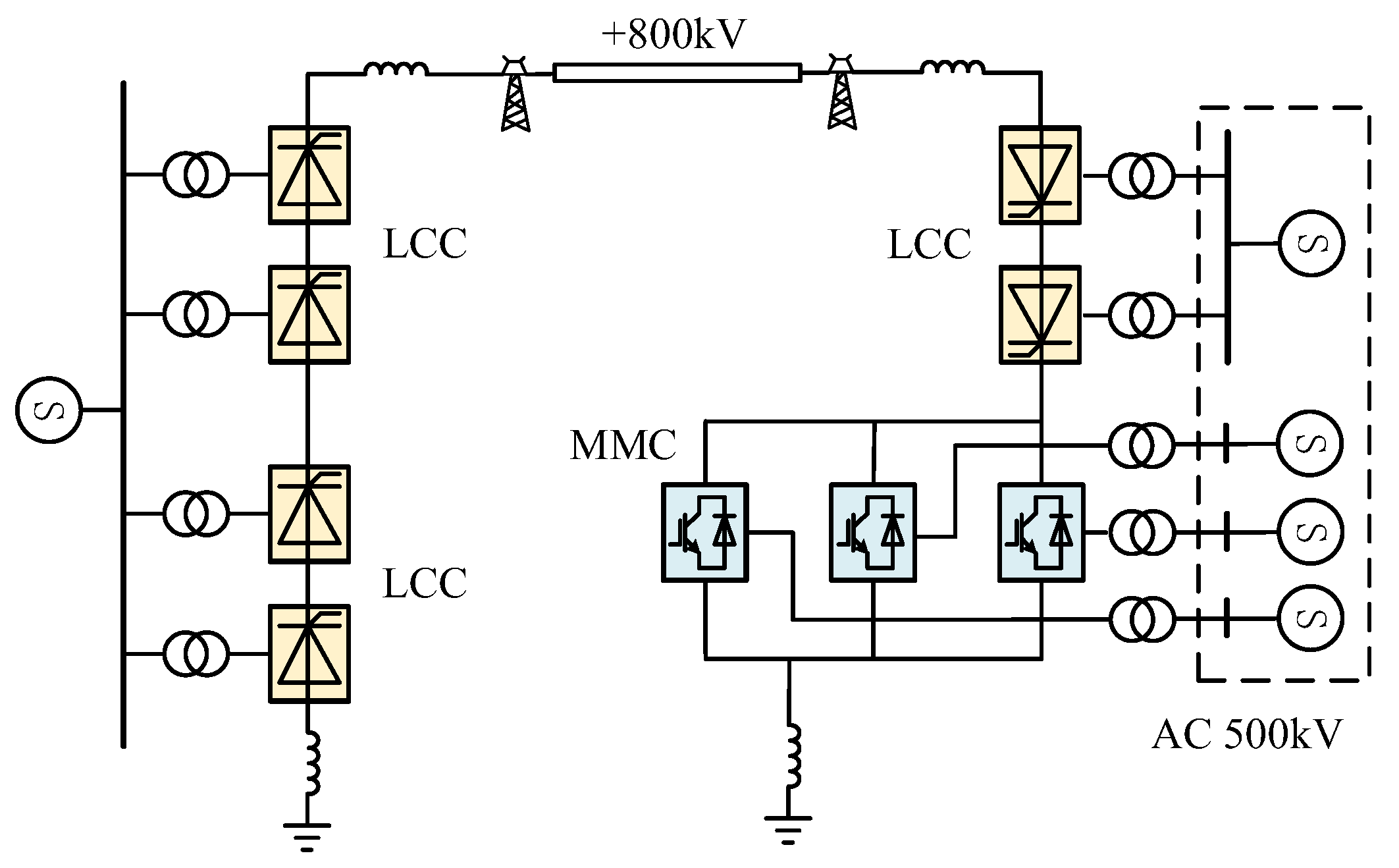
The unipolar topology of the hybrid-cascaded UHVDC system studied is given in
Figure 1. Two 12-pulse LCCs are connected in series on the rectifier side, and the LCC and MMCs are connected in series on the inverter side. The high end is a conventional 12-pulse LCC, and the low end is composed of three parallel MMCs. The receiving converters are connected to the AC grid in a decentralized manner, as shown by the dotted box in the figure. It is worth noting that the conclusions obtained by analyzing the unipolar hybrid-cascaded HVDC system are also applicable to the bipolar system structure extended from
Figure 1.
2.2. Basic Control Strategy
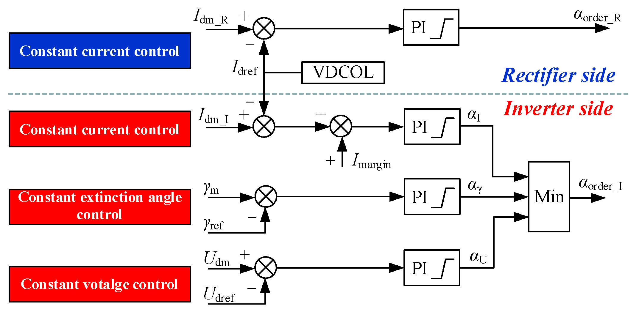
Similar to the conventional UHVDC, the DC and DC voltage are respectively controlled by the rectifier and the inverter side in normal operations for the hybrid-cascaded UHVDC system. The basic control loop for the LCC is shown in
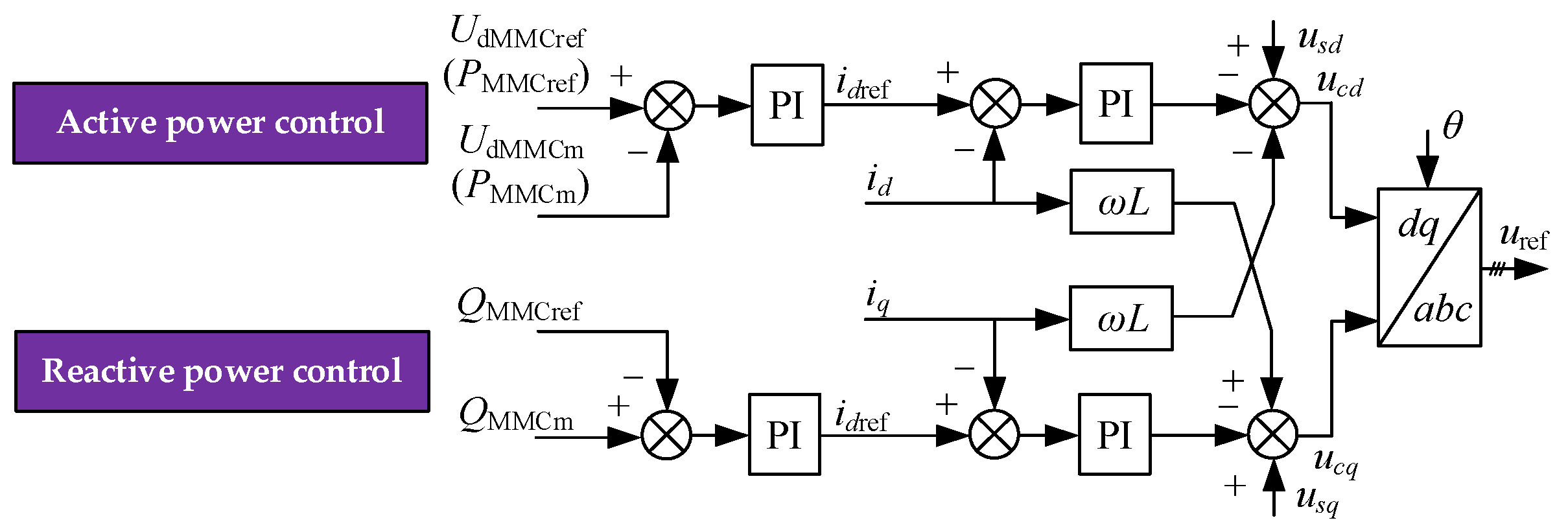
Figure 2. LCCs on the rectifier side and the inverter side are configured with different control modes. Also, the control mode on each side can be switched. The low-voltage end MMCs are equipped with the current vector control strategy with a double closed-loop structure as depicted in
Figure 3. The outer-loop control can be divided into active and reactive types and output the reference values of the active and reactive current in inner-loop control (denoted as
idref and
iqref, respectively); consequently, both the current waveform and phase on the AC side of the converter can be controlled directly with inner-loop control. The active power control mode is that one MMC uses a constant DC voltage control and the other MMCs adopt a constant active power control. All the MMCs use the constant reactive power outer loop control mode.
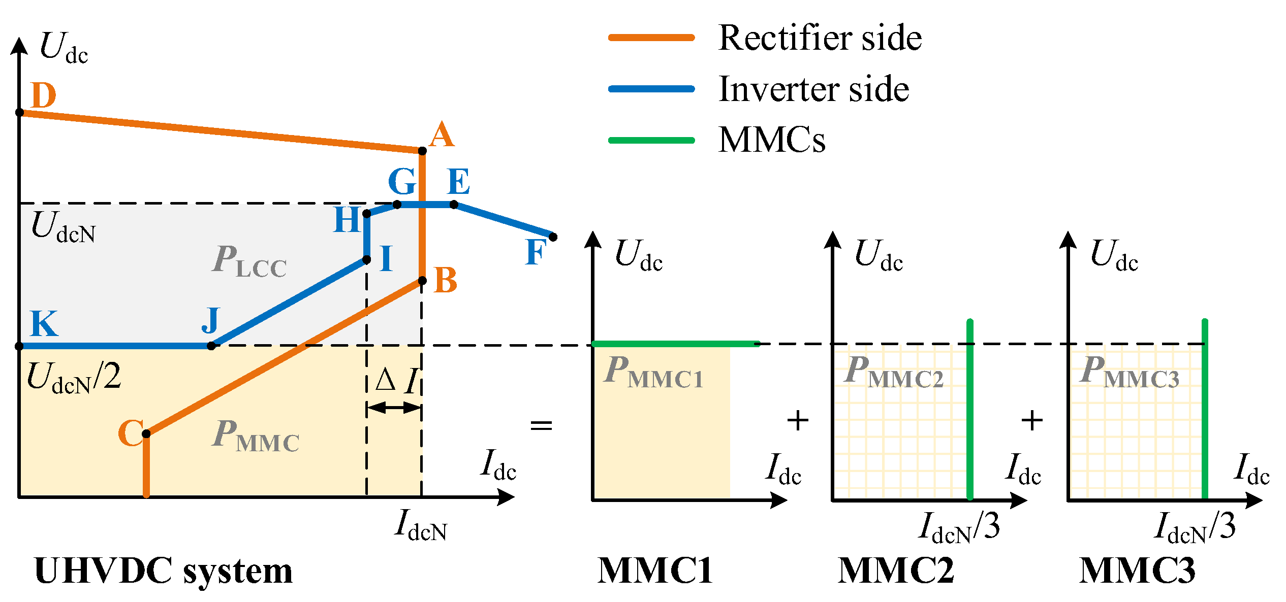
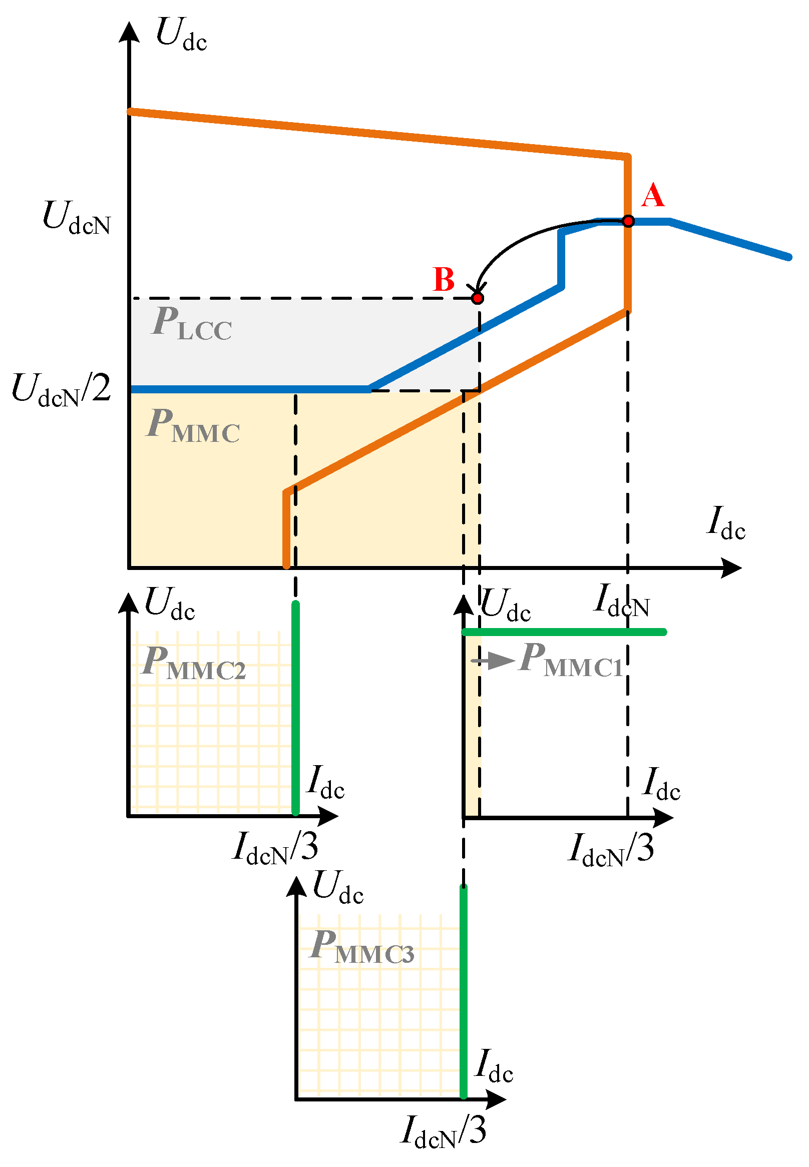
Based on the control loop configurations mentioned above, the external characteristic curve of the hybrid-cascaded UHVDC system can be given in
Figure 4. Specifically, the external characteristics on the side of the rectifier, the side of the inverter, and the three MMCs. Different segments correspond to distinct control modes, as detailed in
Table 1.
Under normal operating conditions, the constant direct current at the rectifier side can be ensured by rapidly adjusting the firing angle with the constant current regulator. At the inverter side, the LCC can rapidly adjust the turn-off angle so as to ensure the constant high-end DC voltage. The low-end voltage is fixed by an MMC (MMC1). The steady-state operating point of the system is the intersection point of Segment AB and Segment GE. Both the high-end LCC at the inverter side and the low-end MMC equally share the DC power evacuation, as marked by gray and yellow, respectively. Meanwhile, MMC2 and MMC3 are in constant active power mode, and the power reference value is one-third of the low-end power so the remaining power for MMC1 to transmit is also one-third. Under normal conditions, the residual power on the low end of the MMC1 is identical to that of an MMC with constant power.
3. Mechanism of Unbalanced Power Generation among MMCs Caused by Rectifier AC System Faults
The DC voltage on the rectifier side of hybrid cascaded UHVDC can be given as:
where
N1 is the number of six-pulse converters;
U1 is the no-load line voltage at the valve side of the transformer;
α is the firing angle of the rectifier;
Xr1 is the commutation reactance; and
Id is the DC, which is determined by the DC voltage on both sides and the resistance of the DC circuit.
When a fault occurs on the side of the rectifier in an AC system, the no-load line voltage,
U1, immediately drops. Moreover, the voltage drop is more serious at the failure point closer to the converter station in terms of electrical distance. The decrease in
U1 can also result in a decline in
Ud1. It should be noted that the reduction in the firing angle is limited. At a firing angle of 5°, the rectifier side no longer possesses active voltage regulation capability, and the system enters the minimum firing angle control mode (as shown in Segment AD of
Figure 4). Therefore, the DC voltage at the rectifier side (denoted as
Ud1) falls rapidly.
When the rectifier side transitions from constant current control mode to minimum firing angle control mode, the inverter side takes over the control of the current; however, the direct current may also decrease for the reasons listed below. First, when the DC voltage decreases, the voltage-dependent current order limiter (VDCOL) function of the system is activated, causing the current instruction value to decrease. Secondly, according to the above-mentioned determining factors of Id, the DC voltage at the inverter side (Ud2) should follow the decrease in Ud1 as closely as possible in order to achieve a controlled direct current when the loop resistance remains unchanged. However, the DC control response lags behind the fault occurrence. Finally, after the occurrence of a fault, the commutation voltages of both the high- and low-end converters at the rectifier side drop simultaneously; however, only the high-end LCC at the inverter side has the capability of rapid voltage regulation within a limited range.
Based on the above analysis, both the DC voltage and current drop after an AC system fault, resulting in a decrease in the DC transmission power.
Figure 5 illustrates the generation of unbalanced power among low-end MMCs at the inverter side after the decrease in DC power.
During the disturbance period, the operating point of the system shifts to the lower left. Due to the complexity of the control switching process and the limited regulation velocity, the operating point may deviate from the operating characteristic curves on both the rectifier and inverter sides. As shown in
Figure 5, it can be assumed that the operating point of the system deviates from Point A to Point B in this study. Consequently, the power of the LCC at the inverter side drops to the gray area, and both the voltage and current reductions have an effect on LCC power and the total power of the MMC drops to the yellow area. Since the DC side voltage of the MMC is fixed in a short period of time, the total power is only affected by a reduction in current. However, the power of the constant-power MMC can be controlled and remains unchanged, and accordingly, the vacancy of the total power of the MMC is borne by the constant-voltage MMC. As shown in the
PMMC1 region, the constant-voltage MMC power under operating conditions is significantly less than the rated value and may even be negative under extreme conditions (the rectifying state). The AC system connected with the constant-voltage MMC will bear a huge disturbance of active power, imposing an adverse effect on power grid safety operation.
4. Power Equalization Control Strategy
According to the above analysis, the failure of the AC system on the rectifier side can reduce the UHVDC system’s overall transmission power. During the disturbance period, if the constant-power MMC at the inverter side remains in the original control mode, the constant-voltage MMC absorbs the entire low-end power vacancy and even transitions from inverting to the rectifying state. Meanwhile, a serious power disequilibrium appears, imposing adverse effects on the safe operation of the power grid.
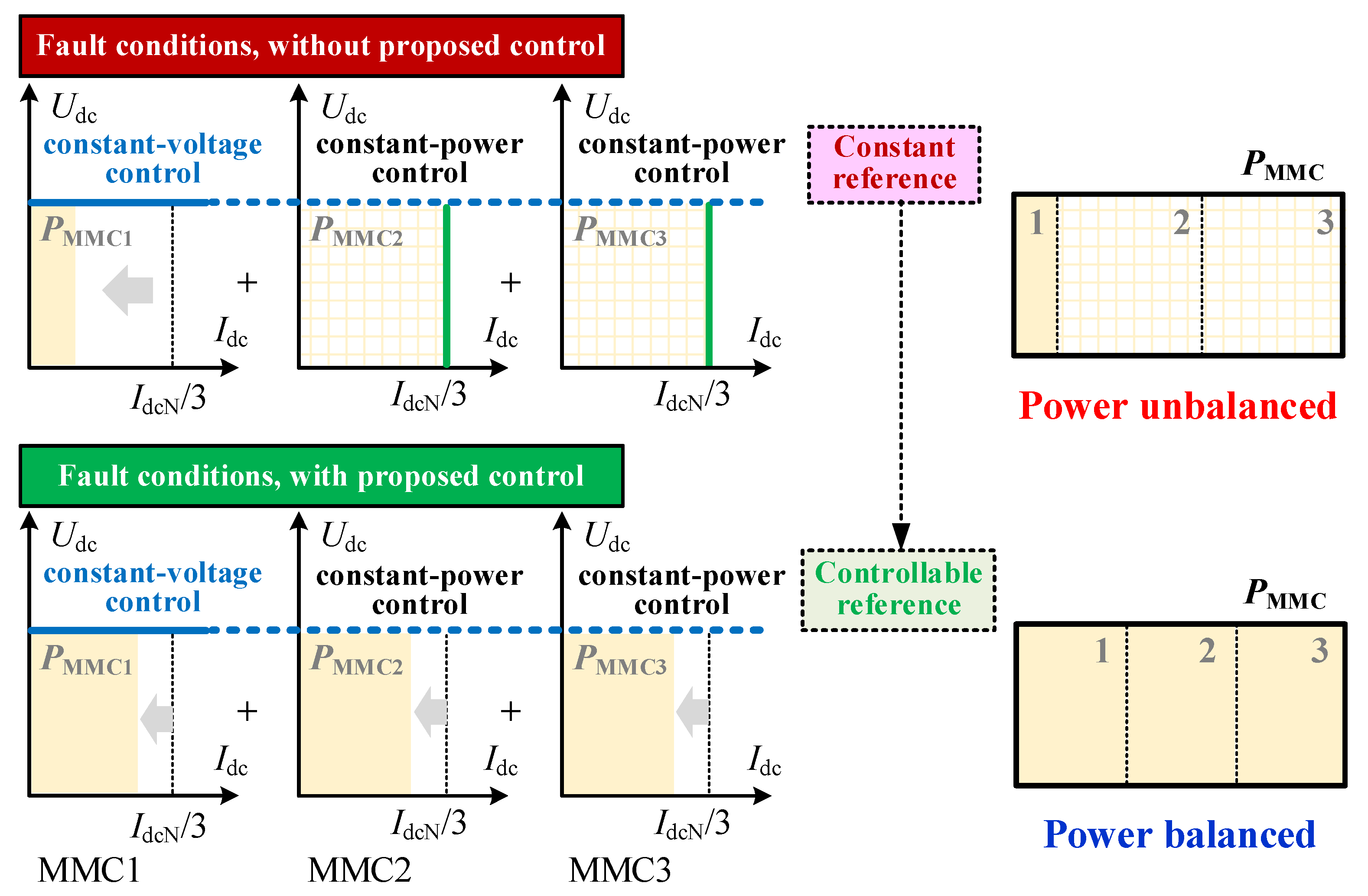
This study proposes a power equilibrium control strategy for MMCs in a hybrid-cascaded UHVDC system in order to achieve dynamic active power equilibrium among MMCs at the inverter side under the disturbance of a failure at the rectifier side. The basic idea is shown in
Figure 6. The proposed strategy focused on the MMC with constant active power mode in closed-loop control and added a power equilibrium enabling module and power equilibrium control loop. Accordingly, in the case of the reduction in DC transmission power induced by the fault at the rectifier side, the control reference of the constant-power MMC changes from constant to controlled and time-varying. The overall objective of constant-power MMC then changes from maintaining constant power to maintaining a power equilibrium among multiple MMCs.
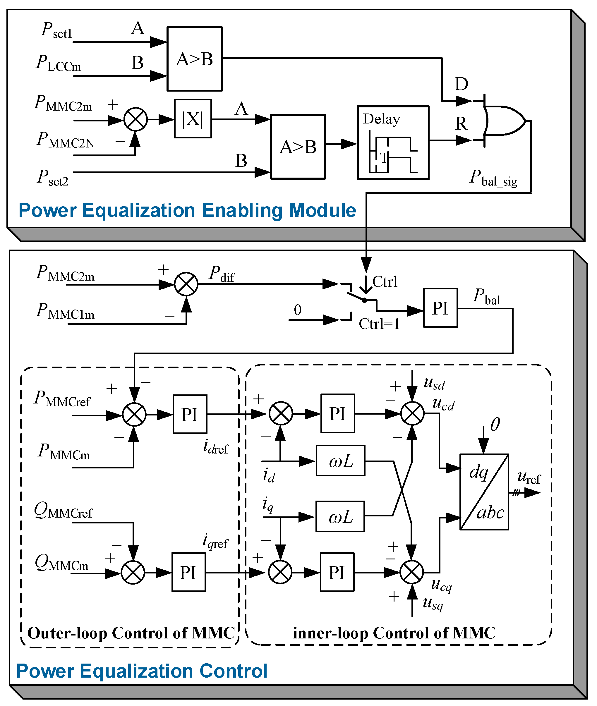
Figure 7 demonstrates the logic diagram of the proposed power equalization control strategy. The involved variables are listed in
Table 2. Various control modules are described in greater detail below.
4.1. Power Equilibrium Enabling Module
Aiming at ensuring the power equilibrium only operates when necessary and imposes no effect on the system’s normal operation, this study designed a power equilibrium enabling module. Considering that the LCC power fluctuates rapidly under disturbance, the MMC is controlled relatively more stably. As a result, this study chooses the power drop of the LCC on the high end at the inverter side as the starting condition of control in order to control the rapid input of the power equilibrium control module after failure. Next, the condition that the power of the constant-power MMC on the low end is restored to the rated value and maintains a certain time is selected as the ending condition of control, which can effectively avoid the frequent input and exit of control during the failure recovery period.
Figure 7 depicts the logic diagram of power equilibrium enabling control, where
Pset1 is slightly less than the rated operating power of the LCC at the inverter’s high end. When the measured
PLCCm is below
Pset1, the power drop signal of the LCC (denoted as D) is set as 1. Additionally, when the measured power of the constant-power MMC deviates from the rated value within a certain range for a certain length, the power restoration signal of the constant-power MMC (denoted as R) is set as 0; otherwise, the signal is set as 1. Finally, the power equilibrium enabling signal can be obtained when taking the
OR operation on the signal D and the signal R.
Under normal operating conditions, both the power of the high-end LCC and the power of the low-end MMC at the inverter side are normal, and the values of D and R are both equal to 0, indicating that the power equalization module does not receive any input. Once the DC transmission power drops after the occurrence of a failure in the AC system at the rectifier side, the value of D changes to 1, and the power equalization module is triggered. After adjusting the power distribution among MMCs, the value of R is reset to 1, rendering the control input ineffective. During the restoration process of DC transmission power after the clearance of failure, D may show a jumping change between 0 and 1. However, since the restoration of the power of constant-power MMC is not confirmed, the value of R always equals 1 and maintains the input state of the power equalization state. The power equalization control exits until both of the following conditions are met: (1) the LCC power returns to normal and (2) the active power of the MMC is restored and maintained for a predetermined amount of time.
4.2. Power Equilibrium Control
When the power equalization enabling module output is 1, the power equalization starts up. The implementation principle is described below. The active power deviation between the constant-voltage MMC and the constant-power MMC (denoted as Pdif) is monitored in real-time and input to the PI control unit. The additional power instruction Pbal is then generated and superimposed onto the active-type control outer loop of the constant-power MMC.
Under normal conditions, the power equalization modules are inactive. In the meantime, the active power deviation between the constant-voltage MMC and constant-power MMC almost equals 0. The absence of DC transmission power will result in a deviation of active power between the constant-voltage MMC and constant-power MMC, triggering the input of the power equalization control module. The control unit can then quickly initiate the instruction to reduce the power of a constant-power MMC in response to an actual power deviation, and the reduced power is transferred to a constant-voltage MMC to eliminate the power deviation and achieve the dynamic equalization of active power among MMCs.
The threshold and PI control parameters in the proposed strategy can be debugged in combination with engineering characteristics during actual applications. In the subsequent simulation case, the values of Pset1 and Pset2 were set to 0.9 p.u. and 0.06 p.u., respectively. Additionally, the time delay of the delay module was set to 200 ms, and the values of kp and Ti in the PI controller were set to 3 and 0.02, respectively.
5. Simulation Validation
5.1. Test System
To verify the effectiveness of the proposed power equalization control strategy, a hybrid-cascaded UHVDC system is modeled in PSCAD/ETMDC software V4.6.2, which is a powerful time-domain transient simulator for simulating power systems and their controls [
22,
23,
24].
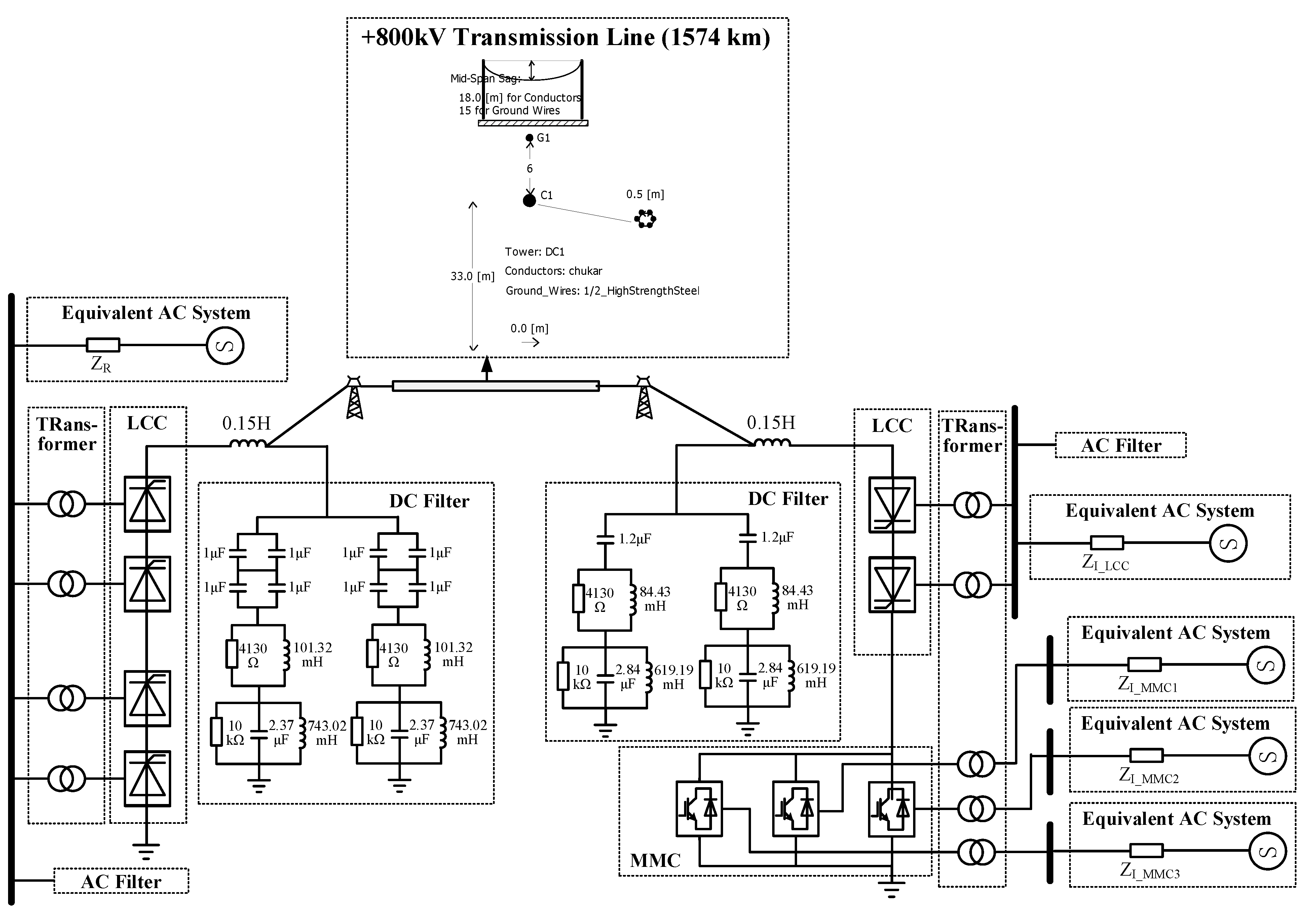
Figure 8 shows the diagram of the established model. The control strategy and primary parameters of the model come from the Baihetan–Jiangsu hybrid-cascaded UHVDC project in China. As can be seen from the figure, the backbone of the test network is a mono-polar 800 kV UHVDC link with 12-pulse LCCs on the rectifier side and a 12-pulse LCC in series with three parallel MMCs on the inverter side. The control system of converters is modeled in detail. The AC filters, the DC filters, and the smoothing reactors are also provided on both sides. The AC systems connected to converter stations are modeled by a voltage source in series with an impedance. The transmission line is modeled using the Frequency Dependent (Phase) model, which represents all the frequency-dependent effects of a transmission line.
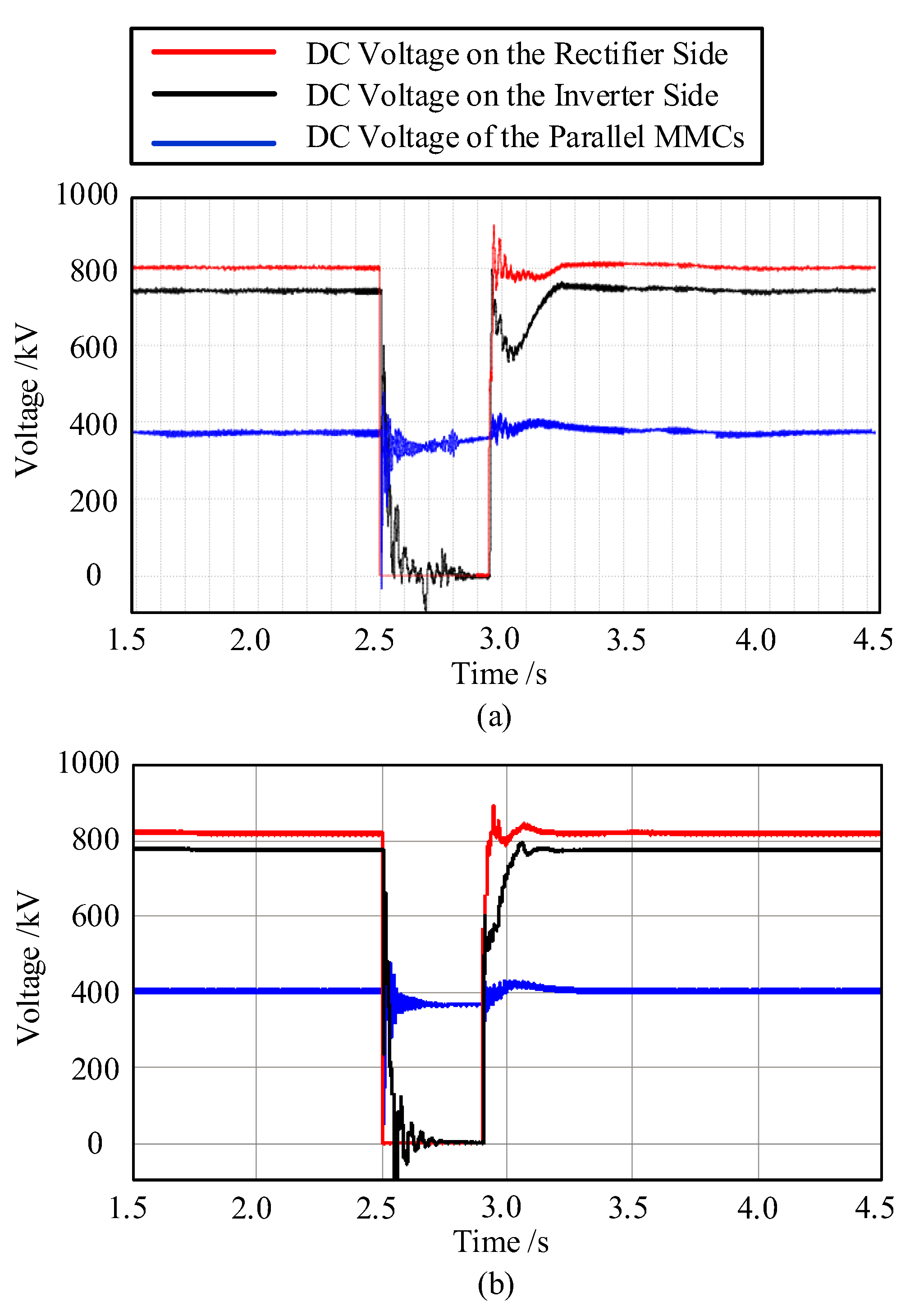
With the goal of verifying the effectiveness of the established model, the simulation results of this model are recorded and compared with the authoritative simulation results, which come from the model in the ADPSS (Advanced Digital Power System Simulator) Platform packaged by the China Electrical Power Research Institute. The comparison results under a DC line fault near the rectifier side are shown in
Figure 9. It can be seen that the DC voltage curves obtained by the two models are basically the same, proving the correctness of the modeled primary system and control strategy.
Based on the simulation model mentioned above, the effectiveness of the proposed power equalization control is further investigated. With the condition that the proposed strategy is utilized or not, the inverter active power responses are compared under faults applied at the rectifier side AC bus. The simulation results and discussions for symmetry and asymmetry faults are detailed as follows.
5.2. Symmetry Fault at the Rectifier Side
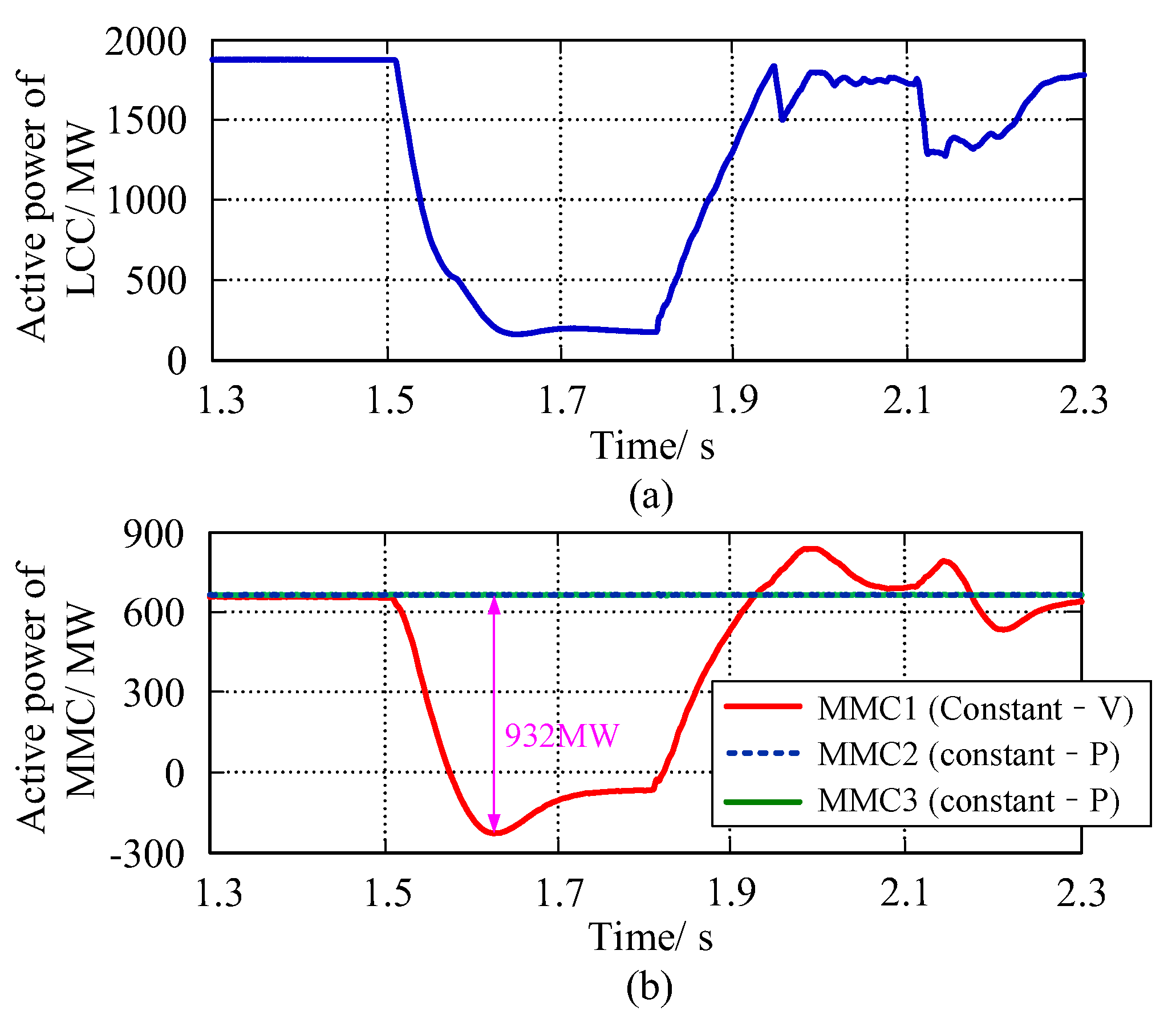
A three-phase grounding fault is applied at the rectifier side AC bus with a fault resistance of 5 Ω and fault duration of 300 ms. The active power flowing through the LCC and parallel MMCs during the fault period is measured when the proposed control is not used or used; the simulation results are shown in
Figure 10 and
Figure 11, respectively.
According to
Figure 10, under the dual functions of the current reduction on the DC side and direct current during the failure period, the active power of the high-end LCC at the inverter side dropped significantly, with a maximum decrease of over 1700 MW. For low-end MMC, since the voltage on the DC side remained unchanged, the reduction in power was lower than that of the LCC and equaled 932 MW. However, because no control logic for power equalization was added, the reduction in the active power of the MMC during the disturbance period was borne solely by MMC1 (with constant-voltage mode). The maximum unbalanced power among the MMCs was also 932 MW. It should be noted that the power of MMC1 during the disturbance period already dropped to negative, i.e., the MMC1 was in a rectifying state, and unnecessary mutual aid appeared among the low-end MMCs.
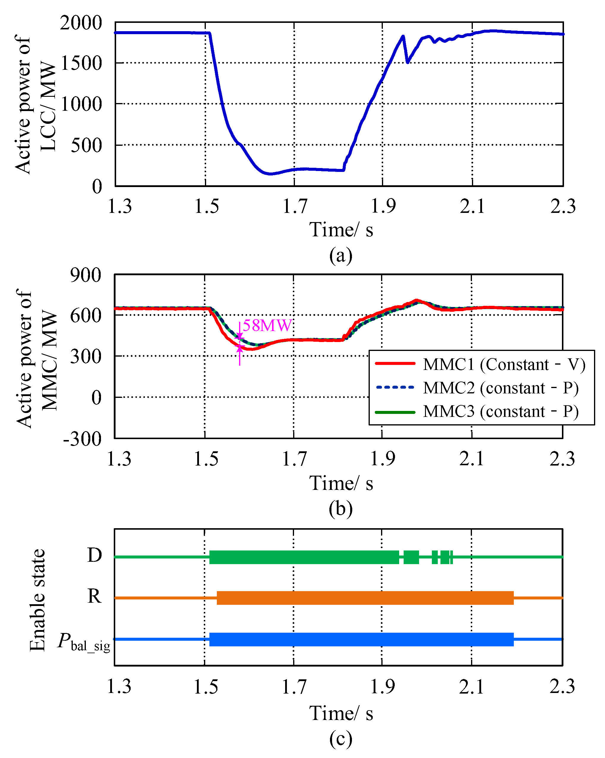
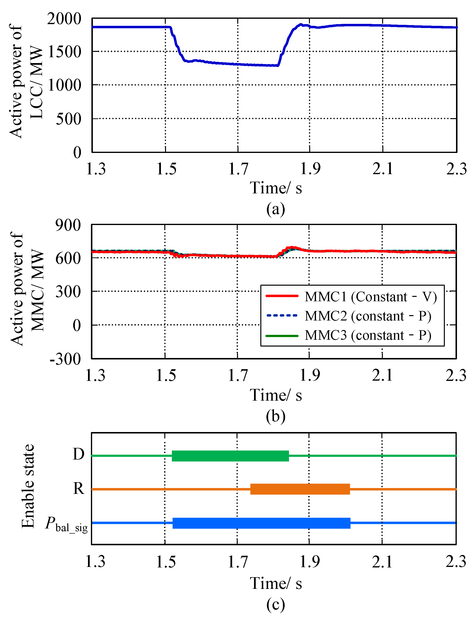
By comparing
Figure 10a and
Figure 11a, it is possible to conclude that the input of the proposed strategy had no effect on the falling amplitude of the power of the high-end LCC at the inverter side following a failure at the rectifier side. As shown in
Figure 11b, after the addition of the proposed strategy, MMC2 and MMC3 are able to rapidly trace the power-falling process of MMC1 following the occurrence of a failure and fill the overall power vacancy of the low-end valve groups. During the period between the occurrence of the failure and its recovery, the maximum decrease in active power among the three MMCs was 339 MW; meanwhile, the maximum unbalanced power decreased from 932 MW to 58 MW, allowing the AC system connected to MMC1 to avoid the impact of the failure at the rectifier side.
Figure 11c also demonstrates that the proposed control enabling logic can ensure rapid input after the detection of the LCC power falling and exit after both the LCC and MCC powers return to normal levels. In the meantime, using the proposed control logic, the frequent input/exit of control induced by the fluctuation of LCC power during the failure recovery period can be avoided.
5.3. Asymmetry Fault at the Rectifier Side
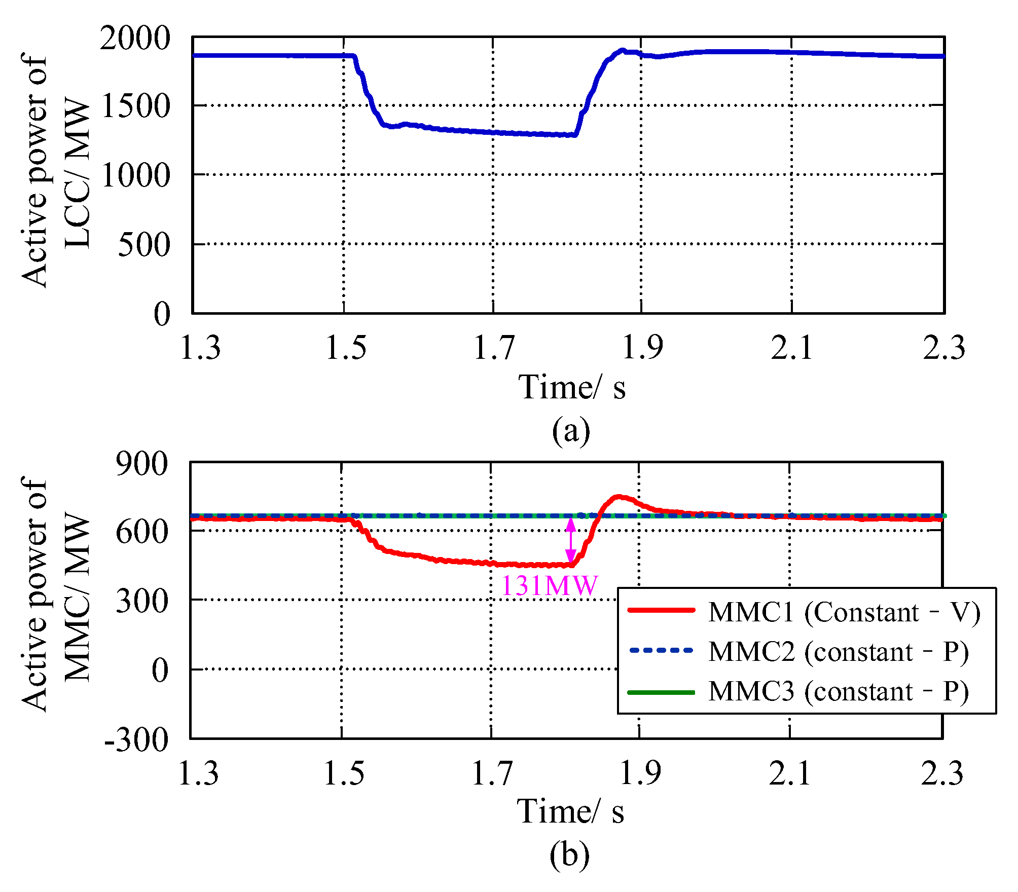
A single-phase grounding fault (A-G) is applied at the rectifier side AC bus with a fault resistance of 5 Ω and fault duration of 300 ms. The active power flowing through the LCC and parallel MMCs during the fault period is measured when the proposed control is not used or used; the simulation results are shown in
Figure 12 and
Figure 13, respectively.
In contrast to three-phase grounding, single-phase grounding can induce a less severe DC power disturbance under identical failure conditions. Comparing
Figure 12 and
Figure 13, the maximum power falling of the high-end LCC at the inverter side under the one-phase grounding condition at the rectifier side was approximately 500 MW; without the proposed control strategy, the maximum unbalanced power among three MCCs was 131 MW. Following the implementation of the proposed control strategy, the active powers of the three MCCs decreased slightly and simultaneously, and the imbalanced power can be ignored. Under the failure condition, the power equalization control module operated for a shorter time. In addition, since the total power decreased marginally, the power equalization performance can be enhanced.
6. Conclusions
This study investigated the control characteristics of a hybrid-cascaded UHVDC system. The power equalization control strategy for MMCs was proposed by analyzing the mechanism of unbalanced power among MMCs on the inverter side in the event of a failure on the rectifier side. In addition, the simulation was validated using the PSCAD/EMTDC platform.
The core of the proposed power equalization control strategy lies in the closed-loop control of the active power deviation between the constant-power MMC and the constant-voltage MMC. Consequently, all MMCs can share the low-end power vacancy on the inverter side equally in order to achieve dynamic power equalization. Meanwhile, the control enabling module was equipped to ensure that the control was only reliably input during the period of disturbance. The proposed strategy relied solely on the inverter’s state for control, with no communication between converter stations. The entire process of implementation is convenient.
Author Contributions
Methodology, L.L., Y.T. (Yufei Teng) and Y.T. (Yong Tang); Validation, L.L.; Formal analysis, X.L.; Investigation, X.J. All authors have read and agreed to the published version of the manuscript.
Funding
This research was funded in part by the Science and Technology Project of State Grid Sichuan Electric Power Company under Grant B3199722000K.
Data Availability Statement
Data is unavailable due to privacy.
Conflicts of Interest
The authors declare no conflict of interest.
References
- Shao, Y.; Tang, Y. Fast evaluation of commutation failure risk in multi-infeed HVDC systems. IEEE Trans. Power Syst. 2018, 33, 646–653. (In Chinese) [Google Scholar] [CrossRef]
- Sano, K.; Nakayama, H. A Fault Protection Method for Avoiding Overvoltage in Symmetrical Monopole HVDC Systems by Half-Bridge MMC. IEEE Access 2021, 9, 165219–165226. [Google Scholar] [CrossRef]
- Yang, X.; Lin, Z.; Zheng, Q.; You, X. A review of modular multilevel converters. Proc. CSEE 2013, 33, 1–15. (In Chinese) [Google Scholar]
- Jiang, G.; Li, Z.; Yang, H.; Yang, J. Research review on topological structure of flexible HVDC system. Power Syst. Prot. Control 2015, 43, 145–153. (In Chinese) [Google Scholar]
- Guo, C.; Liu, Y.; Zhao, C.; Wei, X.; Xu, W. Power component fault detection method and improved current order limiter control for commutation failure mitigation in HVDC. IEEE Trans. Power Deliv. 2015, 67, 1585–1593. [Google Scholar] [CrossRef]
- Wang, Y.; Zhao, W.; Yang, J.; Wang, N.; Lu, Y. Hybrid high-voltage direct current transmission technology and its development analysis. Autom. Electr. Power Syst. 2017, 41, 156–167. (In Chinese) [Google Scholar]
- Zhao, W.; Xuan, J.; Lu, Y.; Li, J.; Wang, Y. Research on circuit topology of hybrid HVDC system suitable for refurbishing existing LCC-HVDC. Electr. Power Autom. Equip. 2018, 38, 186–193. (In Chinese) [Google Scholar]
- Xu, Z.; Wang, S.; Zhang, Z.; Xu, Y.; Xiao, H. Inverter station connection modes and control strategies of LCC-MMC hybrid HVDC systems. Electr. Power Constr. 2018, 39, 115–122. (In Chinese) [Google Scholar]
- Liu, Z.; Ma, W.; Wang, S.; Zhong, Z.; Huang, Y. Schematic design of hybrid cascaded ultra HVDC and its modification in dynamic model experiment. Power Syst. Technol. 2021, 45, 1214–1222. (In Chinese) [Google Scholar]
- Liu, Z.; Wang, S.; Zhong, Y.; Huang, Y.; Guo, X. Controllable and adaptive energy absorption device for hybrid cascaded UHVDC transmission system. Proc. CSEE 2021, 41, 514–524. (In Chinese) [Google Scholar]
- Guo, C.; Zhao, C.; Peng, M.; Liu, Y. A hybrid HVDC system with DC fault ride-through capability. Proc. CSEE 2015, 35, 4345–4352. (In Chinese) [Google Scholar]
- Barnes, M.; Van Hertem, D.; Teeuwsen, S.P.; Callavik, M. HVDC Systems in Smart Grids. Proc. IEEE 2017, 105, 2082–2098. [Google Scholar] [CrossRef]
- He, J.; Tang, Y.; Zhang, J.; Guo, Q.; Yi, J.; Bu, G. Fast Calculation of Power Oscillation Peak Value on AC Tie-Line After HVDC Commutation Failure. IEEE Trans. Power Syst. 2015, 30, 2194–2195. [Google Scholar] [CrossRef]
- Liu, S.; Yu, J.; He, Z.; Liu, Z.; Guo, X. Research on the topology and characteristic of multi-terminal HVDC based on VSC and LCC. Proc. CSEE 2018, 38, 2980–2988+3148. (In Chinese) [Google Scholar]
- Yang, S.; Zheng, A.; Peng, Y.; Guo, C.; Zhao, C. DC fault characteristic analysis and recovery control strategy for hybrid cascaded HVDC system. Electr. Power Autom. Equip. 2019, 39, 166–172+179. (In Chinese) [Google Scholar]
- Dong, Z.; Wang, G.; Xu, Z.; Li, J.; Ding, H. Operation characteristic analysis method of Baihetan-Jiangsu hybrid cascaded UHVDC system. Electr. Power Autom. Equip. 2022, 42, 118–125. (In Chinese) [Google Scholar]
- Fan, X.; Guo, C.; Du, X.; Zhao, C. Reactive Power Coordinated Control Approach for Suppressing Subsequent Commutation Failure of Inverter Station in Hybrid Cascaded UHVDC System. Power Syst. Technol. 2021, 45, 3443–3452. (In Chinese) [Google Scholar]
- Guo, C.; Wu, Z.; Zhao, C. Balancing Control Strategy for Unbalanced Current Between Multiple MMC Converts in Hybrid Cascaded UHVDC System. Proc. CSEE 2020, 40, 6653–6662. (In Chinese) [Google Scholar]
- Huang, J.; Han, J.; Yang, T.; Li, S.; Chen, N. Voltage Distribution Strategy of Series Converters in Hybrid UHVDC Power Transmission System. South. Power Syst. Technol. 2021, 15, 71–79. (In Chinese) [Google Scholar]
- Wu, H.; Jiang, Q.; Li, B.; Liu, T.; Zhang, M. Fault current suppression method of multi-point hybrid cascaded DC system based on virtual impedance. Electr. Power Autom. Equip. 2023, 43, 191–196+202. (In Chinese) [Google Scholar]
- Wu, Z.; Guo, C.; Zhao, W.; Ye, Q.; Yang, S. Overcurrent suppression method for hybrid cascade UHVDC system based on fuzzy clustering and identification. Autom. Electr. Power Syst. 2021, 45, 131–139. (In Chinese) [Google Scholar]
- Faruque, M.O.; Zhang, Y.; Dinavahi, V. Detailed modeling of CIGRÉ HVDC benchmark system using PSCAD/EMTDC and PSB/SIMULINK. IEEE Trans. Power Deliv. 2006, 21, 378–387. [Google Scholar] [CrossRef]
- Xiao, H.; Li, Y.; Lan, T. Sending end AC faults can cause commutation failure in LCC-HVDC inverters. IEEE Trans. Power Deliv. 2020, 35, 2554–2557. [Google Scholar] [CrossRef]
- Son, H.; Kim, H. An algorithm for effective mitigation of commutation failure in high-voltage direct-current systems. IEEE Trans. Power Deliv. 2016, 31, 1437–1446. [Google Scholar] [CrossRef]
| Disclaimer/Publisher’s Note: The statements, opinions and data contained in all publications are solely those of the individual author(s) and contributor(s) and not of MDPI and/or the editor(s). MDPI and/or the editor(s) disclaim responsibility for any injury to people or property resulting from any ideas, methods, instructions or products referred to in the content. |
© 2023 by the authors. Licensee MDPI, Basel, Switzerland. This article is an open access article distributed under the terms and conditions of the Creative Commons Attribution (CC BY) license (https://creativecommons.org/licenses/by/4.0/).


