1. Introduction
The number of tunnels has been increasing year by year, with the mileage of road tunnels growing from 8522 km in 2011 to 23,268 km in 2021, and the total linear meters increasing from 6,253,000 m to 24,698,900 m. The compound growth rate is approximately 14.73 percent. Inspecting tunnels for quality purposes is a common practice to ensure construction quality and safety. Common tunnel safety problems include tunnel water leakage and lining cracking [
1]. Compared to surface problems of tunnels, their internal defects, such as holes, under-thickness, and antenna debonding, are not easily detected, verified, or managed, posing significant hazards during tunnel construction and operation. Internal problems with the tunnel lining structure have caused multiple accidents, such as the ceiling collapse in the Big Dig tunnel in Boston and the collapse of the Sasago tunnel in Tokyo [
2].
Compared to traditional inspection methods, NDT techniques provide greater advantages in detection, such as infrared thermography [
3], ultrasonic pulse [
4] and ground penetrating radar (GPR). Compared to traditional detection methods, GPR offers the advantages of high-precision, non-destructive, continuous, and rapid detection [
5]. Kuo-Chien Liao used thermal images of solar panels to detect various types of faults in solar modules. He combined mean filtering and median filtering techniques to create an innovative box filtering method [
6].
With the development and application of GPR, it is now possible to detect the internal structures and defects within tunnels, providing clear and accurate radar images. As a result, GPR has become an essential tool for tunnel inspection and detection, offering valuable insights into tunnel conditions and potential issues [
7]. The use of electrical parameters and geo-radar for cavity detection in water transmission tunnels by Holub in 1994 was the first study that traced the use of GPR in tunnels [
8]. Currently, GPR-based tunnel detection is also the most commonly used detection method. Kuloglu studied the effect of soil electrical conductivity and polarization scattering on geo-radar detection to investigate the role of ground-penetrating radar in tunnels [
9]. Zhang used nondestructive techniques, such as ground-penetrating radar, to investigate the effectiveness of post-lining grouting. The study demonstrated that GPR can be used to reduce the risk of long-term ground settlement [
10].
However, geological radar images are not direct images of the detected objects, and still require a large reserve of relevant knowledge in the interpretation of radar images, which strongly relies on the empirical judgment of data processing interpreters. In addition, the manual empirical interpretation of data is not only time-consuming and demanding, but the judgment is also highly subjective. In order to improve the speed and accuracy of geological radar interpretation, automatic detection will become an important means of infrastructure detection and will gradually become the trend of future development.
Automatic interpretation of ground-penetrating radar (GPR) has always been a hotspot and a challenge. However, the emergence of machine learning has partially addressed some of the shortcomings in manual interpretation and achieved automatic interpretation of GPR data. Pasolli [
11] and Xie [
12] employed genetic algorithms and support vector machine (SVM) algorithms for pattern recognition and classification of preprocessed GPR data, but obtaining the position and shape of gaps remains difficult. Dou used the C3 clustering algorithm to extract features from GPR reflection signals and fit them to hyperbolic curve parameters [
13].
Although machine learning can meet the basic requirements of automated interpretation, it still requires manual feature identification during model generation. For radar images, manual feature identification can potentially lower recognition accuracy. However, the advancement of deep learning has provided new solutions for GPR data processing and defect recognition. Deep learning has emerged as a popular approach for automatic recognition of radar images, as it eliminates the need for manual feature identification and allows the model to learn complex patterns and representations directly from the data.
Convolutional neural networks (CNN) can achieve high interpretation accuracy, reduce the workload of manual recognition, and reduce labor costs [
14]. Zhang first applied the deep learning algorithm convolutional neural network to road crack detection, and proved that the convolutional neural network can still get good recognition effect for the photos of cracks with serious noise according to the experiment [
15]. Combining GPR data processing, pattern recognition and neural network, Nuaimy successfully realized the labeling, imaging and classification of GPR data [
16]. Xiang used AlexNet and GPR images to automatically detect knotted steel arches in images. The effect of different steel arch arrangements and window sizes on the results was also evaluated [
17]. Alvarez used a deep learning framework to convert GPR images into subsurface 34 dielectric constant maps for visualization of subsurface images of sewer tops [
18]. W. Li proposed WearNet for scratch detection, and its application in embedded systems exhibits the advantages of a small model size and fast detection speed [
19].
Table 1 shows the recent summary of papers, indicating whether deep learning algorithms were used and specifying the names of the algorithms employed. This clearly demonstrates that deep learning algorithms have become the mainstream approach in radar image detection.
With the advancement of deep learning, more advanced models are excelling in tunnel interior detection. In the field of deep learning, radar image detection involves object detection, which can achieve recognition and localization of selected targets [
23]. Deep-learning-based object detection methods can be divided into two categories: region selection and regression.
The region boxing selection class is mainly composed of R-CNN [
24], Fast-RCNN [
25], Faster-R-CNN [
26] and Mask-R-CNN [
27]. The region box selection class of methods is highly accurate, but greatly reduces the detection speed. Feng used two target detection algorithms, Faster R-CNN and YOLOv3, to achieve automatic recognition of radar images of tunnel lining, and the recognition effect of the two algorithms was compared, which proved that the two algorithms can form complementary in identifying steel arches, steel arch networks, and construction joints [
28].
In comparison, regression-based methods have an advantage in terms of detection speed. They can directly obtain the position and class information of the targets without the need for region proposal generation. The main regression-based methods include YOLO [
29], SSD [
30], and CenterNet [
31]. YOLO is one of the more advanced one-stage detection methods, which includes YOLOv3 [
32], YOLOv4 [
33], YOLOv5 [
34], and YOLOX [
35], among others.
Pham et al. improved YOLO by proposing the YOLO-fine model for detecting GPR images in aviation and satellite applications, with a focus on smaller objects [
20]. In GPR images, our attention is primarily on hyperbolic curve features, and this method does not address irregular features. Li et al. used YOLOv3 as the base model and employed the K-means algorithm to improve the accuracy of hyperbolic vertex localization. They also used VioU to reduce false detection boxes and improve recognition accuracy [
21]. However, their recognition primarily focuses on hyperbolic curve signals displayed by objects in GPR, whereas objects or cracks in GPR images may not always appear as hyperbolic curve signals, and they did not address the recognition of other types of features.
Junlong Tang improved the analysis capability of the YOLOv5 model by replacing the backbone network with Swin Transformer, reducing the interference between the background and image defects. He proposed the PCB-YOLO model, which solves problems associated with the low accuracy and slow speed of defect detection in printed circuit boards [
22]. Zhen Liu combined YOLOv5 and GPR to achieve rapid identification of road defects [
36].
Table 2 summarizes other researchers’ relevant methods and their key points in defect identification.
The existing method has a high correct rate for detecting static and individual similar objects such as steel arches in radar images, but has room to improve the recognition rate for the hole types with different sizes and shapes. In addition, there are more interfering factors in radar images, and the correct rate of the model for detecting the interfered object images decreases. For the problems of secondary lining internal hole and steel arch recognition, this paper proposes an attention fusion algorithm based on YOLOX, which combines its backbone with Swin Transformer and incorporates attention mechanisms. The YOLOX algorithm is used as the base algorithm, and its backbone is fused with Swin Transformer to enhance the model’s multi-scale feature extraction capability. This allows the model to preserve more information in extracting local and global features, thereby improving the feature extraction for hyperbolic signals and irregular gaps. The CBAM attention mechanism is introduced, which focuses the model more on the detected objects through its channel attention and spatial attention mechanisms, thereby increasing the detection accuracy for small-scale gaps. Based on this, real-world collected data are used as the dataset for training and validation, achieving high accuracy and strong generalization capability for radar image detection.
Table 2.
Key points of each study in the literature review.
Table 2.
Key points of each study in the literature review.
| References | Key Point |
|---|
| Xiang [17] | Use AlexNet to automatically detect steel arch frames in images and evaluate the impact of steel
arch frame arrangements and window sizes. |
| Alvarez [18] | Convert the GPR image into a subsurface permittivity map and display the subsurface image
of the sewer top. |
| Pham [20] | It has been proposed to use the YOLO-fine model for detecting GPR images in aerial and satellite
imagery. |
| Li [21] | Using the K-means algorithm to improve the accuracy of hyperbolic vertex localization and
identify hyperbolic signals displayed GPR. |
| Junlong Tang [22] | The PCB-YOLO model has been proposed, which replaces the backbone network in the YOLOv5
model with the Swin Transformer. This addresses the issues of low accuracy and
slow speed in PCB defect detection. |
The main work reported in this paper includes the processing and preparation of the data, the selection and analysis of the neural network, the comparison of the radar image recognition performance, and the application to real data. In
Section 2, our improved model is presented, with a description of the components of the improved model. In
Section 3, the specific parameters of the experiments using neural networks are presented, and the performance of the proposed improved model is discussed, comparing it with other models.
Section 4 reports the analysis of the results of the application of the measured data. Finally, in the concluding section, we summarize the contributions of this paper.
2. Materials and Methods
2.1. YOLOX Network Model
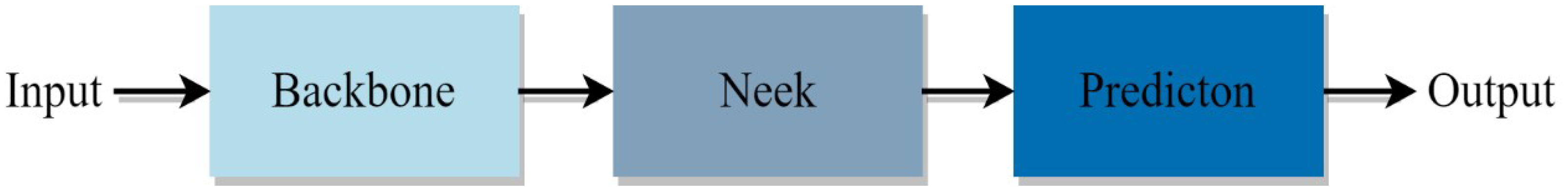
YOLOX is an object detection network from the Megvii Research Institute (Beijing China) (formerly known as Megvii Technology), which is based on the YOLO series. It builds upon the YOLOv3 model by incorporating enhancements such as data augmentation, decoupled prediction heads, and anchor-free improvements. YOLOX, based on the darknet53 backbone, improves the best performance on the COCO dataset from 44.3% AP achieved by YOLOv3 to 47.3% AP. The main structure of YOLOX is shown in
Figure 1.
2.2. Backbone
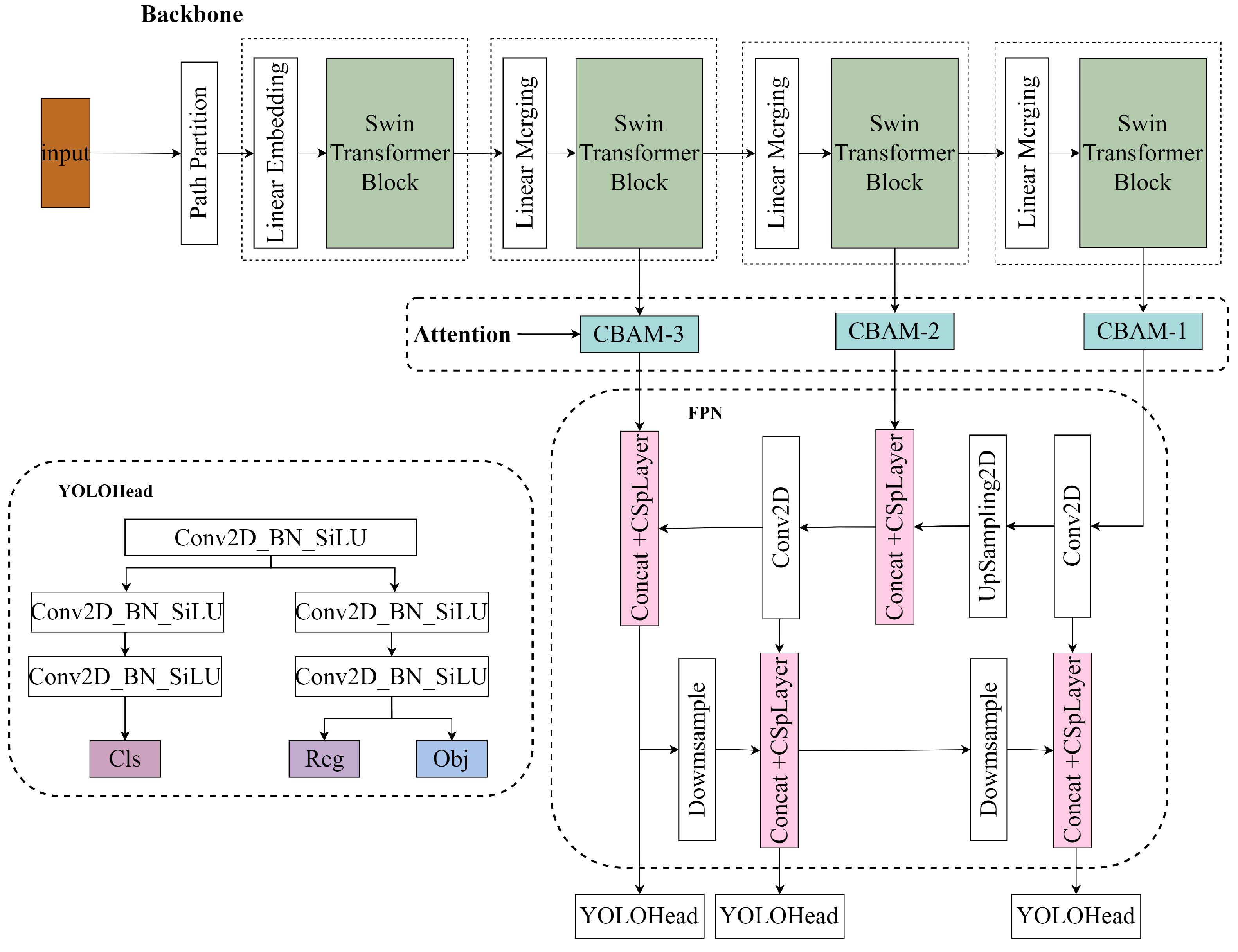
As shown in
Figure 2, the tunnel radar detection model consists of three main components, and the work done by the network is feature extraction—feature enhancement—prediction of objects corresponding to the feature points.
The original backbone of YOLOX is CSPNet, which stands for Cross Stage Partial Network. By incorporating the CSP structure, CSPNet addresses the issue of redundant information in the backbone network, particularly in the gradient optimization process of large-scale neural networks [
37]. This significantly reduces the number of model parameters and floating-point operations (FLOPs), thereby improving the inference speed of the final model. The block-based structure allows CSPNet to excel in extracting local features. Swin Transformer enables hierarchical feature extraction in transformers, allowing extracted features to possess a multi-scale concept and introducing interactions between adjacent windows through the shift operation [
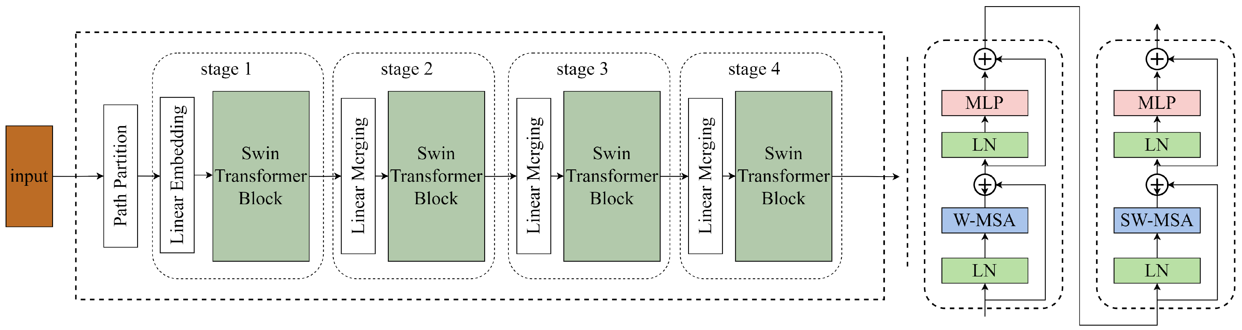
38]. Parts with similar semantics are more likely to appear in neighboring regions, combining the advantages of window sliding, similar to convolution, with the ability to capture global contexts. It is precisely the window sliding mechanism that empowers Swin Transformer to achieve better performance in global feature extraction. The main structure of Swin Transformer is shown in
Figure 3.
Swin Transformer enables hierarchical feature extraction in transformers, allowing extracted features to possess a multi-scale concept and introducing interactions between adjacent windows through the shift operation. Parts with similar semantics are more likely to appear in neighboring regions, combining the advantages of window sliding, similar to convolution, with the ability to capture global contexts. It is precisely the window sliding mechanism that empowers Swin Transformer to achieve better performance in global feature extraction.
The proposed backbone combines Swin Transformer with CSPnet as the main component. It extracts three effective layers (stage 2–stage 4) from the Swin Transformer structure and combines the Transformer Block from
Figure 3 with the patch merging in the effective layers. This extracted network structure serves as the main backbone of the improved radar image detection model. The three extracted effective feature layers correspond to downsampling ratios of 8×, 16×, and 32×, respectively. These correspond to the input downsampling layers of CSPDarknet53 in YOLOX, which are the outputs of the backbone in the YOLOX structure. The patch merging is similar to the focus structure in YOLOX’s CSPDarknet53, where independent feature layers are stacked, concentrating the width and height information into the channel information. This results in an expansion of input channels, enhancing the information extraction process.
Swin Transformer significantly improves the computational efficiency of self-attention mechanisms while addressing the limitations of lacking global image perception and macro understanding [
39]. It integrates multiple streams of semantic information and, when combined with the original CSPDarknet53, allows the model to extract both local and global feature information effectively, preserving global and local features to the maximum extent. This combination demonstrates significant improvements in detecting small and irregular object categories such as radar images.
2.3. Attention Mechanism
The attention mechanism allows the model to focus more on the parts of the network that are of greater interest for small target detection in the detection of radar images, thus improving the correct rate of the model for small target detection and recognition. The attention mechanism used is a hybrid domain attention mechanism convolutional block attention module (CBAM) [
40]. The CBAM module consists of a channel attention module and a spatial attention module, which generate the corresponding weights in both channel and spatial dimensions during the detection of radar images, and add the attention mechanism to the output image of the FPN pyramid, using the attention mechanism for each output image. CBAM contains two modules, the channel attention module and the spatial attention module, both of which use the channel and spatial attention mechanisms for images, respectively. This not only saves parameters and computational power, but also makes it more concise and allows for better integration into existing network structures.
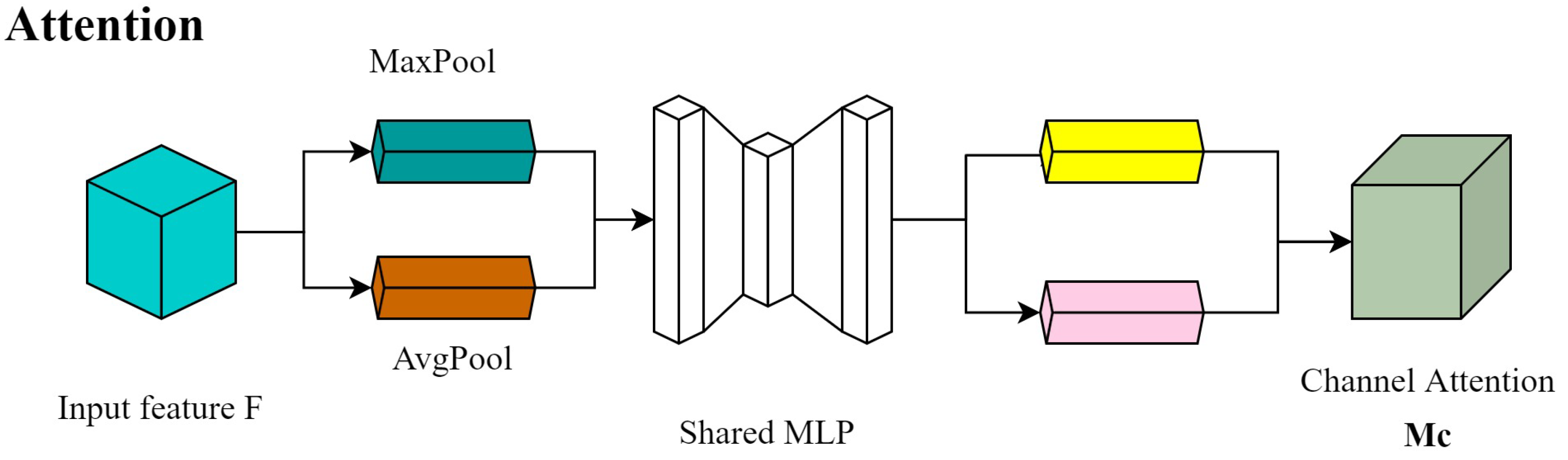
2.3.1. Channel Attention Module
Each input feature map F is fed into the CBAM, which is first fed into the attention module of the channel, where the feature map is subjected to global maximum pooling and global average pooling operations to obtain a one-dimensional vector feature map, and then fed into a two-layer convolutional neural network (MLP). The output of MLP processing is multiplied with the feature map F to generate the channel weight feature Mc, which is used as the input of the spatial attention module. The structure is shown in
Figure 4.
2.3.2. Spatial Attention Module
The feature Mc output from the channel attention mechanism is used as input, and after global maximum pooling and one global average pooling operation, the spatial dimension is obtained by a channel stitching and then convolution operation for spatial dimension calculation Ms (F). The structure is shown in
Figure 5.
2.4. FPN and YOLOHead
After the backbone network’s convolutional feature extraction, the Feature Pyramid Network (FPN) [
41] is employed to enhance the feature extraction process. In radar images, small-scale gaps often occur. By fusing different scale feature maps, the previously down-sampled feature maps that may have lost some details during convolutional processing can be combined with the feature maps obtained after the final convolutional operations. This allows for the preservation of fine-grained details in the images and integrates the final semantic features, which contributes to effective feature extraction for small objects in radar images. As a result, it achieves improved recognition performance for small-scale holes in radar images.
YOLOhead is responsible for the classification and regression of images after feature extraction by CSPdarknet and enhancement of features by FPN, and for the prediction of images in the whole radar image detection model. The decoupling head used in previous versions of YOLO was together, i.e., classification and regression were implemented in a 1 × 1 convolution, which YOLOX believes has a detrimental effect on the recognition of the network. In YOLOX, the Yolo Head is divided into two parts, implemented separately, and only integrated together for the final prediction.
2.5. Dataset Production and Enhancement
Representing a segment of distance within a tunnel. However, when training a model, there are limitations on image sizes. If the original-sized images are directly used, the model will perform a resize operation, forcing the images to conform to the model’s specified size. This operation can alter the shape of objects in the image, potentially affecting the recognition accuracy of the model.
When processing radar images, the scarcity of certain samples, such as void regions, leads to a limited amount of available training data. Directly segmenting the images would result in each sample information being used only once. To overcome this issue, a solution is to adopt a sliding window approach, capturing image patches at regular intervals.
By using the sliding window approach, the model’s size requirements can be met, and the number of training images can be increased. Additionally, in
Figure 6, this approach ensures that the required sample information appears in both the left and right positions of the image, enhancing the diversity of samples. This method allows for better utilization of limited training data, leading to improved model generalization capabilities.
After segmenting the images, you can use the labelImg tool to annotate the captured images. Use rectangular bounding boxes to select the steel arches and void regions in the images, and store the corresponding label information in an XML file. The label information typically includes the image name, the category corresponding to each label, and the size and position information of the label in the image. The position information is determined by the x and y coordinates in the XML file, as shown in
Figure 7. During the final image prediction, you can also refer to the labels to understand the size and position information of the samples.
To enhance the data, two techniques, Mosaic and Mixup, are employed. The Mosaic technique involves randomly selecting four images, scaling, cropping, and arranging them together. This approach significantly improves the detection performance for small objects. On the other hand, Mixup is a method of augmenting the dataset through random blending. This technique enriches the background of tunnel radar images and introduces scenarios where multiple categories are closely adjacent to each other. By using Mixup, the dataset becomes more diverse, which can benefit the training and generalization of the model.
In practical radar imaging, noise interference can be present due to detection operations or interference from other objects within the detected target. In this experiment, noise removal methods were employed to mitigate the effects of noise interference. The main methods used for noise removal include removing direct ground waves and removing high and low-frequency signals. These techniques aim to reduce the noise in the radar images and improve the overall quality and accuracy of the data.
2.6. CIOU
The algorithm divides the images into s × s grids, and each grid predicts m boxes. It also analyzes whether there are targets among the grids and the classes of the targets. YOLOX uses a non-maximum suppression method to calculate the score of each preselected box and selects the highest scoring preselected box to calculate IoU (Intersectionover Union). A is the predicted box and b is the real box [
42]. IoU is the ratio of the intersection of two boxes to the area of the concatenated set.
By simultaneously setting an IoU (Intersection over Union) threshold, pre-selected boxes with an IoU value below the threshold are suppressed and discarded. The remaining pre-selected boxes are then evaluated. Through iterative adjustment of the IoU threshold, the final set of pre-selected boxes ensures that there is no overlap among them.
IoU is a concept based on ratios and is insensitive to the scale of the target object. When calculating the bounding box (BBox) regression loss function for optimization, there are multiple optimization approaches. CIOU (Complete Intersection over Union) addresses the issue where the general IoU cannot directly optimize the non-overlapping parts of two boxes [
43].
CIOU takes into account the overlapping area, the enclosing area, and the distance between the centers of the boxes to calculate a more comprehensive similarity metric. By considering these factors, CIOU provides a more accurate measure of the similarity between bounding boxes and can be used as an objective function for optimization. It allows for better optimization of bounding box predictions, especially in cases where the boxes have no overlap.shown in
Figure 8.
CIOU takes into account the distance between the target and anchor boxes, overlap ratio, scale, and a penalty term. By considering these factors, CIOU provides a more stable regression for the target boxes compared to IoU and GIoU. It avoids issues such as divergence during the training process.
where
is a positive trade-off parameter, and
v measures the consistency of aspect ratio.
,
are the width and height of B, respectively.
w,
h are the width and height of A, respectively. Additionally, the penalty factor in CIOU takes into account the aspect ratio of the predicted box and aligns it with the aspect ratio of the target box. This ensures that the predicted box’s aspect ratio is closer to the target box’s aspect ratio, leading to improved accuracy and stability in the regression process. Overall, CIOU enhances the performance of bounding box regression by considering multiple factors and incorporating a penalty term.
2.7. Training Results and Analysis
The network has a relatively large number of parameters, but a small dataset. To avoid overfitting phenomena, migration learning is used to train the model, which is especially important for small datasets. The COCO dataset consists of more than 500,000 image data points with 80 different classes. The model uses the weights in the COCO dataset as pre-trained weights [
44].
In terms of data augmentation, Mosaic combines four images as a group and randomly scales, crops, and arranges them together. This approach greatly improves the detection performance for small objects. On the other hand, Mixup increases the dataset by randomly blending different images. This method enriches the background of tunnel radar images and introduces scenarios where multiple categories are close to each other.
This dataset consists of 2000 tunnel radar images, with a training set and a test set in the ratio of 8:2. In the training process, Mosaic and Mixup data enhancement are turned on, and SDG optimizer is selected. The random gradient descent of SDG will make the loss function fluctuate, so a larger learning rate and the number of training rounds should be set. The learning rate is set to , while the minimum learning rate is 1% of the set learning rate and the weight decay is . 8 images are set as a group for each training, and a total of 100 rounds are trained. Mixed precision training is used to reduce the requirement for graphics card configuration.
Target detection generally selects mean Average Precision (
) and Average Precision (
) as experimental evaluation metrics.
and
need to be calculated based on the Precision and Recall of the model training samples, which are calculated as follows.
where
denotes the positive samples detected correctly,
denotes the negative samples detected incorrectly, and
denotes the positive samples detected incorrectly. And the average accuracy
is obtained from the area enclosed by the
curve and the coordinate axis, which is calculated as follows.
where
denotes the
i+1st recall value,
P is the precision,
n is the number of sample categories, and
i denotes the current number. The average precision mean
is then the mean of all categories
, which can be expressed as:
where
denotes the
i-th average precision and
K denotes the category to be classified.
The loss value represents the difference between the prediction result and the real label, and the reduction of the loss value also means that the training effect is improved. At the same time, high also indicates good performance of the trained model.
Calculating the loss refers to the comparison between the predicted result of the network and the real result of the network. The loss function of YOLOX is shown in Equation. Where the output side predicts three branches, respectively, the
part, the
part, and the
part.
where
represents classification loss,
represents regression loss,
represents object loss
represents the balance coefficient of localization loss, which is set to 5.0 in the source code;
represents the number of Anchor Points that are classified as positive samples.
part is the regression parameter judgment of feature points,
part is the judgment of whether the feature points contain objects, and
part is the kind of objects contained in the feature points. For regression loss
, YOLOX replaces the mean squared error function with the
function. For object loss
and classification
, YOLOX algorithm uses binary cross-entropy loss instead of cross-entropy loss. The binary cross-entropy loss function is shown below.
3. Results and Discussion
After sending the test dataset to the trained object detection model, the results with different threshold values are compared. The comparison of YOLOX before and after improvements is shown in the
Table 3.
Based on the table, it can be observed that adding CBAM and improving the model both result in improvements in % values. The addition of CBAM and the improved backbone, compared to YOLOX-s, leads to a 5.2% increase in %, a 4.5% increase in precision (P), and a 4.4% increase in recall (R). YOLOX-s + CBAM, with the inclusion of three CBAM modules, increases the model size by 219 kb. On the other hand, the improved model incorporates Swin Transformer and increases the model size by 5207 kb. Additionally, the inference time also increases by 1.46 ms and 4.09 ms, respectively.
It can be seen that Improved YOLOX, compared to the original model, slightly increases the parameter size and recognition time, but the recognition time remains within an acceptable range. However, it significantly improves the mAP% value, demonstrating the superiority of Improved YOLOX.
Table 3.
Ablation Study of models.
Table 3.
Ablation Study of models.
| Model | P | R | mAP% | Inference Time/ms | Weights/MB |
|---|
| YOLOX-s | 86 | 87 | 89.1 | 14.26 | 35,110 |
| YOLOX-s + cbam | 89.2 | 90.5 | 91.5 | 15.72 | 35,329 |
| Improved YOLOX | 90.5 | 91.4 | 94.3 | 17.35 | 40,536 |
3.1. Loss
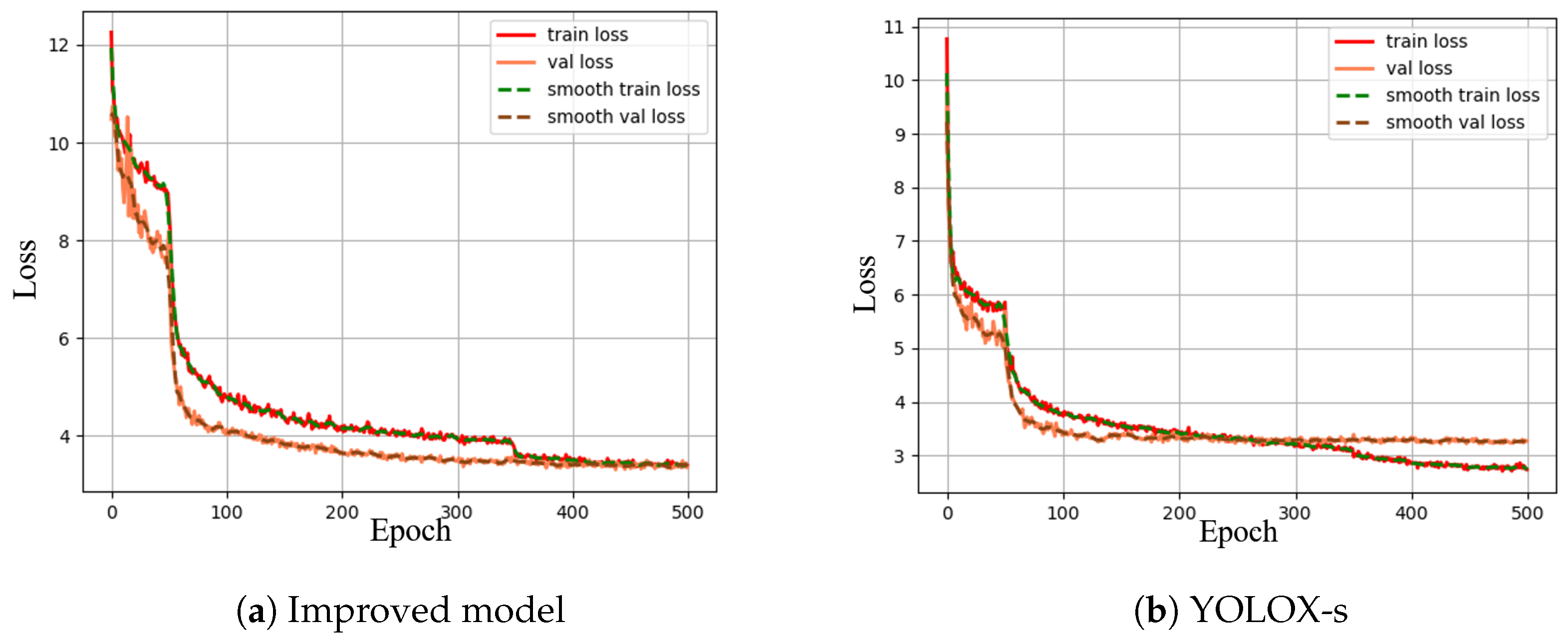
The loss value can effectively determine the convergence of the model and infer the degree of learning of the model on the radar image dataset and the learning rate based on the convergence. The training set loss and validation set loss of the improved radar detection model type in the training process are plotted in the curves shown in
Figure 9. From the data in the figure, the trends of the training set loss and validation set loss during the training of the improved model are basically the same, with the increase in the number of training rounds, the recognition correct rate of the holes and steel arch is also gradually rising and nearly flat, and the model gradually converges; the loss of the model decreases faster in the first 70 times of training, and the model backbone thaws in the 51st time, which leads to a sudden decrease in loss, and the model gradually approaches the optimal point after 100 times of training The loss decreases slowly and converges at about 320 training cycles, i.e., it has reached the optimal point.
The left figure shows the improved radar image detection model, and the right figure shows the original YOLOX-s without any improvement, the loss value of the improved image detection model converges more rapidly, and the improved radar image detection model has a higher correct rate and lower loss than the improved model for both labels under the same parameters, the loss of the improved model before and after the improvement converges to 3.45 and The loss of the improved model converges to about 3.45 and 2.70, respectively, which proves that the improved strategy and parameter settings proposed in this paper are reasonable and effective in improving the recognition accuracy of the model.
3.2. mAP Values
Figure 10 shows the comparison between the improved radar image detection model and the ordinary YOLOX model of
value, respectively.
value in improved model gradually increases with the number of training rounds and eventually level off.
value rises rapidly in the early training period until about 200 rounds when it starts to level off and the convergence rate decreases. In the first 50 rounds of the backbone freezing part, the convergence trend is more choppy and rises slowly, while after 50 rounds the backbone network is thawed out and starts to rise smoothly and sharply. The highest value of 94.2% is finally reached basically at 300 rounds, meaning it has reached the optimal point.
Comparing the two models, the value of the radar image detection model rises more rapidly than that of the unimproved YOLOX-s model. Additionally, the value is higher at convergence, and the improved model has a higher correct rate of recognition for both labels in the radar image, where the before and after improvement is 94.2%. This proves that the model improvement makes the detection correct rate higher and more suitable for processing radar. It is proved that the model improvement makes the detection correct rate higher and more suitable for processing radar images.
3.3. Comparison of Different Models
Table 4 summarizes all the training results of the model. It is obvious that the higher the weights, the higher the evaluation metrics.
The Faster-RCNN, YOLOX-l, YOLOX-s, YOLOX-s + se, YOLOX-s + eca and the improved models were compared in terms of value and prediction time, respectively. The value of the improved model is higher than the other models, i.e., the detection accuracy is better than the other models. Comparing the improved model with YOLOX-s + se, both are higher in recognition accuracy, but the improved model is better for steel arch tag recognition, indicating that the improved model has more advantages for small target recognition. YOLOX-s is the model with the smallest volume model and the fastest detection speed in the YOLOX series.
On which the improvement improves the
value by 6.51%. In summary, it can be demonstrated that the improved model offers superior performance by balancing speed and accuracy. The data in
Table 1 show that most of the recognition models have higher AP values for “steel arch” tags than for “holes” tags. This indicates that most of the models have better recognition results for fixed style tags.
Using the improved model and YOLOX-s for the recognition of the two categories “Rebar” and “holes”, select some recognition results to shown in
Figure 11,
Figure 12 and
Figure 13.
Comparing
Figure 11, the YOLOX-s model has a lower confidence level for the identification of the debris problem, but the location of the confidence box can frame a larger range of debris information, and the identification is not accurate enough, and the phenomenon of repeated frame selection occurs. The steel arch at the edge of the image is also not identified by YOLOX-s, while the improved model has 78% correct recognition rate for the steel arch at the edge of the image. In
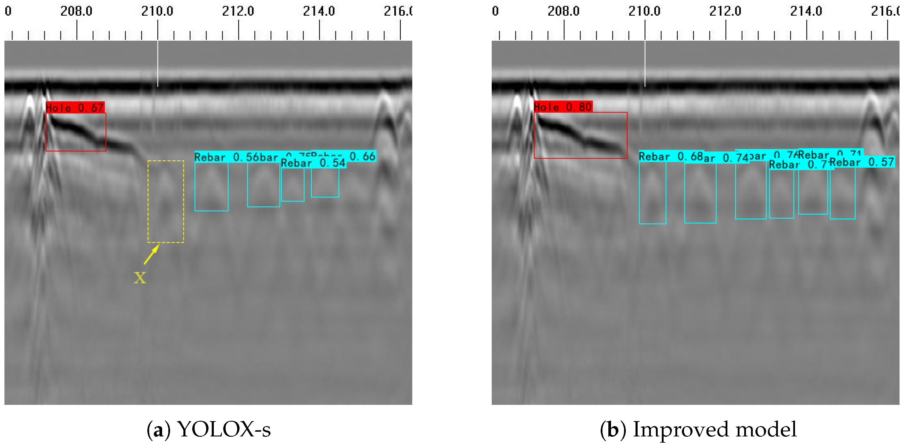
Figure 12, only the more obvious part of the hole is recognized, but not the whole hole, and the steel arch at x is closer to the hole, making the two images closer, and YOLOX-s does not recognize it. The improved model uses Transformer as the main structure of the network, which has a better effect on the recognition of steel arches in complex scenes, and can recognize the steel arches here with 83% correct recognition rate.
Only one category of steel arch exists in
Figure 13, but the steel arch signal at the Z position on the right side of the image near the edge of the image. the Z position signal is not completely shown in the image and is not identified as a steel arch signal. According to the magnified image, the steel arch signal is more sharp due to the steel arch being squeezed by both sides, and the upper part of shows a larger area of white image, while the black image of the steel arch body position is missing, rendering the recognition effect poor. The improved attention mechanism of the model enables the model to pay closer attention to small targets, and can also compensate for the problem that YOLOX-s does not have a high correct rate of small target recognition for steel arch targets that are close to the edges in the c-image and contain large differences between the images and the training set data.
Apart from identifying steel arches and voids in simple plain concrete backgrounds in
Figure 14, the more common scenario would be in reinforced concrete backgrounds. GPR images of reinforced concrete are more complex and have more interference factors, making the identification process more challenging. However, even in such cases, an improved model can still accurately recognize them. In the case of slight voids in steel arches, their representation still appears as hyperbolic curves, and the voids are located closely to the arches, which makes them less distinct. The improved model’s backbone can better extract global features and capture the overall information of the voids, enabling their identification. In the detection of concrete structural elements, we tested 181 hyperbolic curves in GPR images. The model correctly detected them 162 times, with 12 instances of missed detection and 8 instances of false alarms. Overall, the performance of the improved model in recognizing and locating steel arches and voids from GPR image features is satisfactory.
Upon comprehensive diagram observation, it can be found that the steel arch recognition effect is higher than the hole. In the tunnels, the debris situation is more complex and irregular, resulting in excessively small or large cases in the recognition of omissions and misjudgments. The current dataset contains 800 images, which is not suitable for some extreme cases. However, the model can achieve higher correct and recall rates for small target cases, such as the “steel arch” category. Because steel arches are represented more singularly in the image, the occurrence type is not complicated, and the improved model has better accuracy for small target detection.
4. Discussion
In this paper, a more accurate geological radar image detection algorithm for the interior of tunnels was achieved by improving the YOLOX model. The algorithm enables precise recognition of two objects inside the tunnel: “void” and “steel arches”. Additionally, a comparison and experimentation of different models were conducted under equivalent conditions, and an analysis was performed on real radar image data.
Under a simple plain concrete background, the original model can achieve substantial recognition of steel arches and voids. However, the recognition performance drops significantly when hyperbolic signals are not fully displayed at the image borders or where they connect to voids. On the other hand, the improved model can accurately identify samples with interferences and can generally recognize all labels across the plain concrete background.
In practical situations, we mostly encounter recognition tasks with a reinforced concrete background. The improved model also yields satisfactory recognition results in reinforced concrete scenarios. However, when both voids and steel arches coexist in the image, and the voids are closely adjacent to the steel arches, resulting in only hyperbolic signals of steel arches dominating the radar image, the recognition of voids becomes incomplete. Nonetheless, in the experiments, the improved model achieved a confidence level of over 80% for label recognition, meeting the engineering standards.
Data processing is crucial during the experiments. Due to device or complex site interferences during tunnel radar image collection, the presence of noise is unavoidable. The denoising method used in this study can only reduce the occurrence of noise. If additional denoising methods are applied during the experiments, the model’s image recognition accuracy is expected to further increase.
The input section of the experiment is subject to size restrictions, where the images need to be resized to a specified dimension of 320 px × 320 px during training. If the images are too large or too small, the model will forcibly resize them to fit the required size, leading to the loss of original image features and resulting in unsatisfactory experimental results. In future experiments, we will attempt to optimize the resizing module of the model to remove this input limitation.


