Article

A Hierarchical Energy Control Strategy for Hybrid Electric Vehicle with Fuel Cell/Battery/Ultracapacitor Combining Fuzzy Controller and Status Regulator

College of Mechanical and Electrical Engineering, Shihezi University, Shihezi 832003, China
*
Author to whom correspondence should be addressed.
Electronics 2023, 12(16), 3428; https://doi.org/10.3390/electronics12163428
Submission received: 24 July 2023 / Revised: 7 August 2023 / Accepted: 9 August 2023 / Published: 14 August 2023

Abstract

:
In order to improve the fuel economy of fuel cell hybrid electric vehicles (FCHEV), a hierarchical energy management strategy (HEMS) is proposed to rationally allocate the required power to a hybrid power system with three energy sources: fuel cell, battery, and ultracapacitor. First of all, batteries and ultracapacitors are regarded as energy storage systems (ESS), which convert the distribution problem from three energy sources to two couples of energy sources. Secondly, fuzzy logic controllers are utilized in upper-layer energy management strategies (EMS) to distribute required power to fuel cell systems and the ESS. To extend the service life of the fuel cell and increase the maintenance ability of the state of charge (SOC) of the battery, a status regulation module is introduced to allocate the required power combined with fuzzy controller. Thirdly, an adaptive low-pass filter is applied to a lower-layer EMS based on the energy characteristics of the ultracapacitor, which fully utilizes the ultracapacitor. Finally, the economic and dynamic performance of the vehicle are compared between the HEMS and the power following strategy (PFS) under five typical cycle conditions: UDDS, WVUINTER, NEDC, HWFET and COMBINE. The results of the simulation show that the hydrogen consumption of the HEMS is reduced and the overall vehicle energy efficiency is increased in four operating conditions, which indicates that the proposed strategy has better economic performance. In addition, the dynamic performance of the vehicle is also improved.

1. Introduction

To meet the growing demands of global consumers and response to national calls for reductions in fossil fuel consumption and harmful emissions, the primary target of the automotive industry is to replace fossil-fueled internal combustion engine vehicles with a clean, sustainable energy alternative [1]. Hydrogen is one type of clean energy, and the product of its oxidation is only water when hydrogen is utilized as the fuel, contributing to the world’s environmental protection. Hence, hydrogen fuel cells have become the object of research by the automobile industry and a large number of academics [2]. Fuel cells have the advantages of no emissions, low noise and high efficiency, whereas their characteristics of low power density and response result in the poor economy and dynamic performance of electric vehicles. In addition, fuel cells cannot recover braking energy, which reduces the overall energy utilization. In this case, the application of auxiliary energy sources such as batteries and ultracapacitors is an effective way to improve vehicle performance [3,4].

1.1. Energy Management Strategies for Fuel Cell Hybrid Electric Vehicles

Fuel cell hybrid electric vehicles contains fuel cell, battery and ultracapacitor, three energy sources. Energy management strategies (EMS) can effectively reduce the consumption of hydrogen fuel, improve the overall energy utilization and extend the lifespan of fuel cell by reasonably allocating the required power to each energy source [5]. In particular, designing a targeted energy distribution based on optimization objectives such as minimum hydrogen consumption, maximum vehicle efficiency and energy lifespan can enable better vehicle performance. Therefore, the optimization and the development of an excellent EMS is very necessary for FCHEV [6,7,8].
The EMSs for fuel cell hybrid electric vehicles have been extensively studied, which can be generally classified into optimization-based EMSs and rule-based EMSs. Optimization-based EMSs are utilized to allocate the demanded power by minimizing an objective function established through mathematical models such as the isohydrogen consumption minimization model [9] and the battery lifespan degradation model [10]. Optimization-based EMSs are mainly divided into online real-time optimization and offline global optimization [6]. In [11,12], a dynamic planning algorithm considering the power constraints of fuel cells and batteries as well as the SOC of the battery is designed with the objective of economic optimization. The simulation result shows that the vehicle economy under the control of this algorithm is optimized. Despite the fact that the offline global optimization strategy enables the minimization of hydrogen fuel consumption, it usually requires advance information about the global operating conditions and external disturbances, and real-time control is impossible to achieve. In [13,14], a real-time model predictive control strategy is designed to accurately predict the nondynamic performance of the fuel cell, which improves the efficiency of the fuel cell and the overall vehicle economic performance under the premise of satisfying the energy requirement of the vehicle. In [15,16], an equivalent consumption minimization strategy is adopted to equate the ultracapacitor and battery energy outputs to the hydrogen consumption of the fuel cell, and constraints are introduced to allocate the output power of the energy sources. The results indicate that hydrogen consumption is reduced, while the lifespan of the energy source is extended. Optimization-based EMSs can optimize vehicle performance; however, their models are complex, with long computation duration and poor practical features [17].
In contrast, rule-based EMSs struggle to optimize in aspects of vehicle economy; hence, their simple structure and better applicability result in a broad range of practical applications. Rule-based EMSs are mainly categorized into deterministic rule-based control and fuzzy rule-based control [18]. The way deterministic rule-based EMSs formulate rules tends to rely on expert experience and prior knowledge. Therefore, the realistic driving situations show poor performance of nonlinear systems controlled by this control strategy. In terms of analyzing nonlinear systems, an intelligent control strategy is an effective way owing to the fact that it can mimic the thoughts of humans when allocating power.

1.2. Energy Management Strategy Based on Fuzzy Control

Scholars prefer fuzzy control strategies among the intelligent control methods and have performed a significant amount of research; the typical one is the layered double fuzzy control strategy [19]. In [20], the fuzzy controller is utilized to hierarchically manage the demand power of the FCHEV, where the upper fuzzy controller distributes the demand power between the fuel cell system (FCS) and the ESS, and the lower fuzzy controller distributes the power for the battery and the ultracapacitor. The experimental results validate that the vehicle has a better fuel economy and dynamics under this strategy. Furthermore, in order to exploit the characteristics of each energy source, a fuzzy control strategy incorporating frequency decoupling is applied in [21]. Harr wavelet transform and the adaptive fuzzy controller are utilized to divide the required power into three frequency ranges, and the allocation conforms to all energy characteristics. The validation results indicate that it not only improves the vehicle economy but also reduces the fluctuation of the fuel cell output power. However, The design of the fuzzy controller affiliation is excessively dependent on engineering experience, which fails to ensure fuzzy controller optimization performance; thus, it needs to be researched in conjunction with other control methods [22]. Therefore, the genetic algorithm is utilized to accurately regulate the control parameters in the proposed fuzzy control, and the results show an improvement in vehicle fuel economy and an enhancement in battery SOC sustainment [23,24]. However, the genetic algorithm belongs to offline optimization algorithm, which is poorly adapted to working conditions in engineering field. In order to improve the real-time performance of the EMS, a control strategy combining fuzzy control with switching control is proposed and a moving average filter is applied to improve the utilization of the ultracapacitor. The simulation results show that the strategy improves the overall vehicle economy while reducing the fuel cell depletion [5].
According to [5,21,23,24], the strategy of combining fuzzy control with other control algorithms is indeed an excellent way to improve vehicle performance. Although all of these literatures have improved the vehicle economy in different degrees, they are unable to reconcile the overall vehicle energy utilization, which is not ecologically friendly. To solve this problem, this paper evaluates hydrogen consumption and overall vehicle energy utilization as fuel economy, and designs a hierarchical energy management strategy to improve fuel economy while optimizing its overall vehicle efficiency. In addition, this paper adopts the T-S fuzzy controller in order to be more in line with the requirements of engineering practice. The contributions of this paper are as follows:
(1)
An energy allocation method combining fuzzy controller with the state regulator strategy is proposed to optimize the vehicle economy as well as overall vehicle energy utilization.
(2)
In order to minimize the depletion of the fuel cell, a state regulator is designed in combination with a fuzzy controller to distribute power to the fuel cell.
(3)
Based on the characteristics of the energy storage system, an adaptive low-pass filter is incorporated into a lower energy management strategy to fully utilize the advantages of the ultracapacitor and maintain the SOC of the battery and ultracapacitor.
The rest of this paper is organized as follows. Section 2 describes the fuel cell electric vehicle power system architecture and the individual energy models. Section 3 explains the proposed HEMS and performs a secondary development of Advisor to build its model. The results obtained under this control strategy are given and analyzed in Section 4. Section 5 provides detailed conclusions.

2. Vehicle Models and Parameter Calculation

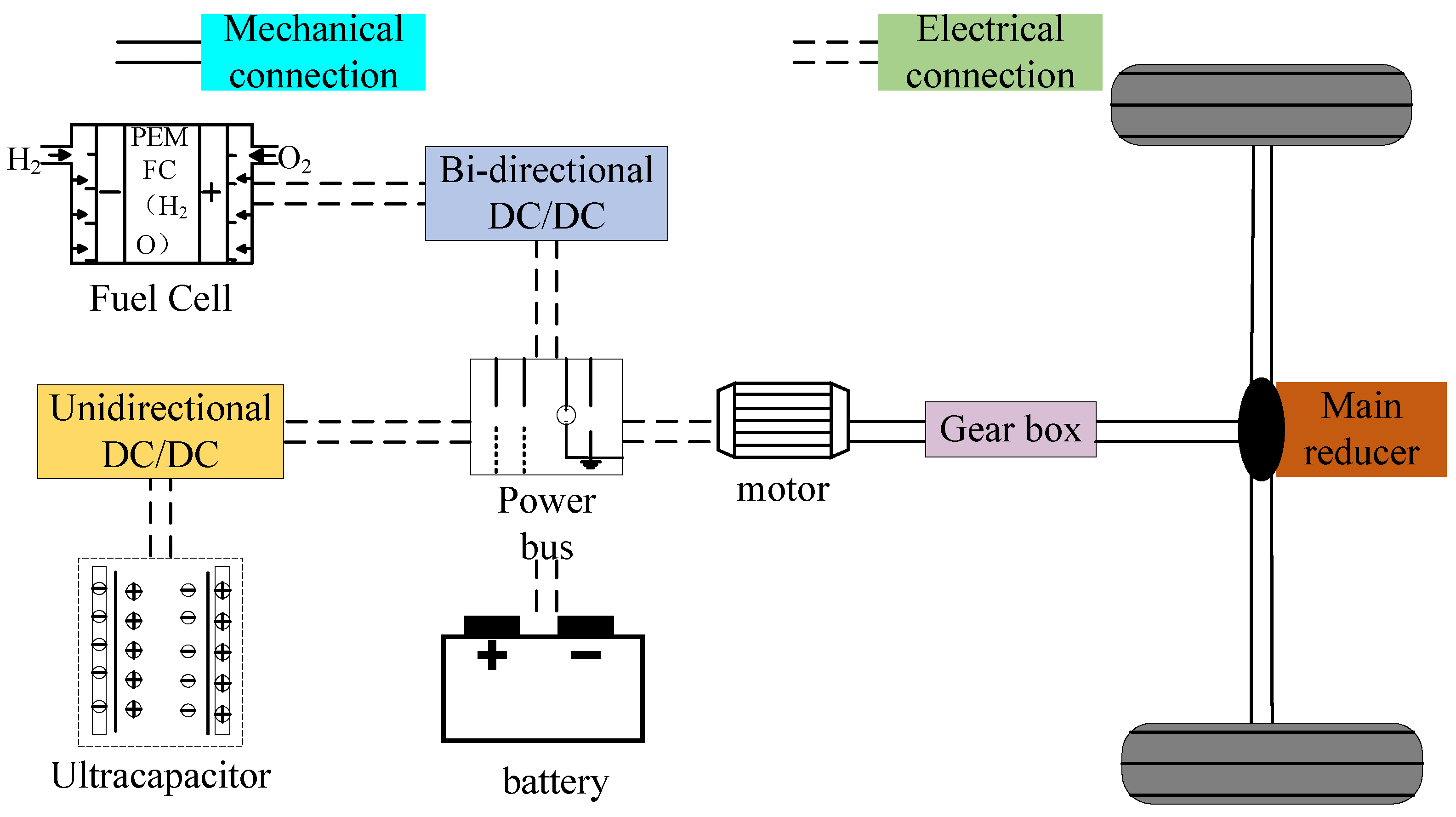
2.1. Vehicle Power System Structure

The power system structure of the fuel cell vehicle is illustrated in Figure 1. The fuel cell is utilized as the primary energy source to produce most of the demanded power, while the battery and ultracapacitor are used as auxiliary energy sources to provide the remaining power and recover braking energy. The battery is directly connected to the power bus, which means that the voltage of the power bus is determined by the rated voltage of the battery. A unidirectional DC/DC converter is applied to connect the fuel cell to the power bus to increase the voltage of the fuel cell. The ultracapacitor can recover braking energy, which is why a bidirectional DC/DC converter is provided to connect the ultracapacitor to the power bus. The power bus is connected to an AC/DC converter to provide alternating current power to the permanent magnet synchronous motor.

2.2. Dynamic Model and Parameters of Locomotive

The locomotive is subjected to several major forces during operation: the main traction force, the rolling resistance of the wheels, air resistance during running, climbing resistance and accelerating resistance [23]. The vehicle dynamics model is defined in Equation (1).
F = F w + F r + F i + F a F w = 0.5 ρ C A v 2 F r = m g C r cos θ F i = m g sin θ F a = G d a
where F, F w , F r , F i and F a are denoted as the main traction force, the air resistance during operation, the rolling resistance of the wheels, the climbing resistance and the acceleration resistance, respectively; ρ , v, θ and a are denoted as the air density, the actual speed of the vehicle, the slope of the road surface and the acceleration speed, respectively; C, A, C r and G d are regarded as the air resistance coefficient, the windward area of the vehicle, the rolling friction coefficient between the vehicle and the road surface and the inertial mass, respectively. The vehicle parameter information is listed in Table 1.
The required power to operate the vehicle can be calculated by Equations (2) and (3), which depict the relationship between the vehicle demand power and the power output of the three energy sources: the fuel cell, battery and ultracapacitor.
P m = F · v η m o t o r
P m = P f c · η u + P B + P u c · η b i
where η m o t o r , η u and η b i are denoted as the motor efficiency, the efficiency of the unidirectional DC/DC converter and the efficiency of the bidirectional DC/DC converter, respectively, and P f c , P B and P u c represent the output power of the fuel cell, battery and ultracapacitor, respectively.

2.3. Fuel Cell Model

The fuel cell in this paper is a proton exchange membrane hydrogen-oxygen fuel cell, which works by converting the chemical energy contained within hydrogen and oxygen into electrical energy through a redox reaction, and the fuel cell system is modeled by an empirical equation [25]. The relationship between fuel cell output power and hydrogen consumption is described in Equation (4).
m ˙ f c = 1 E H 2 , l o w P f c η f c P f c d t
where P f c is the fuel cell power; E H 2 , l o w is expressed as the low calorific value of hydrogen, equal to 120 kJ/kg; η f c P f c is defined as the efficiency when the fuel cell power is P f c ; m ˙ f c represents the hydrogen consumption.
The total power output of the fuel cell during operation is P H 2 . Since the auxiliary equipment carried by the fuel cell needs its power supply, the efficiency expression of the fuel cell system can be expressed by Equation (5).
η f c P f c = P f c P H 2
The fuel cell model FC_ANL50HZ is adopted in Advisor, and the relationship between its output power and efficiency is plotted in Figure 2. The graph demonstrates that when the fuel cell output power is very low or very high, its efficiency is in the low region. In order to improve the energy utilization of the whole vehicle and make the fuel cell work in the high-efficiency range, this paper controls the output of the fuel cell in [10 kW, 36 kW].

2.4. Battery Model

The battery is applied as an auxiliary energy source to reduce the burden of the fuel cell. In addition, the battery can also recover the braking energy of the vehicle. Considering that the battery energy comes from the fuel cell system and the characteristics of the battery charging and discharging, S O C B needs to be kept in a safe range, and S O C B is maintained at [0.4, 0.8].
In this paper, the Rint simplified model is chosen to build the equivalent model of the battery in ADVISOR. The voltage, current and S O C B under this model are calculated as Equation (6).
U b = U o c i R b U o c = N b f 2 ( S O C B ) i = U o c U o c 2 4 R b P b 2 R b
where U o c , R b and U b are expressed as the open-loop voltage of the battery, the internal resistance of the battery and the terminal voltage of the battery, respectively; i is the internal current of the battery; and f 2 ( S O C B ) is defined as the table lookup function regarding the internal SOC.
S O C B can be obtained by integrating the battery current and dividing it by the battery capacity, which is calculated by Equation (7).
S O C ( t + 1 ) = S O C ( t ) i Q d t

2.5. Ultracapacitor Model

The ultracapacitor has the characteristic of high power density, which can absorb and release very high power in a short period of time [26]. So, it can provide the high frequency part of the demanded power, which is helpful to extend the lifespan of the ultracapacitor and battery. Moreover, the ultracapacitor can also recover braking energy and improve the overall energy utilization. The model of the ultracapacitor is built by the RC model, whose current, voltage and S O C UC versus power can be expressed by Equation (8).
i c = U o u c U o u c 2 4 R u c P u c 2 R u c U o u c ( n + 1 ) = U o u c ( n ) i × d t C S O C U C = U o u c 2 U o u c _ max 2
where U o u c , R u c , P u c and C are denoted as the operating voltage of the ultracapacitor, the internal resistance of the ultracapacitor, the output power of the ultracapacitor and the equivalent capacitance of the ultracapacitor, respectively; i c is expressed as the current of the ultracapacitor; U o u c _ max 2 is defined as the average value of the maximum voltage of the ultracapacitor.

3. Design of Energy Management Strategy

The control strategy designed in this paper is divided into an upper-layer EMS and a lower-layer EMS. According to the vehicle operation status and the efficiency relationship of the fuel cell, the fuzzy controller is adopted in the upper EMS to distribute the motor required power between the FCS and the ESS. Based on the charging and discharging characteristics of the battery as well as the features of high power density of the ultracapacitor, an adaptive low-pass filter is utilized in the lower EMS to distribute the ESS demand power between the battery and the ultracapacitor. The structure diagram of the control strategy is displayed in Figure 3.

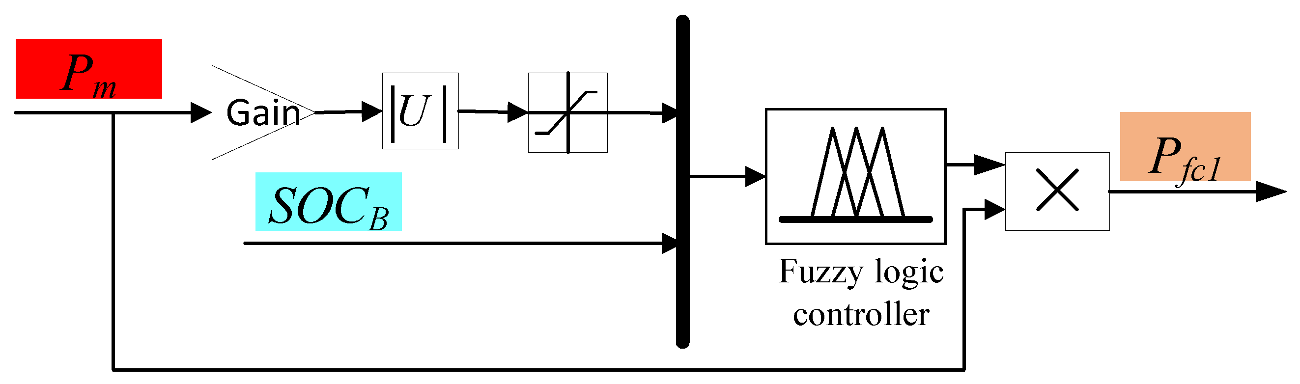
3.1. Upper-Layer Energy Management Strategy

The upper-layer EMS is labeled in the specified part of Figure 3, which consists of three main components: the fuzzy control module, status regulation module and switch control module. The purpose of the fuzzy control module is to obtain the proportional coefficient f from the motor demand power and S O C B . The fuel cell output power can be derived by multiplying the proportional coefficient with the motor power. The function of the status regulation module is to determine whether the vehicle is in the high or low energy consumption state by the average of the motor demand power per minute, and then make a revision of the fuel cell output power. In addition, this module will also revise the fuel cell output power by S O C B , so as to ensure that S O C B is always kept in the set range. The following section will introduce these two parts.
(1)
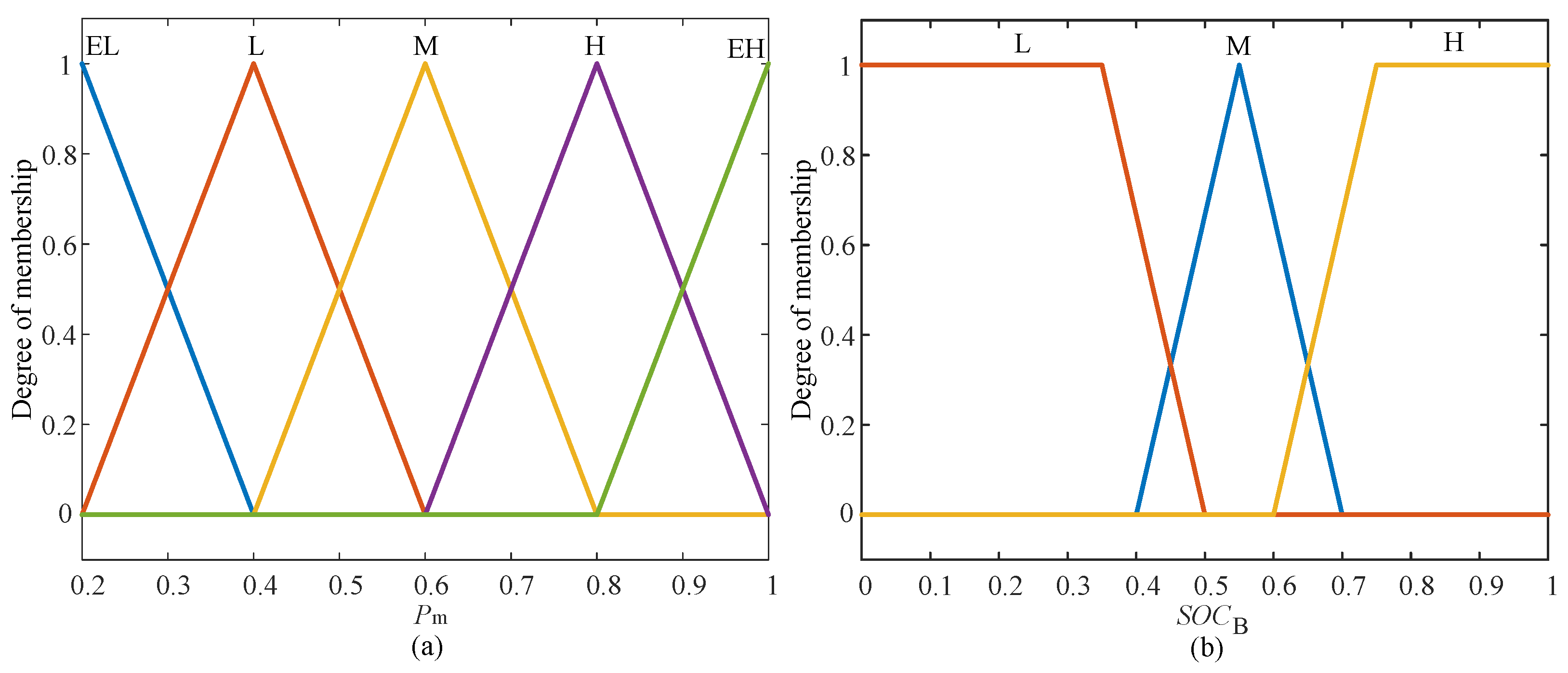
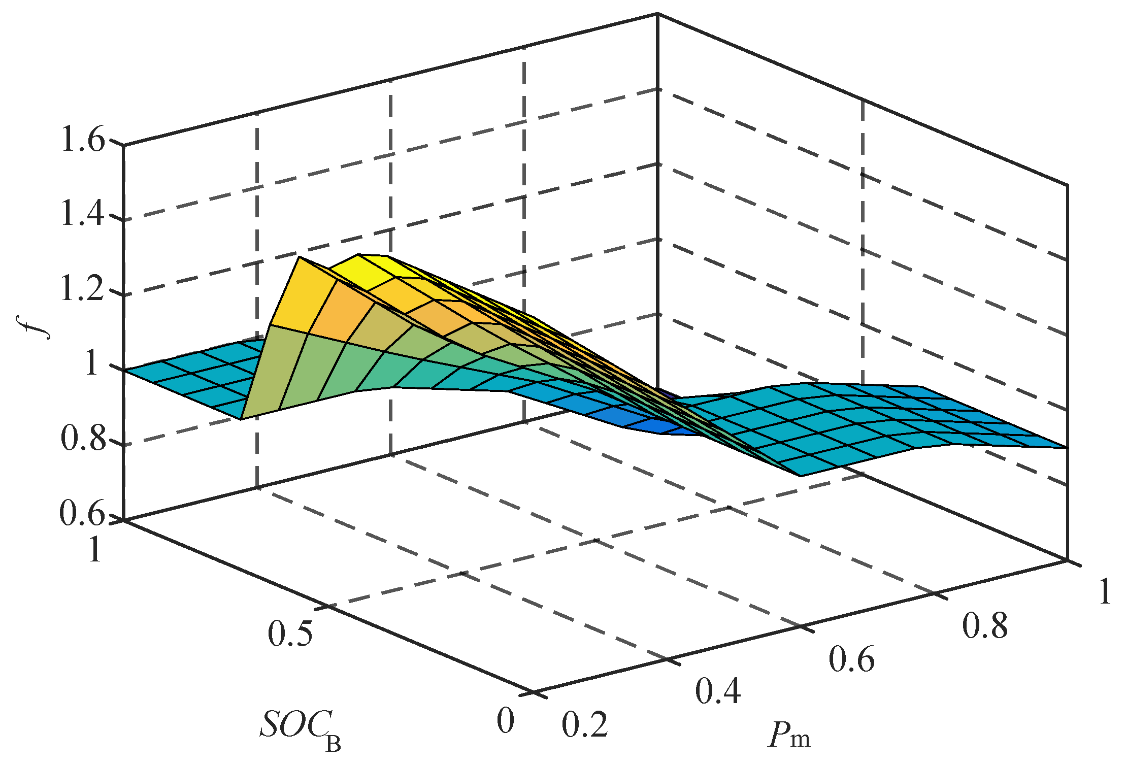
Design of fuzzy controller
Since the lower-layer EMS allocates the demand power of the ESS to the battery and the ultracapacitor with the judgment condition S O C UC , the ultracapacitor and the fuel cell can be influenced by S O C B in the energy allocation process. Hence, the input of the fuzzy controller is P m and S O C B , and the output is the proportional coefficient f. The physical domain of P m is [10 kW, 40 kW] and the fuzzy theoretical domain is [0.25, 1]. The physical domain of S O C B is [0, 1] and the fuzzy domain is [0, 1]. The values of constant function f are {0.6, 0.7, 0.8, 0.9, 1.0, 1.2, 1.3, 1.5, 1.6}. The fuzzy subsets of P m are EL , L , M , H , EH , representing extremely low , low , medium , high , extremely high , and the fuzzy subsets of S O C B are L , M , H , representing low , medium , high . Their affiliation functions are illustrated in Figure 4. The affiliation function of triangles is chosen for its large sharpness and more accurate blurring effect. And its design mainly considers the efficient operation of the fuel cell and the range of S O C B .
According to the power–efficiency relationship of the fuel cell, the charging and discharging characteristics of the battery are considered. The fuzzy rules are listed in Table 2, whose design should respect the following constraints.
(1)
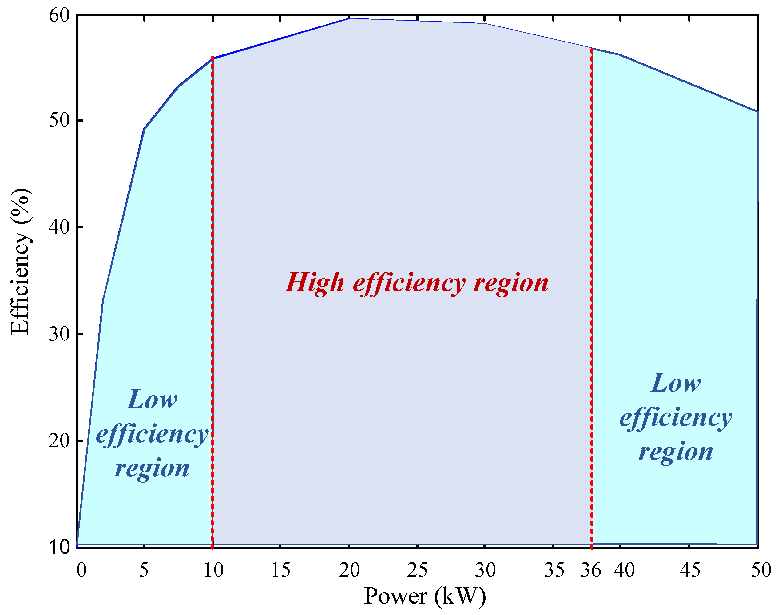
In order to increase overall vehicle efficiency, the fuel cell needs to work in the high-efficiency region, and according to Figure 2, the power range of the fuel cell is [10 kW, 36 kW].
(2)
The energy of the battery is supplied by a fuel cell, which means that it is necessary to ensure that the S O C B operates in the range [0.4, 0.8].
(3)
The fuel cell does not operate when the vehicle is in a low-energy state, which reduces hydrogen consumption and extends the lifespan of the fuel cell by reducing the switching frequency.
The surface diagram of the output characteristics of the fuzzy controller is displayed in Figure 5. The phenomenon can be observed that the larger the P m , the smaller the proportional coefficient f with a certain S O C B , which indicates that the output of the fuel cell is controlled within the high-efficiency range. When P m is constant, the proportional coefficient f decreases with the increase in S O C B , which is helpful to maintain S O C B . The model diagram of the fuzzy control section is shown in Figure 6. The conversion relationship between the required power and the output power of the fuzzy controller can be clearly seen in this diagram.
(2)
Design of the status regulator
The purpose of this module is to ensure that the fuel cell output power range is in the high-efficiency zone and to determine the energy consumption state of the vehicle by the average power per minute of the vehicle P m a v e to allocate power. The state differentiation and energy distribution are as follows.
(1)
When P m a v e P f c m i n , the vehicle is in a high energy consumption state. The energy distribution in this state is described in Equation (9).
P f c = P f c 1 P e s s = P m P f c
(2)
When P m a v e > P f c m i n , the vehicle is in a low energy consumption state. The energy distribution in this state is indicated in Equation (10).
P f c = 0 P e s s = P m S O C B > S O C B g o a l P f c = P f c m i n P e s s = P m P f c S O C B S O C B g o a l
S O C B g o a l can be calculated by Equation (11)
S O C B g o a l = S O C B U S O C B L 2
The purpose of the switch control module is to ensure that the S O C B is within the safe range and to control the switching of the fuel cell.

3.2. Lower-Layer Energy Management Strategy

This portion allocates power to the battery and ultracapacitor by the P e s s and S O C uc . With high power density and low energy density, the ultracapacitor is well suited to take up the high-frequency parts of the P m . Therefore, an adaptive low-pass filter is designed to distribute the higher-frequency portion of the demanded power to the ultracapacitor with the following mathematical equation.
y n = k x ( n ) + ( 1 + k ) y ( n 1 ) = y ( n 1 ) + k [ u ( t ) y ( t 1 ) ] k = d T T
where y ( n ) denotes the current output, x ( n ) represents the present input, y ( n 1 ) means the output at the upper moment and k is a time constant; the actual value depends on the filtering time constant (T) and the sampling period ( d T ).
The sampling time d T is a constant value, and the larger the time constant T, the narrower the passband of the filter. Both the ultracapacitor and battery can only be charged by fuel cells, so it is necessary to maintain their SOC near the desired value. Therefore, it is required to set the expected value for the S O C UC . When the vehicle is in drive, the ultracapacitor is supposed to have enough capacity to take the high-frequency part of the required power; the expected value of its charge state ( S O C U C g o a l ) is set to 0.3 at this time. When the vehicle is in the energy recovery state, the supercapacitor is required to have enough space to recover the braking energy. At this time, S O C U C g o a l = 0.9. In addition, the capacity of the filter is weakened as the SOC of the ultracapacitor gets closer to the desired value, allowing the battery to take on more power of the ESS. The passband frequency of the filter is determined by the relationship between S O C UC and T in Equation (13), where T f is the adjustment factor.
S O C U C = S O C U C S O C U C g o a l T = S O C U C T f ; S O C U C > T f T = d T ; S O C U C T f

4. Simulation Verification and Analysis

In order to verify the effectiveness of the designed EMS, a combined simulation model of Advisor and Matlab/Simulink is established. The control strategy model established in Matlab/Simulink is combined with the BD_FUELCELL model of Advisor, and the ultracapacitor model is added to obtain the simulation model of the whole vehicle.

4.1. Introduction to the Working Mode of the PFS

The conventional PFS is chosen to be analyzed in comparison with the proposed HEMS. There are four working modes of PFS, shown as below [27].
(1)
Startup mode.
The FCHEV is driven by the ESS at starting. After the fuel cell has completed warming up, the power is then distributed in real time according to the demand power and S O C B . The power distribution in this mode is given:
P f c = 0 P e s s = P m
(2)
Fuel cell working alone and charging mode to ESS.
At this moment, the SOC of the ESS is lower than the desired value, so the fuel cell not only provides the demand power but also charges the ESS to keep the SOC of the battery and ultracapacitor near the desired value. The power balance relationship of this pattern is illustrated as Equation (15).
P f c = P m + P e s s P e s s = α C S B _ c h a r g e _ p w r + β C S u c _ c h a r g e _ p w r α = S O C B S O C B g o a l S O C B U S O C B L / 2 β = S O C U C S O C U C g o a l S O C U C U S O C U C L / 2
where α and β are the power compensation coefficients of the battery and the ultracapacitor, respectively, and C S B _ c h a r g e _ p w r and C S u c _ c h a r g e _ p w r are the adjustment power of the battery and the ultracapacitor, respectively.
(3)
Fuel cell and the ESS common drive mode.
When the SOC of the ESS is higher than the desired value, or the fuel cell alone cannot meet the excessive motor demand power, the fuel cell and the ESS are jointly required to provide power to meet the working condition requirements. The power distribution is as the above Equation (15).
(4)
Deceleration or regenerative braking mode.
In this mode, the fuel cell is turned off and the motor turns into power generation state to charge the ESS, which increases the energy utilization of the whole vehicle.

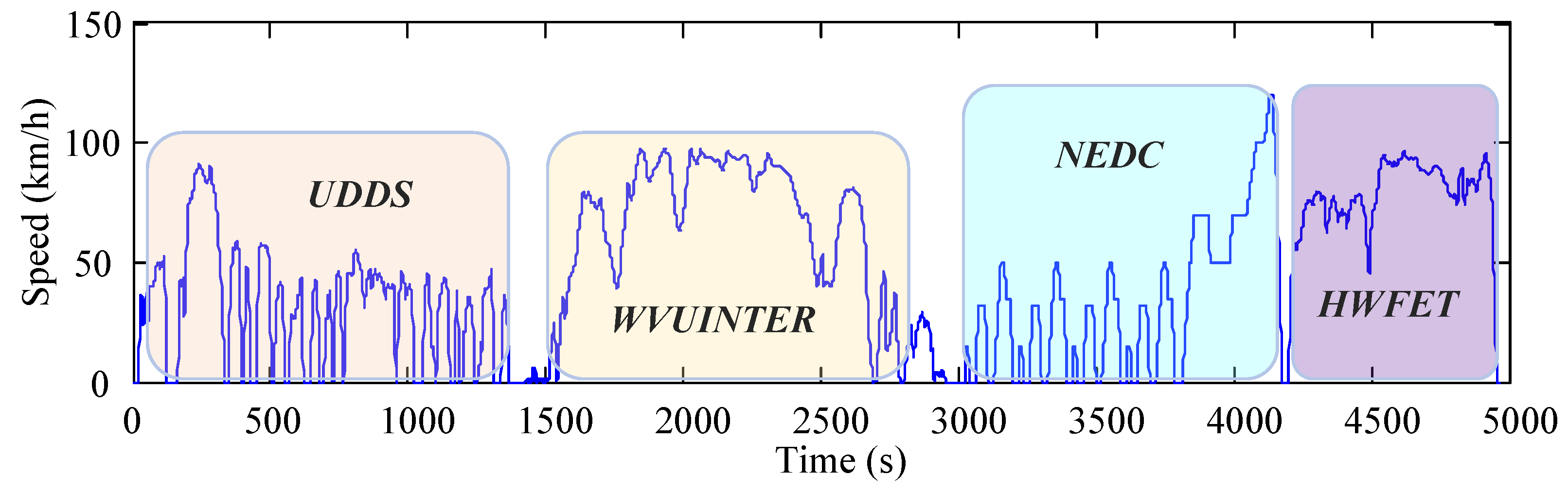
4.2. Simulation Conditions and Model Parameters

The selection of cyclic conditions is crucial for EMS testing. In order to validate the optimal mobility of the vehicle by HEMS, four different categories of cyclic conditions, UDDS, WVUINTER, NEDC and HWFET, are selected as the test conditions. The comprehensive performance of HEMS cannot be verified in a single condition; thus, the COMBINE, which is combined by four cycle conditions, is also implemented. The parameters of these cyclic conditions are listed in Table 3. The speed line plots for the COMBINE operating condition are illustrated in Figure 7, which has velocity characteristics of all other cyclic conditions. Only one cycle is executed, during the testing of EMS performance. This paper calculates the main parameters of the vehicle, and the results are shown in Table 4. The initial SOCs of the battery and ultracapacitor are 0.7, respectively.

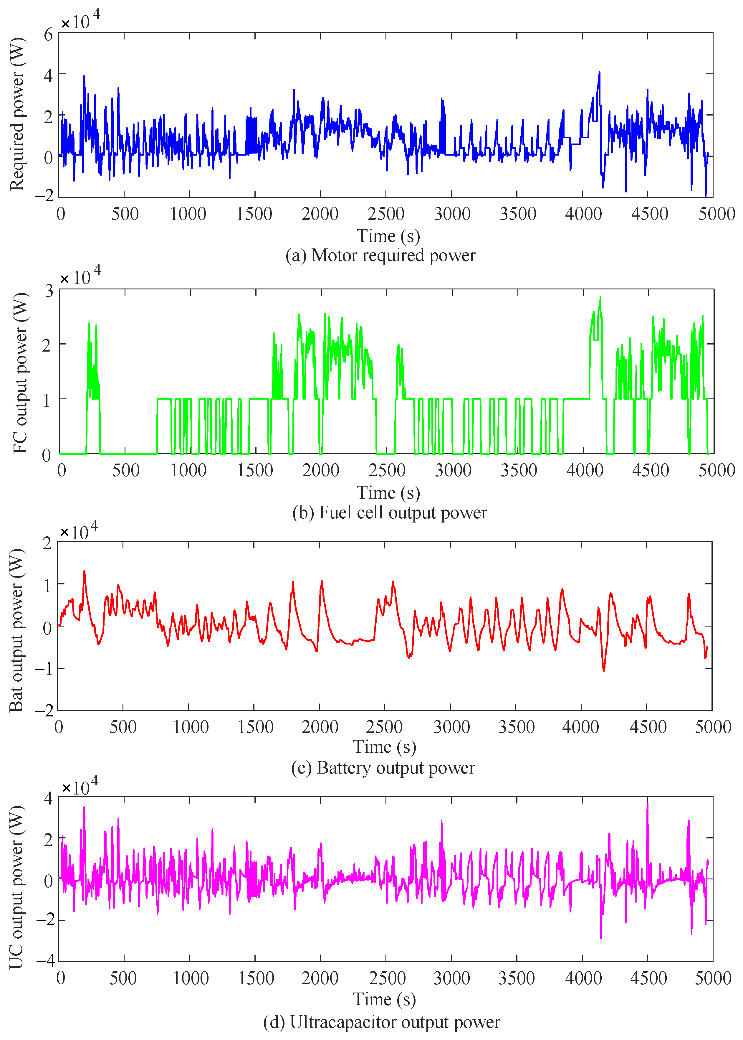
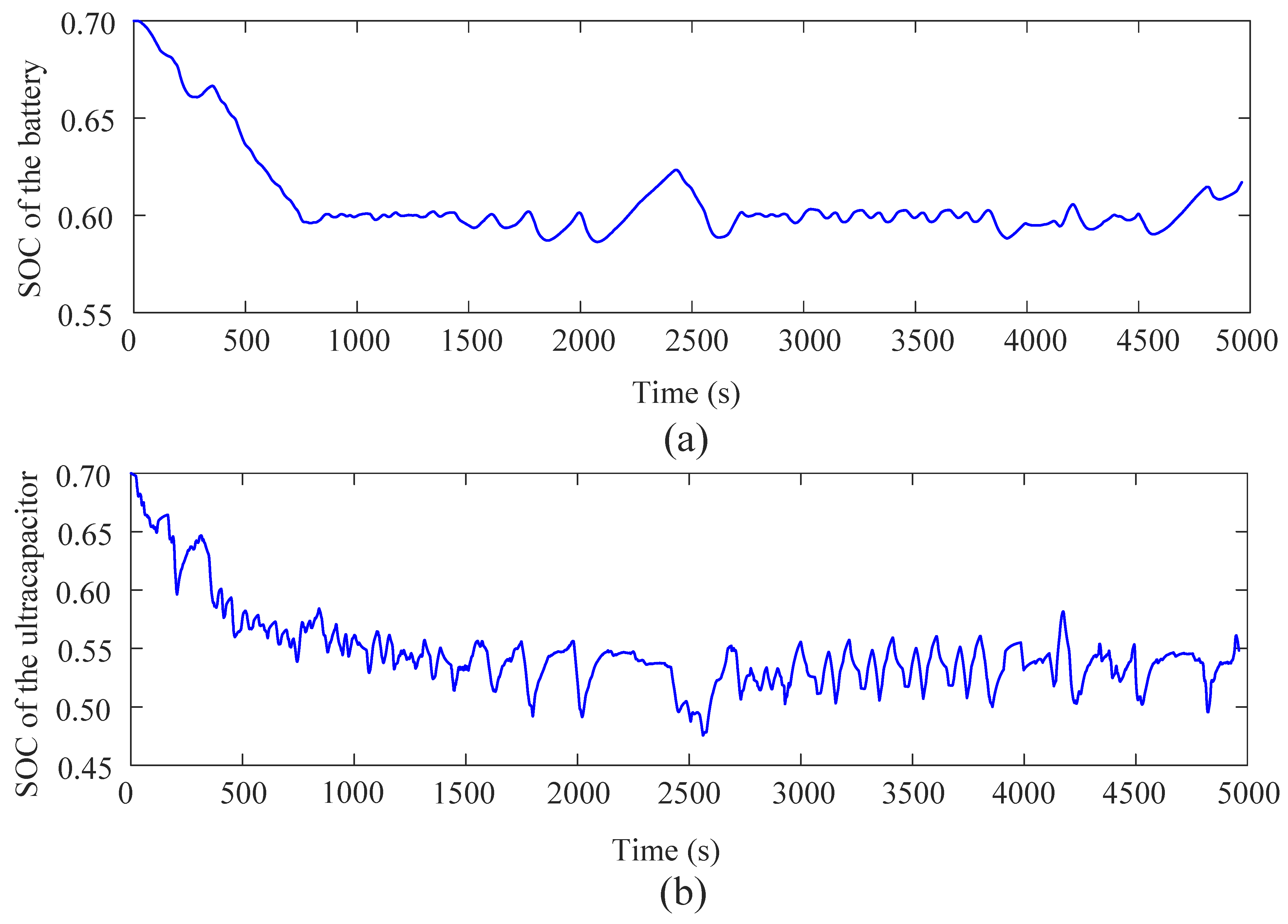
4.3. Results and Performance Analysis

In order to verify whether this proposed HEMS is economical and satisfies better dynamics, the economy is reflected in the energy utilization of the whole vehicle, the fuel cell hydrogen consumption and the equivalent hydrogen consumption of the ESS. Table 5 compares the economic performance of this two control strategies. It can be seen that the HEMS reduces fuel consumption by 50.7%, 23.0%, 54.5%, 7.6% and 9.4% compared with PFS under these four cycle conditions and the COMBINE cycle condition, respectively. The overall vehicle energy efficiency increased by 54.4%, 18.3%, 61.3%, 6.6% and 4.3%, respectively. From these data, this HEMS reduces hydrogen consumption and increases the overall vehicle energy efficiency, which meets the design requirements and improves the vehicle economy.
In Figure 8, the power output of the three energy sources can be visualized under the COMBINE operating condition. The output power of the fuel cell is in the high-efficiency region, and provides charging for the EMS. The battery relieves the burden of the fuel cell and maintains a stable operational status. The ultracapacitor provides peak power and high-frequency power, which plays the role of “peak-shaving”. Figure 9 shows that the SOC of the battery and ultracapacitor are maintained at their expected values with an error of less than ±0.5, respectively, when the operating time is 800 s. The design requirements of the EMS are met.
It has been experimentally proven that the dynamic performance of the vehicle is the same under different test conditions of the same EMS, which means the dynamic performance is only influenced by the EMS, independent of the choice of cycling conditions. In this paper, the acceleration performance, driving distance within 5 s and hill climbing ability of the two strategies are compared under the UDDS cycle condition to verify whether the HEMS meets the dynamic performance requirements, and the comparison results are presented in Table 6.
As can be seen from Table 6, the HEMS is faster than the PFS in all tests in terms of acceleration performance. At 48.3 km/h, the HEMS has an 8.4% improvement in climbing rate. Overall, the HEMS proposed in this paper has better improvement in power performance. Under the action of these two EMSs, the capacity diagram of four cycle conditions is shown in Figure 10, which indicates that the HEMS has different degrees of the optimization effect in each cycle condition. The best effect on vehicle economy improvement is achieved in the NEDC cycle condition. Therefore, this strategy has better performance in terms of both economy and dynamics.

5. Conclusions

In order to reduce the fuel consumption and improve the overall vehicle energy efficiency of FCHEV, this paper proposes an HEMS, which is modeled in Matlab/Simulink and cosimulated with Advisor to verify the vehicle performance under it. The upper-layer energy management strategy uses the combination of fuzzy controller and status regulator to allocate the required power reasonably and extend the lifespan of fuel cell. The lower-layer EMS applies a adaptive low-pass filter to distribute the high-frequency portion of the required power to the ultracapacitor, which fully exploits the high-power-density characteristics of the ultracapacitor. Lastly, a comparison is made with the traditional PFS under four typical cyclic operating conditions. In addition, the acceleration and hill climbing performance is verified in order to avoid the decrease in the vehicle’s dynamic performance. The following conclusions are obtained through simulation verification and experimental analysis.
(1)
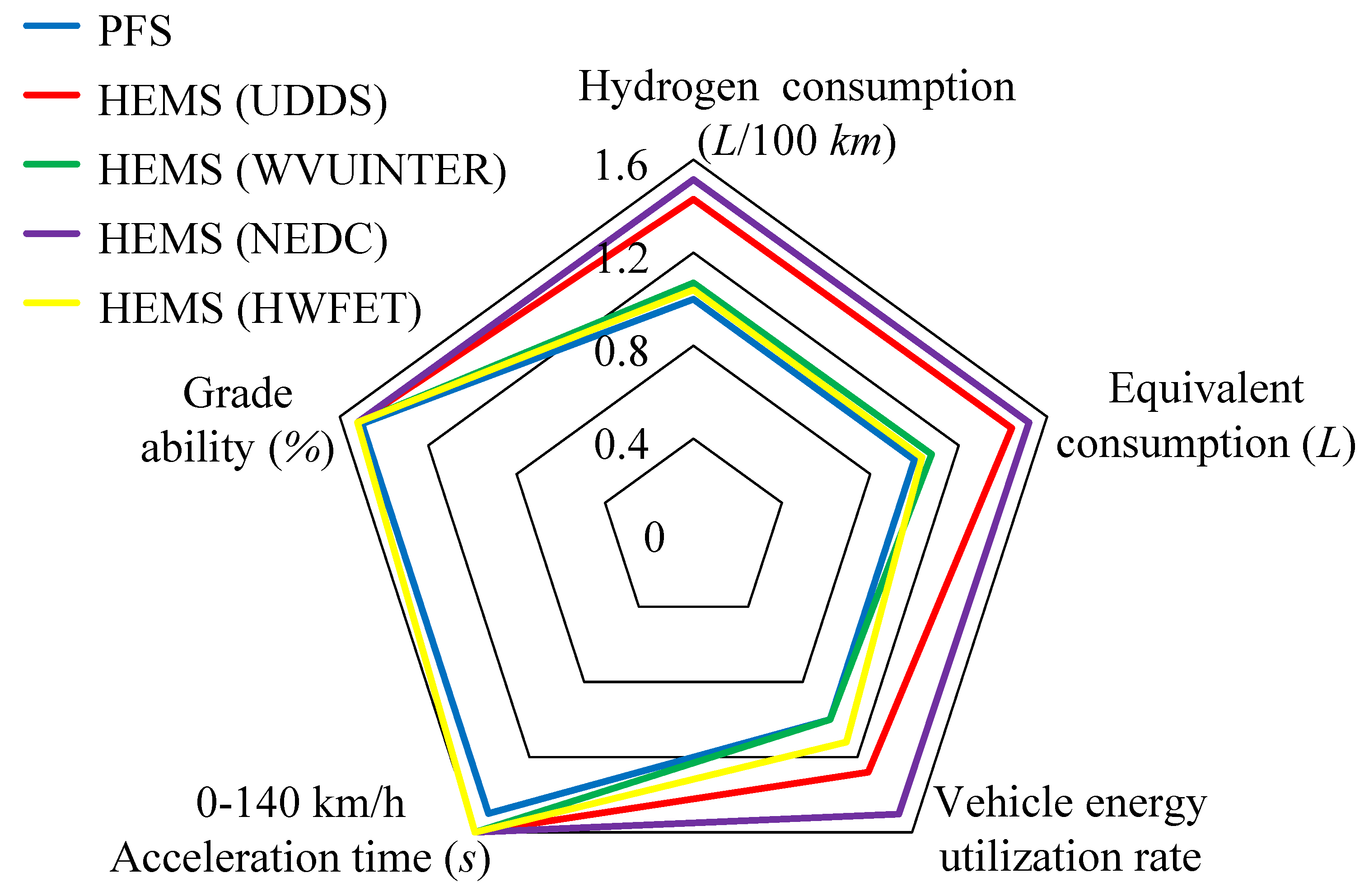
The proposed HEMS saves 9.4% of hydrogen and increases the energy utilization by 4.3% compared to the PFS under the COMBINE condition, which indicates better vehicle fuel economy of the HEMS.
(2)
This HEMS has shorter acceleration time and stronger climbing ability, which indicates that the vehicle dynamic performance is improved. Therefore, the EMS proposed will be a novelty approach to the EMS of hybrid vehicles.
Both this paper and the previous EMS based on fuzzy control improve the vehicle economy, but the simulation results show that curve fluctuation of the S O C B and S O C UC is lower, which is beneficial for prolonging their lifespan. In addition, although the introduction of the state regulator reduces the switching frequency of the fuel cell, its ability needs to be improved from the experimental results. And the optimization of the fuzzy controller and the damping factor of all energy sources require further consideration.

Author Contributions

Conceptualization: X.J. wrote this article, designed this energy control strategy, drew the figures and performed the simulation as well as the experiment. M.Z. supervised the study, coordinated the investigations and checked the manuscript’s logical structure. All authors have read and agreed to the published version of the manuscript.

Funding

This research was funded by the Natural Science Foundation of China under Grant No. 61563045. and in part by the International Cooperation Projects of Shihezi University under Grant GJHZ202003.

Institutional Review Board Statement

Not applicable.

Informed Consent Statement

Not applicable.

Data Availability Statement

Not applicable.

Conflicts of Interest

The authors declare no conflict of interest.

Abbreviations

The following abbreviations are used in this manuscript:
FCHEVFuel cell hybrid electric vehicles
EMSEnergy management strategy
ADVISORAdvanced Vehicle Simulator
UDDSUrban dynamometer driving schedule
WVUINTERWest Virginia Interstate Driving Schedule
NEDCNew european drive cycle
HWFETHighway fuel economy certification test
COMBINECombined cycle conditions for UDDS, WVUINTER, NEDC and HWFET
SOCState of charge
ESSEnergy storage system
FCSFuel cell system
PFSPower following management strategy
HEMSHierarchical energy management strategy
SOC B SOC of battery
SOC B g o a l Target SOC value for battery
SOC UC SOC of ultracapacitor
SOC UC g o a l Target SOC value for ultracapacitor
P e s s Required power for energy storage system
P m Motor demand power
P f c Fuel cell output power
P f c 1 The output power of the fuel cell after one correction
P f c 2 The output power of the fuel cell after two corrections
P f c m a x Upper limit of fuel cell power
P f c m i n Lower limit of fuel cell power
S O C B U Upper limit of battery SOC
S O C B L Lower limit of battery SOC
fFuzzy controller output scale coefficient
P f c r e q Fuel cell required power
P b r e q Battery required power
CSB_charge_pwrThe adjustment power of the battery
CSuc_charge_pwrThe adjustment power of the ultracapacitor
P u c r e q Supercapacitor required power
P f c a v a The power available from the fuel cell
P e s s a v a The power available from the energy storage system
S O C UC U Upper limit of ultracapacitor SOC
S O C UC L Lower limit of battery SOC
engine_onFuel cell switch
P m a v e Average power demand per minute

References

  1. Emadi, A.; Williamson, S. Fuel cell vehicles: Opportunities and challenges. In Proceedings of the IEEE Power Engineering Society General Meeting, Arlington, TX, USA, 9–12 September 2004; Volume 2, pp. 1640–1645. [Google Scholar] [CrossRef]
  2. Barbir, F.; Yazici, S. Status and development of PEM fuel cell technology. Int. J. Energy Res. 2008, 32, 369–378. [Google Scholar] [CrossRef]
  3. Fu, Z.; Li, Z.; Si, P.; Tao, F. A hierarchical energy management strategy for fuel cell/battery/supercapacitor hybrid electric vehicles. Int. J. Hydrogen Energy 2019, 44, 22146–22159. [Google Scholar] [CrossRef]
  4. Manoharan, Y.; Hosseini, S.E.; Butler, B.; Alzhahrani, H.; Krohn, J. Hydrogen Fuel Cell Vehicles; Current Status and Future Prospect. Appl. Sci. 2019, 9, 2296. [Google Scholar] [CrossRef] [Green Version]
  5. Ahmadi, S.; Bathaee, S.M.T.; Hosseinpour, A.H. Improving fuel economy and performance of a fuel-cell hybrid electric vehicle (fuel-cell, battery, and ultra-capacitor) using optimized energy management strategy. Energy Convers. Manag. 2018, 160, 74–84. [Google Scholar] [CrossRef]
  6. Anbarasu, A.; Dinh, T.Q.; Sengupta, S. Novel enhancement of energy management in fuel cell hybrid electric vehicle by an advanced dynamic model predictive control. Energy Convers. Manag. 2022, 267, 115883. [Google Scholar] [CrossRef]
  7. Li, X.; Wang, Y.; Yang, D.; Chen, Z. Adaptive Energy Management Strategy for Fuel Cell/Battery Hybrid Vehicles using Pontryagin’s Minimal Principle. J. Power Sources 2019, 440, 227105. [Google Scholar] [CrossRef]
  8. Desantes, J.; Novella, R.; Pla, B.; Lopez-Juarez, M. Effect of dynamic and operational restrictions in the energy management strategy on fuel cell range extender electric vehicle performance and durability in driving conditions. Energy Convers. Manag. 2022, 266, 115821. [Google Scholar] [CrossRef]
  9. Tao, F.; Zhu, L.; Ji, B.; Si, P.; Fu, Z. Energy Management Strategy Using Equivalent Consumption Minimization Strategy for Hybrid Electric Vehicles. Secur. Commun. Netw. 2020, 2020, 6642304. [Google Scholar] [CrossRef]
  10. Lu, H.; Tao, F.; Fu, Z.; Sun, H. Battery-degradation-involved energy management strategy based on deep reinforcement learning for fuel cell/battery/ultracapacitor hybrid electric vehicle. Electr. Power Syst. Res. 2023, 220, 109235. [Google Scholar] [CrossRef]
  11. Yang, H.-F.; Zhang, C.; Gong, X.; Hu, Y.-F.; Chen, H. Energy Management Strategy of Fuel Cell Hybrid Electric Vehicle Based on Dynamic Programming. In Proceedings of the 2020 Chinese Automation Congress (CAC), Shanghai, China, 6–8 November 2020. [Google Scholar]
  12. Kandidayeni, M.; Macias, A.; Boulon, L.; Kelouwani, S. Investigating the impact of ageing and thermal management of a fuel cell system on energy management strategies. Appl. Energy 2020, 274, 115293. [Google Scholar] [CrossRef]
  13. Pereira, D.F.; Lopes, F.d.C.; Watanabe, E.H. Nonlinear Model Predictive Control for the Energy Management of Fuel Cell Hybrid Electric Vehicles in Real Time. IEEE Trans. Ind. Electron. 2021, 68, 3213–3223. [Google Scholar] [CrossRef]
  14. Jia, C.; Qiao, W.; Cui, J.; Qu, L. Adaptive Model-Predictive-Control-Based Real-Time Energy Management of Fuel Cell Hybrid Electric Vehicles. IEEE Trans. Power Electron. 2023, 38, 2681–2694. [Google Scholar] [CrossRef]
  15. Liu, Y.; Zhu, L.; Tao, F.; Fu, Z. Energy Management Strategy of FCHEV Based on ECMS Method. In Proceedings of the 2019 8th International Conference on Networks, Communication and Computing, Luoyang, China, 13–15 December 2020; pp. 197–201. [Google Scholar] [CrossRef]
  16. Huangfu, Y.; Li, P.; Pang, S.; Tian, C.; Quan, S.; Zhang, Y.; Wei, J. An Improved Energy Management Strategy for Fuel Cell Hybrid Vehicles Based on Pontryagin’s Minimum Principle. IEEE Trans. Ind. Appl. 2022, 58, 4086–4097. [Google Scholar] [CrossRef]
  17. Luca, R.; Whiteley, M.; Neville, T.; Shearing, P.R.; Brett, D.J. Comparative study of energy management systems for a hybrid fuel cell electric vehicle—A novel mutative fuzzy logic controller to prolong fuel cell lifetime. Int. J. Hydrogen Energy 2022, 47, 24042–24058. [Google Scholar] [CrossRef]
  18. Yuan, H.B.; Zou, W.J.; Jung, S.; Kim, Y.B. A Real-Time Rule-Based Energy Management Strategy With Multi-Objective Optimization for a Fuel Cell Hybrid Electric Vehicle. IEEE Access 2022, 10, 102618–102628. [Google Scholar] [CrossRef]
  19. Zhai, D.; An, L.; Dong, J.; Zhang, Q. Switched Adaptive Fuzzy Tracking Control for a Class of Switched Nonlinear Systems Under Arbitrary Switching. IEEE Trans. Fuzzy Syst. 2018, 26, 585–597. [Google Scholar] [CrossRef]
  20. Li, Q.; Chen, W.; Li, Y.; Liu, S.; Huang, J. Energy management strategy for fuel cell/battery/ultracapacitor hybrid vehicle based on fuzzy logic. Int. J. Electr. Power Energy Syst. 2012, 43, 514–525. [Google Scholar] [CrossRef]
  21. Tao, F.; Zhu, L.; Fu, Z.; Si, P.; Sun, L. Frequency Decoupling-Based Energy Management Strategy for Fuel Cell/Battery/Ultracapacitor Hybrid Vehicle Using Fuzzy Control Method. IEEE Access 2020, 8, 166491–166502. [Google Scholar] [CrossRef]
  22. Farhadi Gharibeh, H.; Farrokhifar, M. Online Multi-Level Energy Management Strategy Based on Rule-Based and Optimization-Based Approaches for Fuel Cell Hybrid Electric Vehicles. Appl. Sci. 2021, 11, 3849. [Google Scholar] [CrossRef]
  23. Fu, Z.; Zhu, L.; Tao, F.; Si, P.; Sun, L. Optimization based energy management strategy for fuel cell/battery/ultracapacitor hybrid vehicle considering fuel economy and fuel cell lifespan. Int. J. Hydrogen Energy 2020, 45, 8875–8886. [Google Scholar] [CrossRef]
  24. Lü, X.; Wu, Y.; Lian, J.; Zhang, Y.; Chen, C.; Wang, P.; Meng, L. Energy management of hybrid electric vehicles: A review of energy optimization of fuel cell hybrid power system based on genetic algorithm. Energy Convers. Manag. 2020, 205, 112474. [Google Scholar] [CrossRef]
  25. Pielecha, I. Modeling of Fuel Cells Characteristics in Relation to Real Driving Conditions of FCHEV Vehicles. Energies 2022, 15, 6753. [Google Scholar] [CrossRef]
  26. Tao, F.; Gong, H.; Fu, Z.; Guo, Z.; Chen, Q.; Song, S. Terrain information-involved power allocation optimization for fuel cell/battery/ultracapacitor hybrid electric vehicles via an improved deep reinforcement learning. Eng. Appl. Artif. Intell. 2023, 125, 106685. [Google Scholar] [CrossRef]
  27. Tifour, B.; Moussa, B.; Ahmed, H.; Camel, T. Monitoring and control of energy management system for fuel cell hybrid in electrical vehicle using fuzzy approach. Diagnostyka 2020, 21, 15–29. [Google Scholar] [CrossRef]
Figure 1. The power system structure of the fuel cell vehicle.
Electronics 12 03428 g001
Figure 2. The relationship between the output power and efficiency of the fuel cell.
Electronics 12 03428 g002
Figure 3. The power flow diagram of the energy management strategy.
Electronics 12 03428 g003
Figure 4. The affiliation of P m and S O C B : (a) The affiliation of P m , (b) The affiliation of S O C B .
Electronics 12 03428 g004
Figure 5. The surface diagram of the output characteristics of the fuzzy controller.
Electronics 12 03428 g005
Figure 6. The model diagram of the fuzzy control module.
Electronics 12 03428 g006
Figure 7. The speed line plots for the COMBINE operating condition.
Electronics 12 03428 g007
Figure 8. The power output curve of each energy source under Combine cycle condition: (a) motor required power, (b) fuel cell output power, (c) battery output power, (d) ultracapacitor output power.
Electronics 12 03428 g008
Figure 9. The SOC variation curve under COMBINE cycle condition: (a) ultracapacitor SOC, (b) battery SOC.
Electronics 12 03428 g009
Figure 10. The capability comparison diagram of HEMS and PFS in various cycle conditions.
Electronics 12 03428 g010
Table 1. The vehicle parameter information.
Vehicle ParametersSymbolsValues
Air density (kg/m3) ρ 1.2
Coefficient of aerodynamic dragC0.335
Frontal area (m2)A2.0
Rolling resistance coefficient C r 0.6
Mass (kg)m1380
Wheelbase (m)r2.6
Table 2. The fuzzy rules.
f P m
ELLMHEH
SOC B L1.61.31.01.00.9
M1.51.21.00.80.7
H1.01.00.90.70.6
E: extremely, L: low, M: medium, H: high.
Table 3. The parameters of these four cycle conditions.
ParameterUDDSWVUINTERNEDCHWFETCOMBINE
Time (s)1369164011847654961
Distance (km)11.9924.9610.9316.5164.39
Average speed (km/h)31.5154.7533.2177.5846.71
Maximum speed (km/h)91.2597.7412096.4120
Average acceleration (m/s2)0.511.420.540.190.34
Average deceleration (m/s2)−0.58−1.86−0.79−0.22−0.39
Maximum acceleration (m/s)1.480.21.061.431.48
Maximum deceleration (m/s2)−1.48−0.21−1.39−1.48−1.86
Idle time (s)2591532986716
Number of stops17913140
Grade (%)00000
Table 4. The main parameters of the vehicle.
ComponentsTypeMain ParametersValues
MotorAC75Maximum power ( kW )75
Rated voltage ( V )320
Average efficiency (%)90
Fuel cell systemPEMFCMaximum net power ( kW )50
Average efficiency (%)56
BatteryPB25Capacity ( Ah )25
Rated voltage ( V )12
Number25
Maximum discharging5C
UltracapacitorMaxwellNumber150
Capacity ( Ah )2500
AC: alternating current; PEMFC: proton exchange membrane fuel cell; PB: plumbum.
Table 5. The economic performance of the two control strategies.
Driving ConditionsContrast ParametersPFSHEMSRates
UDDSFuel consumption (L/100 km)84.541.7 50.7 %
Equivalent consumption (L)5.72.8 50.9 %
Vehicle energy utilization rate0.1250.193 54.4 %
WVUINTERFuel consumption (L/100 km)5743.9 23.0 %
Equivalent consumption (L)3.93.0 23.0 %
Vehicle energy utilization rate0.2630.311 18.3 %
NEDCFuel consumption (L/100 km)82.637.6 54.5 %
Equivalent consumption (L)5.62.5 55.4 %
Vehicle energy utilization rate0.1630.263 61.3 %
HWFETFuel consumption (L/100 km)43.340.0 7.6 %
Equivalent consumption (L)2.92.7 6.9 %
Vehicle energy utilization rate0.3350.357 6.6 %
COMBINEFuel consumption (L/100 km)58.452.9 9.4 %
Equivalent consumption (L)43.6 10.0 %
Vehicle energy utilization rate0.2460.257 4.3 %
↓ This symbol represents a decrease in hydrogen consumption. ↑ This symbol is defined as an increase in the overall vehicle energy efficiency.
Table 6. The dynamics performance of the two control strategies under UDDS cycle condition.
Dynamic PropertiesPFSHEMS
0–100 km/h acceleration time (s)8.46.6
60–100 km/h acceleration time (s)53.2
0–140 km/h acceleration time (s)20.213.5
Maximum speed (km/h)157.1157.2
Maximum acceleration (m/s2)55
Distance in 5 s (m)60.161.9
400 m acceleration time (s)16.315.0
Grade ability (%)36.739.8
Disclaimer/Publisher’s Note: The statements, opinions and data contained in all publications are solely those of the individual author(s) and contributor(s) and not of MDPI and/or the editor(s). MDPI and/or the editor(s) disclaim responsibility for any injury to people or property resulting from any ideas, methods, instructions or products referred to in the content.

