Article

An Ultra-Wideband Integrated Filtering Antenna with Improved Band-Edge Selectivity Using Multimode Resonator

1
Key Laboratory of Functional Materials for Electronic Information (B), Huazhong University of Science and Technology, Wuhan 430074, China
2
Wenzhou Advanced Manufacturing Institute, Huazhong University of Science and Technology, Wenzhou 325035, China
3
Aerospace Nanhu Electronic Information Technology Co., Ltd., Wuhan 430074, China
*
Author to whom correspondence should be addressed.
Electronics 2023, 12(15), 3264; https://doi.org/10.3390/electronics12153264
Submission received: 3 July 2023 / Revised: 21 July 2023 / Accepted: 24 July 2023 / Published: 29 July 2023
(This article belongs to the Special Issue Broadband Antennas and Antenna Arrays)

Abstract

:
In this paper, a novel design of ultra-wideband (UWB) filtering antenna integrated with the multimode resonator (MMR) bandpass filter is proposed, aiming to enhance band-edge selectivity. At the beginning, a MMR bandpass filter is modified and studied. Based on the classic MMR filter, the proposed filter folds the microstrip transmission line to reduce its size while retaining the original filtering performance. Moreover, an open stub and short stub are added to the proposed filter to obtain a transmission of zero. Then, the folded filter with stubs and a UWB bow-tie antenna are integrated together to form a filtering antenna. The open stub and short stub in the MMR structure enhance the antenna’s upper and lower band-edge selectivity, respectively. Series of parameters are studied to analyze their influences on the frequency selection range and band-edge characteristics. Compared with the original UWB dipole antenna, such an integrated approach brings many benefits. Firstly, the UWB filter not only broadens the bandwidth of the device, but also improves band-edge selectivity, which can eliminate the unwanted passband near the operating frequencies. Secondly, the integrated system reduces the size and cost of the devices, which is very important in the miniaturization of wireless systems. In this research, the reflection coefficient ( S 11 ) of integrated filtering antenna is lower than −10 dB between 2.92 and 11.51 GHz, and it has a fractional bandwidth of 119%. The measured shape factor is 1.027 (very close to 1), which proves that this design has a better band-edge selectivity. Simultaneously, good radiation characteristics are also attained, with a maximum realized gain of 6 dBi. Theoretical simulation results are similar to the experimental results. The measurement results of the manufactured device effectively validate that its performances have reached the simulation design requirements.

1. Introduction

The ultra-wideband (UWB) system is a new technology of wireless communication, with the advantages of high confidentiality, high transmission rate, and low radiation, which is widely used in the field of wireless communication [1]. Since 2002, the US Federal Communications Commission (FCC) established ultra-wideband spectrum specifications, as experts and scholars conducted extensive research on ultra-wideband technology. It also has great application and research potential in the rapidly developing field of wireless communications today. The FCC classifies ultra-wideband systems into three categories: imaging systems [2], vehicular radar systems [3], and indoor ultra-wideband systems [4]. For different communication systems, the FCC has divided different frequency usage ranges. The antenna in this paper is applied in the third category of indoor ultra-wideband systems (5G, Wi-Fi, etc.) [1], which should meet the frequency requirement between 3.1 and 10.6 GHz. Although ultra-wideband (UWB) is widely used in wireless systems, it also faces many challenges, such as interference near frequency band, low positioning accuracy, the deterioration of the radiation characteristics, etc. [5].
To overcome these limitations, the major existing approach is to achieve both radiation and filtering by integrating filtering elements in the antenna design. In traditional device design, the filter and antenna are connected by a standard 50 ohms microstrip line, which may cause extra losses or unnecessary modes of operation. Due to bad matching, this will result in loss between the antenna and filter. Any power loss between the two devices will be directly translated into the noise figure. Thus, the integration of the filter and antenna can effectively reduce the loss [6]. Recently, many integrated filtering antennas with good radiation characteristics have been presented in [7,8]. However, they all have a narrow operating bandwidth, making them unable to meet the requirements for UWB applications. In order to remove the frequency constraint in operating, the method of using the multimode resonator (MMR) is reported in [9,10,11,12]. MMR was initially applied to the design of the broadband filter [13], which can generate multiple resonant modes and form an ultra-wide bandwidth by superimposing several modes. Nevertheless, MMR easily generates additional modes, so the band-edge selectivity of these antennas based on this structure is always poor. In practice, poor band-edge selectivity may lead to receiving other signals, seriously affecting the performance of the receiver.
To improve the band-edge selectivity, lots of research work has been carried out. Wu et al. proposed a printed unidirectional antenna, using parasitic loop and strips to improve the band-edge selectivity [14]. However, the shape factor (which can be denoted as the ratio of −3 dB bandwidth to −10 dB bandwidth) is high, up to 1.23. Moreover, the −10 dB bandwidth of this antenna is narrow (2.18–3.9 GHz), making it impossible to meet the UWB spectrum. In [15], by means of electromagnetic coupling, a circular radiating patch and UWB filter are formed to an integrated device. Due to the presence of the filter, it is possible to reduce the shape factor to 1.07. However, the size of this antenna is 53 mm × 42 mm, which is too large to be applied in the miniaturized RF front-end.
In addition, the type of radiation element needs to be concerned during the design of integrated filter antennas. The printed dipole antenna is applied for various wireless communication systems because of its flexible radiation characteristic, compact size, and easy integration. However, the printed dipole antenna has the disadvantage of a narrow bandwidth [16]. Many studies emphasized the design of the broadband dipole antenna [17,18,19] and how to extend the operating bandwidth [20,21,22]. According to [18,19], wideband printed bow-tie type antennas are developed, and their fractional bandwidths are 91% and 100%. Although their bandwidths are approximated by the UWB spectrum, the band-edge selectivity is poor. To extend the bandwidth of the dipole antenna, researchers have proposed various methods, such as transforming the shape of drivers [20], adding a parasitic patch [21], and using magnetic dipole antenna [22]. The increased bandwidth also introduces structural complexity, resulting in more difficult and costly processing.
In order to fulfill the characteristics of a wide operating bandwidth, good band-edge selectivity, high radiation characteristics, simple structure, and low cost, a new UWB antenna with an integrated filter is proposed in this paper. All of these were developed using Rogers Kappa-438 substrate ( ε r is 4.38, thickness is 1.0 mm, and tan δ is 0.005). Specifically, the proposed integrated filtering antenna mainly consists of a UWB bandpass filter and a bow-tie type dipole antenna. Using the proposed integration method, it can effectively eliminate the matching problem between the antenna and filter. The UWB bandpass filter based on the MMR consists of two symmetrical coupled microstrips and a low-impedance microstrip. In the middle of the low-impedance microstrip, there are an open stub and short stub, respectively. Due to these added stubs, a sharper skirt is realized at the band edge. Such a filter structure allows one to obtain a fractional passband of nearly 110%, which supports the ultra-wideband operation. In order to miniaturize the device, the filter is designed to be folded, which effectively reduces the length of the feedline. The Bow-tie type dipole antenna inherently has a large bandwidth. By connecting to a MMR filter, it achieves a good band-edge selectivity characteristic. Moreover, this filtering structure is based on microstrip and can be implemented on a single layer, realizing many advantages such as compactness and simple integration into other systems. Through manufacturing and actual testing, this approach allowed us to have a device with a maximum realized gain of 6 dBi and a fractional bandwidth up to 119%, which is centered at 7.2 GHz. The organization of this paper is as follows. Firstly, the proposed design of the UWB filter based on MMR is elaborated in Section 2. The design and simulated results of the bow-tie type antenna and its integrated UWB antenna are presented in Section 3. In Section 4, the proposed antenna are fabricated using a standard printed circuit board, and all the performances were experimentally verified in a wide frequency. Finally, the conclusion is presented in Section 5.

2. Proposed Folded UWB Filter

Before describing the design of the integrated filtering antenna, a folded UWB bandpass filter is first proposed. In order to minimize the dimension and improve the out-of-band rejection, we made a fold on the classical MMR structure and added some stubs. Figure 1 shows a comparison of three types of filter: the classical MMR [23], the folded MMR [24] and the proposed folded filter with stubs. The structure of the proposed filter with stubs is shown in Figure 1c. This method can reduce the length of the resonator to 30%. At the mean frequency of 6.85 GHz, the MMR contains two feedlines, two equally high impedance quarter-wavelength parallel coupled lines, one low-impedance transmission line, as well as open and short stubs paralleled in low impedance transmission lines. An aperture compensation technique is applied to the bottom end of the proposed filter, which can provide an effective enhancement of coupling strength in this structure [25].
The dimensions and their equivalent circuit are illustrated in Figure 2. Since the parallel coupled lines are capacitive, they can be directly converted into J-inverters. The value of the J-inverters are mainly related to L c , and s [6], which represents the J-inverter susceptance (J). θ 0 is the electrical length of the parallel coupled line, and its value is mainly controlled by L c . Between the symmetrical parallel coupled lines, there is a low-impedance microstrip, with an electrical length of θ 1 . At θ 1 / 2 , the open stub is connected to the short stub. In the MMR, the total electrical length is ϕ ( θ 0 + θ 0 + θ 1 ). Z 0 , Z a , and Z b represent the impedance parameters of the terminal, high impedance line, and low impedance line, respectively.
According to the above parameters, we analyze the design of the MMR based on the equivalent circuit. On the basis of the transmission line theory, the admittance parameter ( Y 0 ) at input port ( Z i n ) can be represented by J and ϕ . The reflection coefficient ( S 11 ) can be further expressed by the total electrical length ( ϕ ) and the normalized J ¯ ( J ¯ = J / Y 0 ) [25]:
S 11 = j 1 J ¯ 4 · tan ϕ 2 J ¯ 2 + j 1 + J ¯ 4 · tan ϕ
From Equation (1), each transmission pole is available ( S 11 = 0 ). When ϕ = 180 , 360 , or J ¯ = 1 , we can obtain the corresponding mode frequency. As shown in Figure 3, under different coupling distances ( s = 0.5 , 1 , 2 mm), the coupling intensity is variable. If the distance is far ( s = 2 mm), the MMR filter has three separate resonant frequencies ( f 1 , f 2 and f 3 ) within the target passband, which correspond to the three ϕ in Equation (1). The first three modes with f 1 , f 2 , and f 3 exit in the desired passband. With the enhancement of the coupling strength ( s = 0.5 mm), two extra poles are generated among the original poles, enabling the creation of a broader passband. When a tightly coupling degree ( s = 0.1 mm) can be achieved, the bandpass filter with MMR will be realized within an ultra-wideband frequency band. By further adjusting the gap and length of the coupling, it is possible to obtain a better S 21 and S 11 in the passband [26].
As depicted in Figure 2, we propose to load two identical high-impedance couple lines at the input/output ports. Each resonator in this model is central symmetrical, and the dimensions of the middle main resonator are L 2 and W 2 . In addition, the length of the stubs connected to the low-impedance line is L L 1 , L L 2 , and L L 3 , respectively. The short stub has a width of W l 2 and the open stub has a width of W l 1 . Two parallel coupled stubs on either side of the main resonator are denoted by length L c , and both stubs have the same length. All coupled lines have the same width of W c , and the gap between them is s. The dimensions of the feedline are L f in length and W f in width. On the bottom ground plane, the length of the aperture is L h and the width is W h . Detailed dimensions and structure information can be obtained from Figure 2.
The open and short stubs provide additional transmission poles within the passband. To further analyze the effects of various parameters on stubs, we mainly scanned the lengths L L 2 and L L 3 . From Figure 4a, it can be seen that the open stub creates resonance mainly near the upper passband. As the parameter of L L 2 decreases, this resonant mode gradually shifts to higher frequencies and eventually produces a transmission zero at the upper passband. Compared with the case without an open stub, a steeper transition band can be obtained, the size of the open stub has almost no effect at the lower passband. As illustrated in Figure 4b, the short stub affects the lower passband of the bandpass filter. With different lengths of the short stub, there are different band-edge selectivities around lower passband. When the short stub is not present, the bandwidth of the transition band is quite wide.
The simulated scattering parameter of the proposed filter (Figure 1c) and the classic one (Figure 1a) are plotted together in Figure 5. By comparing the simulation and measured results, it is evident that the low cut-off frequency of the UWB bandpass filter is 3.1 GHz and the high cut-off frequency is 10.6 GHz. In the operating band, the S 11 parameters are all less than −13 dB. This reveals that the proposed design has a fractional bandwidth of 110%, which is better than 42% and 108.10% in the references [27,28]. The simulated S 21 value at the center frequency (6.85 GHz) is −0.1 dB, with the minimum result of −0.5 dB in the whole UWB passband. Transmission zeros (TZs) exist at the upper and lower cutoff frequencies. By comparison with the classic one without stubs in Figure 5, it can be seen that after adding stubs in the folded filter, we obtain a sharper skirt and a better performance, which can be used as the feedline in the subsequent antenna design.

3. Integrated Filtering Antenna Design

In this work, the design of the UWB dipole antenna without filter is firstly carried out. Next, by connecting the folded filter with stubs proposed above, the overall design of the integrated filtering antenna is completed.

3.1. Single-UWB Antenna

As shown in Figure 6, the design begins with a classic printed bow-tie antenna, which can follow a rectangular microstrip antenna. We can derive the empirical formula on the basis of a rectangular patch [29]. The T M 10 mode is the dominant mode of the bow-tie antenna, and its resonant frequency can be obtained by following Equation [30]:
f r = c 4 ε e L ( 1.152 R t )
R t = L W a + 2 Δ l + W b + 2 Δ l W a + 2 Δ l 2 L 12 a + 2 Δ l
Δ l = h 0.412 ε e + 0.3 W i h + 0.262 ε e 0.258 W i h + 0.813
ε e = ε r + 1 2 + ε r 1 2 1 + 12 h W i 1 / 2
W i = W b + W a 2
where L 12 a is the length of the bow-tie antenna arm, and c is the velocity of light in free space. The thickness, relative and effective permittivity of the substrate are determined by h, ε r , and ε e . In addition, the other structural parameters are described in detail in Figure 6.
The influence of different variations in the bow-tie antenna is studied as follows. Figure 7a depicts the impact of W b on the bow-tie antenna. As W b keeps increasing, the passband gradually becomes narrower and the high cutoff frequency gradually becomes lower. Therefore, the variable W b mainly affects the impedance matching at high frequency. From Figure 7b, the length of the antenna arms L 12 a affects the resonant frequency. As the value of L 12 a increases, the upper passband gradually decreases. By altering the dimension of W b and L 12 a , and keeping W a constant, it is possible to change the working frequency. Since the edge impedance of the antenna is not 50 ohms, then the multi-stage matching network is necessary to the input port, but this method increases the length of the antenna. Through the above analysis, the bow-tie antenna is similar to a rectangular patch, yet it has a wider bandwidth [30].
After lots of parameter sweeping and optimization, the S 11 is shown in Figure 8 and detailed dimensions are shown in Figure 6. Over the frequency band ranging from 3.1 to 10.44 GHz, the simulated S 11 value is below −10 dB, but the out-of-band rejection of the classic bow-tie antenna is very poor. Below 20 GHz, there are multiple high modes at high frequencies and one unbalanced mode at low frequencies. Due to the microstrip antenna matching network being too long, it produces an unbalanced mode and a certain radiation. These unwanted passbands near the operating frequency will greatly affect the application. Also, the band-edge selectivity is poor. Subsequently, using the above filter in place of the feedline of the conventional bow-tie antenna, the S 11 value can be improved.

3.2. Proposed UWB Integrated Filtering Antenna

In order to improve the problem of poor out-of-band rejection and band-edge selectivity in classic bow-tie antenna, an integrated filtering antenna is designed. As depicted in Figure 9, the MMR can replace the multi-stage matching network, they can be directly connected without impedance transformation between the filter and antenna. So, the proposed folded filter with stubs is embedded in the feedline. By combining the UWB filter and antenna together, the matching performance has been optimized after tuning the parameter. In this design, a rectangular ground plane is placed on the bottom of the substrate and forms an integral part with the bottom dipole antenna. Due to the presence of the ground plane, the proposed folded filter with stubs is able to use the above band characteristics to adjust the antenna’s properties. The size of the stubs in the proposed antenna is very sensitive to parameter tuning, so a little parameter change may lead to a large change in the bandwidth and performance.
The band-edge selectivity can be evaluated by the shape factor K. In general, the shape factor is used to describe the transition band of the filter, which is described as the ratio of the stopband to passband. As it becomes closer to 1, the transition band becomes narrower. Since the integrated filtering antenna has the passband selection of the filter, the shape factor K can be used to describe its band-edge selectivity, which can be expressed by Equation (7) [31]:
K = B W 3 dB B W 10 dB
where B W 3 dB is the bandwidth of S 11 below −3 dB. B W 10 dB is the bandwidth of the S 11 below −10 dB. To obtain the improved band-edge selectivity, the influence of stubs lengths L L 2 and L L 3 are indicated in Figure 10. Figure 10a shows the effect of the open stub length L L 2 on the shape factor, which mainly affects the high frequencies. With the change in L L 2 , the frequency selection characteristics are changed significantly. Figure 10b shows how the length L L 3 affects the band-edge selectivity. In contrast to the open stub, the length L L 3 mainly affects the shape factor at low frequencies, and has no effect on the high frequencies. This corresponds to the analysis of the above filter. When L L 2 = 1.4 mm and L L 3 = 0.7 mm, an optimal value is achieved, which has the lowest shape factor K = 1.02 .
The S 11 of the integrated filtering antenna before and after integration with the UWB filter are compared in Figure 11. As illustrated in Figure 11, the integrated UWB filter can extend the bandwidth of bow-tie antenna. After integration, the proposed antenna could operate from 2.90 GHz to 11.60 GHz, with a fractional bandwidth of 120%. This design can eliminate the passband outside the target frequencies. Except for the target passband, no other modes exist below 20 GHz. The proposed antenna has strong interference rejection and band-edge selectivity. In contrast, the classic bow-tie antenna can easily introduce unwanted modes (unbalanced mode f m o d e 1 , high mode f m o d e 2 , f m o d e 3 , and f m o d e 4 ) and has poor band-edge selection characteristics. Poor characteristics may create risk in RF systems, which could potentially disturb wireless systems.
In summary, the key factor is the UWB MMR filter, which substitutes the matching network, broadens the fractional bandwidth of the narrowband antenna, and exhibits filtering characteristics. After lots of parameter sweeping and optimization in Ansoft HFSS 15.0, we obtained better results, such as those shown in Table 1.

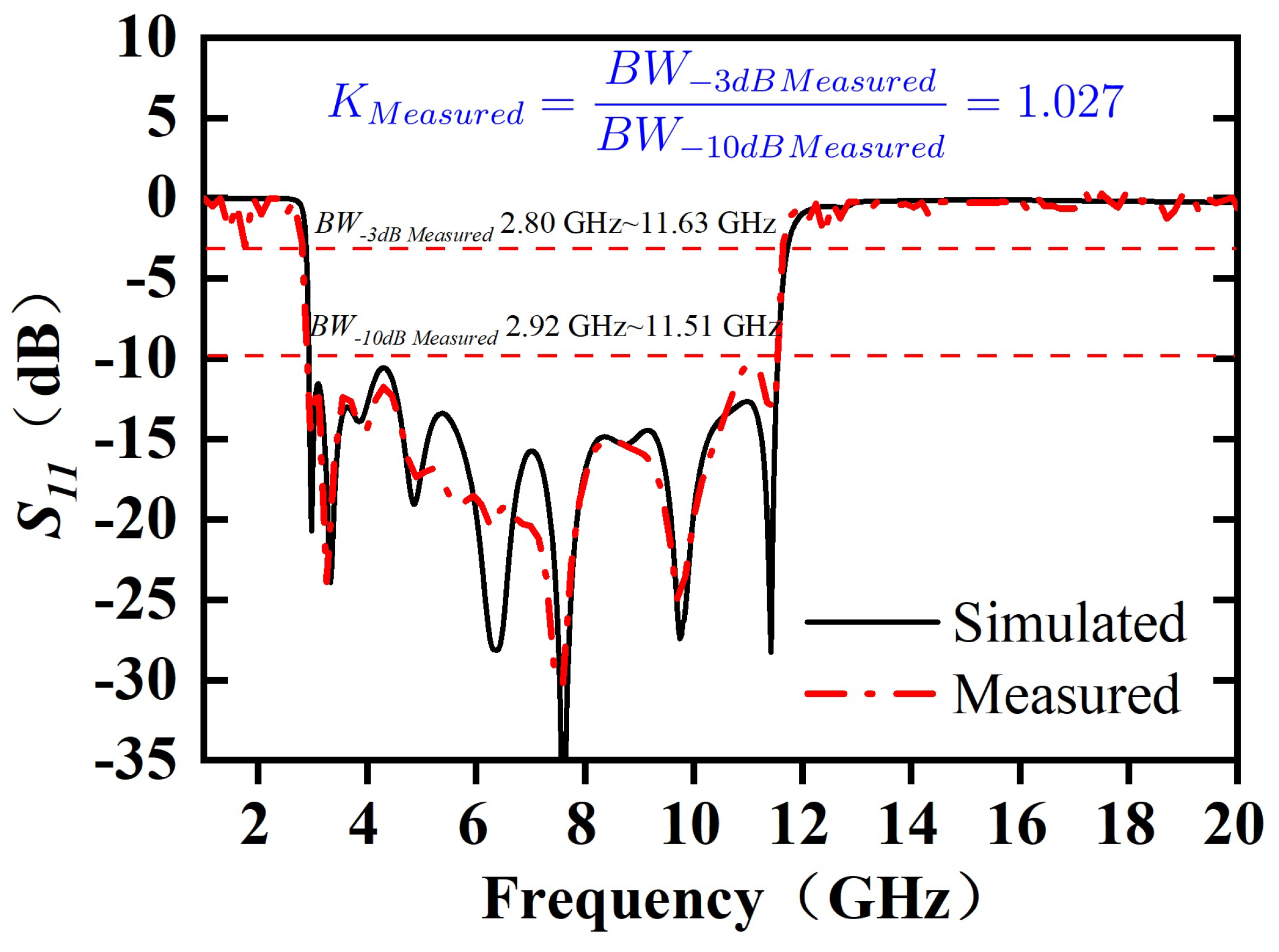
4. Simulated and Experimental Results

To prove the performance of the proposed ultra-wideband integrated filtering antenna, the prototype was fabricated and measured. As shown in Figure 12, the antenna prototype was based on the results of the above parametric study and manufactured using standard printed circuit board (PCB) technology. An SMA connector is soldered on the input port of the prototype. They all use CEYEAR network analyzer 3672D to measure S 11 and radiation characteristics.
The simulated and tested S 11 are presented together in Figure 13. From the figure, the tested and simulation results meet the requirements of the UWB spectrum. The measured −10 dB bandwidth is from 2.92 to 11.51 GHz, which has a fractional bandwidth of 119%. The tested results reveal that the target frequency and the design frequency is consistency. In addition, there is no other passband at low and high frequencies, which ensures that the antenna can resist noise in the operation. The measured shape factor is 1.027, which is almost equal to 1. A minor shape factor indicates that the proposed antenna has better band-edge selectivity.
To better demonstrate the band-edge selectivity of integrated filtering antenna, the simulated scattering parameters ( S 11 ), realized gain, and VSWR are shown in Figure 14. From Figure 14a, the value of VSWR not only meets the application of UWB, but also effectively suppresses undesired frequencies (unbalanced and high mode). Since there are two reflection zero point f T Z 1 and f T Z 2 at the high and low frequencies, the VSWR of proposed antenna increases rapidly out of passband, which are greater than 19 at 2.89 GHz and 11.85 GHz ( Γ > 0.9 ). As shown in Figure 14b, the peak simulated realized gain has little variation in the whole operating band, which is around 5–6 dBi (maximum realized gain is 6.8 dBi), and it declines rapidly beyond the cut-off frequencies. The radiation efficiency in the passband reaches 94.4%, and it drops to less than 10% in the out-of-band. Figure 15 presents a comparison of the measured and simulated radiation performance. Both the simulated and measured gain show a dramatic decrease when beyond the operating band. According to the measured results, the peak realized gain is 6 dBi. The measured antenna radiation efficiency is calculated using the measured gain and directivity [32], and a peak radiation efficiency of 83% is obtained.
Furthermore, the surface current distribution at different frequencies are illustrated in Figure 16. In the operating frequencies of the antenna (6.85 GHz), there is more surface current transfer to the radiation unit, and each resonator has a higher surface current. When the device is working outside the operating frequency (2.5 GHz and 12 GHz), the current transmitted to the antenna becomes lower and reflects back near the input port. This is mainly due to the impedance mismatch and a large reflection of the signal, which indicates that the device has the characteristics of a filter.
The radiation patterns for the H-plane ( y o z -plane) and E-plane ( x o y -plane) are shown in Figure 17, with frequencies of 3.5, 6.5, and 11 GHz, respectively. Due to the presence of reflective ground, the radiation patterns are similar to the directional antenna at lower frequencies. The magnetic fields indicate a main lobe at 0 degrees. In contrast, the radiation patterns begin to display distortion at high frequencies. When operating at higher frequencies, the distance between the antenna arm and the reflecting ground deviates from 1 / 4 λ , and there will be no isotropic reflection. Meanwhile, the current can be evenly distributed on the dipole antenna when the frequency is low. As the frequency increases to high frequency, the current distribution is not uniform. Therefore, the radiation performances at the high frequency band become different. The above analysis proves that a better radiation pattern can be obtained around center frequency, but the radiation pattern starts to deteriorate at high frequencies. According to the above comparisons, frequency deviations of approximately 3% for bandwidth between the simulated and tested results are noticed. This is mainly due to manufacturing errors, especially in the tolerance of via-hole and the deviation of the distance between the parallel coupled lines in MMR. Also, the difference between the simulated and measured efficiency is about 11%, and the peak realized gain drops by 0.8 dBi. These changes may be caused by the soldering loss. Although there are deviations between the simulated and the measured results, they are all within an acceptable range.
Finally, these are compared with related work, as shown in Table 2. It is evident that our design provides filtering characteristics, better out-of-band rejection and band-edge selectivity, a wider operating bandwidth, high radiation characteristics, etc. These attractive features effectively meet the requirements of UWB applications.

5. Conclusions

This paper introduces an integrated filtering antenna based on a microstrip UWB folded filter. The UWB folded filter is primarily designed through MMR, which has approximate quarter-wavelength parallel coupled lines at the feedline and a low impedance line between them. By adding open and short stubs in the low impedance line, it is possible to introduce transmission zeros at the low and high frequencies of the passband, respectively. Also, this structure can produce multiple transmission poles in the passband. Based on the integration approach, the folded filter with stubs and the UWB bow-tie antenna are integrated together to form a filtering antenna, which obtains a fractional bandwidth of more than 119%. Using this method, it can effectively eliminate the matching problem and another passband near the target operating frequencies. Furthermore, the open stub and short stub directly allow the antenna to obtain excellent band-edge selectivity at the high passband and low passband. By integrating the UWB filter and the dipole antenna, a wider working bandwidth is obtained, which is from 2.92 GHz to 11.51 GHz (meeting the UWB frequency spectrum). Simultaneously, good radiation characteristics are also attained. The measured results agree well with the simulation. According to the above results, it is possible to directly apply this antenna in the modern UWB systems. In the future, the substrates with a higher dielectric constant shall be used, which can minimize the thickness and size of the integrated filtering antenna.

Author Contributions

Conceptualization, M.Z. and W.L. (Wen Lei); methodology, X.W.; software, P.L.; validation, Z.Z., J.Y., and C.Y.; formal analysis, M.Z.; investigation, C.Z.; resources, W.L. (Wenzhong Lu); data curation, C.Z.; writing—original draft preparation, M.Z.; writing—review and editing, W.L. (Wen Lei); visualization, W.L. (Wenzhong Lu); supervision, P.L.; project administration, W.L. (Wen Lei); funding acquisition, W.L. (Wen Lei). All authors have read and agreed to the published version of the manuscript.

Funding

This work was supported by the Fundamental Research Funds for the Central Universities under Grant YCJJ202202008 and Joint Funds of the National Natural Science Foundation of China—Key Program (Grant No. U21B2068).

Institutional Review Board Statement

Not applicable.

Informed Consent Statement

Not applicable.

Data Availability Statement

Please contact Wen Lei at wenlei@mail.hust.edu.cn.

Conflicts of Interest

The authors declare no conflict of interest.

References

  1. Federal Communications Commission. Revision of Part 15 of the Commission’s Rules Regarding Ultra-Wideband Transmission Systems; Federal Communications Commission: Washington, DC, USA, 2002; pp. 98–153.
  2. Mahmud, M.Z.; Islam, M.T.; Misran, N.; Almutairi, A.F.; Cho, M. Ultra-Wideband (UWB) Antenna Sensor Based Microwave Breast Imaging: A Review. Sensors 2018, 18, 2951. [Google Scholar] [CrossRef] [Green Version]
  3. Balderas, L.I.; Reyna, A.; Panduro, M.A.; Del Rio, C.; Gutiérrez, A.R. Low-Profile Conformal UWB Antenna for UAV Applications. IEEE Access 2019, 7, 127486–127494. [Google Scholar] [CrossRef]
  4. Karoui, M.S.; Ghariani, N.; Lahiani, M.; Ghariani, H. A Compact UWB Elliptic Antenna for Indoor Localization System. IEICE Electron. Express 2019, 16, 20190425. [Google Scholar] [CrossRef]
  5. Ahmed, S.; Kim Geok, T.; Alias, M.Y.; Hossain, F.; Alsariera, H.; Abdaziz, A.; Soh, P.J. A UWB Antenna Array Integrated with Multimode Resonator Bandpass Filter. Electronics 2021, 10, 607. [Google Scholar] [CrossRef]
  6. Chuang, C.T.; Chung, S.J. Synthesis and Design of a New Printed Filtering Antenna. IEEE Trans. Antennas Propag. 2011, 59, 1036–1042. [Google Scholar] [CrossRef]
  7. Yang, S.J.; Cao, Y.F.; Pan, Y.M.; Wu, Y.; Hu, H.; Zhang, X.Y. Balun-Fed Dual-Polarized Broadband Filtering Antenna Without Extra Filtering Structure. IEEE Antennas Wirel. Propag. Lett. 2020, 19, 656–660. [Google Scholar] [CrossRef]
  8. Yang, W.; Chen, S.; Xue, Q.; Che, W.; Shen, G.; Feng, W. Novel Filtering Method Based on Metasurface Antenna and Its Application for Wideband High-Gain Filtering Antenna with Low Profile. IEEE Trans. Antennas Propag. 2018, 67, 1535–1544. [Google Scholar] [CrossRef]
  9. Panda, J.R.; Kakumanu, P.; Kshetrimayum, R.S. A Wide-Band Monopole Antenna in Combination With a UWB Microwave Band-Pass Filter for Application in UWB Communication System. In Proceedings of the 2010 Annual IEEE India Conference (INDICON), Kolkata, India, 17–19 December 2010; pp. 1–4. [Google Scholar]
  10. Huang, X.; Cheng, C.; Zhu, L. An Ultrawideband (UWB) Slotline Antenna Under Multiple-Mode Resonance. IEEE Trans. Antennas Propag. 2011, 60, 385–389. [Google Scholar] [CrossRef]
  11. Ranjan, P.; Raj, S.; Upadhyay, G.; Tripathi, S.; Tripathi, V.S. Circularly Slotted Flower Shaped UWB Filtering Antenna with High Peak Gain Performance. AEU Int. J. Electron. Commun. 2017, 81, 209–217. [Google Scholar] [CrossRef]
  12. Xu, F.; Chen, X.; Wang, X.A. UWB Antenna with Triple Notched Bands Based on Folded Multiple-Mode Resonators. IEICE Electron. Express 2012, 9, 965–970. [Google Scholar] [CrossRef] [Green Version]
  13. Lei, Z.; Sheng, S.; Menzel, W. Ultra-Wideband (UWB) Bandpass Filters Using Multiple-Mode Resonator. IEEE Microw. Wirel. Compon. Lett. 2005, 15, 796–798. [Google Scholar]
  14. Wu, J.; Zhao, Z.; Nie, Z.; Liu, Q.H. A Printed Unidirectional Antenna with Improved Upper Band-Edge Selectivity Using a Parasitic Loop. IEEE Trans. Antennas Propag. 2015, 63, 1832–1837. [Google Scholar] [CrossRef]
  15. Sahoo, A.K.; Gupta, R.D.; Parihar, M.S. Highly Selective Integrated Filter Antenna for UWB Application. Microw. Opt. Technol. Lett. 2017, 59, 1032–1037. [Google Scholar] [CrossRef]
  16. Choi, S.H.; Park, J.K.; Kim, S.K.; Park, J.Y. A New Ultra-Wideband Antenna for UWB Applications. Microw. Opt. Technol. Lett. 2004, 40, 399–401. [Google Scholar] [CrossRef]
  17. Wu, J.; Zhao, Z.; Nie, Z.; Liu, Q.H. A Broadband Unidirectional Antenna Based on Closely Spaced Loading Method. IEEE Trans. Antennas Propag. 2013, 61, 109–116. [Google Scholar] [CrossRef]
  18. Kiminami; Hirata; Shiozawa. Double-Sided Printed Bow-Tie Antenna for UWB Communications. IEEE Antennas Wirel. Propag. Lett. 2004, 3, 152–153. [Google Scholar] [CrossRef]
  19. Eldek, A.; Elsherbeni, A.; Smith, C. Wide-Band Modified Printed Bow-Tie Antenna with Single and Dual Polarization for C - and X-Band Applications. IEEE Trans. Antennas Propag. 2005, 53, 3067–3072. [Google Scholar] [CrossRef]
  20. Zhu, Y.; Chen, K.; Tang, S.Y.; Yu, C.; Hong, W. Ultra-Wideband Strip-Loaded Slotted Circular Patch Antenna Array for Millimeter-Wave Applications. IEEE Antennas Wirel. Propag. Lett. 2023, 1, 1–5. [Google Scholar] [CrossRef]
  21. Tran, H.H.; Park, I.; Nguyen, T.K. Circularly Polarized Bandwidth-Enhanced Crossed Dipole Antenna with a Simple Single Parasitic Element. IEEE Antennas Wirel. Propag. Lett. 2017, 16, 1776–1779. [Google Scholar] [CrossRef]
  22. Trinh-Van, S.; Van Trinh, T.; Yang, Y.; Lee, K.Y.; Hwang, K.C. Bandwidth-Enhanced Low-Profile Magneto-Electric Dipole Antenna with Shorting Parasitic Elements. IEEE Access 2021, 9, 64852–64859. [Google Scholar] [CrossRef]
  23. Menzel, W.; Zhu, L.; Wu, K.; Bogelsack, F. On the Design of Novel Compact Broad-Band Planar Filters. IEEE Trans. Microw. Theory Tech. 2003, 51, 364–370. [Google Scholar] [CrossRef]
  24. Wang, H.; Chu, Q.X.; Gong, J.Q. A Compact Wideband Microstrip Filter Using Folded Multiple-Mode Resonator. IEEE Microw. Wirel. Compon. Lett. 2009, 19, 287–289. [Google Scholar] [CrossRef]
  25. Zhu, L.; Bu, H.; Wu, K. Aperture Compensation Technique for Innovative Design of Ultra-Broadband Microstrip Bandpass Filter. IEEE MTT-S Int. Microw. Symp. Dig. 2000, 1, 315–318. [Google Scholar]
  26. Zhu, L.; Menzel, W.; Wu, K.; Boegelsack, F. Theoretical Characterization and Experimental Verification of a Novel Compact Broadband Microstrip Bandpass Filter. In Proceedings of the 2001 Asia-Pacific Microwave Conference, Taipei, Taiwan, 3–6 December 2001; pp. 625–628. [Google Scholar]
  27. Chen, R.S.; Wong, S.W.; Zhu, L.; Chu, Q.X. Wideband Bandpass Filter Using U-Slotted Substrate Integrated Waveguide (SIW) Cavities. IEEE Microw. Wirel. Compon. Lett. 2015, 25, 1–3. [Google Scholar] [CrossRef]
  28. Zhou, C.X.; Guo, P.P.; Zhou, K.; Wu, W. Design of a Compact UWB Filter With High Selectivity and Superwide Stopband. IEEE Microw. Wirel. Compon. Lett. 2017, 27, 636–638. [Google Scholar] [CrossRef]
  29. Durgun, A.C.; Balanis, C.A.; Birtcher, C.R.; Allee, D.R. Design, Simulation, Fabrication and Testing of Flexible Bow-Tie Antennas. IEEE Trans. Antennas Propag. 2011, 59, 4425–4435. [Google Scholar] [CrossRef]
  30. George, J.; Deepukumar, M.; Aanandan, C.; Mohanan, P.; Nair, K. New Compact Microstrip Antenna. Electron. Lett. 1996, 32, 508–509. [Google Scholar] [CrossRef]
  31. Yang, H.; Xi, X.; Zhao, Y.; Wang, L.; Shi, X. Design of Compact Ultrawideband Slot Antenna with Improved Band-edge Selectivity. IEEE Antennas Wirel. Propag. Lett. 2018, 17, 946–950. [Google Scholar] [CrossRef]
  32. Han, W.; Yang, F.; Ouyang, J.; Yang, P. Low-Cost Wideband and High-Gain Slotted Cavity Antenna Using High-Order Modes for Millimeter-Wave Application. IEEE Trans. Antennas Propag. 2015, 63, 4624–4631. [Google Scholar] [CrossRef]
  33. Saraswat, R.K.; Kumar, M. A Metamaterial Hepta-Band Antenna for Wireless Applications with Specific Absorption Rate Reduction. Int. J. RF Microw. Comput. Aided Eng. 2019, 29, e21824. [Google Scholar] [CrossRef]
  34. Xi, L. A Wideband Planar Filtering Dipole Antenna for 5G Communication Applications. Microw. Opt. Technol. Lett. 2019, 61, 2746–2751. [Google Scholar] [CrossRef]
  35. Gao, Y.; Jiao, Y.C.; Weng, Z.B.; Zhang, C.; Zhang, Y.X. A Filtering Dielectric Resonator Antenna with High Band-Edge Selectivity. Prog. Electromagn. Res. 2020, 89, 63–71. [Google Scholar] [CrossRef] [Green Version]
  36. Qi, S.; Feng, B.; Deng, L. A Wide-Beamwidth Differentially-Fed Filter Antenna for Ultra-wideband Applications. In Proceedings of the 2021 IEEE 4th International Conference on Electronic Information and Communication Technology (ICEICT), Xi’an, China, 18–20 August 2021; pp. 808–809. [Google Scholar]
  37. Chen, B.J.; Yang, X.S.; Wang, B.Z. A Compact High-Selectivity Wideband Filtering Antenna with Multipath Coupling Structure. IEEE Antennas Wirel. Propag. Lett. 2022, 21, 1654–1658. [Google Scholar] [CrossRef]
  38. Patel, A.; Parihar, M.S. Dual Band-Notch Elliptic Shaped Monopole UWB Filtering Antenna. In Proceedings of the International Conference on Optical and Wireless Technologies, Jeju Island, Republic of Korea, 23–25 August 2023; pp. 231–241. [Google Scholar]
  39. Fu, Y.; Shen, T.; Dou, J.; Chen, Z. Stereoscopic UWB Yagi-Uda Antenna with Stable Gain by Metamaterial for Vehicular 5G Communication. Sensors 2023, 23, 4534. [Google Scholar] [CrossRef] [PubMed]
  40. Lin, H.; Lu, Z.; Wang, Z.; Mu, W. A Compact UWB Monopole Antenna with Triple Band Notches. Micromachines 2023, 14, 518. [Google Scholar] [CrossRef] [PubMed]
  41. Yang, H.; Zhang, J.; Li, X.; Li, Y.; Yang, J.; Shi, X. Design and Analysis of UWB Antenna with Quintuple Band-Notched and Wide-Band Rejection Characteristics. Int. J. Microw. Wirel. Technol. 2023, 15, 271–281. [Google Scholar] [CrossRef]
Figure 1. Different topology structures of MMR: (a) typical one; (b) folded one; and (c) proposed one with stubs.
Electronics 12 03264 g001
Figure 2. Overall structure and equivalent circuit of the designed UWB filter. L f = 2, W f = 1.1, L h = 4.4, W h = 1.6, L 2 = 6.5, W 2 = 3.5, L L 1 = 0.9, L L 2 = 1.9, W l 1 = 0.6, L L 3 = 1.0, W l 2 = 0.7, L c = 4.4, W c = 0.3, s = 0.2, all dimensions are in millimeters.
Electronics 12 03264 g002
Figure 3. Frequency responses of the circuits under different levels of coupled excitation.
Electronics 12 03264 g003
Figure 4. Comparison of the upper and lower passbands of the proposed filter with different lengths: (a) L L 2 and (b) L L 3 .
Electronics 12 03264 g004
Figure 5. Comparison of the scattering parameters of the proposed filter and folded one without stubs.
Electronics 12 03264 g005
Figure 6. Geometry of a classic printed bow-tie antenna: (a) top layer; and (b) bottom layer. L 12 a = 7, W a = 12, W 1 a = 0.88, W b = 1.2, L = 7.2, L 1 = 2.2, W 2 = 1.5, L 2 = 8.9, W 3 = 1.4, L 3 = 5.4, L f a = 7, W f a = 1.08, L g = 8, all dimensions are in millimeters.
Electronics 12 03264 g006
Figure 7. The S 11 of the antenna with different variations: (a) width W b (b) length L 12 a .
Electronics 12 03264 g007
Figure 8. The simulated S 11 of the classic bow-tie antenna.
Electronics 12 03264 g008
Figure 9. Structure of the integrated filtering antenna.
Electronics 12 03264 g009
Figure 10. Effect of different variables on the band-edge selectivity of integrated filtering antenna: (a) the open-stub length L L 2 ; and (b) the short-stub length L L 3 .
Electronics 12 03264 g010
Figure 11. The S11 comparison between the integrated filtering antenna and the bow-tie antenna.
Electronics 12 03264 g011
Figure 12. Photograph of the fabricated UWB prototype and test environment.
Electronics 12 03264 g012
Figure 13. Simulated and tested S 11 of the developed UWB integrated filtering antenna.
Electronics 12 03264 g013
Figure 14. Band-edge selectivity characteristics: (a) simulated VSWR; and (b) simulated realized gain of the developed integrated filtering antenna.
Electronics 12 03264 g014
Figure 15. Comparison of the tested and simulated radiation performances.
Electronics 12 03264 g015
Figure 16. Simulated current distribution at different frequencies: 2.5 GHz, 6.85 GHz, and 12 GHz for proposed device.
Electronics 12 03264 g016
Figure 17. Simulated and tested normalized radiation patterns for the integrated filtering antenna: (a) 3.5 GHz; (b) 6.5 GHz; (c) 11 GHz.
Electronics 12 03264 g017
Table 1. Parameters of the integrated filtering antenna (UNIT: mm).
PRMValuePRMValuePRMValuePRMValue
L 12 a 7.1 W a 12.8 W 1 a 0.9 W b 1
L7.5 W l 1 0.8 L f a 11.7 L c 2 4.4
L c 1 7.9S0.1 L L 1 1.2 L L 2 1.4
L L 3 0.7 W l 2 0.4 L 2 6.5 L f 2
W f 1.08 W h 1.6 L h 4.4 L g 12
Table 2. Comparisons between the performances of this work and those of the references.
ReferenceYear f 0 (GHz)BW (%)FilterShape Factor (K)Dimensions (mm2)Max Realized Gain (dBi)Max Efficiency (%)
[31]20187.05112Yes1.0424 × 42488
[33]20192.411.81NoNot given35 × 341.9441.5
[34]20194.150.3YesNot given40 × 112.5Not given
[35]20201.8719Yes1.1772 × 725.6Not given
[36]20217.529.6Yes>330.4 × 225.1Not given
[37]2022521.5No1.4725 × 254.893
[38]20236.8560Yes>336 × 383>60
[39]20234.540No>260 × 608.5>90
[40]20236.88120No>540 × 292.8880
[41]20236.7113No1.7925 × 244.580
This work/7.2119Yes1.02734 × 25683
Disclaimer/Publisher’s Note: The statements, opinions and data contained in all publications are solely those of the individual author(s) and contributor(s) and not of MDPI and/or the editor(s). MDPI and/or the editor(s) disclaim responsibility for any injury to people or property resulting from any ideas, methods, instructions or products referred to in the content.

