
Performance Validation of High-Speed Motor for Electric Turbochargers Using Various Test Methods

Abstract
:1. Introduction
2. High-Speed Motor for Electric Turbocharger
3. Validation of Performance for High-Speed Motor via Various Experiments
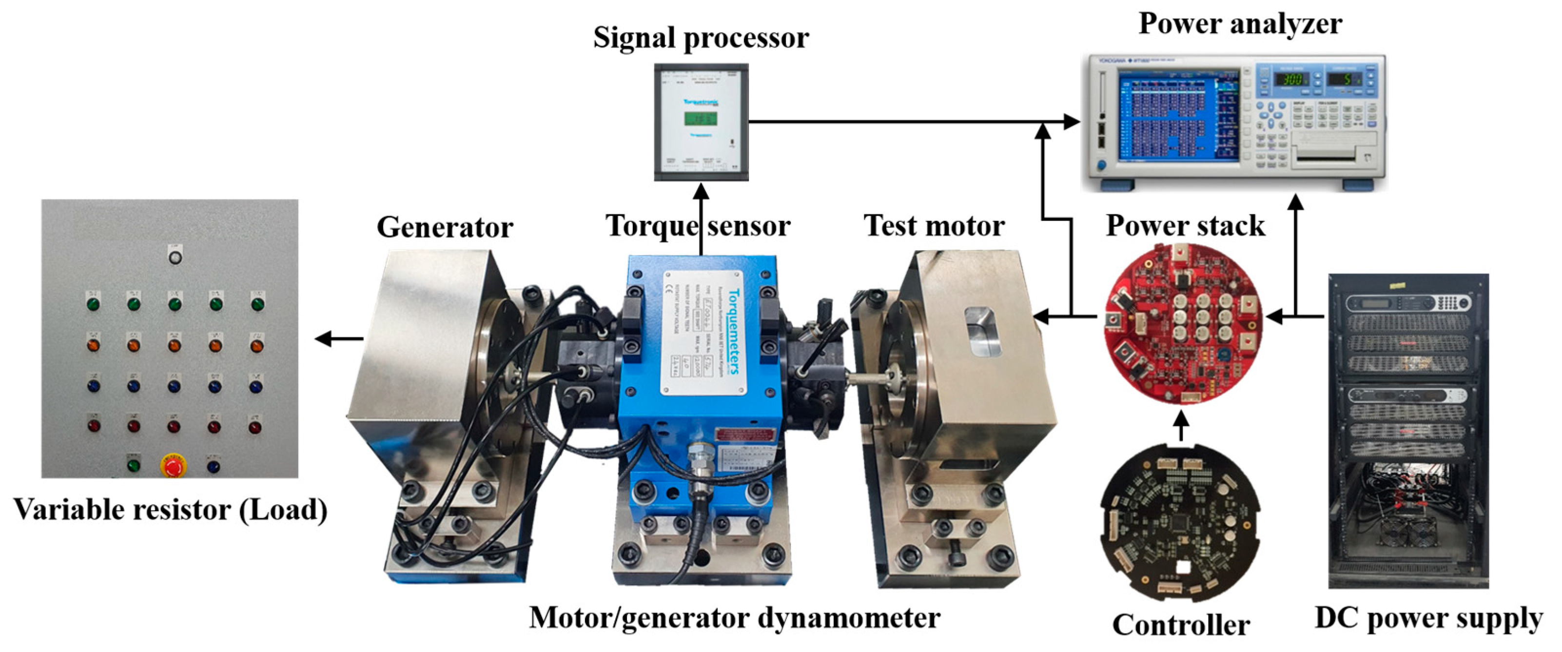
3.1. M/G Dynamometer with High-Speed Torque Sensor
3.2. Eddy Current Brake Dynamometer
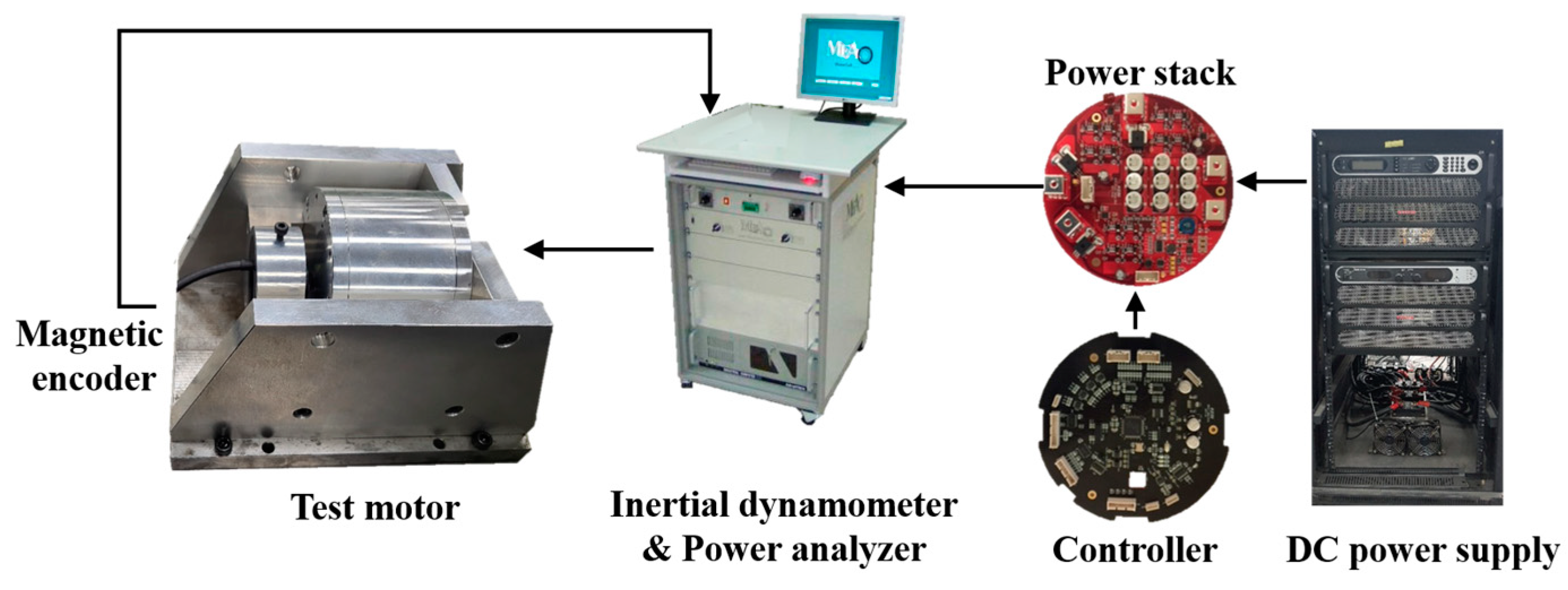
3.3. Inertial Dynamometer
4. Results of Various Experiment Methods
4.1. M/G Dynamometer with High-Speed Torque Sensor
4.2. Eddy Current Brake Dynamometer
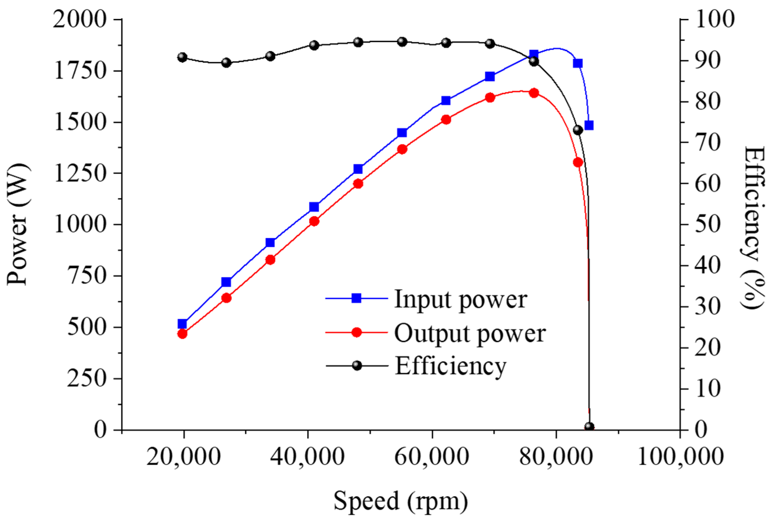
4.3. Inertial Dynamometer
4.4. Comparison of Test Results of Three Dynamometers
5. Conclusions
Author Contributions
Funding
Data Availability Statement
Acknowledgments
Conflicts of Interest
Appendix A

| Description | Specification |
|---|---|
| Engine type | Diesel |
| Displacement (L) | 1.6 |
| Bore × stroke (mm) | 76 × 88 |
| Maximum power (ps/rpm) | 115/3400~4500 |
| Maximum torque (kg-m/rpm) | 30.3/1500~2500 |
| Compression ratio | 15.5 |
| EGR system | High pressure cooled EGR system |
| After treatment system | LNT + DPF |
| Induction type | Turbocharged |
References
- Lee, W.; Schubert, E.; Li, Y.; Li, S.; Bobba, D.; Sarlioglu, B. Overview of Electric Turbocharger and Supercharger for Downsized Internal Combustion Engines. IEEE Trans. Transp. Electrif. 2017, 3, 36–47. [Google Scholar] [CrossRef]
- Lee, T.-W.; Hong, D.-K. Electrical and Mechanical Characteristics of a High-Speed Motor for Electric Turbochargers in Relation to Eccentricity. Energies 2021, 14, 3340. [Google Scholar] [CrossRef]
- Arnold, S.; Balis, C.; Barthelet, P.; Poix, E.; Samad, T.; Hampson, G.; Shahed, S.M. Garrett Electric Boosting Systems (EBS) Program; Honeywell Turbo Technologies: USA, 2005. [Google Scholar]
- Zhao, D.; Stobart, R.; Mason, B. Real-Time Energy Management of the Electric Turbocharger Based on Explicit Model Predictive Control. IEEE Trans. Ind. Electron. 2020, 67, 3126–3137. [Google Scholar] [CrossRef] [Green Version]
- Menegazzi, P.; Wu, Y.; Thomas, V. Design of an electric supercharger for downsized engines. MTZ Worldw. 2013, 74, 36–41. [Google Scholar] [CrossRef]
- Audi Technology Portal. Forced Induction Concept and Electrical System: Electric Powered Compressor (EPC) and 48-Volt Subsystem. 2016. Available online: https://www.audi-technology-portal.de/en/download?file=1416 (accessed on 18 April 2022).
- Lee, W.; Kim, J.H.; Choi, W.; Sarlioglu, B. Torque Ripple Minimization Control Technique of High-Speed Single-Phase Brushless DC Motor for Electric Turbocharger. IEEE Trans. Veh. Technol. 2018, 67, 10357–10365. [Google Scholar] [CrossRef]
- Breitbach, H.; Metz, D.; Weiske, S.; Spinner, G. Application and Design of the eBooster from BorgWarner; BorgWarner Turbo System GmbH: Auburn Hills, MI, USA, 2015. [Google Scholar]
- Biwersi, S.; Tavernier, S.; Equoy, S. Electric compressor with high-speed brushless DC motor. MTZ Worldw. 2012, 73, 50–53. [Google Scholar] [CrossRef]
- Noguchi, T.; Kano, M. Development of 150,000 r/min, 1.5 kW Permanent-Magnet Motor for Automotive Supercharger. In Proceedings of the 2007 PEDS, Bangkok, Thailand, 27–30 November 2007; pp. 183–188. [Google Scholar]
- Heidrich, T.; Ludwig, F.; Moeckel, A. Investigation of a high-speed drive for turbo-machines. In Proceedings of the Innovative Small Drives and Micro-Motor Systems, 11th GMM/ETG-Symposium, Saarbruecken, Germany, 27–28 September 2017; pp. 1–5. [Google Scholar]
- Yamashita, Y.; Ibaraki, S.; Sumida, O.; Ebisu, K.I.; An, I.L.; Ogita, I. Development of electric supercharger to facilitate the downsizing of automobile engines. Mitsubishi Heavy Ind. Tech. Rev. 2010, 47, 7–12. [Google Scholar]
- Ibaraki, S.; Yamashita, Y.; Sumida, K.; Ogita, H.; Jinnai, Y. Development of the ‘hybrid turbo’, an electrically assisted turbocharger. Mitsubishi Heavy Ind. Tech. Rev. 2006, 43, 1–5. [Google Scholar]
- Shimizu, M. Turbocharger with Electric Motor. U.S. Patent US8882478B2, 11 November 2014. [Google Scholar]
- Gödeke, H.; Prevedel, K. Hybrid turbocharger with innovative electric motor. MTZ Worldw. 2014, 75, 26–31. [Google Scholar] [CrossRef]
- Hofbauer, P. Method of Controlling an Electrically Assisted Turbocharger. U.S. Patent US20110022289A1, 27 January 2011. [Google Scholar]
- Lim, M.-S.; Kim, J.-M.; Hwang, Y.S.; Hong, J.-P. Design of an Ultra-High-Speed Permanent-Magnet Motor for an Electric Turbocharger Considering Speed Response Characteristics. IEEE/ASME Trans. Mechatron. 2017, 22, 774–784. [Google Scholar] [CrossRef]
- Gill, N. Driving clean technology. In Proceedings of the Cleantech Forum Europe 2012, Munich, Germany, 16–18 April 2012. [Google Scholar]
- Tran, H.H.; Richard, B.; Gray, K.; Hall, J.M. Developing a performance specification for an electric supercharger to satisfy a range of downsized gasoline engine applications. In Proceedings of the SAE 2016 World Congress & Exhibition, Detroit, MI, USA, 12–14 April 2016. [Google Scholar]
- Lee, T.-W.; Baek, S.-J.; Hong, D.-K.; Lee, K.-H. Simulation and Motor Test Considering Engine Experiment Validation of Electric Turbocharger for 1.6 L Diesel Engine. IEEE Trans. Transp. Electrif. 2021. [Google Scholar]
- Hong, D.-K.; Lee, T.-W.; Jeong, Y.-H. Design and Experimental Validation of a High-Speed Electric Turbocharger Motor Considering Variation of the L/D Ratio. IEEE Trans. Magn 2018, 54, 1–4. [Google Scholar]
- Hong, D.-K.; Jeong, Y.-H.; Woo, B.-C.; Kim, T.-H. Electric-mechanical performance analysis of high speed motor for electric turbo charger. Int. J. Appl. Electromagn. Mech. 2018, 57, 125–133. [Google Scholar] [CrossRef]
- Hong, D.-K.; Jeong, Y.-H. Multiphysics Analysis of a High Speed PMSM for Electric Turbo Charger. Int. J. Appl. Electromagn. Mech. 2019, 59, 835–843. [Google Scholar] [CrossRef]
- Bumby, J.R.; Spooner, E.; Jagiela, M. Equivalent circuit analysis of solid-rotor induction machines with reference to turbocharger accelerator applications. IEE Proc.-Electr. Power Appl. 2006, 153, 31–39. [Google Scholar] [CrossRef]
- Gerber, M.; Gilson, A.; Depernet, D.; Dubas, F.; Espanet, C.; Andrieux, G. Coupled Electronic and Magnetic Fast Simulation for High-Speed Permanent-Magnet Drive Design. In Proceedings of the IEEE Vehicle Power and Propulsion Conference (VPPC), Hangzhou, China, 17–20 October 2016. [Google Scholar]
- Jung, D.-H.; Lee, J.-K.; Kim, J.-Y.; Jang, I.S.; Lee, J.; Lee, H.-J. Design Method of an Ultrahigh Speed PM Motor/Generator for Electric-Turbo Compounding System. IEEE Trans. Appl. Supercond. 2018, 28, 1–4. [Google Scholar] [CrossRef]
- Farhan, A.; Johnson, M.; Hanson, K.; Severson, E.L. Design of an Ultra-High Speed Bearingless Motor for Significant Rated Power, In Proceedings of the 2020 IEEE Energy Conversion Congress and Exposition (ECCE), Detroit, MI, USA, 11–15 October 2020.
- Ou, J.; Liu, Y.; Doppelbauer, M. Comparison Study of a Surface-Mounted PM Rotor and an Interior PM Rotor Made From Amorphous Metal of High-Speed Motors. IEEE Trans. Ind. Electron. 2021, 68, 9148–9159. [Google Scholar] [CrossRef]
- Ou, J.; Liu, Y.; Breining, P.; Gietzelt, T.; Wunsch, T.; Doppelbauer, M. Experimental Characterization and Feasibility Study on High Mechanical Strength Electrical Steels for High-Speed Motors Application. IEEE Trans. Ind. Appl. 2021, 57, 284–293. [Google Scholar] [CrossRef]
- IEC 60034-2-1; Rotating Electrical Machines—Part 2-1: Standard Methods for Determining Losses and Efficiency from Tests (Excluding Machines for Traction Vehicles). International Electrotechnical Commission: Geneva, Switzerland, 2014.
- IEEE Std 115™; IEEE Guide for Test Procedures for Synchronous Machines Including Acceptance and Performance Testing and Parameter Determination for Dynamic Analysis. IEEE: Piscataway, NJ, USA, 2019.
- van Millingen, R.D.; van Millingen, J.D. Phase shift torquemeters for gas turbine development and monitoring, In Proceedings of the ASME 1991 International Gas Turbine and Aeroengine Congress and Exposition, Orlando, FL, USA, 3–6 June 1991.
- ANSI/API Standard 610; Centrifugal Pumps for Petroleum, Petrochemical and Natural Gas Industries. American Petroleum Institute: Washington, DC, USA, 2004.
- API Publication 684; Tutorial on the API Standard Paragraphs Covering Rotor Dynamics and Balancing: An Introduction to Lateral Critical and Train Torsional Analysis and Rotor Balancing. American Petroleum Institute: Washington, DC, USA, 1996.


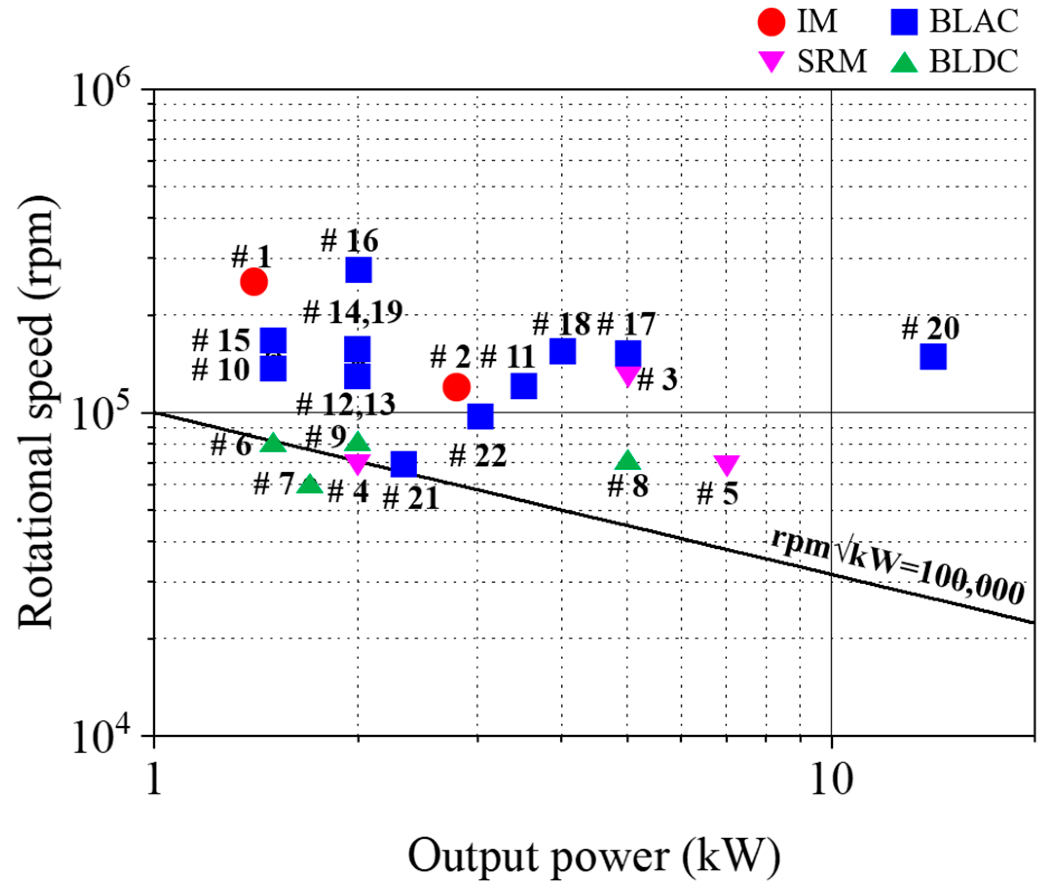
| No. | Motor | Power (kW) | Speed (krpm) | Voltage (Vdc) | Topology | Designed/Studied by |
|---|---|---|---|---|---|---|
| 1 | IM | 1.4 | 250 | 12 | EAT | Honeywell |
| 2 | 2.8 | 120 | 48 | EAT | Honeywell | |
| 3 1 | SRM | 5.0 | 140 | 12/24 | EAT | Loughborough Univ. |
| 4 | 2.0 | 70 | 12 | TEDC | Valeo/CPT | |
| 5 2 | 7.0 | 70 | 48 | TEDC | Valeo/CPT | |
| 6 | BLDC | 1.5 | 80 | 24 | TEDC | WEM-PEC |
| 7 | 1.7 | 60 | 12 | TEDC | BorgWarner | |
| 8 3 | 5.0 | 70 | 48 | TEDC | BorgWarner | |
| 9 | 2.0 | 80 | 48 | TEDC | MMT | |
| 10 | BLAC | 1.5 | 150 | 12 | EC | Nagaoka Univ. |
| 11 | 3.5 | 120 | 48 | EC | Technische Univ. | |
| 12 | 2.0 | 140 | 12 | EC | MHI | |
| 13 | 2.0 | 140 | 12 | EAT | MHI | |
| 14 | 2.0 | 150 | 12 | EAT | IHI | |
| 15 | 1.5 | 160 | 12 | EAT | G + L innotec | |
| 16 | 2.0 | 280 | 12 | EAT | EcoMotor | |
| 17 | 5.0 | 150 | 48 | EAT | EcoMotor | |
| 18 | 4.0 | 150 | 48 | EAT | Hanyang Univ. | |
| 19 | 2.0 | 150 | 12 | EAT | Aeristech | |
| 20 | 14.0 | 150 | 48 | EAT | Aeristech | |
| 21 | 2.3 | 70 | 48 | TEDC | KERI/Keyyang | |
| 22 | 3.0 | 100 | 48 | TEDC | KERI/Keyyang |
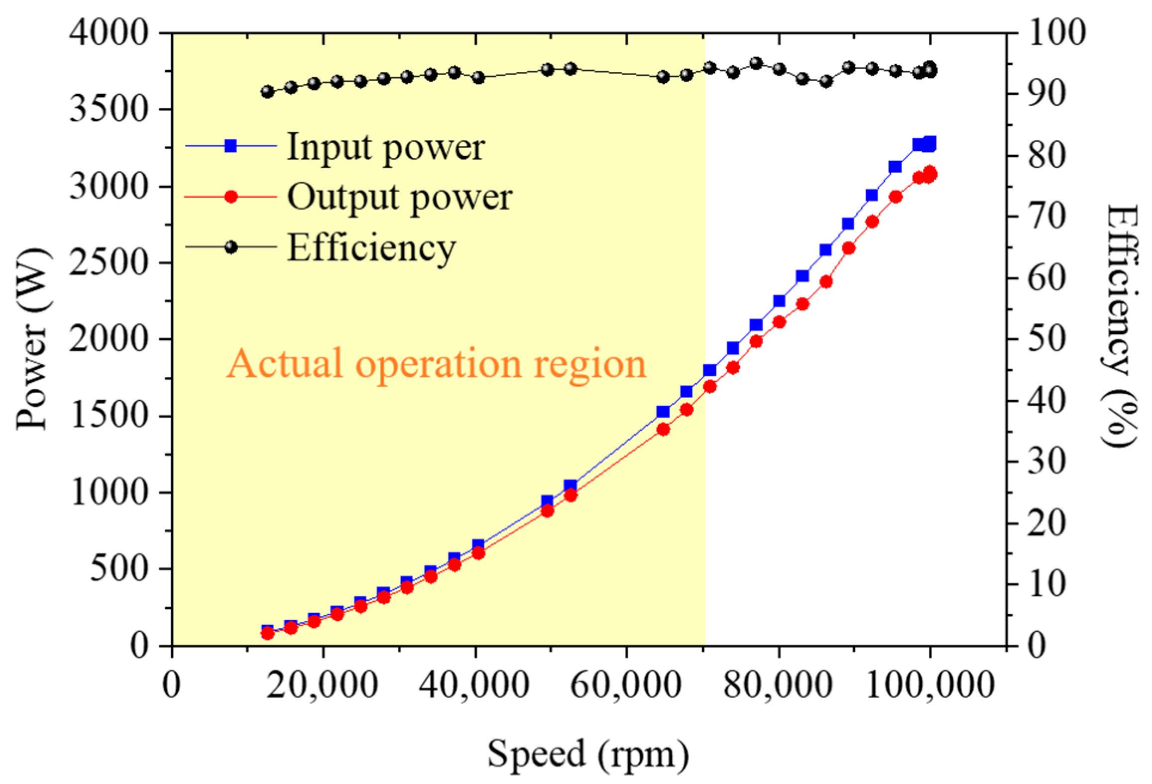
| Parameter | Specification | FEA | Experiment |
|---|---|---|---|
| Torque (Nm) | 0.2865 | 0.2865 | 0.2946 |
| Power (kW) | 3 | 3 | 3.084 |
| Speed (rpm) | 100,000 | 100,000 | 100,030 |
| Efficiency (%) | ≥93 | 94.0 | 94.10 |
| Torque ripple (%) | - | 1.32 | - |
| Rotor core loss (W) | - | 4.09 | - |
| Stator core loss (W) | - | 51.7 | - |
| PM loss (W) | - | 6.07 | - |
| Winding loss (W) | - | 55.7 | - |
| Mechanical loss (W) | - | 75.0 | - |
| Item | FEA | Reference (Figure 4) | M/G | Eddy Current Brake | Inertial | |
|---|---|---|---|---|---|---|
| Output power (kW) | 70,000 rpm | 1.70 | 1.70 | 1.722 | - | 1.626 |
| 60,000 rpm | 1.30 | 1.30 | 1.327 | 1.321 | 1.472 | |
| Efficiency (%) | 70,000 rpm | 93.74 | 94.2 | 93.3 | - | 93.8 |
| 60,000 rpm | 93.68 | 93.7 | 93.0 | 93.7 | 93.8 | |
Disclaimer/Publisher’s Note: The statements, opinions and data contained in all publications are solely those of the individual author(s) and contributor(s) and not of MDPI and/or the editor(s). MDPI and/or the editor(s) disclaim responsibility for any injury to people or property resulting from any ideas, methods, instructions or products referred to in the content. |
© 2023 by the authors. Licensee MDPI, Basel, Switzerland. This article is an open access article distributed under the terms and conditions of the Creative Commons Attribution (CC BY) license (https://creativecommons.org/licenses/by/4.0/).
Share and Cite
Lee, T.-W.; Hong, D.-K. Performance Validation of High-Speed Motor for Electric Turbochargers Using Various Test Methods. Electronics 2023, 12, 2937. https://doi.org/10.3390/electronics12132937
Lee T-W, Hong D-K. Performance Validation of High-Speed Motor for Electric Turbochargers Using Various Test Methods. Electronics. 2023; 12(13):2937. https://doi.org/10.3390/electronics12132937
Chicago/Turabian StyleLee, Tae-Woo, and Do-Kwan Hong. 2023. "Performance Validation of High-Speed Motor for Electric Turbochargers Using Various Test Methods" Electronics 12, no. 13: 2937. https://doi.org/10.3390/electronics12132937