Article

Search-Coil Based Stator Interturn Fault Detection in Permanent Magnet Machines Running under Dynamic Condition

National Key Laboratory of Electromagnetic Energy, Naval University of Engineering, Wuhan 430030, China
*
Author to whom correspondence should be addressed.
Electronics 2023, 12(13), 2827; https://doi.org/10.3390/electronics12132827
Submission received: 6 May 2023 / Revised: 15 June 2023 / Accepted: 21 June 2023 / Published: 26 June 2023

Abstract

:
Interturn short circuit (ITSC) fault is a common fault in electric machines, which may severely damage the machines if no protective measure is taken in time. There are numerous fault diagnosis methods under a steady-state condition. However, there is relatively limited research on fault diagnosis under dynamic conditions. The dynamic operation of motors, such as in electric cars, is a very common scenario. Hence, this paper proposes a search-coil based online method for detecting ITSC fault in permanent magnet synchronous machine (PMSM) under a dynamic condition. The search coils are placed on the stator circumference at equal intervals. Each search coil reflects the information about the magnetic field in its vicinity and also contains the fault information. In this paper, the voltage induced by the odd sideband harmonics around the even carrier (2ωc±ω0) is selected as the fault characteristic to be used in effectively improving the detected signal-to-noise ratio by excluding the interference of the counter-potential of the permanent magnet. Since two adjacent search coils are placed one pole apart, a set of quadrature signals can be acquired. The Digital Lock-In Amplifier (DLIA) technology is applied to extract the amplitude of the characteristic voltage, which overcomes the shortcomings of the traditional spectrum analysis in applying to non-stationary conditions. The amplitudes of the voltage at different search coils can be compared to further determine the occurrence of a fault and also its rough location if occurred. Experiments were conducted with a six-phase PMSM for demonstrating the effectiveness of the proposed method. The obtained results show that the proposed method can accurately determine the occurrence of a fault.

1. Introduction

Permanent magnet synchronous machines are employed widely in modern industries, e.g., electric vehicles and wind power generators, due to its high efficiency and high torque density [1,2]. However, according to industrial surveys [3], the stator winding failure is one of the most common failures, usually starting with an ITSC fault between adjacent turns of the stator winding. A large circulating current flows in the shorted turns, thus overheating or even melting the insulations of the adjacent turns [4].
A typical ITSC fault may be triggered by insulation aging, overvoltage shock, mechanical vibration, and many other agents. In the initial stage of the ITSC fault, the number of short-circuit turns is usually small and the contact resistance at the short-circuit point is large. At this stage, the short-circuit current flowing through the short-circuit point is relatively small, and the impact of the fault on the stator current and internal magnetic field of the motor is also small. So, the motor can still continue to run. However, if the initial ITSC fault is not diagnosed and the required corrective measures are not taken in time, the short-circuit current will continuously generate a large amount of heat at the short-circuit point, which will likely further damage the insulation near the short-circuit point, and make the fault aggravate and spread, forming a vicious circle [5]. A severe ITSC fault may not only seriously affect the performance of the motor, but may also lead to the failure of the entire motor system. In addition, an ITSC fault may also weaken the magnetic field near the point of failure, which may cause other more difficult-to-repair failures, such as demagnetization failures.
Various diagnostic methods for detecting ITSC fault have been proposed from time to time, which can be divided into three categories: signal-based, model-based, and data-driven-based methods [6,7,8,9,10].
The first approach uses the frequency spectrum analysis, such as the fast Fourier transform (FFT) [11,12], short-time Fourier transform, (STFT) [13], wavelet transform (WT) [14,15], and Hilbert–Huang transform (HHT) [16] to analyze phase current signals. The ITSC fault can be diagnosed by analyzing the characteristic harmonics in the stator current. The conventional method of FFT represents information in the frequency domain, which means the losing of a series of events, such as speed variation and variable load. Note that the fault harmonic components appearing in the stator current spectrum highly depend on the configuration of the stator winding [17]. STFT uses a window function to overcome the tradeoff between time and frequency resolution. However, a fixed length of window may result in an inconsistent treatment of different current frequencies [18]. WT is capable decomposing non-stationary and wideband signals in the time domain into steady-state and transitory parts in the time-frequency domain [19], while it is difficult to choose a suitable wavelet basis function. HHT was introduced by Huang to overcome the many limits of WT [20]. However, this transform also has some limitations. The patterns obtained by HHT are less clear compared to those obtained by DWT. A more important limitation is that HHT is usable only for extracting frequency-time distribution over narrow-band signals.
The model-based approach usually selects negative/zero-sequence current, impedance, voltage, and other characteristics [6,21,22,23], so as to build a fault indicator. However, as machine parameters, such as the winding resistance and inductance, always vary with working conditions, it is difficult to ensure the accuracy of the employed theoretical model.
The data-driven-based methods can take the training data as the benchmark to automatically identify the type of fault and severity of the input data [24,25]. It is widely applied to identify the underlying knowledge related to the features of the fault. However, it is very difficult to collect a sufficient amount of data under healthy and faulty conditions to sufficiently train these models.
The approach, developed based on search coils (SCs), can directly observe the change in the magnetic field of the motor, which can greatly improve the sensitivity. Because of this as well, it has received the attention of many scholars despite being an invasive detection method [26,27,28,29]. Da [27] used the low-frequency components of the voltage signal of an SC, so that its feature is not obvious and the operating condition of the motor influences the diagnosis. Chong [30] selected the pulse width modulation (PWM) harmonic signal as the fault feature with better sensitivity. Huang [31] proposed a strategy based on the negative-sequence components of the second carrier frequency sideband harmonics in the voltage signal of the SC. Selecting this frequency component as the fault characteristic is not only more obvious than the fundamental component used in the traditional SC methods, but can also be transformed into a DC indicator by two coordinate transformations, which would be conducive to the online implementation in both stationary and non-stationary conditions. However, this diagnostic algorithm requires additional information about the position of the rotor.
On the basis of above, a novel ITSC fault diagnostic method for PMSM based on SCs is proposed in this article. Compared with the existing methods, it shows several good features during experimental tests on a PMSM.
(1)
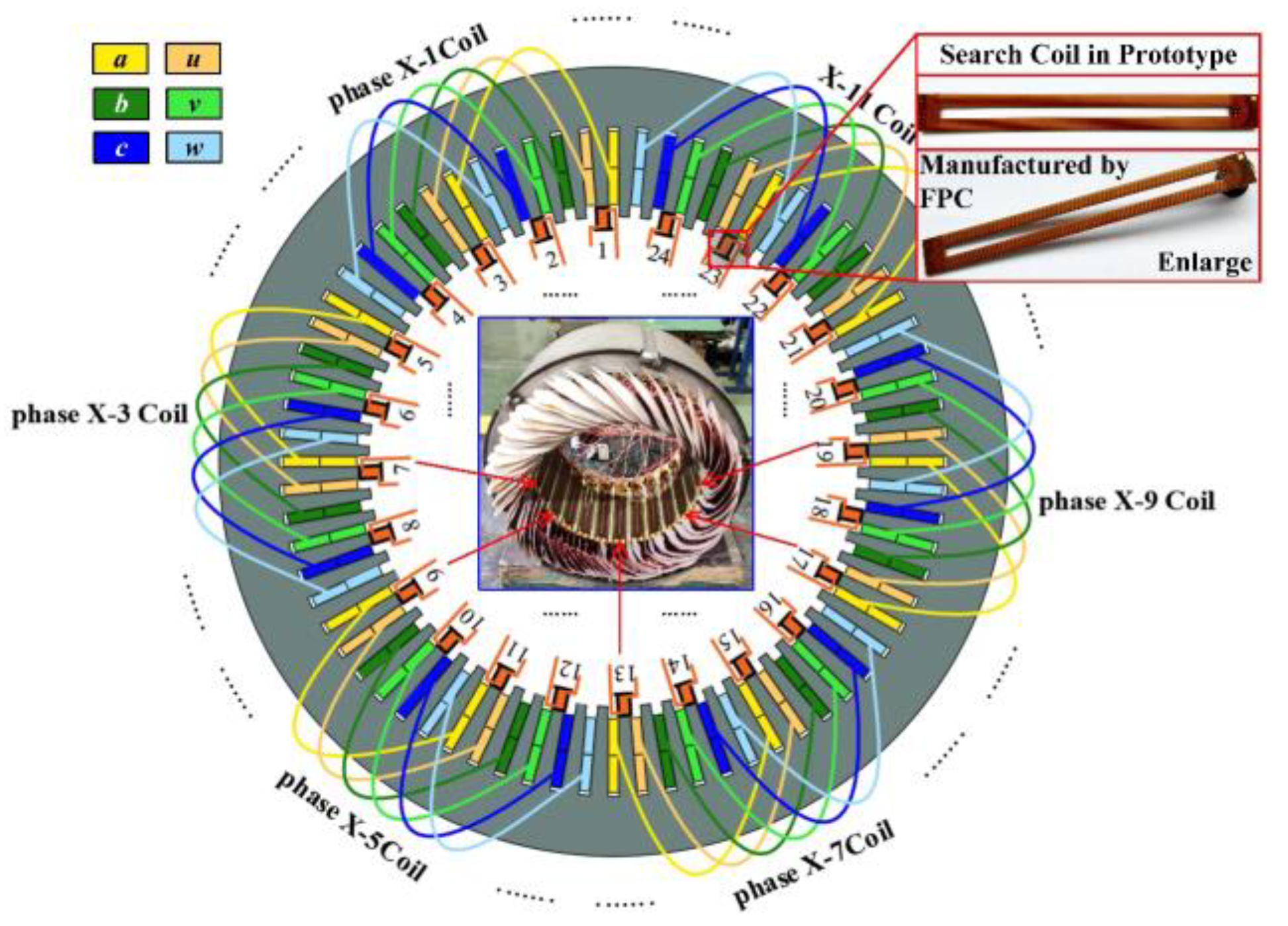
Flexible PCB is used to make search coils, and the number of turns can be increased if the full rate of the slot is certain, and increased mutual inductance makes it easier to detect fault signals.
(2)
A demodulation algorithm based on the Digital Lock-In Amplifier (DLIA) is proposed, which can be used under non-stationary conditions.
(3)
The voltage at the characteristic frequency of the search coil is standardized and its variance is considered as the fault characteristic quantity, which can make robust detection of motor speed.
The rest of this article is organized as follows. In Section 2, the proposed method is theoretically analyzed in detail. In Section 3, the proposed fault detection method is validated by simulation. In Section 4, the experiments are conducted and the obtained results are analyzed. Finally, Section 5 concludes this article.

2. Principle of Proposed Method

In this section, the proposed method is theoretically analyzed in detail. Initially, the ITSC fault in a six-phase equivalent circuit model is analyzed. Following this analysis, the extraction method of voltage amplitude at a characteristic frequency under variable operating conditions is proposed.

2.1. Back EMF in Search Coils

The back EMF in the search coils is generated by the armature winding and permanent magnets mounted on the rotor, which can be represented as follows:
u s c = M p s d d t i + ψ f F θ
where Mps, i, ψf, θ, and F(θ) are the mutual inductance of phase winding and search coils, phase current, amplitude of permanent magnet flux, angular position of rotor, and unit flux linkage of search coils, respectively. The second part of Equation (1) remains unchanged, while the phase current, and mutual inductance of phase winding and search coils change with variations in EMF when ITSC fault occurs.

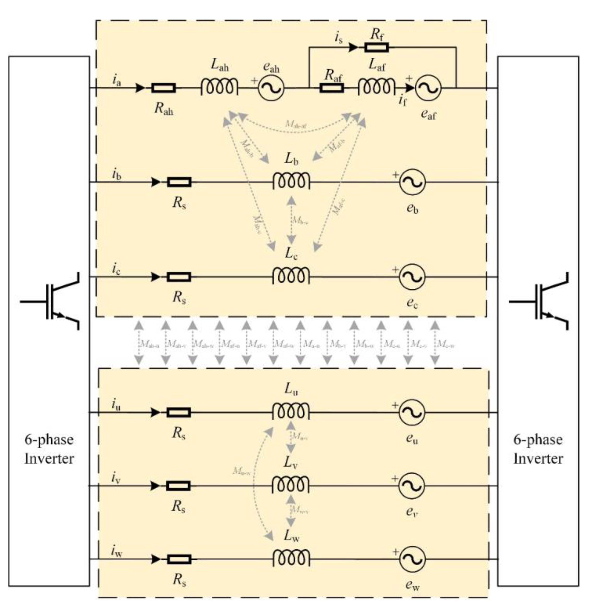
2.2. Six-Phase Equivalent Circuit Model with ITSC Fault

The three-phase equivalent circuit model was introduced in Refs. [21,32]. The equivalent circuit model of the stator winding in the absence of fault can be expressed by Equation (2).
u = R i + d d t ψ
where
ψ = L i + ψ f F θ e
F θ e = cos θ e cos θ e 2 π 3 cos θ e + 2 π 3 cos θ e π 6 cos θ e 5 π 6 cos θ e + π 2 T
R = R s I 6 × 6
Substituting Equation (3) into Equation (2), one can get:
u = R i + L d d t i + ψ f ω e d d θ e F θ e
It can be seen that the main component of the voltage in a search coil is induced by the permanent magnet, as expressed by Equation (1), while the MMF field contains only the main components, such as the fundamental frequency and the third. In PWM-powered motors, the armature winding contains the harmonic component around the even carrier, which is independent of the MMF field. Therefore, the harmonic at the switching frequency is selected as the fault detection characteristic, which can be expressed by Equation (6).
u h = R i h + L d d t i h
u h = u h a 1 u h b 1 u h c 1 u h a 2 u h b 2 u h c 2 T
u h a 1 = a 1 cos 2 π f h t + ϕ u h b 1 = a 1 cos 2 π f h t + ϕ + 2 π 3 u h c 1 = a 1 cos 2 π f h t + ϕ 2 π 3 u h a 2 = a 1 cos 2 π f h t + ϕ + π 6 u h b 2 = a 1 cos 2 π f h t + ϕ + 5 π 6 u h c 2 = a 1 cos 2 π f h t + ϕ π 2
where a1, ϕ, and fh are the amplitude, initial phase angle and frequency of voltage. G. Holmes [33] analyzed the voltage components under PWM supply. In case of a naturally sampled reference and double-edge carrier, the voltage can be expressed as:
u a = U d c M cos ω 0 t + 4 U d c π m = 1 n = 1 2 m J 2 n 1 m π M cos m + n 1 π cos 2 m ω c t + 2 n 1 ω 0 t
where Udc, M, ω0, ωc and Jx are the DC bus voltage, voltage modulation ratio, fundamental wave angular frequency, carrier angular frequency, and Bessel function. Note that a1 in Equation (9) can be calculated by taking m = n = 1 in Equation (10).
a 1 = 2 U d c π J ± 1 π M cos ± π cos 2 ω c t ± ω 0 t
The voltage spectrum of phase a is shown in Figure 1, where the sideband harmonics near the switching frequency (2ωc ± ω0) is selected as the characteristic frequency.
Note that ω0 is a variable under the variable operating conditions, which also means that the spectrum in Figure 1 changes as the operating conditions change. Because of this, the conventional spectrum analysis methods are no longer applicable.
The six-phase equivalent circuit model with ITSC fault in Phase a is shown in Figure 2, where the equivalent circuit model of the stator winding can be described as Equation (12).
u h F = R F i h F + L F d d t i h F
where
u h F = u a u b u c u u u v u w 0 T
R F = R A 0 0 0 0 0 R F 0 R B 0 0 0 0 0 0 0 R C 0 0 0 0 0 0 0 R U 0 0 0 0 0 0 0 R V 0 0 0 0 0 0 0 R W 0 R f 0 0 0 0 0 R F + R f
L F = [ L A A F M A B F M A C F M A U F M A V F M A W F M A F F M A B L B B M B C M B U M B V M B W M B F M A C M B C L C C M C U M C V M C W M C F M A U M B U M C U L U U M U V M U W M U F M A V M B V M C V M U V L V V M V W M V F M A W M B W M C W M U W M V W L W W M W F M A F M B F M C F M U F M V F M W F L F F ]
L A A F = L A A + M A F
M A B F = M A B + M B F
Equation (1) can be rewritten as follows by considering only the high frequency component in the fault state:
u s c F = M p s F d d t i h F
where Mpsf and i h F are the mutual inductance matrices between the phase windings and search coils and the high frequency component of phase current, respectively.
From Equations (12), (14), (15), and (18), it can be seen that when a ITSC fault occurs, the mutual inductance matrix between the motor phase windings and search coils as well as high-frequency current component in the phase winding changes. Therefore, the corresponding high-frequency induced voltage component in the search coils also changes.

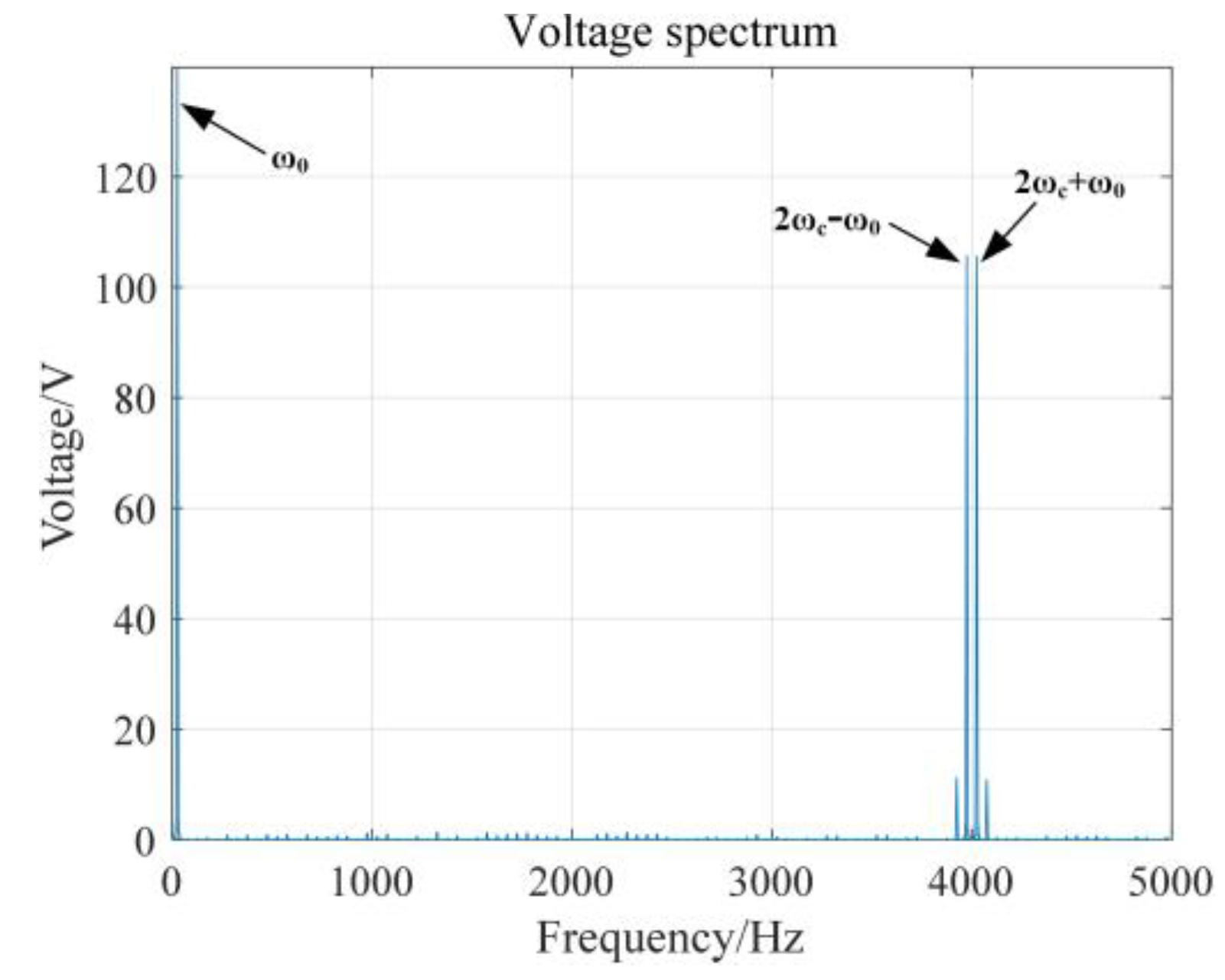
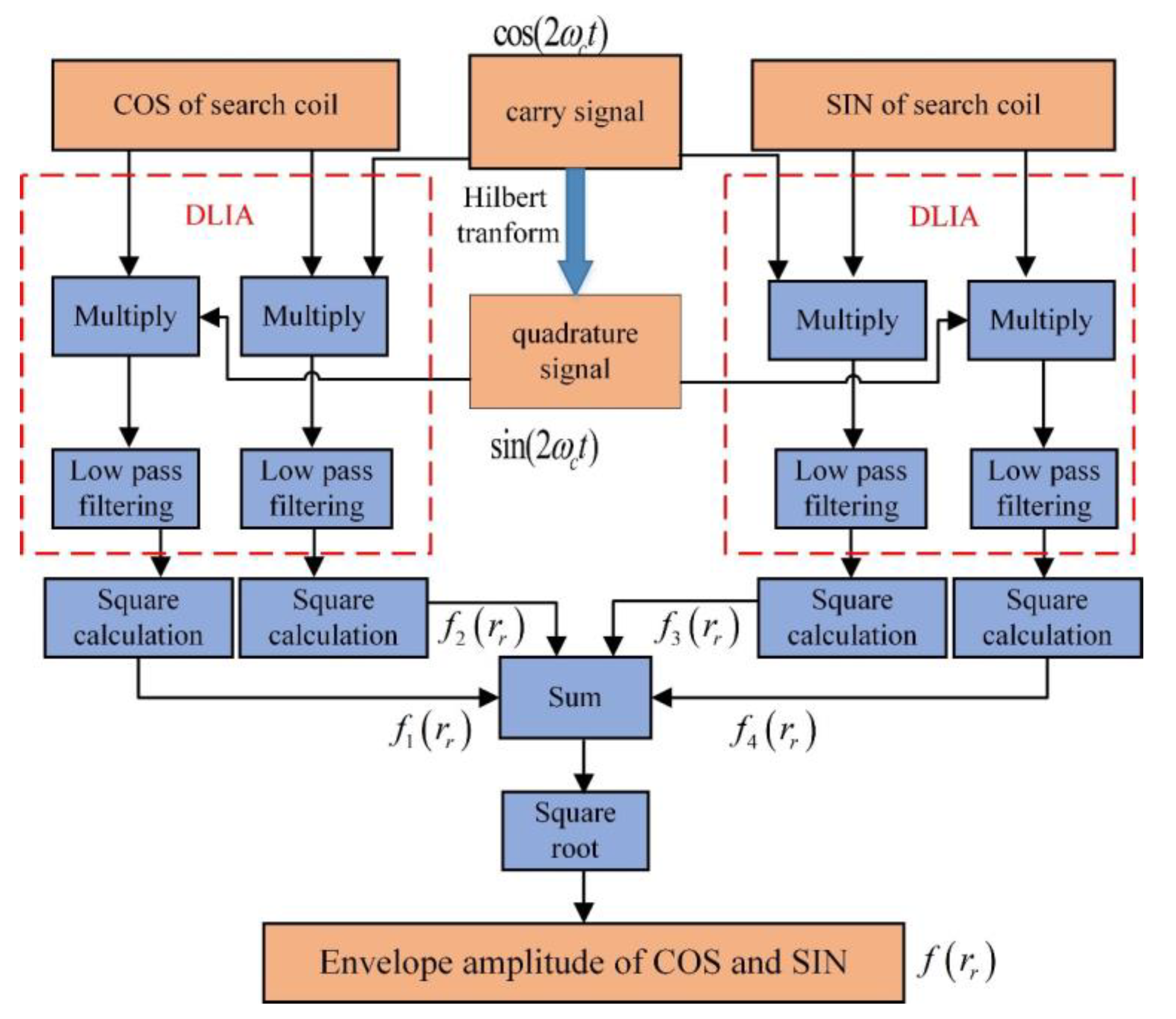
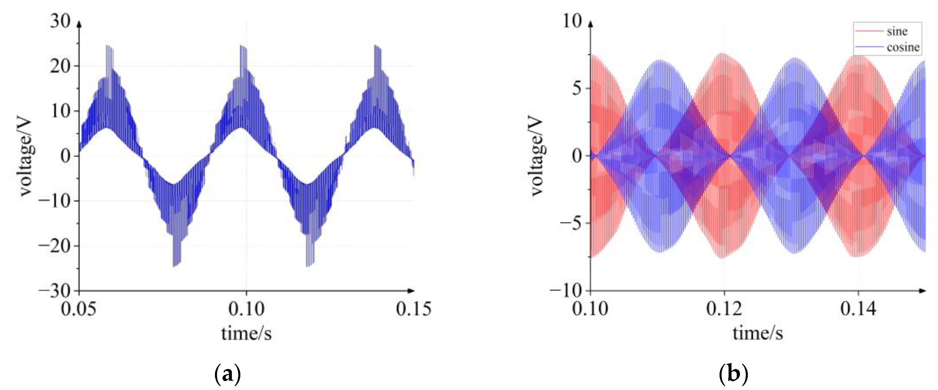
2.3. Method for Estimating Voltage Amplitude

From Equation (10), the high frequency voltage component in the phase winding is the result of modulation by the inverter switching frequency, so that the same frequency component in the search coils will exist. The conventional spectrum analysis methods are no longer effective under dynamic conditions as the electrical fundamental frequency changes. A demodulation algorithm based on DLIA is proposed to tackle this problem.
The scheme is shown in Figure 3.
(1)
Multiply the original signal by two quadrature reference signals at the carrier frequency;
(2)
Obtain the signal envelope by low-pass filtering;
(3)
Obtain the amplitude by the two envelopes of sine and cosine.

3. Validation through Simulation

The proposed fault detection method is first validated by simulation. The subject used in the experiments is a surface-mounted permanent magnet synchronous motor (PMSM). The main parameters of the studied PMSM are listed in Table 1 and the detailed parameters are shown in Table A1.
Co-simulation with SIMPLORER and Maxwell used to consider core saturation and closed-loop control effects, is shown in Figure 4. The main function of SIMPLORER is to adjust the model input according to the reference speed and the actual load torque, while 2D FEM module calculates the output of the motor in terms of current, torque, rotor position, etc., at each time step for a given input. Finally, the cycle of two iterations forms a complete closed-loop control.

3.1. Search Coil Arrangement Scheme

The search coils are used to sense the information about the magnetic field in the air gap to reflect the motor condition. In order to prevent any damage to the search coils during the wiring process of the motor winding, the search coils are usually arranged at the slot after it has been wired down. In addition, the object of this paper is a six-phase whole-pitch concentric winding motor that has six pitches. The demodulation scheme of the characteristic signal proposed in this paper requires the orthogonal arrangement of two adjacent detection coils. The research prototype is a 12-pole and 72-slot PMSM, which means that the number of search coils may be 24, 12, 8, or 4. Each phase winding consists of several coil units in series and the ITSF is a local fault. Therefore, in order to more accurately detect whether a fault occurs, the paper finally selected 24 search coils, as shown in Figure 5, where X represents phases a, b, c, u, v, and w, each of which consists of 12 unit-windings connected in series.

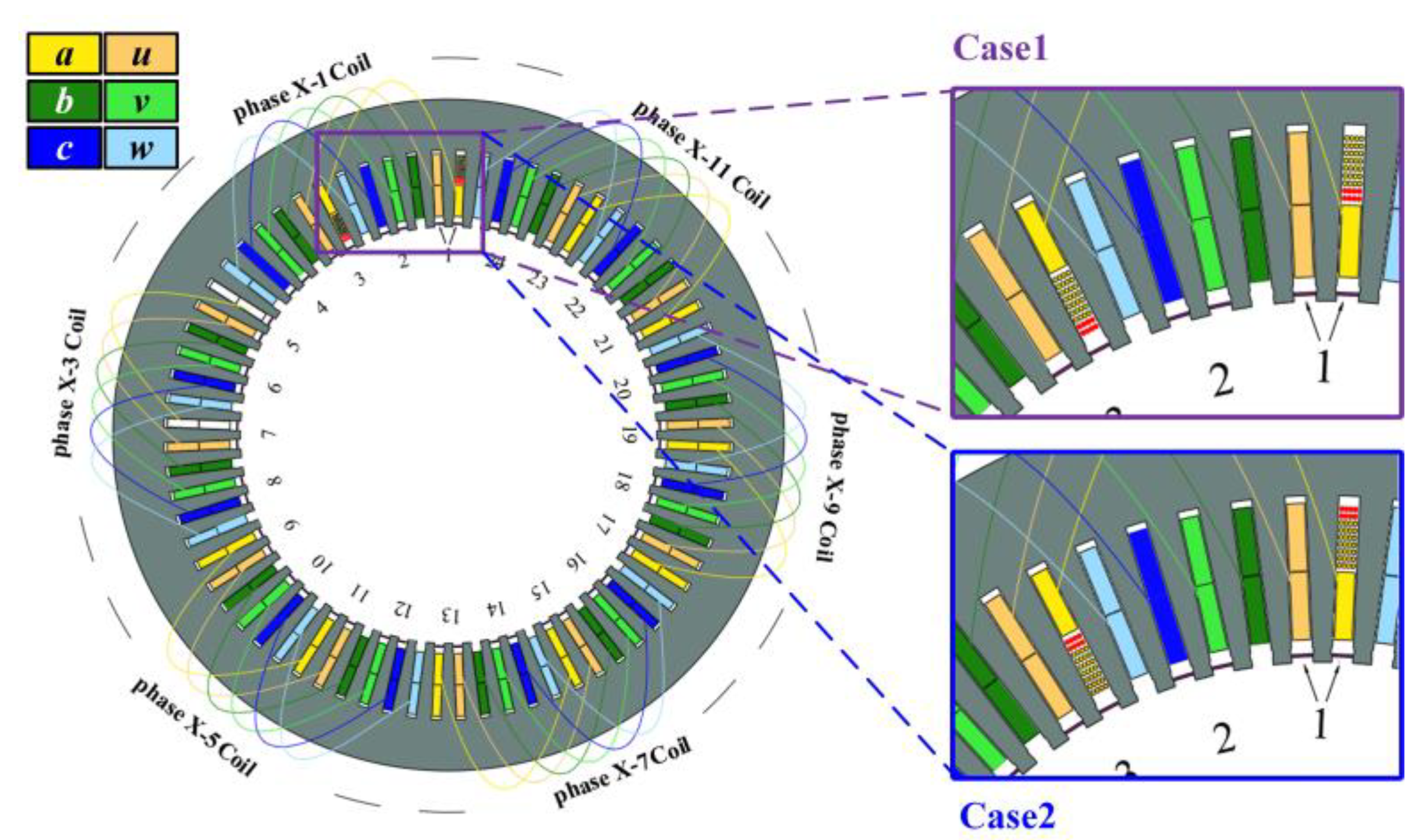
3.2. Precise Modeling for Analyzing Impact of Fault Location

The prototype uses a concentric winding with a double-layer, where the number of conductors per slot is 72. It is necessary to analyze the influence of the location of the fault on the test results for this type of loose wires.
The modeling and profiling of each conductor in Maxwell are shown in Figure 6, where the two figures on the right side are the finite element models of two different fault locations under an eight-turn short circuit. The obtained simulation results show that the mutual inductance matrix between each winding and search coil remains constant when considering different locations of the fault in the same slot, as reported in Table 2, where the maximum amount of variation is 0.21956%, and af is the fault part winding of phase a. So, it is seen that no distinction can be made between the fault locations in the same slot.

3.3. Simulation Results
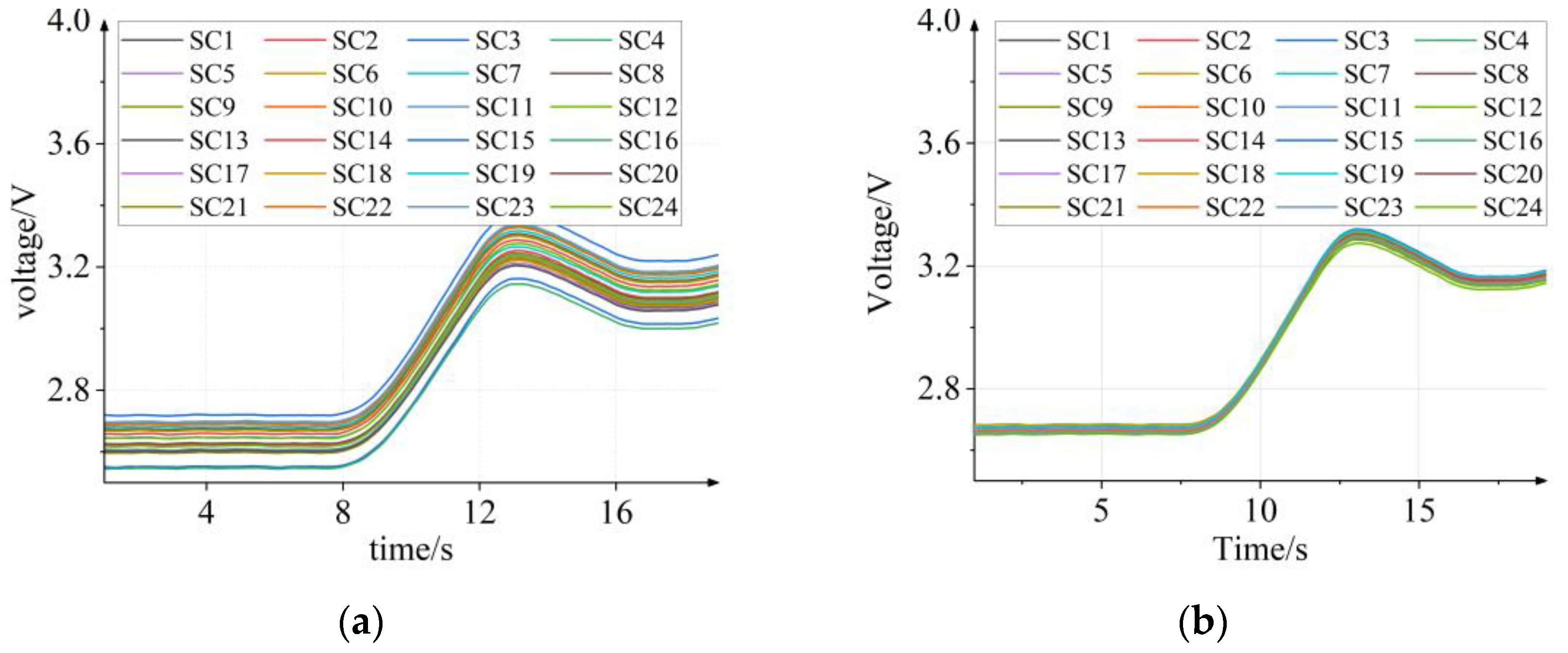
Take No. 1 search coil as an example. Its induced voltage contains the fundamental frequency component and the PWM harmonic component. The simulation waveform is shown in Figure 7a. Since the proposed scheme focuses only on the PWM harmonic component, the original signal is band-pass filtered, as shown in Figure 7b.

3.3.1. DLIA

The induced voltage acquired by the search coil contains not only the corresponding component of the armature winding through mutual inductance but also the induced electromotive force generated by the rotor permanent magnet. According to the previous analysis, the selection of the high-frequency signal as a characteristic quantity is more advantageous in terms of sensitivity as well as signal-to-noise ratio. In addition, the low frequency component of the signal is mainly the electrical fundamental frequency and its multiples, while the high frequency component is the switching sub-harmonics generated by PWM. These two can be easily distinguished. Therefore, band-pass filtering can be performed before applying DLIA to the signal. The results of filtering the signal acquired by No. 1 search coil (SC1) is shown in Figure 7b.
Since two adjacent search coils are arranged one pole apart, their two signals are orthogonal to each other, as shown Figure 7b.
The amplitude of the characteristic components in the 24 coils can be obtained by processing 2 adjacent orthogonal signals, as shown in Figure 3. The amplitude of the characteristic quantity calculated during the increase of the motor speed from 100 rpm to 120 rpm is shown in Figure 8a, where Figure 8b shows the change in the rotational speed.

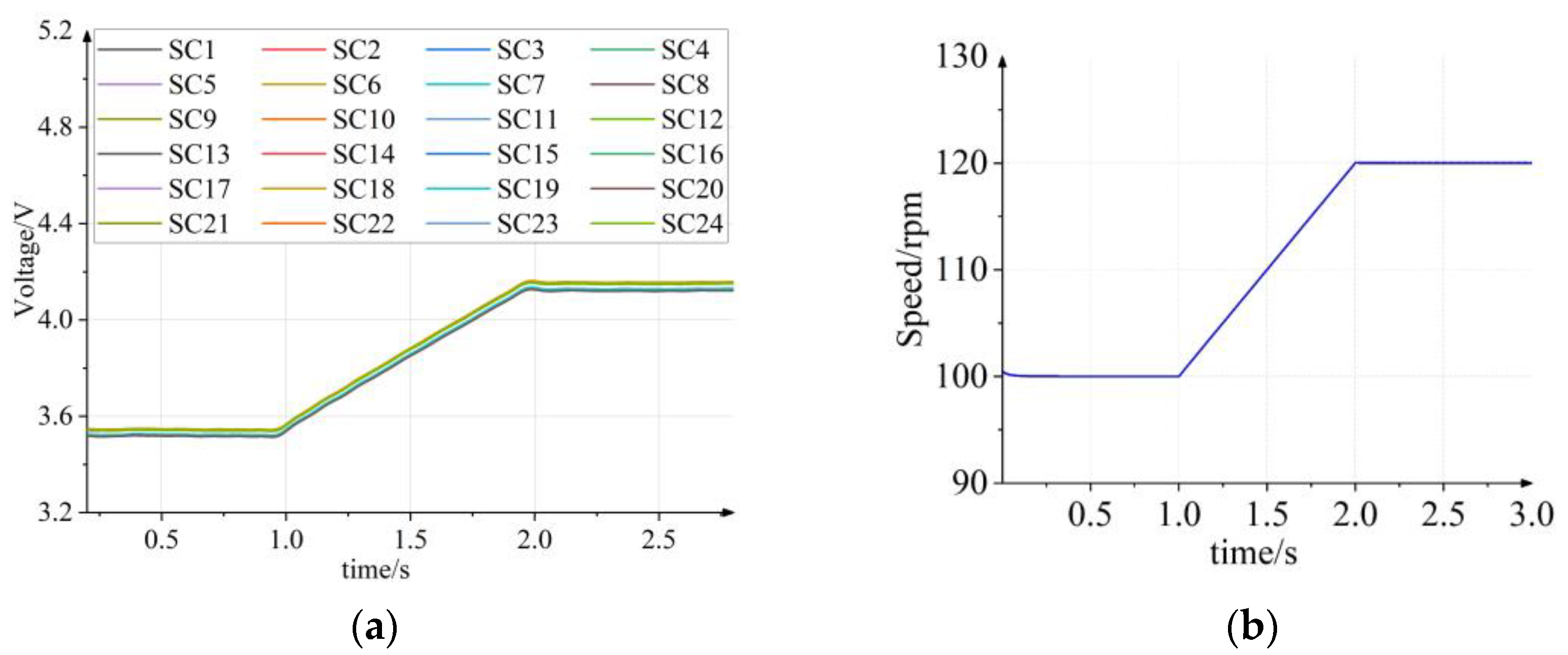
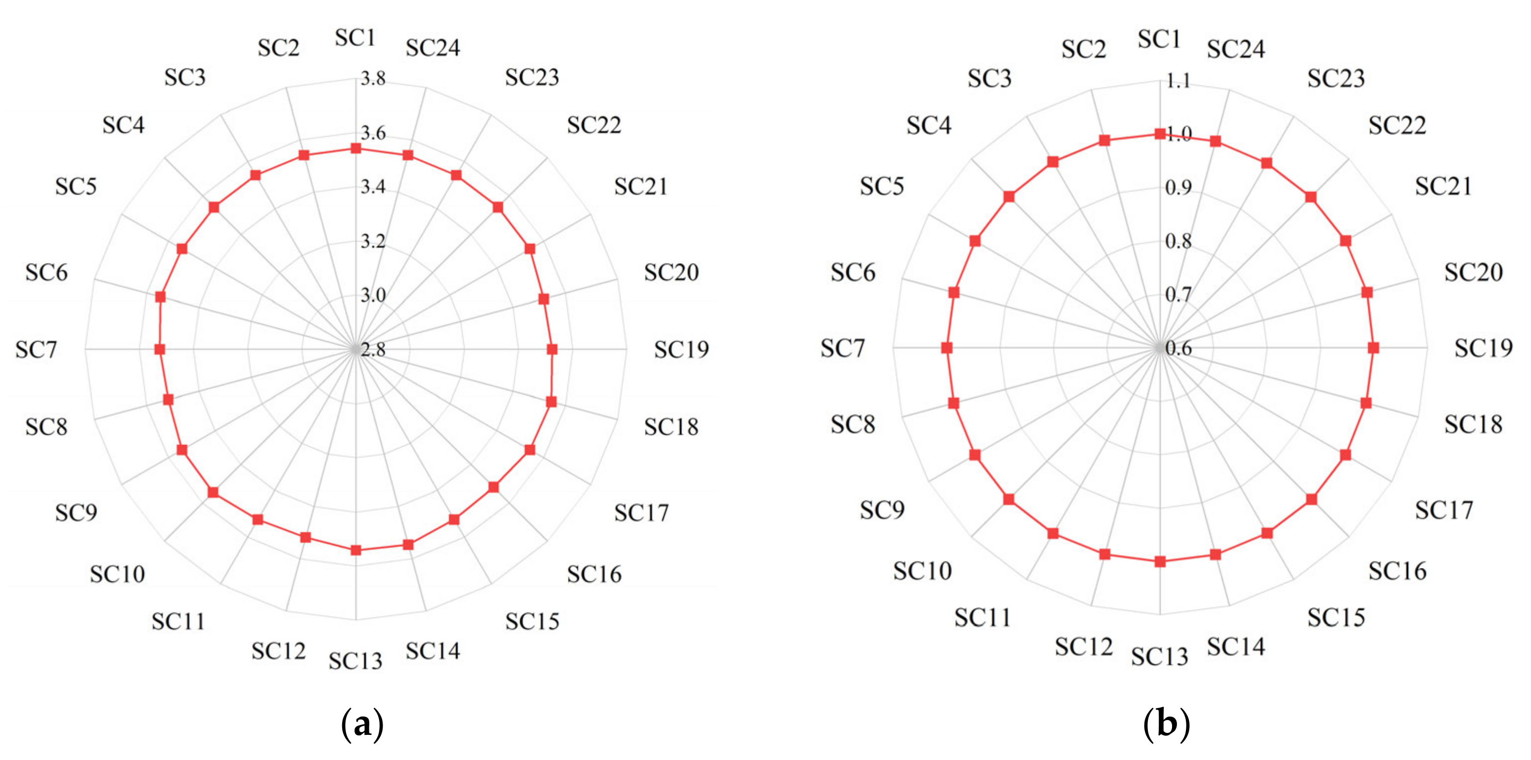
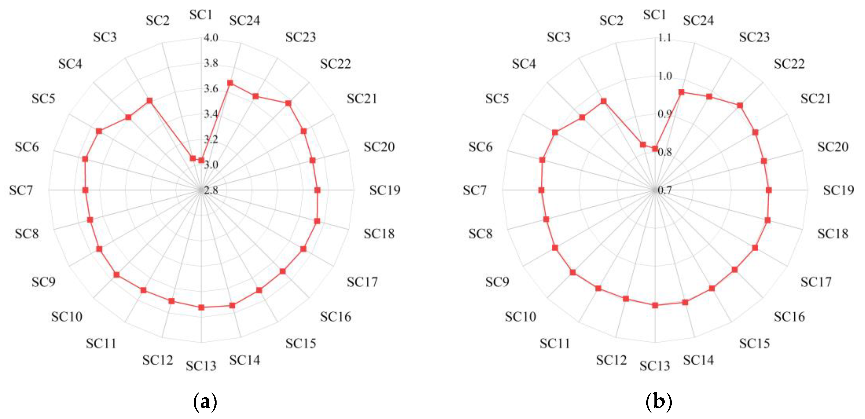
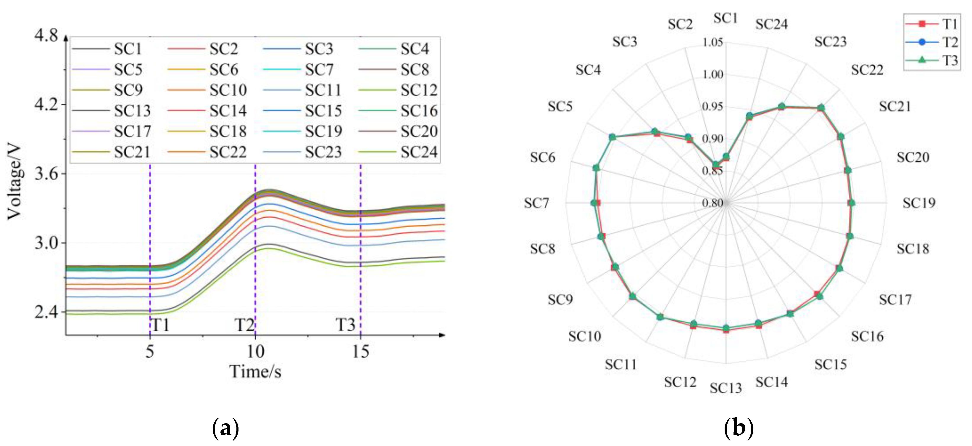
3.3.2. Normalization Process

The amplitude of the characteristic frequency of a search coil varies as the rotational speed changes, which remains consistent with the previous theoretical analysis, while the values of all the search coils can be considered equal at any moment, as shown in Figure 9a. Based on this, the voltage at the characteristic frequency of each search coil at any time is scaled to achieve robust speed. Selecting a random moment for the scalarization process, the obtained results are shown in Figure 9b.
Since the joint simulation using Maxwell-SIMPLORER requires a very small-time step-in order to observe the values at the harmonic frequencies, the simulation process requires significant computational resources and time. For this reason, the simulation results are shown here for one operating condition only.
Figure 10 shows the fault detection result for short circuit resistance of 3 ohm under its 15 turns, where it can be seen that the induced voltage of the search coil near the fault location is significantly reduced, which can be used to detect the fault.

4. Experimental Validation

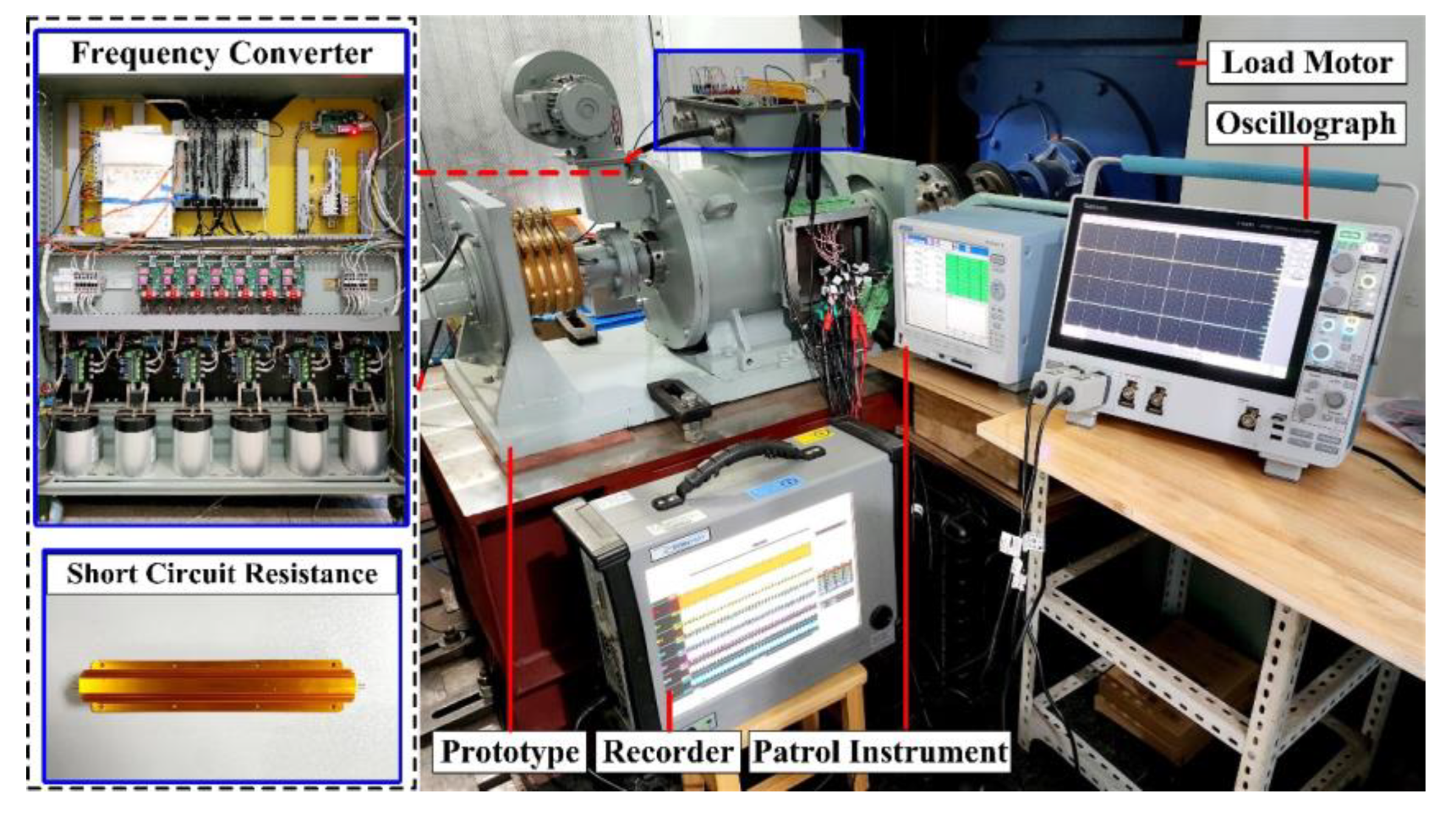
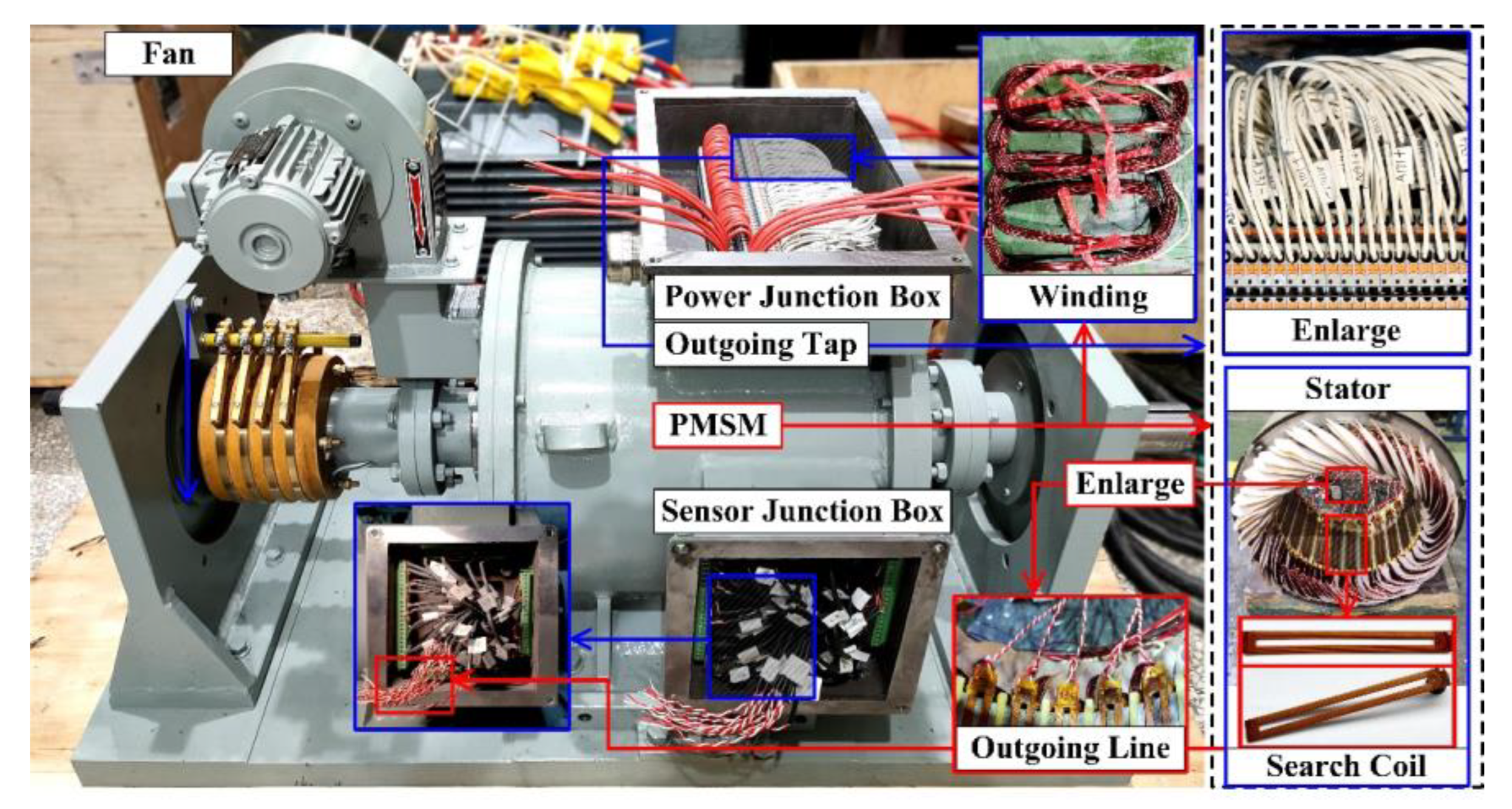
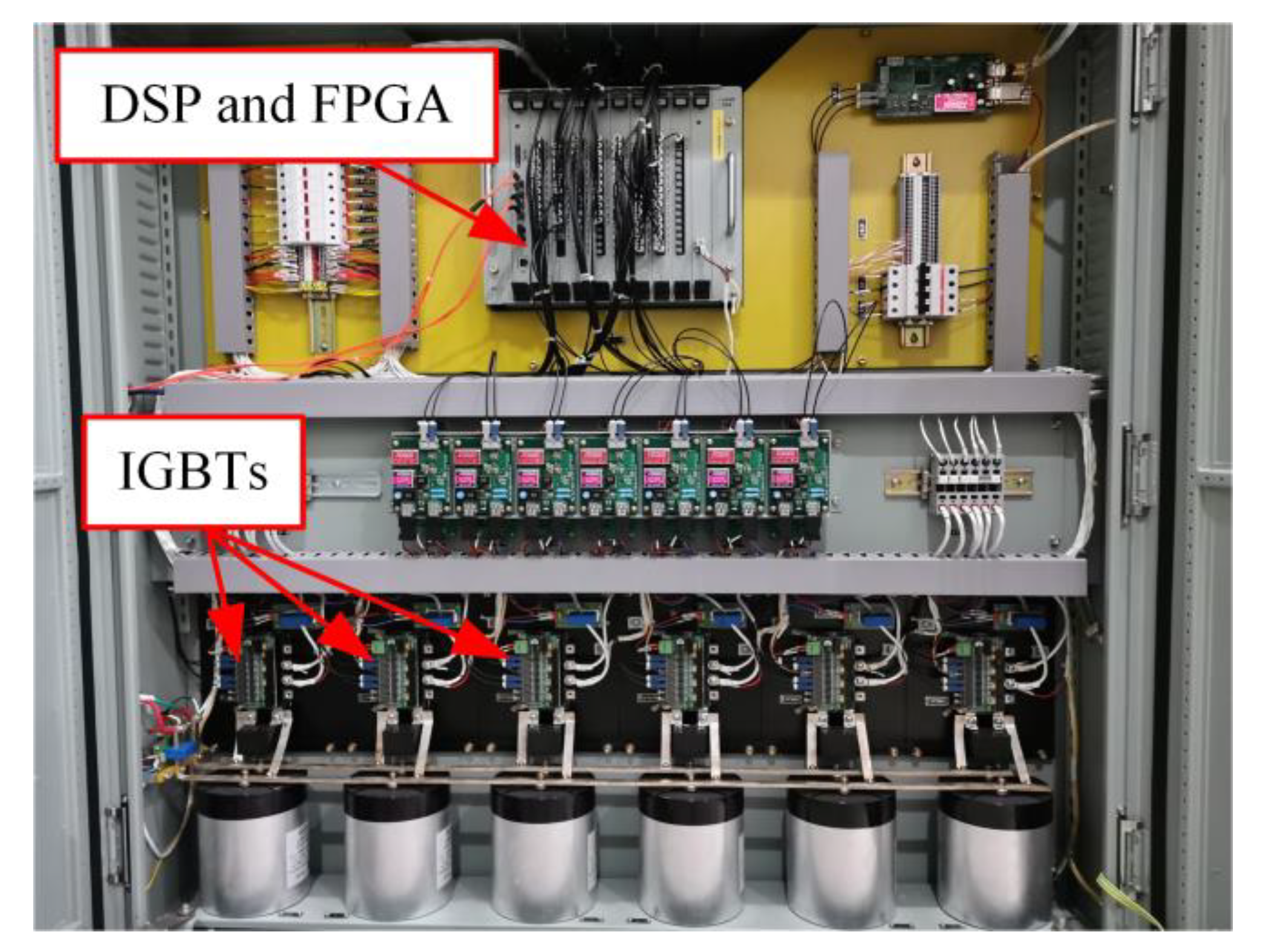
4.1. Experimental Platform

In order to verify the effectiveness of the proposed method, a laboratory-based experimental platform is built, as shown in Figure 11. The experimental platform consists of a PMSM, an induction motor as a load, and a six-phase inverter having switching frequency of 2 kHz, shown in Figure A1. The experimental data was collected using a recorder at 500 kHz sampling rate.
The ITSC fault in the experimental PMSM is generated by connecting the taps on the coils as shown in Figure 12. The taps are connected on the 7th, 15th, and 36th turn of one coil in the phase a winding. By connecting the taps with the resistors with specific resistance values, the faults of different degrees can be generated in PMSM, which would also avoid any excessive short-circuit current caused by direct shorting of the tap.
Conventional search coils are directly wound by ordinary wires. Although the process is simpler and more economical, it also has some obvious disadvantages. Especially for prototypes with a high slot filling rate, there will be not enough space for winding a sufficient number of search coils. Since the open state of the search coil is used to detect the voltage, its overcurrent capability does not need to be considered, which means that the wire diameter can be chosen arbitrarily. Flexible PCBs are chosen to make search coils due to their stability and reliability. The one-piece molding process also makes the installation process easier and faster.

4.2. Calibration

Since the search coils are installed in the slot, there will inevitably be a slot leakage problem caused by installation errors. This may result in different amplitudes at the characteristic frequencies in each search coil, even in the healthy state, as shown in Figure 13a. Therefore, it is assumed that there is a set of correction coefficients. Under the action of the correction coefficient, the output signal value of the 24 search coils is close to the fixed value in an “ideal” case. In this paper, differential evolution algorithm (DE) is used to find these correction coefficients with the minimum variance of 24 output voltages as the objective function. In this way, the detection error due to the installation factors is corrected. The corrected waveform is shown in Figure 13b.

4.3. Test Results under Failure

The resistance, number of turns, and location of short-circuit are the three most crucial factors causing inter-turn short-circuit faults. So, three types of tests are conducted to verify the effectiveness of the proposed scheme in determining these three factors.

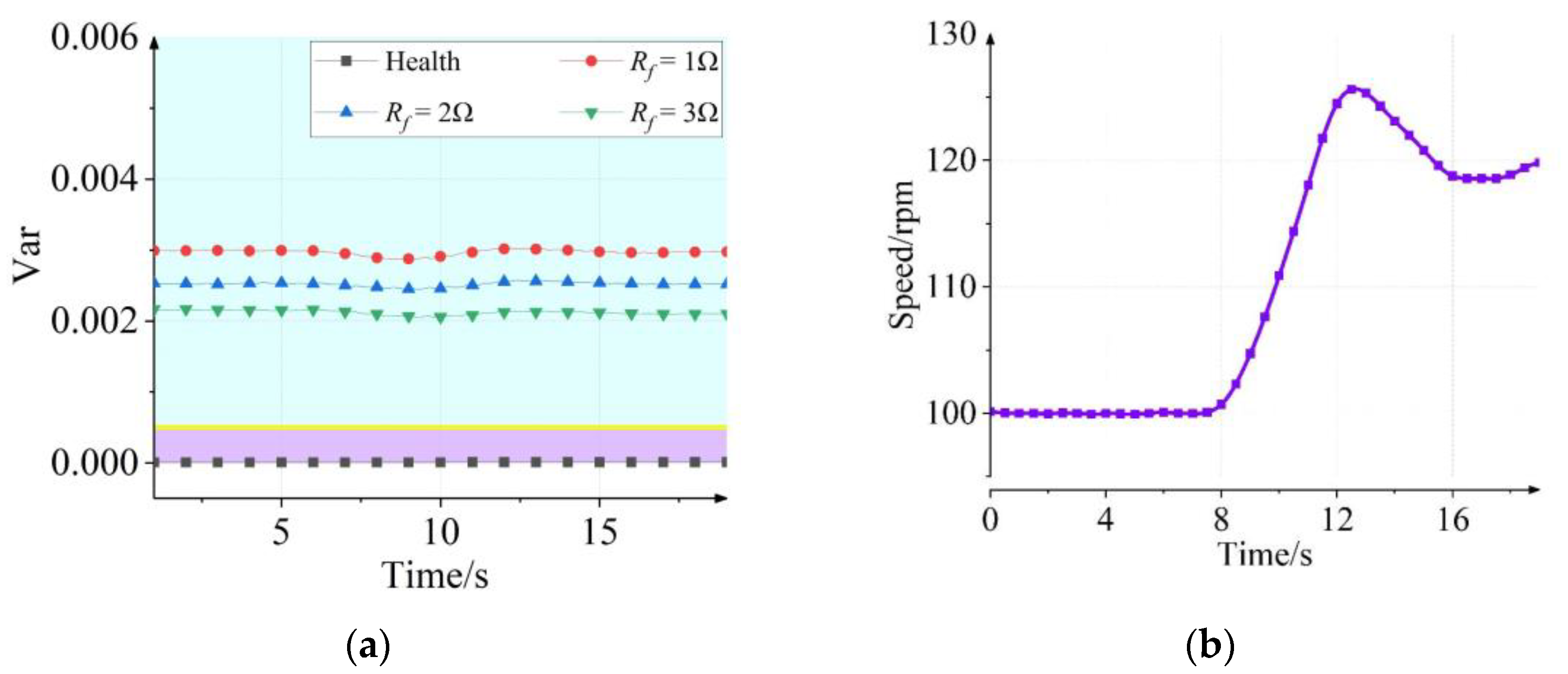
4.3.1. Change in Short Circuit Resistance

Different values to the resistance of short-circuit are set, while its number of turns and position are kept fixed. In order to avoid any damage to the motor due to any excessive heat generated by the current of the short-circuit, the resistance values to its resistors are set as 1 ohm, 2 ohm, and 3 ohm. Figure 14 represents the result of voltage in every search coil and normalized voltage value at 3 random moments where the short circuit resistance is set to 1 ohm and 15 short circuit turns.
Compared to the healthy condition, the amplitude of the voltage induced in the search coil decreases near the faulty winding, while that at other locations remains the same, as shown in Figure 14b.
The voltage induced in the search coil is not the same at different levels of the fault. Therefore, the variance of the amplitude of the voltage of the search coil after the standardization as the fault level indicator is shown in Figure 15.
It can be seen from Figure 15a that the voltage variance is almost zero at any moment in the healthy state, while it is not zero after the occurrence of a fault. Moreover, as the degree of fault increases, i.e., the resistance of the short-circuit becomes smaller, the variance of the voltage increases. Comparing Figure 15a and Figure 15b, it is seen that the variance of the voltage fluctuates slightly when the speed changes, but the magnitude of the fluctuation is small and does not affect the detected results.

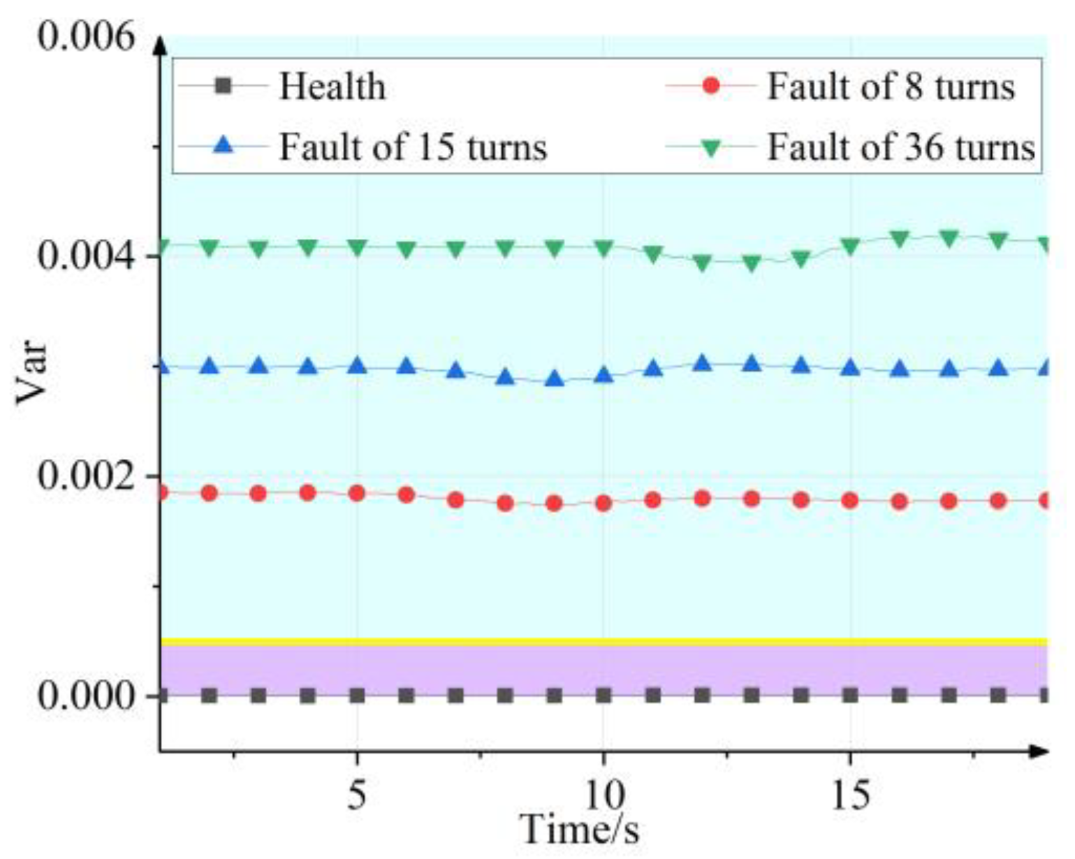
4.3.2. Change in Short Circuit Turns

The number of short-circuit turns is another crucial indicator to describe the degree of failure. The short-circuit resistance is set to 1 ohm, and the location of the fault is limited to the same slot. For these conditions, the variance values of the voltage of the search coil are shown in Figure 16 under different short-circuit turns.
It can be seen that the variance of the voltage increases as the level of fault increases, and it becomes much larger than that in the healthy state.

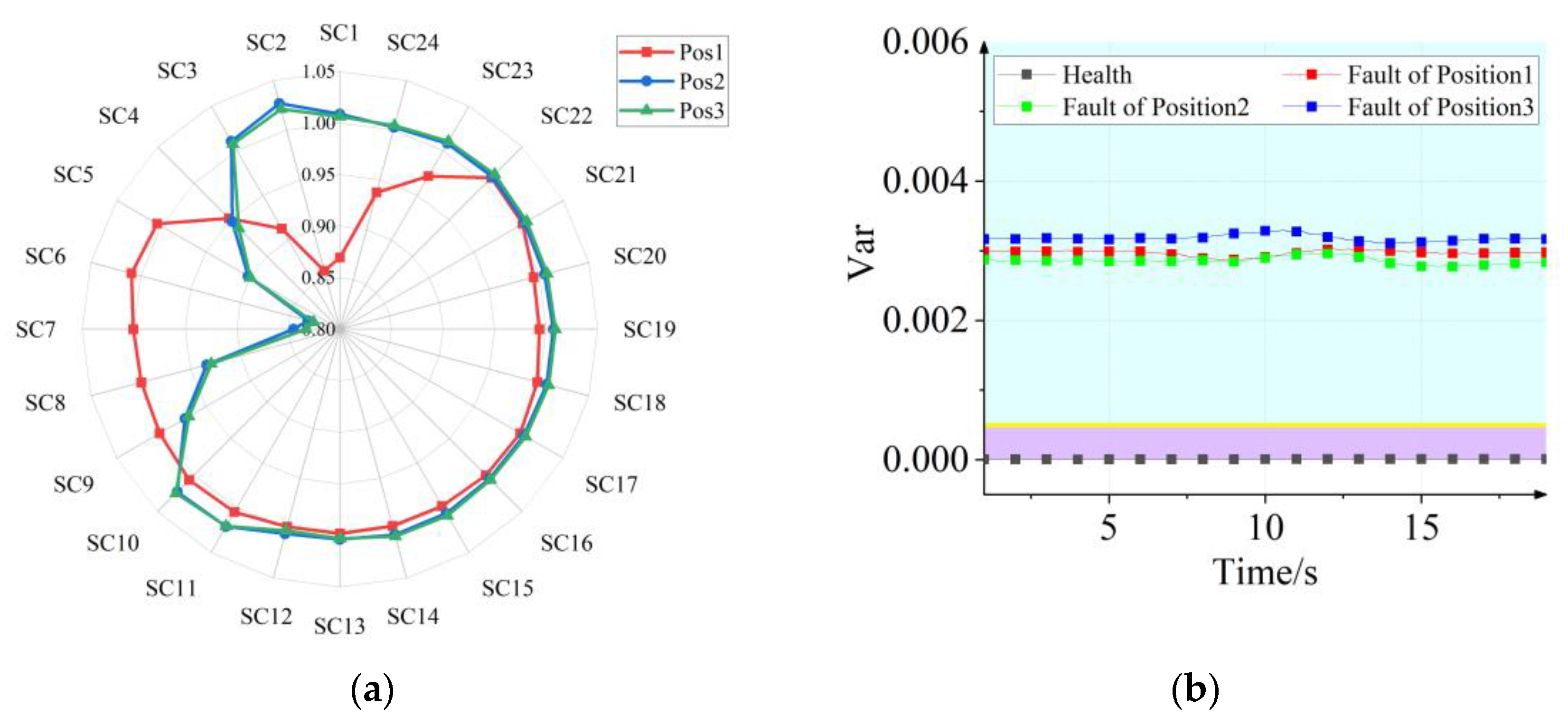
4.3.3. Change in Short Circuit Position

Since the search coils are evenly distributed on the circumference, the winding failure will directly affect the output of the search coils in its vicinity, while those of the search coils away from the fault location are not obvious. So, the location of the winding failure can be considered to provide valuable reference for maintenance.
Figure 17a shows the results of the search coils at different short circuit locations, where the red curve represents a fault occurring in phase a; the blue and green curves represent a fault occurring in phase b—but located at different locations within a single slot. Figure 17b shows the variances of the voltage for the above three cases. Obviously, there is no significant difference in the variances of the voltage at the same level of the fault.

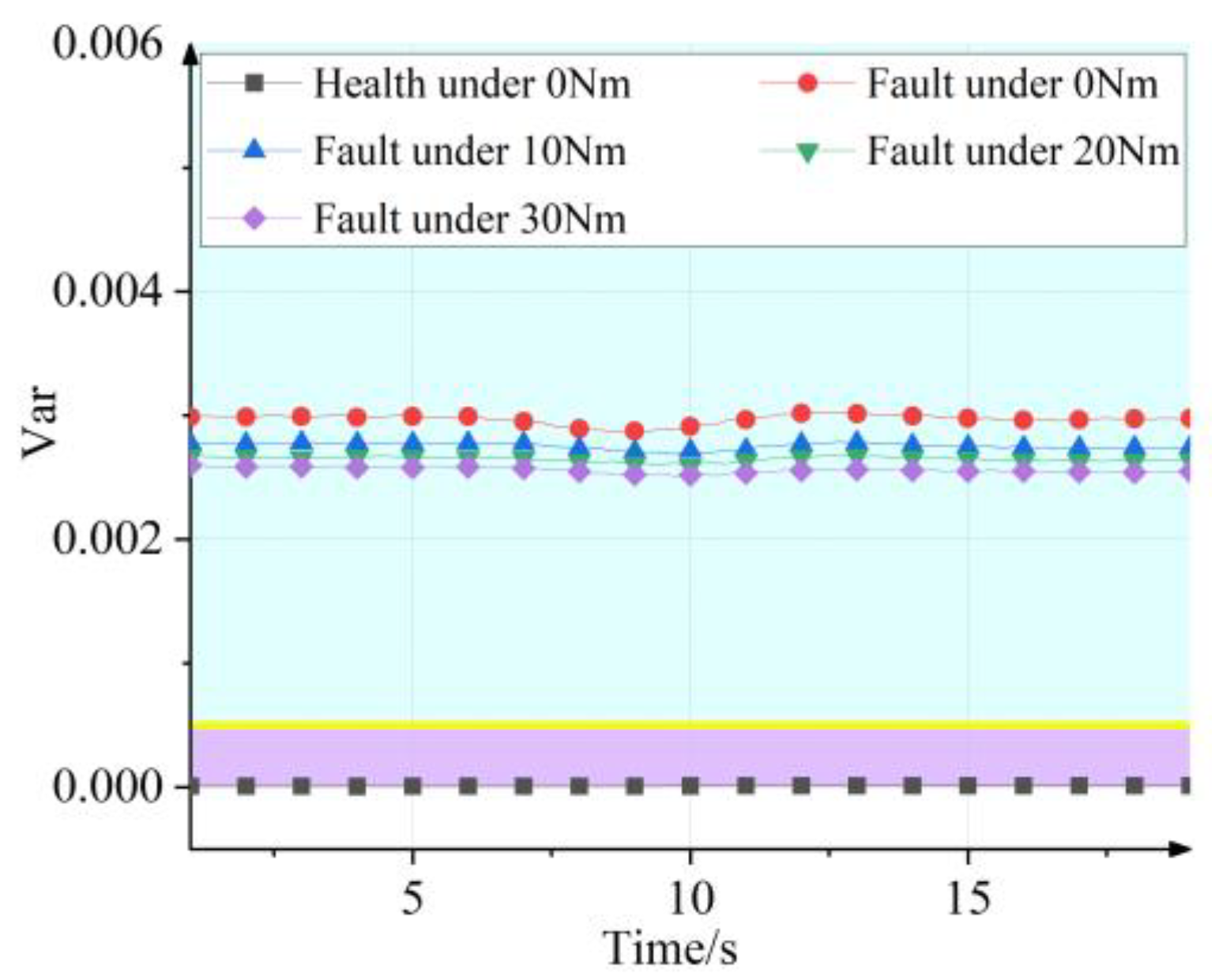
4.3.4. Change in Load

In many applications of permanent magnet motors, variations in load are inevitable. So, it is necessary to verify the effectiveness of the detection scheme under different loading conditions. Figure 18 shows the variances of voltage at different loads, while other fault conditions are kept fixed.
Obviously, the variance of voltage decreases with increasing load at the same fault level. This result can be explained by Equations (10) and (18), where the same fault level means the same mutual inductance matrix. However, an increase in load will also increase the modulation ratio, further changing the high frequency current. The voltage induced at the characteristic frequency in the search coil will increase approximately in equal proportion, while the variance will decrease.

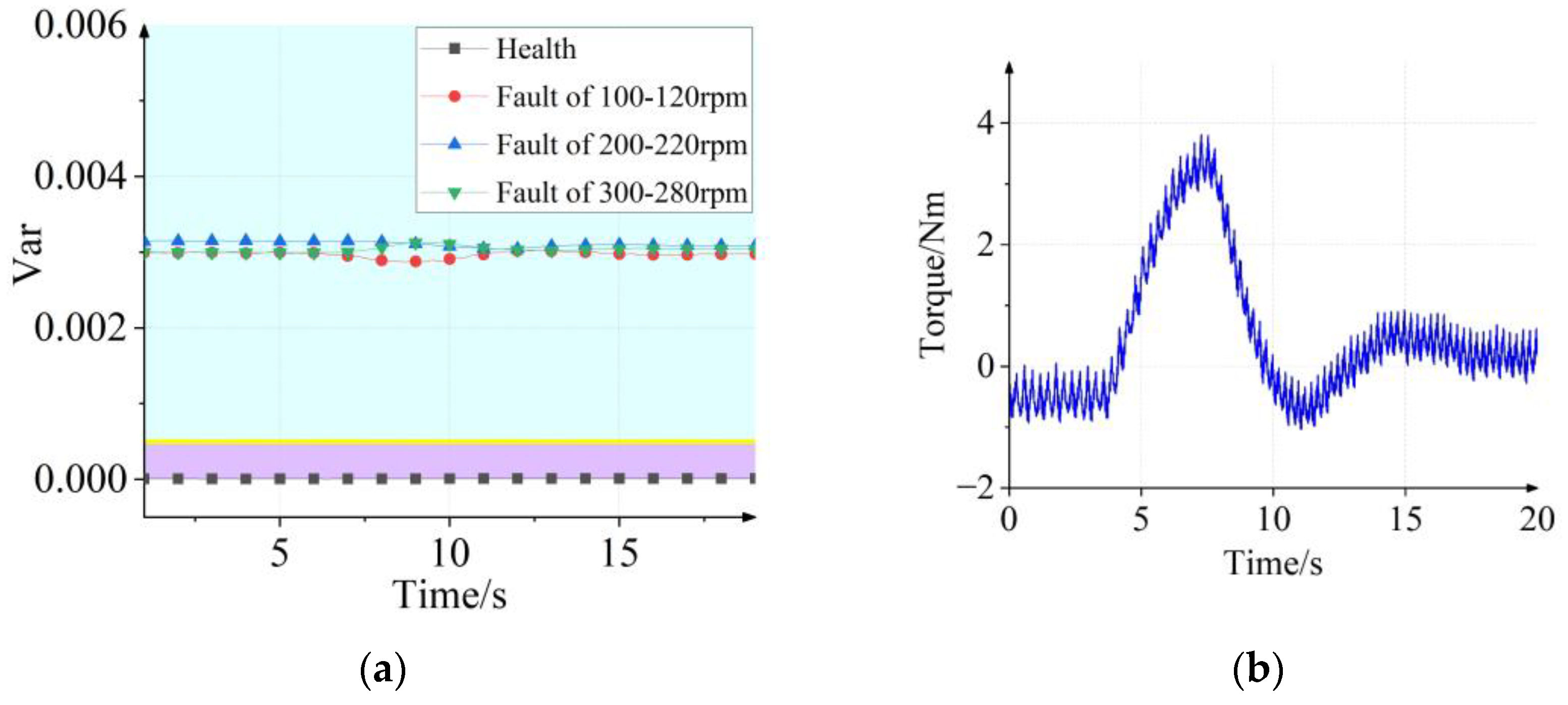
4.3.5. Change in Speed

The important advantage of the proposed method is that the fault detection results are not affected by any change in speed. Although the aforementioned experiments were conducted under variable speed, the variation in speed was made around 20 rpm due to the limited recording time. So, it was not possible to achieve results at many speed values. This subsection verifies the test results under three operating conditions, 100–120 rpm, 200–220 rpm, and 300–280 rpm, as shown in Figure 19a.
From Figure 19a, it can be seen that the detection results remain approximately constant at different speeds. The slight fluctuation in the middle of each curve is due to the torque change. Figure 19b shows the corresponding change in torque during the ramp-up of the motor from 100 rpm to 120 rpm, with a slight decrease in the variance of voltage as the torque increases.

5. Conclusions

In this article, a DLIA technique-based method for inter-turn short circuit fault diagnosis is presented, which can effectively diagnose turn-to-turn short-circuit faults in permanent magnet motors under dynamic conditions. This technology has important implications for motor fault monitoring in unsteady state operation such as electric vehicles. The variance of voltage at the characteristic frequency is chosen as the final fault indicator. This indicator value is approximately zero when the motor is in a healthy state, and it will be significantly greater than zero if a failure occurs. It is crucial that this fault detection indicator is only related to the degree of fault and has nothing to do with the running state of the motor. However, the mapping relationship between the degree of fault and eigenvalues needs to be investigated further.

Author Contributions

Conceptualization, W.H. and J.H.; methodology, W.H. and J.H.; software, W.H. and H.L.; validation, W.H. and K.L.; formal analysis, W.H.; writing—original draft preparation, W.H.; writing—review and editing, W.H., J.H. and J.C. All authors have read and agreed to the published version of the manuscript.

Funding

This research was funded by National Natural Science Foundation of China, grant number 51825703 and 52207047.

Data Availability Statement

Not applicable.

Acknowledgments

The authors would like to thank for the funding from the National Natural Science Foundation of China.

Conflicts of Interest

The authors declare no conflict of interest.

Appendix A

The detailed dimensions and materials of the motor are shown in Table A1.
Table A1. The main dimensions and materials of the six-phase surface PMSM.
ParameterValueParameterValue
Length of unilateral air gap2 mmSlot width4.2 mm
Stator outer diameter290 mmThickness of permanent magnet9 mm
Inner diameter of stator180 mmOverlaying coefficient0.97
Rotor outer diameter176 mmNumber of stator slots72
Inside diameter of rotor80 mmNumber of conductors per slot72
Stator core length88 mmNumber of parallel branches1
Yoke thickness22 mmPitch6
Stator core material50WW310Winding coefficient1
Rotor core material16MnPermanent magnet materialSmCo30

Appendix B

Based on a six-phase surface mount permanent magnet synchronous motor system, the stator winding interturn short circuit fault is studied in this paper. The inverter is shown in Figure A1. The IGBT module of Mitsubishi PM75RLA120, the current sensor of LEM Company LA 55-P/SP50, and the decoding chip of Texas Instruments company ADS1203 are selected.
Figure A1. Six-phase H-bridge inverter.
Electronics 12 02827 g0a1

References

  1. Zafarani, M.; Bostanci, E.; Qi, Y.; Goktas, T.; Akin, B. Interturn Short-Circuit Faults in Permanent Magnet Synchronous Machines: An Extended Review and Comprehensive Analysis. IEEE J. Emerg. Sel. Top. Power Electron. 2018, 6, 2173–2191. [Google Scholar] [CrossRef]
  2. Xu, Z.; Zhang, J.; Cheng, M. Investigation of Signal Injection Methods for Fault Detection of PMSM Drives. IEEE Trans. Energy Convers. 2022, 37, 2207–2216. [Google Scholar] [CrossRef]
  3. Report of Large Motor Reliability Survey of Industrial and Commercial Installations, Part I. IEEE Trans. Ind. Appl. 1985, IA-21, 853–864. [CrossRef]
  4. Cheng, S.; Habetler, T.G. Using Only the DC Current Information to Detect Stator Turn Faults in Automotive Claw-Pole Generators. IEEE Trans. Ind. Electron. 2013, 60, 3462–3471. [Google Scholar] [CrossRef]
  5. Wallmark, O.; Harnefors, L.; Carlson, O. Control algorithms for a fault-tolerant PMSM drive. IEEE Trans. Ind. Electron. 2007, 54, 1973–1980. [Google Scholar] [CrossRef]
  6. Jeong, H.; Moon, S.; Kim, S.W. An Early Stage Interturn Fault Diagnosis of PMSMs by Using Negative-Sequence Components. IEEE Trans. Ind. Electron. 2017, 64, 5701–5708. [Google Scholar] [CrossRef]
  7. Wei, D.; Liu, K.; Hu, W.; Peng, X.; Chen, Y.; Ding, R. Short-Time Adaline Based Fault Feature Extraction for Inter-Turn Short Circuit Diagnosis of PMSM via Residual Insulation Monitoring. IEEE Trans. Ind. Electron. 2023, 70, 3103–3114. [Google Scholar] [CrossRef]
  8. Song, Q.; Wang, M.; Lai, W.; Zhao, S. On Bayesian Optimization-Based Residual CNN for Estimation of Inter-Turn Short Circuit Fault in PMSM. IEEE Trans. Power Electron. 2023, 38, 2456–2468. [Google Scholar] [CrossRef]
  9. Lee, H.; Jeong, H.; Koo, G.; Ban, J.; Kim, S.W. Attention Recurrent Neural Network-Based Severity Estimation Method for Interturn Short-Circuit Fault in Permanent Magnet Synchronous Machines. IEEE Trans. Ind. Electron. 2021, 68, 3445–3453. [Google Scholar] [CrossRef]
  10. Wang, H.; Wang, J.; Wang, X.; Lu, S.; Hu, C.; Cao, W. Detection and Evaluation of the Interturn Short Circuit Fault in a BLDC-Based Hub Motor. IEEE Trans. Ind. Electron. 2023, 70, 3055–3068. [Google Scholar] [CrossRef]
  11. Ebrahimi, B.M.; Faiz, J. Feature Extraction for Short-Circuit Fault Detection in Permanent-Magnet Synchronous Motors Using Stator-Current Monitoring. IEEE Trans. Power Electron. 2010, 25, 2673–2682. [Google Scholar] [CrossRef]
  12. Park, J.; Hur, J. Detection of Inter-Turn and Dynamic Eccentricity Faults Using Stator Current Frequency Pattern in IPM-Type BLDC Motors. IEEE Trans. Ind. Electron. 2016, 63, 1771–1780. [Google Scholar] [CrossRef]
  13. Zanardelli, W.G.; Strangas, E.G.; Aviyente, S. Identification of Intermittent Electrical and Mechanical Faults in Permanent-Magnet AC Drives Based on Time–Frequency Analysis. IEEE Trans. Ind. Appl. 2007, 43, 971–980. [Google Scholar] [CrossRef]
  14. Obeid, N.H.; Battiston, A.; Boileau, T.; Nahid-Mobarakeh, B. Early Intermittent Interturn Fault Detection and Localization for a Permanent Magnet Synchronous Motor of Electrical Vehicles Using Wavelet Transform. IEEE Trans. Transp. Electrif. 2017, 3, 694–702. [Google Scholar] [CrossRef]
  15. Khan, M.; Rahman, M.A. Development and Implementation of a Novel Fault Diagnostic and Protection Technique for IPM Motor Drives. IEEE Trans. Ind. Electron. 2009, 56, 85–92. [Google Scholar] [CrossRef]
  16. Wang, C.; Liu, X.; Chen, Z. Incipient Stator Insulation Fault Detection of Permanent Magnet Synchronous Wind Generators Based on Hilbert–Huang Transformation. IEEE Trans. Magn. 2014, 50, 1–4. [Google Scholar] [CrossRef]
  17. Saavedra, H.; Urresty, J.-C.; Riba, J.-R.; Romeral, L. Detection of interturn faults in PMSMs with different winding configurations. Energy Convers. Manag. 2014, 79, 534–542. [Google Scholar] [CrossRef]
  18. Ruiz, J.R.; Rosero, J.A.; Espinosa, A.G.; Romeral, L. Detection of Demagnetization Faults in Permanent-Magnet Synchronous Motors Under Nonstationary Conditions. IEEE Trans. Magn. 2009, 45, 2961–2969. [Google Scholar] [CrossRef]
  19. Mohammed, O.A.; Liu, Z.; Liu, S. Internal Short Circuit Fault Diagnosis for PM Machines Using FE-Based Phase Variable Model and Wavelets Analysis. IEEE Trans. Magn. 2007, 43, 1729–1732. [Google Scholar] [CrossRef]
  20. Huang, N.; Shen, Z.; Long, S.R.; Wu, M.L.C.; Shih, H.H.; Zheng, Q.; Yen, N.C.; Tung, C.-C.; Liu, H.H. The empirical mode decomposition and the Hilbert spectrum for nonlinear and non-stationary time series analysis. Proc. R. Soc. Lond. Ser. A Math. Phys. Eng. Sci. 1998, 454, 903–995. [Google Scholar] [CrossRef]
  21. Hang, J.; Zhang, J.; Cheng, M.; Huang, J. Online Interturn Fault Diagnosis of Permanent Magnet Synchronous Machine Using Zero-Sequence Components. IEEE Trans. Power Electron. 2015, 30, 6731–6741. [Google Scholar] [CrossRef]
  22. Zhang, J.; Xu, Z.; Wang, J.; Zhao, J.; Din, Z.U.; Cheng, M. Detection and Discrimination of Incipient Stator Faults for Inverter-Fed Permanent Magnet Synchronous Machines. IEEE Trans. Ind. Electron. 2020, 68, 7505–7515. [Google Scholar] [CrossRef]
  23. Hu, R.; Wang, J.; Mills, A.R.; Chong, E.; Sun, Z. Current-Residual-Based Stator Interturn Fault Detection in Permanent Magnet Machines. IEEE Trans. Ind. Electron. 2021, 68, 59–69. [Google Scholar] [CrossRef]
  24. Bouzid, M.B.K.; Champenois, G. An Efficient Simplified Physical Faulty Model of a Permanent Magnet Synchronous Generator Dedicated to Stator Fault Diagnosis Part II: Automatic Stator Fault Diagnosis. IEEE Trans. Ind. Appl. 2017, 53, 2762–2771. [Google Scholar] [CrossRef]
  25. Botao, W.; Chuanwen, S.; Kexing, X.; Tingting, Z. Turn-to-turn short circuit of motor stator fault diagnosis in continuous state based on deep auto-encoder. IET Electr. Power Appl. 2019, 13, 1598–1606. [Google Scholar] [CrossRef]
  26. Zeng, C.; Huang, S.; Lei, J.; Wan, Z.; Yang, Y. Online Rotor Fault Diagnosis of Permanent Magnet Synchronous Motors Based on Stator Tooth Flux. IEEE Trans. Ind. Appl. 2021, 57, 2366–2377. [Google Scholar] [CrossRef]
  27. Da, Y.; Shi, X.; Krishnamurthy, M. A New Approach to Fault Diagnostics for Permanent Magnet Synchronous Machines Using Electromagnetic Signature Analysis. IEEE Trans. Power Electron. 2013, 28, 4104–4112. [Google Scholar] [CrossRef]
  28. Kim, K.; Lee, S.; Hur, J. Diagnosis Technique Using a Detection Coil in BLDC Motors With Interturn Faults. IEEE Trans. Magn. 2014, 50, 885–888. [Google Scholar] [CrossRef]
  29. Naderi, P. Magnetic-equivalent-circuit approach for inter-turn and demagnetisation faults analysis in surface mounted permanent-magnet synchronous machines using pole specific search-coil technique. IET Electr. Power Appl. 2018, 12, 916–928. [Google Scholar] [CrossRef]
  30. Zeng, C.; Huang, S.; Yang, Y.; Wu, D. Inter-turn fault diagnosis of permanent magnet synchronous machine based on tooth magnetic flux analysis. IET Electr. Power Appl. 2018, 12, 837–844. [Google Scholar] [CrossRef]
  31. Huang, W.; Du, B.; Li, T.; Sun, Y.; Cheng, Y.; Cui, S. Interturn Short-Circuit Fault Diagnosis of Interior Permanent Magnet Synchronous Motor for Electric Vehicle Based on Search Coil. IEEE Trans. Power Electron. 2023, 38, 2506–2515. [Google Scholar] [CrossRef]
  32. Qi, Y.; Bostanci, E.; Zafarani, M.; Akin, B. Severity Estimation of Interturn Short Circuit Fault for PMSM. IEEE Trans. Ind. Electron. 2019, 66, 7260–7269. [Google Scholar] [CrossRef]
  33. Holmes, G.; Lipo, T. Pulse Width Modulation for Power Converter; Wiley-IEEE Press: Hoboken, NJ, USA, 2006. [Google Scholar] [CrossRef]
Figure 1. The spectrum of the phase voltage.
Electronics 12 02827 g001
Figure 2. Six−phase equivalent circuit model with ITSC fault in phase a.
Electronics 12 02827 g002
Figure 3. The process of envelope amplitude calculation.
Electronics 12 02827 g003
Figure 4. Block diagram of the FEA supported system simulation.
Electronics 12 02827 g004
Figure 5. Search coil arrangement scheme.
Electronics 12 02827 g005
Figure 6. Cross section of prototype with inter-turn short fault in phase a. Shorting circuit windings are distinguished by red color. Case1 and Case2 represent two fault locations, respectively, where the fault location is closer to the bottom of the slot in Case2 compared with Case1.
Electronics 12 02827 g006
Figure 7. Signal waveform of SC1 (a) Original voltage signal. (b) Voltage signal after bandpass filtering, red and blue represent orthogonal sine and cosine signals, respectively.
Electronics 12 02827 g007
Figure 8. Test results under variable speed operation. (a) Calculated amplitude of voltage of SCs. (b) Rotational speed curve.
Electronics 12 02827 g008
Figure 9. Simulation results of the health state under variable speed operation. (a) Calculated amplitude of voltage. (b) Normalized voltage value.
Electronics 12 02827 g009
Figure 10. Simulation results of fault state under variable speed operation. (a) Calculated amplitude of voltage. (b) Normalized voltage value.
Electronics 12 02827 g010
Figure 11. The experimental platform.
Electronics 12 02827 g011
Figure 12. Details of the prototype.
Electronics 12 02827 g012
Figure 13. Amplitude of each search coil in healthy condition. (a) Before calibration. (b) After calibration.
Electronics 12 02827 g013
Figure 14. Detection result with the fault of 1 ohm and 15 short circuit turns. (a) Measured voltage value. (b) Normalized voltage value at three random moments.
Electronics 12 02827 g014
Figure 15. Detection results at different short resistance. (a) Variance of voltage. (b) Rotational speed curve.
Electronics 12 02827 g015
Figure 16. Variance of search coil output values at a different number of short-circuit turns with the short circuit resistance set to 1 ohm.
Electronics 12 02827 g016
Figure 17. Detection results at different fault positions. (a) Normalized voltage value at different fault position. (b) Variance of normalized voltage at different moments.
Electronics 12 02827 g017
Figure 18. Voltage variance under different loads with the same short circuit resistance and short circuit turns.
Electronics 12 02827 g018
Figure 19. Voltage variance at different speeds. (a) Variance of voltage. (b) Torque waveform.
Electronics 12 02827 g019
Table 1. Main parameters of PMSM.
Rated Power (kW)0.94Rated Speed (r/min)300
Rated Torque (Nm)30Stator Resistance (Ω)4.3
Number of Pole Pairs6PM Flux Linkage (Wb)0.98
Table 2. Variation of mutual inductance between phase winding and search coil (%).
abcuvwaf
SC1−0.00728−0.00823−0.0051−0.011570.00345−0.004570.1552
SC20.004980.012340.000440.007950.00723−0.009850.01348
SC3−0.03312−0.00842−0.00524−0.011520.00342−0.004640.21956
SC40.008280.0126−0.004920.007350.00778−0.01182−0.04365
SC50.00372−0.00777−0.00524−0.011850.00647−0.004610.00227
SC60.007410.0125−0.001690.007960.0078−0.011930.01668
SC70.00442−0.00801−0.00473−0.011180.00369−0.004230.00389
SC80.006530.012170.000850.00810.00721−0.010750.01682
SC90.00379−0.00812−0.00528−0.011790.00403−0.004690.00417
SC100.007180.01242−0.00260.007870.00761−0.011650.0177
SC110.00236−0.00753−0.0052−0.011720.0059−0.004580.00484
SC120.006770.0126−0.00310.007830.00752−0.010350.01801
SC130.00404−0.00802−0.00506−0.011580.00379−0.004460.00539
SC140.006950.01244−9.946 × 10−40.007730.00738−0.00980.01795
SC150.0034−0.00766−0.00522−0.011820.00531−0.00460.00548
SC160.006680.01262−0.002490.007760.00747−0.010570.01805
SC170.00309−0.00751−0.00517−0.011830.00559−0.004510.00556
SC180.007220.01264−0.001930.007880.00766−0.010480.01796
SC190.0036−0.00764−0.00489−0.011550.00517−0.004280.00565
SC200.006850.01218−0.001960.00790.00755−0.013160.01748
SC210.00408−0.008−0.00509−0.011650.00347−0.004520.005
SC220.007070.01255−0.001940.007760.00749−0.010180.01668
SC230.003−0.00796−0.00483−0.01120.00346−0.004220.00475
SC240.0070.01243−0.004480.007250.00765−0.011990.01248
Disclaimer/Publisher’s Note: The statements, opinions and data contained in all publications are solely those of the individual author(s) and contributor(s) and not of MDPI and/or the editor(s). MDPI and/or the editor(s) disclaim responsibility for any injury to people or property resulting from any ideas, methods, instructions or products referred to in the content.

